EP1435480A2 - Sanitary fitting - Google Patents
Sanitary fitting Download PDFInfo
- Publication number
- EP1435480A2 EP1435480A2 EP03029834A EP03029834A EP1435480A2 EP 1435480 A2 EP1435480 A2 EP 1435480A2 EP 03029834 A EP03029834 A EP 03029834A EP 03029834 A EP03029834 A EP 03029834A EP 1435480 A2 EP1435480 A2 EP 1435480A2
- Authority
- EP
- European Patent Office
- Prior art keywords
- valve
- adapter
- sanitary fitting
- base
- fitting according
- Prior art date
- Legal status (The legal status is an assumption and is not a legal conclusion. Google has not performed a legal analysis and makes no representation as to the accuracy of the status listed.)
- Granted
Links
Images


Classifications
-
- E—FIXED CONSTRUCTIONS
- E03—WATER SUPPLY; SEWERAGE
- E03C—DOMESTIC PLUMBING INSTALLATIONS FOR FRESH WATER OR WASTE WATER; SINKS
- E03C1/00—Domestic plumbing installations for fresh water or waste water; Sinks
- E03C1/02—Plumbing installations for fresh water
- E03C1/04—Water-basin installations specially adapted to wash-basins or baths
- E03C1/0403—Connecting the supply lines to the tap body
-
- F—MECHANICAL ENGINEERING; LIGHTING; HEATING; WEAPONS; BLASTING
- F16—ENGINEERING ELEMENTS AND UNITS; GENERAL MEASURES FOR PRODUCING AND MAINTAINING EFFECTIVE FUNCTIONING OF MACHINES OR INSTALLATIONS; THERMAL INSULATION IN GENERAL
- F16K—VALVES; TAPS; COCKS; ACTUATING-FLOATS; DEVICES FOR VENTING OR AERATING
- F16K19/00—Arrangements of valves and flow lines specially adapted for mixing fluids
- F16K19/006—Specially adapted for faucets
-
- F—MECHANICAL ENGINEERING; LIGHTING; HEATING; WEAPONS; BLASTING
- F16—ENGINEERING ELEMENTS AND UNITS; GENERAL MEASURES FOR PRODUCING AND MAINTAINING EFFECTIVE FUNCTIONING OF MACHINES OR INSTALLATIONS; THERMAL INSULATION IN GENERAL
- F16K—VALVES; TAPS; COCKS; ACTUATING-FLOATS; DEVICES FOR VENTING OR AERATING
- F16K27/00—Construction of housing; Use of materials therefor
- F16K27/04—Construction of housing; Use of materials therefor of sliding valves
- F16K27/044—Construction of housing; Use of materials therefor of sliding valves slide valves with flat obturating members
- F16K27/045—Construction of housing; Use of materials therefor of sliding valves slide valves with flat obturating members with pivotal obturating members
Definitions
- the invention relates to a sanitary fitting with a fitting housing and a mixer valve housed therein.
- Sanitary fittings of this type are usually on the top of a Basin, a sink, a vanity or the like assembled. Supply lines to the sanitary fitting lead through a through the sanitary fitting covered opening in the sink.
- an additional shut-off valve with the example of the water supply a washing machine, a dishwasher or the like can be turned on.
- the fitting often has different ones Fulfill functions.
- the shut-off valve should, for example serve to allow a diversion of cold water, or the diversion of the warm water. It is also conceivable that the shut-off valve an additional line with mixed temperature water should serve.
- the invention is based on the object, a sanitary fitting such to design that they without constructive changes during assembly can be adapted to a wide variety of applications.
- the invention proposes a sanitary fitting with the features mentioned in claim 1. Further developments of Invention are the subject of dependent claims.
- the installer can decide which of the Use cases and then the valve by simple measures adapt to this application. So he can stop With which line the derivative can be connected by the additional valve should be. This means that the leading away from the valve Line opened and closed using the additional shut-off valve can be, so for example, the cold water pipe.
- the adaptation to the application case can be done, for example happen that a part of the fitting is changed, preferably one Part that is housed within the valve body so that you can not see him from the outside. For example, then the continuing Line for a dishwasher with the hot water supply connected via the shut-off valve.
- the change of a part of the fitting can by a Umsteckcken a Adapters or the like happen, or by changing or Replace the connecting cables between the adapter and the floor.
- the fitting has an adapter part which has a through-channel for a connected to the mixer valve water supply and with This passageway connectable by the shut-off valve branch having. So it practically finds a tap of a through the Adapter part passing channel. In particular, it can be to act as a channel that supplies the water to the mixing valve. But it is also conceivable and is within the scope of the invention that it This channel is an outlet channel of the mixing valve.
- This adapter part can be used in development of the invention in particular be arranged a base part of the valve body. Before the Fitting is mounted, this lower base part is more accessible than a further up in the fitting housing existing part. Therefore relieved this arrangement is the adaptation during assembly.
- the adapter part can in particular be designed so that it at least an opening for leading to the mixing valve and / or Having lines coming from the mixing valve. These lines are simply passed through the opening without that they are intended for a tap.
- the adapter part can for example be arranged firmly in the base part be.
- the base part can advantageously also the shut-off valve available be.
- the adapter in several angularly offset positions with the base is connectable, or in other words, that an adjustment of the adapter against the base takes place.
- This has the advantage that in the base arranged shut-off valve always at the same Can stay in place so that you can see the point where the shut-off valve is arranged, select purely from ergonomic points of view can.
- the mentioned base part may be a base part, which is housed completely within the valve body. It but can also be advantageous to a separate component, which is for example designed such that the rest of the fitting housing is detachable from the base member. If the wires in the Valve housing hoses are what is in the invention can be provided, then can then the valve body of loosen and tilt the base. This is useful in some cases For example, if a relatively large fitting mounted in one place is where a window should be opened and the window at Opening would interfere with the fitting.
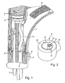
- FIG. 1 shows a broken-off view of the structure of a sanitary fitting according to the invention.
- a fitting housing 1 In a fitting housing 1 is a mixer valve 2 arranged in the form of a cartridge. Below the cartridge an adapter bottom 3 is arranged, which the liquid connections between the supply lines and the openings of the cartridge bottom manufactures. Both the mixer cartridge and the adapter base 3 should not be changed in the different use cases become.
- Part of the fitting housing 1 is a base member 4, whose position in relation to the fitting housing 1 is defined by pins 5.
- the base member 4 includes an opening 6, through the lines 7 go through it.
- the lines are in this embodiment as Hoses formed.
- the base member 4 includes a lateral projection 8, in which a valve top can be screwed for a shut-off valve.
- This shut-off valve Represents the connection between a supply line from below is inserted into the base member, and one of the base member out leading line.
- the adapter base 3 usually contains three openings, namely for a Supply line for cold water, a supply line for hot water and an outlet for mixed water.
- This outlet for mixed water is in the example connected with a hose 9, which leads to a Outlet from the valve body leads.
- the adapter part 12 can be an integral part of the base component 4, or as this opposite arranged rotatable separate Be a component. This will be explained below.
- FIG. 3 shows an embodiment modified from FIG. 1, in which the leads to the adapter base 3 as a rigid leads 15, 16 are formed. It can be seen from FIG. 3 that the connecting line 16 between the opening 13 of the adapter member 12 and the adapter bottom 3 is a rigid tube at a certain point the adapter base 3 is mounted. If the upper opening 13 of the Adapter member 12 is connected to a different location of the adapter base 3 be, the adapter member 12 must be in a different position be brought, so a position around the longitudinal axis of the leads is angularly twisted.
- Figure 5 now shows the position when the consumer on the leading away Line 22 should be supplied with hot water.
- the base component 4 is rotated together with the adapter member 12 in a position where the outlet opening 13 of the passage channel at the location is arranged, where at the bottom of the adapter base 3 the Entrance opening for hot water is.
- the line piece 20, the at the position of Figure 4 still with the inlet opening for cold water is now connected with the inlet opening for hot water connected.
- leads 21 for cold water through the Opening 6 through.
- FIG. 6 shows a position in which the sanitary fitting with a so-called non-pressurized water heater 30 should be used.
- the supply line for cold water is via the passageway of the adapter component 12 with the mixed water outlet of the adapter bottom 3 which now forms the input for the mixer cartridge.
- the Water then flows out of the mixer cartridge through two outlets from, namely the outlet for cold water 31, through the opening into the inlet of the water heater 30 leads.
- the second outlet 32 from the mixer valve leads to a tee 33, at the Output a hose 34 connected for example a shower is.
- the invention proposed by sanitary fitting with the adapter in Socket is so suitable, these three different applications without changing the structure of the valve got to.
- the adaptation is done by simply repositioning the socket component 4 with respect to the valve body. 1
- Figures 7 to 13 show in greater detail the possible structure a base component 4. While in the illustration of Figures 4 to 6 it was assumed that the adapter component 12 with the base component 4 is connected that a displacement of the adapter component 12 is possible only together with the base member 4, is in the following Embodiment, the adapter member 42 a separate component, which can be inserted into the base component 4. This one sees schematically from the figure 7.
- the base member 4 includes a multiple stepped passage 41 into which the adapter member 42 is inserted can be.
- the composite state is shown in FIG. 8, which corresponds to the figure 2.
- FIG. 9 shows a perspective view of the adapter component 42 of FIG Figures 7 and 8 from below. From the comparison of Figures 7 and 9 results itself at the top of adapter member 42, which is the mixer valve is assigned, a single opening 13 opens, while at the bottom two openings open. One of these two openings 43 is intended for the line 22 leading away from the mixing fitting, while the other opening is the lower end of the passageway forms.
- FIG. 10 shows a section through the arrangement of FIG the approach 8 is the shut-off valve 44 forming valve upper part used. Its structure is not described in detail, since it is known is.
- FIG. 11 shows the structure of the base component and of the adapter component 42 in greater detail.
- the cut is laid through the central axis.
- the passage 47 is formed by two holes meeting each other. From the passage 47 a branch 50 leads into the upper of the two circumferential grooves 45. From the groove 45 leads to a the sectional plane of Figure 11 lying channel into the receptacle 48 for the valve head.
- the channel 49 can be seen in Figure 12, as well as the Branch 50.
- the shut-off valve can be the connection between the channel 49 and the Close branch 51 in receptacle 48 and open. Thereby can the flowing through the passage 47 water flowing into the Opening 43 for the lead-out line 22 pass.
- the arrangement of the adapter member 42 as compared to the base member rotatable part has the advantage that the shut-off valve 44 receiving Approach 8 always at the same position of the valve body can be arranged.
Landscapes
- Engineering & Computer Science (AREA)
- General Engineering & Computer Science (AREA)
- Mechanical Engineering (AREA)
- Health & Medical Sciences (AREA)
- Life Sciences & Earth Sciences (AREA)
- Hydrology & Water Resources (AREA)
- Public Health (AREA)
- Water Supply & Treatment (AREA)
- Multiple-Way Valves (AREA)
- Valve Housings (AREA)
- Domestic Plumbing Installations (AREA)
Abstract
Description
Die Erfindung geht aus von einer Sanitärarmatur mit einem Armaturengehäuse und einem darin untergebrachten Mischerventil.The invention relates to a sanitary fitting with a fitting housing and a mixer valve housed therein.
Sanitärarmaturen dieser Art werden üblicherweise auf der Oberseite eines Waschbeckens, eines Spülbeckens, eines Waschtischs oder dergleichen montiert. Zuleitungen zu der Sanitärarmatur führen durch eine durch die Sanitärarmatur abgedeckte Öffnung in dem Waschbecken. Zum Anschalten von Zusatzgeräten haben solche Sanitärarmaturen häufig ein zusätzliches Absperrventil, mit dem beispielsweise die Wasserversorgung einer Waschmaschine, einer Spülmaschine oder dergleichen eingeschaltet werden kann. Dabei muss die Armatur häufig unterschiedliche Funktionen erfüllen. Das Absperrventil soll beispielsweise dazu dienen, eine Abzweigung eines kalten Wassers zu ermöglichen, oder auch die Abzweigung des warmen Wassers. Denkbar ist auch, dass das Absperrventil eine zusätzliche Leitung mit Mischtemperaturwasser bedienen soll.Sanitary fittings of this type are usually on the top of a Basin, a sink, a vanity or the like assembled. Supply lines to the sanitary fitting lead through a through the sanitary fitting covered opening in the sink. To turn on additional devices have such sanitary fittings often an additional shut-off valve, with the example of the water supply a washing machine, a dishwasher or the like can be turned on. The fitting often has different ones Fulfill functions. The shut-off valve should, for example serve to allow a diversion of cold water, or the diversion of the warm water. It is also conceivable that the shut-off valve an additional line with mixed temperature water should serve.
Es ist bereits eine Einlocheinhebelmischbatterie bekannt, die zwei Zuleitungen und eine Ableitung aufweist. Mit Hilfe eines zusätzlichen Ventils kann die Ableitung mit einer der beiden Zuleitungen verbunden werden (DE 3243750).It is already known a Einlocheinhebelmischbatterie, the two leads and having a derivative. With the help of an additional valve the derivative can be connected to one of the two supply lines (DE 3243750).
Der Erfindung liegt die Aufgabe zu Grunde, eine Sanitärarmatur derart auszugestalten, dass sie ohne konstruktive Änderungen bei der Montage an die unterschiedlichsten Anwendungsfälle angepasst werden kann.The invention is based on the object, a sanitary fitting such to design that they without constructive changes during assembly can be adapted to a wide variety of applications.
Zur Lösung dieser Aufgabe schlägt die Erfindung eine Sanitärarmatur
mit den im Anspruch 1 genannten Merkmalen vor. Weiterbildungen der
Erfindung sind Gegenstand von Unteransprüchen.To solve this problem, the invention proposes a sanitary fitting
with the features mentioned in
Bei der Montage kann der Installateur also entscheiden, welcher der Anwendungsfälle vorliegt und die Armatur dann durch einfache Maßnahmen an diesen Anwendungsfall anpassen. Er kann also einstellen, mit welcher Leitung die Ableitung durch das zusätzliche Ventil verbindbar sein soll. Dies bedeutet also, dass die von der Armatur weg führende Leitung mit Hilfe des zusätzlichen Absperrventils geöffnet und geschlossen werden kann, also beispielsweise die Kaltwasserleitung. Eine Änderung der Position des Mischventils, das beispielsweise als eine Mischerkartusche ausgebildet ist, innerhalb des Armaturengehäuses ist dann nicht mehr erforderlich.During installation, the installer can decide which of the Use cases and then the valve by simple measures adapt to this application. So he can stop With which line the derivative can be connected by the additional valve should be. This means that the leading away from the valve Line opened and closed using the additional shut-off valve can be, so for example, the cold water pipe. A Change the position of the mixing valve, for example, as a mixer cartridge is formed, is within the valve body then no longer necessary.
Die Anpassung an den Anwendungsfall kann beispielsweise dadurch geschehen, dass ein Teil der Armatur geändert wird, vorzugsweise ein Teil, der innerhalb des Armaturengehäuses so untergebracht ist, dass man ihn von außen nicht sehen kann. Beispielsweise wird also die weiterführende Leitung für eine Spülmaschine mit der Heißwasserzuleitung über das Absperrventil verbunden.The adaptation to the application case can be done, for example happen that a part of the fitting is changed, preferably one Part that is housed within the valve body so that you can not see him from the outside. For example, then the continuing Line for a dishwasher with the hot water supply connected via the shut-off valve.
Das Umändern eines Teils der Armatur kann durch ein Umstecken eines Adapters oder dergleichen geschehen, oder auch durch Umstecken oder Austauschen der Anschlussleitungen zwischen dem Adapter und dem Boden.The change of a part of the fitting can by a Umsteckcken a Adapters or the like happen, or by changing or Replace the connecting cables between the adapter and the floor.
Insbesondere kann in Weiterbildung der Erfindung vorgesehen sein, dass die Armatur ein Adapterteil aufweist, das einen Durchgangskanal für eine mit dem Mischerventil verbundene Wasserführung und eine mit diesem Durchgangskanal durch das Absperrventil verbindbare Abzweigung aufweist. Es findet also praktisch eine Anzapfung eines durch das Adapterteil hindurch führenden Kanals statt. Insbesondere kann es sich dabei um einen Kanal handeln, der das Wasser dem Mischventil zuführt. Es ist aber auch denkbar und liegt im Rahmen der Erfindung, dass es sich bei diesem Kanal um einen Ausgangskanal des Mischventils handelt.In particular, it can be provided in development of the invention, in that the fitting has an adapter part which has a through-channel for a connected to the mixer valve water supply and with This passageway connectable by the shut-off valve branch having. So it practically finds a tap of a through the Adapter part passing channel. In particular, it can be to act as a channel that supplies the water to the mixing valve. But it is also conceivable and is within the scope of the invention that it This channel is an outlet channel of the mixing valve.
Dieses Adapterteil kann in Weiterbildung der Erfindung insbesondere in einem Sockelteil des Armaturengehäuses angeordnet sein. Bevor die Armatur montiert wird, ist dieser untere Sockelteil leichter zugänglich als ein weiter oben in dem Armaturengehäuse vorhandenes Teil. Daher erleichtert diese Anordnung die Anpassung bei der Montage.This adapter part can be used in development of the invention in particular be arranged a base part of the valve body. Before the Fitting is mounted, this lower base part is more accessible than a further up in the fitting housing existing part. Therefore relieved this arrangement is the adaptation during assembly.
Dass Adapterteil kann insbesondere so ausgebildet sein, dass es mindestens eine Durchbrechung für zu dem Mischventil führende und/oder von dem Mischventil kommende Leitungen aufweist. Diese Leitungen werden einfach durch die Durchbrechung hindurchgeführt, ohne dass sie für eine Anzapfung vorgesehen sind. The adapter part can in particular be designed so that it at least an opening for leading to the mixing valve and / or Having lines coming from the mixing valve. These lines are simply passed through the opening without that they are intended for a tap.
Das Adapterteil kann beispielsweise fest in dem Sockelteil angeordnet sein. In dem Sockelteil kann mit Vorteil auch das Absperrventil vorhanden sein. Zur Anpassung an die unterschiedlichen Anwendungsfälle, bei denen ja das eigentliche Mischventil unverändert in dem Armaturengehäuse sein soll, kann dann der Sockelteil zusammen mit dem Adapterteil in seiner Position verändert werden.The adapter part can for example be arranged firmly in the base part be. In the base part can advantageously also the shut-off valve available be. To adapt to the different applications, in which yes, the actual mixing valve unchanged in the valve body should be, then the base part together with the adapter part be changed in his position.
Es ist aber ebenfalls möglich und wird von der Erfindung vorgeschlagen, dass der Adapter in mehreren winkelmäßig versetzten Positionen mit dem Sockel verbindbar ist, oder anders ausgedrückt, dass eine Verstellung des Adapters gegenüber dem Sockel erfolgt. Dies hat den Vorteil, dass das in dem Sockel angeordnete Absperrventil immer an der gleichen Stelle bleiben kann, so dass man die Stelle, an der das Absperrventil angeordnet ist, rein nach ergonomischen Gesichtspunkten auswählen kann.However, it is also possible and is proposed by the invention, that the adapter in several angularly offset positions with the base is connectable, or in other words, that an adjustment of the adapter against the base takes place. This has the advantage that in the base arranged shut-off valve always at the same Can stay in place so that you can see the point where the shut-off valve is arranged, select purely from ergonomic points of view can.
Bei dem erwähnten Sockelteil kann es sich um ein Sockelteil handeln, das vollständig innerhalb des Armaturengehäuses untergebracht ist. Es kann sich aber auch mit Vorteil um einen getrennten Bauteil handeln, das beispielsweise derart ausgebildet ist, dass der Rest des Armaturengehäuses von dem Sockelbauteil lösbar ist. Wenn die Leitungen in dem Armaturengehäuse Schläuche sind, was in Weiterbildung der Erfindung vorgesehen sein kann, so lässt sich dann das Armaturengehäuse von dem Sockelteil lösen und umlegen. Dies ist in manchen Fällen sinnvoll, wenn beispielsweise eine relativ große Armatur an einer Stelle angebracht wird, wo ein Fenster geöffnet werden soll und das Fenster beim Öffnen mit der Armatur kollidieren würde.The mentioned base part may be a base part, which is housed completely within the valve body. It but can also be advantageous to a separate component, which is for example designed such that the rest of the fitting housing is detachable from the base member. If the wires in the Valve housing hoses are what is in the invention can be provided, then can then the valve body of loosen and tilt the base. This is useful in some cases For example, if a relatively large fitting mounted in one place is where a window should be opened and the window at Opening would interfere with the fitting.
Weitere Merkmale, Einzelheiten und Vorzüge der Erfindung ergeben sich aus den Patentansprüchen und der Zusammenfassung, deren beider Wortlaut durch Bezugnahme zum Inhalt der Beschreibung gemacht wird, der folgenden Beschreibung bevorzugter Ausführungsformen der Erfindung sowie anhand der Zeichnung. Hierbei zeigen:
Figur 1- eine teilweise geschnittene abgebrochene Darstellung einer Sanitärarmatur mit einem Sockelbauteil;
Figur 2- eine Darstellung des Sockelbauteils allein;
Figur 3- eine der
Figur 1 entsprechende Darstellung einer zweiten Ausführungsform; Figur 4- die Kombination aus Sockelbauteil und Mischerkartuschenboden in einer ersten Position;
- Figur 5
- eine Kombination aus Sockelbauteil und Mischerkartuschenboden in einer zweiten Position;
Figur 6- eine der
Figur 4 und 5 entsprechende Darstellung in einer dritten Position; Figur 7- ein Sockelbauteil, das aus mehreren Teilen besteht;
Figur 8- das Sockelbauteil der
Figur 7 in zusammengesetztem Zustand; Figur 9- die Ansicht eines Adapterteils des Sockelbauteils der
Figur 8 schräg von unten; Figur 10- einen Schnitt durch das Sockelbauteil der
Figur 8; Figur 11- einen Schnitt durch das Sockelbauteil mit abgenommenem Absperrventil;
Figur 12- einen Schnitt durch das Sockelbauteil der
Figur 11 längs Linie XII - XII; Figur 13- einen Schnitt durch das Sockelbauteil der
Figur 11 längs Linie XIII - XIII.
- FIG. 1
- a partially sectioned broken view of a sanitary fitting with a base member;
- FIG. 2
- an illustration of the base member alone;
- FIG. 3
- a representation corresponding to Figure 1 of a second embodiment;
- FIG. 4
- the combination of base component and mixer cartridge bottom in a first position;
- FIG. 5
- a combination of base member and mixer cartridge bottom in a second position;
- FIG. 6
- an illustration corresponding to Figure 4 and 5 in a third position;
- FIG. 7
- a socket component consisting of several parts;
- FIG. 8
- the socket component of Figure 7 in the assembled state;
- FIG. 9
- the view of an adapter part of the base member of Figure 8 obliquely from below;
- FIG. 10
- a section through the base member of Figure 8;
- FIG. 11
- a section through the base member with the shut-off valve removed;
- FIG. 12
- a section through the base member of Figure 11 taken along line XII - XII;
- FIG. 13
- a section through the base member of Figure 11 along line XIII - XIII.
Figur 1 zeigt in einer abgebrochenen Darstellung den Aufbau einer Sanitärarmatur
nach der Erfindung. In einem Armaturengehäuse 1 ist ein Mischerventil
2 in Form einer Kartusche angeordnet. Unterhalb der Kartusche
ist ein Adapterboden 3 angeordnet, der die Flüssigkeitsverbindungen
zwischen den Zuleitungen und den Öffnungen des Kartuschenbodens
herstellt. Sowohl die Mischerkartusche als auch der Adapterboden
3 sollen bei den unterschiedlichen Anwendungsfällen nicht geändert
werden.FIG. 1 shows a broken-off view of the structure of a sanitary fitting
according to the invention. In a
Teil des Armaturengehäuses 1 ist ein Sockelbauteil 4, dessen Position
in Relation zu dem Armaturengehäuse 1 durch Stifte 5 definiert wird.
Das Sockelbauteil 4 enthält eine Durchbrechung 6, durch die Leitungen
7 hindurch gehen. Die Leitungen sind bei dieser Ausführungsform als
Schläuche ausgebildet.Part of the
Das Sockelbauteil 4 enthält einen seitlichen Ansatz 8, in den ein Ventiloberteil
für ein Absperrventil eingeschraubt werden kann. Dieses Absperrventil
stellt die Verbindung zwischen einer Zuleitung, die von unten
her in das Sockelbauteil eingeführt ist, und einer aus dem Sockelbauteil
heraus führenden Leitung her.The
Der Adapterboden 3 enthält im Regelfall drei Öffnungen, nämlich für eine
Zuleitung für kaltes Wasser, eine Zuleitung für warmes Wasser und
einen Auslass für Mischwasser. Dieser Auslass für Mischwasser ist im
dargestellten Beispiel mit einem Schlauch 9 verbunden, der zu einem
Auslauf aus dem Armaturengehäuse führt. The
Figur 2 zeigt eine perspektivische Ansicht des Sockelbauteils 4 der Figur
Das Adapterteil 12 kann einstückiger Teil des Sockelbauteils 4 sein,
oder aber als diesem gegenüber verdrehbar angeordnetes getrenntes
Bauteil sein. Dies wird im Folgenden noch erklärt werden.The
Figur 3 zeigt eine gegenüber der Figur 1 geänderte Ausführungsform,
bei der die Zuleitungen zu dem Adapterboden 3 als starre Zuleitungen
15, 16 ausgebildet sind. Es ergibt sich aus der Figur 3, dass die Verbindungsleitung
16 zwischen der Öffnung 13 des Adapterbauteils 12 und
dem Adapterboden 3 ein starres Rohr ist, das an einer bestimmten Stelle
des Adapterbodens 3 angebracht ist. Soll die obere Öffnung 13 des
Adapterbauteils 12 an einer anderen Stelle des Adapterbodens 3 angeschlossen
werden, muss das Adapterbauteil 12 in eine andere Position
gebracht werden, also eine Position, die um die Längsachse der Zuleitungen
winkelmäßig verdreht ist.FIG. 3 shows an embodiment modified from FIG. 1,
in which the leads to the
Beispiele für diese unterschiedliche Verbindung ergeben sich aus den
Figuren 4 bis 6. In Figur 4 ist die obere Öffnung 13 des Durchgangskanals
des Adapterbauteils mit Hilfe eines Leitungsstücks 20 mit dem
Kaltwassereingang des Adapterbodens 3 verbunden. Mit dem in Figur 4
nicht sichtbaren unteren Ende des Durchgangskanals des Adapterbauteils
12 ist demzufolge die Kaltwasserzuleitung 21 verbunden. Das in
den Ansatz 8 einzusetzende Ventiloberteil stellt die Verbindung zwischen
der Kaltwasserzuleitung 21 und der wegführenden Leitung 22 her.
Die Zuleitung 23 für warmes Wasser und die Ableitung 24 für Mischwasser
führen durch die Durchbrechung 6 des Adapterbauteils 12 hindurch.
Dieser Anwendungsfall gilt für den Fall, dass der mit Hilfe des Absperrventils
zu bedienende Verbraucher mit kaltem Wasser versorgt werden
soll.Examples of this different connection will be apparent from the
Figures 4 to 6. In Figure 4, the
Figur 5 zeigt nun die Position, wenn der Verbraucher über die wegführende
Leitung 22 mit heißem Wasser versorgt werden soll. Das Sockelbauteil
4 ist zusammen mit dem Adapterbauteil 12 in eine Position verdreht
worden, wo die Ausgangsöffnung 13 des Durchgangskanals an
der Stelle angeordnet ist, wo an der Unterseite des Adapterbodens 3 die
Eingangsöffnung für heißes Wasser ist. Das Leitungsstück 20, das bei
der Position der Figur 4 noch mit der Einlassöffnung für kaltes Wasser
verbunden war, ist jetzt also mit der Einlassöffnung für heißes Wasser
verbunden. Dagegen führt die Zuleitung 21 für kaltes Wasser durch die
Durchbrechung 6 hindurch.Figure 5 now shows the position when the consumer on the leading away
Figur 6 zeigt eine Position, bei der die Sanitärarmatur mit einem so genannten
drucklosen Durchlauferhitzer 30 verwendet werden soll. Hier
wird die Zuleitung für kaltes Wasser über den Durchgangskanal des Adapterbauteils
12 mit dem Mischwasserausgang des Adapterbodens 3
verbunden, der jetzt den Eingang für die Mischerkartusche bildet. Das
Wasser strömt dann aus der Mischerkartusche durch zwei Auslässe
aus, nämlich den Auslass für kaltes Wasser 31, der durch die Durchbrechung
in den Einlass des Durchlauferhitzers 30 führt. Der zweite Auslass
32 aus dem Mischerventil führt zu einem T-Stück 33, an dessen
Ausgang ein Schlauch 34 für beispielsweise eine Brause angeschlossen
ist. Figure 6 shows a position in which the sanitary fitting with a so-called
Die von Erfindung vorgeschlagene Sanitärarmatur mit dem Adapter im
Sockel ist also geeignet, diese drei unterschiedlichen Anwendungsfälle
abzudecken, ohne dass die Armatur in ihrem Aufbau geändert werden
muss. Die Anpassung geschieht durch einfaches Umstecken des Sockelbauteils
4 gegenüber dem Armaturengehäuse 1.The invention proposed by sanitary fitting with the adapter in
Socket is so suitable, these three different applications
without changing the structure of the valve
got to. The adaptation is done by simply repositioning the
Die Figuren 7 bis 13 zeigen in größerer Einzelheit den möglichen Aufbau
eines Sockelbauteils 4. Während bei der Darstellung der Figuren 4 bis 6
davon ausgegangen wurde, dass das Adapterbauteil 12 so mit dem Sockelbauteil
4 verbunden ist, dass eine Versetzung des Adapterbauteils
12 nur zusammen mit dem Sockelbauteil 4 möglich ist, ist bei der folgenden
Ausführungsform das Adapterbauteil 42 ein getrenntes Bauteil,
das in das Sockelbauteil 4 eingesetzt werden kann. Dies sieht man
schematisch aus der Figur 7. Das Sockelbauteil 4 enthält einen mehrfach
abgestuften Durchgang 41, in den das Adapterbauteil 42 eingesetzt
werden kann. Der zusammengesetzte Zustand ist in Figur 8 dargestellt,
die der Figur 2 entspricht.Figures 7 to 13 show in greater detail the possible structure
a
Figur 9 zeigt eine perspektivische Ansicht des Adapterbauteils 42 der
Figur 7 und 8 von unten. Aus dem Vergleich der Figuren 7 und 9 ergibt
sich, dass an der Oberseite des Adapterbauteils 42, die dem Mischerventil
zugeordnet ist, eine einzige Öffnung 13 ausmündet, während an
der Unterseite zwei Öffnungen ausmünden. Eine dieser beiden Öffnungen
43 ist für die von der Mischarmatur weg führende Leitung 22 gedacht,
während die andere Öffnung das untere Ende des Durchgangskanals
bildet.FIG. 9 shows a perspective view of the
Figur 10 zeigt nun einen Schnitt durch die Anordnung der Figur 8. In
dem Ansatz 8 ist das das Absperrventil 44 bildende Ventiloberteil eingesetzt.
Sein Aufbau wird nicht näher beschrieben, da er an sich bekannt
ist. FIG. 10 shows a section through the arrangement of FIG
the
In der Außenseite des Adapterbauteils 42 sind zwei umlaufende Nuten
45, 46 gebildet. Die Verbindung zwischen den beiden Nuten 45, 46 kann
über das Sockelbauteil 4 geschehen, was im Folgenden noch zu sehen
ist. Die Verbindung wird durch das Absperrventil 44 geöffnet und geschlossen.
Aus dem Durchgangskanal führt eine Abzweigung in die eine
Nut 45, während der nicht durchgehende Kanal für die wegführende Leitung
22 mit der anderen Nut 46 in Verbindung steht.In the outside of the
Figur 11 zeigt den Aufbau des Sockelbauteils und des Adapterbauteils
42 in größerer Einzelheit. Der Schnitt ist durch die Mittelachse gelegt.
Der Durchgangskanal 47 wird von zwei sich treffenden Bohrungen gebildet.
Aus dem Durchgangskanal 47 führt eine Abzweigung 50 in die
obere der beiden umlaufenden Nuten 45. Aus der Nut 45 führt ein vor
der Schnittebene der Figur 11 liegender Kanal in die Aufnahme 48 für
das Ventiloberteil. Der Kanal 49 ist in Figur 12 zu sehen, ebenso wie die
Abzweigung 50.FIG. 11 shows the structure of the base component and of the
Aus der Aufnahme 48 führt eine weitere Abzweigung 51 in den Raum,
wo die untere Nut 46 vorhanden ist. Diese Abzweigung ist in der Aufnahme
48 sowohl in Figur 11 als auch in Figur 12 zu sehen.From the
Das Absperrventil kann die Verbindung zwischen dem Kanal 49 und der
Abzweigung 51 in der Aufnahme 48 verschließen und öffnen. Dadurch
kann das durch den Durchgangskanal 47 strömende Wasser auch in die
Öffnung 43 für die wegführende Leitung 22 gelangen.The shut-off valve can be the connection between the
Die Anordnung des Adapterbauteils 42 als gegenüber dem Sockelbauteil
verdrehbares Teil hat den Vorteil, dass der das Absperrventil 44 aufnehmende
Ansatz 8 immer an der gleichen Position des Armaturengehäuses
angeordnet sein kann. The arrangement of the
In den Figuren und der Beschreibung wurde nur ein Beispiel erwähnt,
bei dem aus dem Adapterbauteil bzw. dem Sockelbauteil 4 eine einzige
Leitung wegführt, die durch das Absperrventil 44 bedient wird. Es ist
auch denkbar, dass mehr als eine Leitung wegführt, wozu dann auch
mehr als ein Absperrventil vorhanden sein kann.In the figures and description only one example was mentioned
in which from the adapter component or the base member 4 a single
Lead away line, which is operated by the shut-off
Claims (13)
Applications Claiming Priority (2)
| Application Number | Priority Date | Filing Date | Title |
|---|---|---|---|
| DE10261798A DE10261798A1 (en) | 2002-12-30 | 2002-12-30 | plumbing fixture |
| DE10261798 | 2002-12-30 |
Publications (3)
| Publication Number | Publication Date |
|---|---|
| EP1435480A2 true EP1435480A2 (en) | 2004-07-07 |
| EP1435480A3 EP1435480A3 (en) | 2004-08-25 |
| EP1435480B1 EP1435480B1 (en) | 2011-09-14 |
Family
ID=32478126
Family Applications (1)
| Application Number | Title | Priority Date | Filing Date |
|---|---|---|---|
| EP03029834A Expired - Lifetime EP1435480B1 (en) | 2002-12-30 | 2003-12-24 | Sanitary fitting |
Country Status (4)
| Country | Link |
|---|---|
| EP (1) | EP1435480B1 (en) |
| CN (1) | CN100422609C (en) |
| AT (1) | ATE524684T1 (en) |
| DE (1) | DE10261798A1 (en) |
Cited By (2)
| Publication number | Priority date | Publication date | Assignee | Title |
|---|---|---|---|---|
| DE102012212302A1 (en) * | 2012-07-13 | 2014-01-16 | Hansgrohe Se | plumbing fixture |
| WO2021105302A1 (en) * | 2019-11-29 | 2021-06-03 | Neoperl Gmbh | Sanitary fitting |
Families Citing this family (3)
| Publication number | Priority date | Publication date | Assignee | Title |
|---|---|---|---|---|
| DE102013003926A1 (en) * | 2013-03-08 | 2014-09-25 | Neoperl Gmbh | Sanitary installation part, inner hose arrangement for a sanitary fitting and sanitary fitting |
| DE202015100508U1 (en) * | 2015-02-03 | 2016-05-09 | Brita Gmbh | Adapter for mounting between a fitting and a support surface |
| DE102016219218A1 (en) * | 2016-10-04 | 2018-04-05 | Hansgrohe Se | Fixture column and freestanding sanitary fitting system |
Citations (3)
| Publication number | Priority date | Publication date | Assignee | Title |
|---|---|---|---|---|
| DE3243750A1 (en) | 1982-11-26 | 1984-05-30 | TA Rokal GmbH, 4054 Nettetal | Single-hole/single-lever mixer fitting |
| DE8805671U1 (en) | 1987-08-10 | 1988-07-28 | Scandinavian Steel Sink GmbH, Großhandel mit Küchenausstattungen, 3000 Hannover | Adapter socket |
| WO1990005258A1 (en) | 1988-11-07 | 1990-05-17 | Vårgårda Armatur Ab | A device at mixers for two liquids |
Family Cites Families (16)
| Publication number | Priority date | Publication date | Assignee | Title |
|---|---|---|---|---|
| DE3013651A1 (en) * | 1980-04-09 | 1981-10-15 | Kludi-Armaturen Paul Scheffer, 5758 Fröndenberg | MIXED BATTERY |
| DE3112614A1 (en) * | 1981-03-30 | 1982-10-07 | Ideal-Standard Gmbh, 5300 Bonn | MIXER BATTERY FOR WASHBASINS, SINKS, SEAT SINKS OR THE LIKE SANITARY APPARATUS |
| DE3131172A1 (en) * | 1981-08-06 | 1983-02-24 | Kludi-Armaturen Paul Scheffer, 5758 Fröndenberg | "SINGLE HOLE MIXER BATTERY" |
| US4478249A (en) * | 1981-10-15 | 1984-10-23 | Kohler Co. | Fluid control valve |
| CH662628A5 (en) * | 1984-04-03 | 1987-10-15 | Karrer Weber & Cie Ag | SINGLE HOLE MIXER BATTERY WITH VALVE-CONTROLLED COLD WATER UNIT CONNECTION. |
| DE3509649A1 (en) * | 1985-03-16 | 1986-09-18 | Ideal-Standard Gmbh, 5300 Bonn | MIXED BATTERY |
| US4706709A (en) * | 1985-03-16 | 1987-11-17 | American Standard Inc. | Mixing valve assembly |
| DE3525052A1 (en) * | 1985-07-13 | 1987-01-22 | Ideal Standard | SANITARY MIXER TAP |
| DE3541986C2 (en) * | 1985-11-28 | 1994-11-10 | Grohe Armaturen Friedrich | Mixer tap with a mounting shaft |
| DE3811521A1 (en) * | 1988-04-06 | 1989-10-19 | Knebel & Roettger Fa | Single-outlet single-lever mixer tap |
| DE9018088U1 (en) * | 1990-08-07 | 1994-11-17 | Fa. Kludi-Armaturen Paul Scheffer, 58730 Fröndenberg | Single-hole mixer tap for sink units |
| US5293903A (en) * | 1992-08-27 | 1994-03-15 | G. A. Murdock, Inc. | T-connector for use in plumbing |
| DE4420332A1 (en) * | 1994-06-10 | 1995-12-14 | Grohe Armaturen Friedrich | Water tap |
| DE4443895A1 (en) * | 1994-12-09 | 1996-06-13 | Grohe Kg Hans | Sanitary fitting |
| DE19523884A1 (en) * | 1995-06-30 | 1997-01-02 | Grohe Armaturen Friedrich | Mixer tap e.g. for domestic washing machine |
| CN2372516Y (en) * | 1999-04-20 | 2000-04-05 | 张家博 | Sealing structure of cold-hot water mixing valve |
-
2002
- 2002-12-30 DE DE10261798A patent/DE10261798A1/en not_active Withdrawn
-
2003
- 2003-12-24 EP EP03029834A patent/EP1435480B1/en not_active Expired - Lifetime
- 2003-12-24 AT AT03029834T patent/ATE524684T1/en active
- 2003-12-30 CN CNB2003101254613A patent/CN100422609C/en not_active Expired - Fee Related
Patent Citations (3)
| Publication number | Priority date | Publication date | Assignee | Title |
|---|---|---|---|---|
| DE3243750A1 (en) | 1982-11-26 | 1984-05-30 | TA Rokal GmbH, 4054 Nettetal | Single-hole/single-lever mixer fitting |
| DE8805671U1 (en) | 1987-08-10 | 1988-07-28 | Scandinavian Steel Sink GmbH, Großhandel mit Küchenausstattungen, 3000 Hannover | Adapter socket |
| WO1990005258A1 (en) | 1988-11-07 | 1990-05-17 | Vårgårda Armatur Ab | A device at mixers for two liquids |
Cited By (4)
| Publication number | Priority date | Publication date | Assignee | Title |
|---|---|---|---|---|
| DE102012212302A1 (en) * | 2012-07-13 | 2014-01-16 | Hansgrohe Se | plumbing fixture |
| DE102012212302B4 (en) * | 2012-07-13 | 2015-12-10 | Hansgrohe Se | plumbing fixture |
| DE102012212302C5 (en) * | 2012-07-13 | 2019-11-21 | Hansgrohe Se | plumbing fixture |
| WO2021105302A1 (en) * | 2019-11-29 | 2021-06-03 | Neoperl Gmbh | Sanitary fitting |
Also Published As
| Publication number | Publication date |
|---|---|
| EP1435480A3 (en) | 2004-08-25 |
| ATE524684T1 (en) | 2011-09-15 |
| CN100422609C (en) | 2008-10-01 |
| DE10261798A1 (en) | 2004-07-15 |
| EP1435480B1 (en) | 2011-09-14 |
| CN1525091A (en) | 2004-09-01 |
Similar Documents
| Publication | Publication Date | Title |
|---|---|---|
| EP1006242B1 (en) | System of sanitary fittings | |
| AT409775B (en) | MORE NUMBER OF SANITARY MIXER FITTINGS | |
| DE102010018671A1 (en) | Sanitary mixer tap, in particular for a shower device | |
| EP0071729B1 (en) | Single hole mixing tap | |
| EP2634318A1 (en) | Sanitary fittings | |
| EP1435480B1 (en) | Sanitary fitting | |
| EP0968335B1 (en) | Sanitary fitting | |
| DE102013205250B9 (en) | Pipe connection adapter and sanitary fitting | |
| WO1994018509A1 (en) | Adapter fitting for the selective connection of a heater | |
| EP0790448B1 (en) | Sanitary fitting | |
| CH655771A5 (en) | Single-hole mixing tap, especially for the kitchen sector | |
| DD296726A5 (en) | UNLOADING MIXER BATTERY WITH EXTENDABLE HANDBRAUSE | |
| EP3914783B1 (en) | Coupling for fitting | |
| DE4420436A1 (en) | Sanitary fitting, in particular kitchen mixer unit | |
| EP1446534B1 (en) | Plumbing fixture block | |
| DE102011003864B4 (en) | Use for the water outlet from a sanitary fitting | |
| DE102015001025A1 (en) | plumbing fixture | |
| DE102008052528A1 (en) | Sanitary concealed fitting | |
| DE2908082C2 (en) | Single-hole sanitary fitting | |
| DE10233863A1 (en) | Connecting block for sanitary fittings comprises connector for hot and cold water pipe of interior installation, connector for pipe leading to consumer and rinsing block connected to the connecting block in place of the sanitary fitting | |
| EP0855635B1 (en) | Sanitary fittings | |
| DE2941418A1 (en) | Water supply system for kitchen appliances under bench - has pipes outside housing recess for standard one-hole tap assembly screw socket | |
| DE2012827A1 (en) | What serhahnaufsat z | |
| EP2899320A1 (en) | Rinsing and inspection unit for a sanitary fitting | |
| EP1467036B1 (en) | Sanitary fitting |
Legal Events
| Date | Code | Title | Description |
|---|---|---|---|
| PUAI | Public reference made under article 153(3) epc to a published international application that has entered the european phase |
Free format text: ORIGINAL CODE: 0009012 |
|
| AK | Designated contracting states |
Kind code of ref document: A2 Designated state(s): AT BE BG CH CY CZ DE DK EE ES FI FR GB GR HU IE IT LI LU MC NL PT RO SE SI SK TR |
|
| AX | Request for extension of the european patent |
Extension state: AL LT LV MK |
|
| PUAL | Search report despatched |
Free format text: ORIGINAL CODE: 0009013 |
|
| AK | Designated contracting states |
Kind code of ref document: A3 Designated state(s): AT BE BG CH CY CZ DE DK EE ES FI FR GB GR HU IE IT LI LU MC NL PT RO SE SI SK TR |
|
| AX | Request for extension of the european patent |
Extension state: AL LT LV MK |
|
| 17P | Request for examination filed |
Effective date: 20040911 |
|
| AKX | Designation fees paid |
Designated state(s): AT BE BG CH CY CZ DE DK EE ES FI FR GB GR HU IE IT LI LU MC NL PT RO SE SI SK TR |
|
| AXX | Extension fees paid |
Extension state: LT Payment date: 20040911 Extension state: LV Payment date: 20040911 |
|
| 17Q | First examination report despatched |
Effective date: 20060912 |
|
| GRAP | Despatch of communication of intention to grant a patent |
Free format text: ORIGINAL CODE: EPIDOSNIGR1 |
|
| GRAS | Grant fee paid |
Free format text: ORIGINAL CODE: EPIDOSNIGR3 |
|
| GRAA | (expected) grant |
Free format text: ORIGINAL CODE: 0009210 |
|
| AK | Designated contracting states |
Kind code of ref document: B1 Designated state(s): AT BE BG CH CY CZ DE DK EE ES FI FR GB GR HU IE IT LI LU MC NL PT RO SE SI SK TR |
|
| AX | Request for extension of the european patent |
Extension state: LT LV |
|
| REG | Reference to a national code |
Ref country code: GB Ref legal event code: FG4D Free format text: NOT ENGLISH |
|
| REG | Reference to a national code |
Ref country code: CH Ref legal event code: EP |
|
| REG | Reference to a national code |
Ref country code: IE Ref legal event code: FG4D Free format text: LANGUAGE OF EP DOCUMENT: GERMAN |
|
| REG | Reference to a national code |
Ref country code: DE Ref legal event code: R096 Ref document number: 50313947 Country of ref document: DE Effective date: 20111201 |
|
| REG | Reference to a national code |
Ref country code: SE Ref legal event code: TRGR |
|
| REG | Reference to a national code |
Ref country code: NL Ref legal event code: VDEP Effective date: 20110914 |
|
| LTIE | Lt: invalidation of european patent or patent extension |
Effective date: 20110914 |
|
| PG25 | Lapsed in a contracting state [announced via postgrant information from national office to epo] |
Ref country code: CY Free format text: LAPSE BECAUSE OF FAILURE TO SUBMIT A TRANSLATION OF THE DESCRIPTION OR TO PAY THE FEE WITHIN THE PRESCRIBED TIME-LIMIT Effective date: 20110914 Ref country code: SI Free format text: LAPSE BECAUSE OF FAILURE TO SUBMIT A TRANSLATION OF THE DESCRIPTION OR TO PAY THE FEE WITHIN THE PRESCRIBED TIME-LIMIT Effective date: 20110914 Ref country code: GR Free format text: LAPSE BECAUSE OF FAILURE TO SUBMIT A TRANSLATION OF THE DESCRIPTION OR TO PAY THE FEE WITHIN THE PRESCRIBED TIME-LIMIT Effective date: 20111215 |
|
| REG | Reference to a national code |
Ref country code: IE Ref legal event code: FD4D |
|
| PG25 | Lapsed in a contracting state [announced via postgrant information from national office to epo] |
Ref country code: SK Free format text: LAPSE BECAUSE OF FAILURE TO SUBMIT A TRANSLATION OF THE DESCRIPTION OR TO PAY THE FEE WITHIN THE PRESCRIBED TIME-LIMIT Effective date: 20110914 Ref country code: IE Free format text: LAPSE BECAUSE OF FAILURE TO SUBMIT A TRANSLATION OF THE DESCRIPTION OR TO PAY THE FEE WITHIN THE PRESCRIBED TIME-LIMIT Effective date: 20110914 Ref country code: CZ Free format text: LAPSE BECAUSE OF FAILURE TO SUBMIT A TRANSLATION OF THE DESCRIPTION OR TO PAY THE FEE WITHIN THE PRESCRIBED TIME-LIMIT Effective date: 20110914 |
|
| PG25 | Lapsed in a contracting state [announced via postgrant information from national office to epo] |
Ref country code: NL Free format text: LAPSE BECAUSE OF FAILURE TO SUBMIT A TRANSLATION OF THE DESCRIPTION OR TO PAY THE FEE WITHIN THE PRESCRIBED TIME-LIMIT Effective date: 20110914 Ref country code: EE Free format text: LAPSE BECAUSE OF FAILURE TO SUBMIT A TRANSLATION OF THE DESCRIPTION OR TO PAY THE FEE WITHIN THE PRESCRIBED TIME-LIMIT Effective date: 20110914 Ref country code: PT Free format text: LAPSE BECAUSE OF FAILURE TO SUBMIT A TRANSLATION OF THE DESCRIPTION OR TO PAY THE FEE WITHIN THE PRESCRIBED TIME-LIMIT Effective date: 20120116 Ref country code: RO Free format text: LAPSE BECAUSE OF FAILURE TO SUBMIT A TRANSLATION OF THE DESCRIPTION OR TO PAY THE FEE WITHIN THE PRESCRIBED TIME-LIMIT Effective date: 20110914 Ref country code: IT Free format text: LAPSE BECAUSE OF FAILURE TO SUBMIT A TRANSLATION OF THE DESCRIPTION OR TO PAY THE FEE WITHIN THE PRESCRIBED TIME-LIMIT Effective date: 20110914 |
|
| BERE | Be: lapsed |
Owner name: HANSGROHE A.G. Effective date: 20111231 |
|
| PLBE | No opposition filed within time limit |
Free format text: ORIGINAL CODE: 0009261 |
|
| STAA | Information on the status of an ep patent application or granted ep patent |
Free format text: STATUS: NO OPPOSITION FILED WITHIN TIME LIMIT |
|
| PG25 | Lapsed in a contracting state [announced via postgrant information from national office to epo] |
Ref country code: DK Free format text: LAPSE BECAUSE OF FAILURE TO SUBMIT A TRANSLATION OF THE DESCRIPTION OR TO PAY THE FEE WITHIN THE PRESCRIBED TIME-LIMIT Effective date: 20110914 Ref country code: MC Free format text: LAPSE BECAUSE OF NON-PAYMENT OF DUE FEES Effective date: 20111231 |
|
| REG | Reference to a national code |
Ref country code: CH Ref legal event code: PL |
|
| 26N | No opposition filed |
Effective date: 20120615 |
|
| GBPC | Gb: european patent ceased through non-payment of renewal fee |
Effective date: 20111224 |
|
| REG | Reference to a national code |
Ref country code: FR Ref legal event code: ST Effective date: 20120831 |
|
| REG | Reference to a national code |
Ref country code: DE Ref legal event code: R082 Ref document number: 50313947 Country of ref document: DE Representative=s name: PATENTANWAELTE RUFF, WILHELM, BEIER, DAUSTER &, DE |
|
| REG | Reference to a national code |
Ref country code: DE Ref legal event code: R097 Ref document number: 50313947 Country of ref document: DE Effective date: 20120615 |
|
| PG25 | Lapsed in a contracting state [announced via postgrant information from national office to epo] |
Ref country code: LI Free format text: LAPSE BECAUSE OF NON-PAYMENT OF DUE FEES Effective date: 20111231 Ref country code: CH Free format text: LAPSE BECAUSE OF NON-PAYMENT OF DUE FEES Effective date: 20111231 Ref country code: BE Free format text: LAPSE BECAUSE OF NON-PAYMENT OF DUE FEES Effective date: 20111231 Ref country code: GB Free format text: LAPSE BECAUSE OF NON-PAYMENT OF DUE FEES Effective date: 20111224 |
|
| REG | Reference to a national code |
Ref country code: DE Ref legal event code: R082 Ref document number: 50313947 Country of ref document: DE Representative=s name: PATENTANWAELTE RUFF, WILHELM, BEIER, DAUSTER &, DE Effective date: 20120910 Ref country code: DE Ref legal event code: R081 Ref document number: 50313947 Country of ref document: DE Owner name: HANSGROHE SE, DE Free format text: FORMER OWNER: HANSGROHE AG, 77761 SCHILTACH, DE Effective date: 20120910 Ref country code: DE Ref legal event code: R081 Ref document number: 50313947 Country of ref document: DE Owner name: HANSGROHE SE, DE Free format text: FORMER OWNER: HANSGROHE AG, 77761 SCHILTACH, DE Effective date: 20111012 |
|
| REG | Reference to a national code |
Ref country code: AT Ref legal event code: MM01 Ref document number: 524684 Country of ref document: AT Kind code of ref document: T Effective date: 20111224 |
|
| PG25 | Lapsed in a contracting state [announced via postgrant information from national office to epo] |
Ref country code: ES Free format text: LAPSE BECAUSE OF FAILURE TO SUBMIT A TRANSLATION OF THE DESCRIPTION OR TO PAY THE FEE WITHIN THE PRESCRIBED TIME-LIMIT Effective date: 20111225 Ref country code: FR Free format text: LAPSE BECAUSE OF NON-PAYMENT OF DUE FEES Effective date: 20120102 |
|
| PG25 | Lapsed in a contracting state [announced via postgrant information from national office to epo] |
Ref country code: LU Free format text: LAPSE BECAUSE OF NON-PAYMENT OF DUE FEES Effective date: 20111224 |
|
| PG25 | Lapsed in a contracting state [announced via postgrant information from national office to epo] |
Ref country code: AT Free format text: LAPSE BECAUSE OF NON-PAYMENT OF DUE FEES Effective date: 20111224 Ref country code: BG Free format text: LAPSE BECAUSE OF FAILURE TO SUBMIT A TRANSLATION OF THE DESCRIPTION OR TO PAY THE FEE WITHIN THE PRESCRIBED TIME-LIMIT Effective date: 20111214 |
|
| PG25 | Lapsed in a contracting state [announced via postgrant information from national office to epo] |
Ref country code: TR Free format text: LAPSE BECAUSE OF FAILURE TO SUBMIT A TRANSLATION OF THE DESCRIPTION OR TO PAY THE FEE WITHIN THE PRESCRIBED TIME-LIMIT Effective date: 20110914 |
|
| PG25 | Lapsed in a contracting state [announced via postgrant information from national office to epo] |
Ref country code: HU Free format text: LAPSE BECAUSE OF FAILURE TO SUBMIT A TRANSLATION OF THE DESCRIPTION OR TO PAY THE FEE WITHIN THE PRESCRIBED TIME-LIMIT Effective date: 20110914 |
|
| PGFP | Annual fee paid to national office [announced via postgrant information from national office to epo] |
Ref country code: SE Payment date: 20141216 Year of fee payment: 12 Ref country code: FI Payment date: 20141215 Year of fee payment: 12 |
|
| REG | Reference to a national code |
Ref country code: SE Ref legal event code: EUG |
|
| PG25 | Lapsed in a contracting state [announced via postgrant information from national office to epo] |
Ref country code: SE Free format text: LAPSE BECAUSE OF NON-PAYMENT OF DUE FEES Effective date: 20151225 |
|
| PG25 | Lapsed in a contracting state [announced via postgrant information from national office to epo] |
Ref country code: FI Free format text: LAPSE BECAUSE OF NON-PAYMENT OF DUE FEES Effective date: 20151224 |
|
| PGFP | Annual fee paid to national office [announced via postgrant information from national office to epo] |
Ref country code: DE Payment date: 20171222 Year of fee payment: 15 |
|
| REG | Reference to a national code |
Ref country code: DE Ref legal event code: R119 Ref document number: 50313947 Country of ref document: DE |
|
| PG25 | Lapsed in a contracting state [announced via postgrant information from national office to epo] |
Ref country code: DE Free format text: LAPSE BECAUSE OF NON-PAYMENT OF DUE FEES Effective date: 20190702 |