EP1435467B1 - Weitwinkelgleichlaufgelenkeinrichtung zur Verminderung der Spannung der inneren Elementen - Google Patents
Weitwinkelgleichlaufgelenkeinrichtung zur Verminderung der Spannung der inneren Elementen Download PDFInfo
- Publication number
- EP1435467B1 EP1435467B1 EP04425002A EP04425002A EP1435467B1 EP 1435467 B1 EP1435467 B1 EP 1435467B1 EP 04425002 A EP04425002 A EP 04425002A EP 04425002 A EP04425002 A EP 04425002A EP 1435467 B1 EP1435467 B1 EP 1435467B1
- Authority
- EP
- European Patent Office
- Prior art keywords
- discoidal
- velocity joint
- constant
- divider
- constraint
- Prior art date
- Legal status (The legal status is an assumption and is not a legal conclusion. Google has not performed a legal analysis and makes no representation as to the accuracy of the status listed.)
- Expired - Lifetime
Links
- 241000239290 Araneae Species 0.000 claims abstract description 5
- 239000004519 grease Substances 0.000 claims description 7
- 238000005461 lubrication Methods 0.000 claims description 5
- 210000002445 nipple Anatomy 0.000 claims description 4
- 230000001050 lubricating effect Effects 0.000 claims description 3
- 230000008878 coupling Effects 0.000 description 1
- 238000010168 coupling process Methods 0.000 description 1
- 238000005859 coupling reaction Methods 0.000 description 1
- 238000002955 isolation Methods 0.000 description 1
- 230000001681 protective effect Effects 0.000 description 1
- 238000000926 separation method Methods 0.000 description 1
- 238000003466 welding Methods 0.000 description 1
Images


Classifications
-
- F—MECHANICAL ENGINEERING; LIGHTING; HEATING; WEAPONS; BLASTING
- F16—ENGINEERING ELEMENTS AND UNITS; GENERAL MEASURES FOR PRODUCING AND MAINTAINING EFFECTIVE FUNCTIONING OF MACHINES OR INSTALLATIONS; THERMAL INSULATION IN GENERAL
- F16D—COUPLINGS FOR TRANSMITTING ROTATION; CLUTCHES; BRAKES
- F16D3/00—Yielding couplings, i.e. with means permitting movement between the connected parts during the drive
- F16D3/16—Universal joints in which flexibility is produced by means of pivots or sliding or rolling connecting parts
- F16D3/26—Hooke's joints or other joints with an equivalent intermediate member to which each coupling part is pivotally or slidably connected
- F16D3/30—Hooke's joints or other joints with an equivalent intermediate member to which each coupling part is pivotally or slidably connected in which the coupling is specially adapted to constant velocity-ratio
- F16D3/32—Hooke's joints or other joints with an equivalent intermediate member to which each coupling part is pivotally or slidably connected in which the coupling is specially adapted to constant velocity-ratio by the provision of two intermediate members each having two relatively perpendicular trunnions or bearings
-
- F—MECHANICAL ENGINEERING; LIGHTING; HEATING; WEAPONS; BLASTING
- F16—ENGINEERING ELEMENTS AND UNITS; GENERAL MEASURES FOR PRODUCING AND MAINTAINING EFFECTIVE FUNCTIONING OF MACHINES OR INSTALLATIONS; THERMAL INSULATION IN GENERAL
- F16D—COUPLINGS FOR TRANSMITTING ROTATION; CLUTCHES; BRAKES
- F16D3/00—Yielding couplings, i.e. with means permitting movement between the connected parts during the drive
- F16D3/16—Universal joints in which flexibility is produced by means of pivots or sliding or rolling connecting parts
- F16D3/20—Universal joints in which flexibility is produced by means of pivots or sliding or rolling connecting parts one coupling part entering a sleeve of the other coupling part and connected thereto by sliding or rolling members
- F16D3/22—Universal joints in which flexibility is produced by means of pivots or sliding or rolling connecting parts one coupling part entering a sleeve of the other coupling part and connected thereto by sliding or rolling members the rolling members being balls, rollers, or the like, guided in grooves or sockets in both coupling parts
-
- F—MECHANICAL ENGINEERING; LIGHTING; HEATING; WEAPONS; BLASTING
- F16—ENGINEERING ELEMENTS AND UNITS; GENERAL MEASURES FOR PRODUCING AND MAINTAINING EFFECTIVE FUNCTIONING OF MACHINES OR INSTALLATIONS; THERMAL INSULATION IN GENERAL
- F16D—COUPLINGS FOR TRANSMITTING ROTATION; CLUTCHES; BRAKES
- F16D2300/00—Special features for couplings or clutches
- F16D2300/06—Lubrication details not provided for in group F16D13/74
-
- Y—GENERAL TAGGING OF NEW TECHNOLOGICAL DEVELOPMENTS; GENERAL TAGGING OF CROSS-SECTIONAL TECHNOLOGIES SPANNING OVER SEVERAL SECTIONS OF THE IPC; TECHNICAL SUBJECTS COVERED BY FORMER USPC CROSS-REFERENCE ART COLLECTIONS [XRACs] AND DIGESTS
- Y10—TECHNICAL SUBJECTS COVERED BY FORMER USPC
- Y10S—TECHNICAL SUBJECTS COVERED BY FORMER USPC CROSS-REFERENCE ART COLLECTIONS [XRACs] AND DIGESTS
- Y10S464/00—Rotary shafts, gudgeons, housings, and flexible couplings for rotary shafts
- Y10S464/904—Homokinetic coupling
- Y10S464/905—Torque transmitted via radially extending pin
Definitions
- the invention relates to a wide-angle constant-velocity joint for drive shafts and the like, improved to give a reduction in the stresses to which the internal members of conventional joints are usually subjected.
- the present wide-angle constant-velocity joint is of the type comprising two forks forming the input and output members of the joint, two spiders, and a central core forming a cavity for sliding movement in a transverse plane for means forming constraint seats for the spherical heads on the ends of the two forks.
- the object of the invention is to solve this problem. This object is achieved with a joint according to claim 1.
- Communication holes for lubrication of said seat are formed between each housing and the seat of the constraint member housed in said housing.
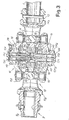
- the accompanying drawing illustrates a wide-angle constant-velocity joint of an essentially conventional kind.
- Reference 1 denotes a tubular component of a telescopic shaft ending in a wide-angle constant-velocity joint 5.
- the telescopic shaft 1 may be fitted with a protective sheath.
- the constant-velocity joint 5, of the wide-angle kind comprises a power coupling member 9, for input to or output from the joint, forming a grooved seat 9A for connection to a drive member with which the constant-velocity joint is combined. Integral with the member 9 is the base 10A of a fork 10 forming part of said joint 5.
- the telescopic shaft 1 is linked to a member 12 integral with the base 14A of a fork 14 forming part of said constant-velocity joint.
- Each of the two forks 10 and 14 comprises a terminal crosspiece 10C, 14C, from which a spherical head 10B, 14B extends, the said two spherical heads being opposite each other.
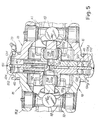
- the constant-velocity joint also includes a central core 16 that is made in two parts which are basically symmetrical about a plane at right angles to the overall axis of the joint considered with the input and output components of the members 9 and 12 in line with each other.
- the said two parts of the member 16 are connected together by welding at 16S, or by other means, such as bolts.
- the central core 16 has two opposing pairs of projections 16A, the projections of each pair forming seats of rotation for a corresponding spider, and each spider 18 is further hinged to the corresponding fork 10, 14, respectively, described above.
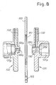
- This divider 150 separates the abovementioned discoidal housing (similar to the housing 24) into two separate housings 124 communicating with each other through said window 151 and through a number of through holes 152.
- the grease nipple 28 therefore supplies both housings 124.
- Each of said two housings accommodates one of the two constraint members 120, which can slide in a guided manner between the corresponding surface of the divider 150 and the corresponding wall 124A or 124B or the corresponding laminar ring 40, if present.
- Each of said constraint members 120 has a number of radial holes 130 (for example three) which allow communication between the housing 124 and the corresponding seat 120A, to allow lubrication between the seat 120A and the corresponding head 10B or 14B.
- One of the two constraint members 120 (that on the right-hand side viewing the drawing) has a cylindrical protrusion 120C with a large through hole 120E into which the holes 130 lead.
- the other constraint member 120 has in turn a smaller cylindrical protrusion 120F designed to fit into the through hole 120E.
Landscapes
- Engineering & Computer Science (AREA)
- General Engineering & Computer Science (AREA)
- Mechanical Engineering (AREA)
- Pivots And Pivotal Connections (AREA)
- Heating, Cooling, Or Curing Plastics Or The Like In General (AREA)
- Excavating Of Shafts Or Tunnels (AREA)
- Earth Drilling (AREA)
- Prostheses (AREA)
- Golf Clubs (AREA)
Claims (8)
- Weitwinkel-Gleichlaufgelenk, das zwei Gabeln (10, 14), welche die Eingangs- und Ausgangselemente des Gelenks bilden, zwei Gelenkkreuze (18) und einen zentralen Kern umfasst, der zwei Teile umfasst und einen Hohlraum zwischen zwei gegenüberliegenden Wänden (124A, 124B) bildet, jeweils gebildet durch ein entsprechendes Teil der zwei Teile, für eine gleitende Bewegung in einer Transversalebene von zwei im Wesentlichen symmetrischen Begrenzungselementen (120), die jeweilige Sitze (120A) für kugelförmige Köpfe (10B, 14B) an den Enden der Gabeln bilden, wobei die beiden Begrenzungselemente (120) miteinander verbunden sind,
dadurch gekennzeichnet, dass es eine scheibenförmige Trennwand (150) umfasst, welche den Hohlraum in zwei Gehäuse (124) teilt, jedes Begrenzungselement (120) zwischen der scheibenförmigen Trennwand (150) und der entsprechenden Wand der gegenüberliegenden Wände (124A; 124B) des Hohlraums oder einem laminaren Ring (40), der an der Wand (124A; 124B) aufliegt, gleitet. - Gleichlaufgelenk gemäß Anspruch 1, dadurch gekennzeichnet, dass die zwei Begrenzungselemente (120) durch zwei zentrale Vorsprünge (120C, 120F), die ineinander gleiten, verbunden sind, und dass die scheibenförmige Trennwand (150) ein zentrales Fenster (152) aufweist, in dessen Inneren sich die Vorsprünge (120C, 120F) bewegen können.
- Gleichlaufgelenk gemäß Anspruch 1 oder 2, dadurch gekennzeichnet, dass die scheibenförmige Trennwand (150) starr mit dem zentralen Kern (16) verbunden ist.
- Gleichlaufgelenk gemäß Anspruch 1 oder 2 oder 3, dadurch gekennzeichnet, dass die scheibenförmige Trennwand (150) peripher zwischen den zwei Teilen, die den zentralen Kern (16) bilden, gehalten ist, wenn die zwei Teile miteinander verbunden sind.
- Gleichlaufgelenk gemäß einem der vorhergehenden Ansprüche, dadurch gekennzeichnet , dass Durchgangslöcher (130) zur Schmierung der Sitze zwischen jedem Gehäuse (124) und dem Sitz (120A) des Begrenzungselements (120), das in dem Gehäuse aufgenommen ist, gebildet sind.
- Gleichlaufgelenk gemäß einem der vorhergehenden Ansprüche, dadurch gekennzeichnet, dass die zwei Gehäuse (124) durch Löcher (152) in der scheibenförmigen Trennwand (150) in Verbindung stehen, um die Zufuhr von Schmierfett aus einem einzigen Schmiernippel (28) zu ermöglichen.
- Gleichlaufgelenk gemäß einem der vorhergehenden Ansprüche, dadurch gekennzeichnet , dass jedes der Begrenzungselemente (120) einen scheibenförmig geformten Teil aufweist, der auf eine geführte Weise zwischen der entsprechenden Oberfläche der scheibenförmigen Trennwand (150) und der jeweiligen Wand der Wände (124A; 124B) oder dem entsprechenden laminaren Ring (40) gleitet.
- Gleichlaufgelenk gemäß den Ansprüchen 2 und 7, dadurch gekennzeichnet, dass der zentrale Vorsprung (120C, 120F) jedes Begrenzungselements (120) zentral hinsichtlich des entsprechenden scheibenförmig geformten Bereichs angeordnet ist.
Applications Claiming Priority (2)
| Application Number | Priority Date | Filing Date | Title |
|---|---|---|---|
| IT000002A ITFI20030002A1 (it) | 2003-01-03 | 2003-01-03 | Giunto omocinetico a grande angolazione, con disposizione per ridurre le sollecitazioni degli organi interni |
| ITFI20030002 | 2003-01-03 |
Publications (2)
| Publication Number | Publication Date |
|---|---|
| EP1435467A1 EP1435467A1 (de) | 2004-07-07 |
| EP1435467B1 true EP1435467B1 (de) | 2010-05-05 |
Family
ID=32500552
Family Applications (1)
| Application Number | Title | Priority Date | Filing Date |
|---|---|---|---|
| EP04425002A Expired - Lifetime EP1435467B1 (de) | 2003-01-03 | 2004-01-02 | Weitwinkelgleichlaufgelenkeinrichtung zur Verminderung der Spannung der inneren Elementen |
Country Status (6)
| Country | Link |
|---|---|
| US (1) | US7011583B2 (de) |
| EP (1) | EP1435467B1 (de) |
| AT (1) | ATE467060T1 (de) |
| DE (1) | DE602004026948D1 (de) |
| ES (1) | ES2341003T3 (de) |
| IT (1) | ITFI20030002A1 (de) |
Families Citing this family (3)
| Publication number | Priority date | Publication date | Assignee | Title |
|---|---|---|---|---|
| ITFI20030001A1 (it) * | 2003-01-03 | 2004-07-04 | Edi Bondioli | Giunto omocinetico a grande angolazione perfezionato per prolungare il tempo di lubrificazione e ridurre la dispersione di lubrificante |
| US8920249B2 (en) * | 2013-03-15 | 2014-12-30 | Paccar Inc | High angle universal coupling with constant or near constant characteristics |
| IT201900009702A1 (it) * | 2019-06-21 | 2020-12-21 | Italgiunti Srl | Doppio giunto cardanico |
Family Cites Families (6)
| Publication number | Priority date | Publication date | Assignee | Title |
|---|---|---|---|---|
| FR818717A (fr) | 1937-03-04 | 1937-10-02 | Perfectionnement apporté aux joints universels homocinétiques | |
| DE3921242C1 (de) | 1989-06-29 | 1990-06-21 | Jean Walterscheid Gmbh, 5204 Lohmar, De | |
| JP3193975B2 (ja) | 1992-12-15 | 2001-07-30 | 光洋精工株式会社 | ステアリング装置用等速ジョイント |
| US5419740A (en) | 1992-03-16 | 1995-05-30 | Toyota Jidosha Kabushiki Kaisha | Constant velocity joint having centering disk bearing eccentric socket |
| IT1314869B1 (it) | 2000-07-24 | 2003-01-16 | Edi Bondioli | Giunto omocinetico a grande angolazione con lubrificazione a bagnod'olio, per trasmissioni cardaniche. |
| DE10120432A1 (de) | 2001-04-26 | 2002-11-14 | Walterscheid Gmbh Gkn | Zentriertes Doppelkreuzgelenk |
-
2003
- 2003-01-03 IT IT000002A patent/ITFI20030002A1/it unknown
- 2003-12-30 US US10/748,382 patent/US7011583B2/en not_active Expired - Lifetime
-
2004
- 2004-01-02 DE DE602004026948T patent/DE602004026948D1/de not_active Expired - Lifetime
- 2004-01-02 ES ES04425002T patent/ES2341003T3/es not_active Expired - Lifetime
- 2004-01-02 AT AT04425002T patent/ATE467060T1/de not_active IP Right Cessation
- 2004-01-02 EP EP04425002A patent/EP1435467B1/de not_active Expired - Lifetime
Also Published As
| Publication number | Publication date |
|---|---|
| US20040152524A1 (en) | 2004-08-05 |
| ITFI20030002A1 (it) | 2004-07-04 |
| ATE467060T1 (de) | 2010-05-15 |
| US7011583B2 (en) | 2006-03-14 |
| DE602004026948D1 (de) | 2010-06-17 |
| EP1435467A1 (de) | 2004-07-07 |
| ES2341003T3 (es) | 2010-06-14 |
Similar Documents
| Publication | Publication Date | Title |
|---|---|---|
| US5954586A (en) | Constant velocity joint | |
| EP1366307B1 (de) | nockenstabzentriermechanismus | |
| US5062730A (en) | Universal joint | |
| EP0584400A3 (de) | Wellenkupplung | |
| CA2932041A1 (en) | Coupling | |
| EP1267095B1 (de) | Umlaufrädervorrichtung zur Geschwindigkeitsreduzierung der Motorausgangswelle | |
| US4565541A (en) | Small deflection coupling for oscillating shafts | |
| CA2454663C (en) | Wide-angle constant-velocity joint, with arrangement for reducing the stresses of the internal members | |
| EP1435467B1 (de) | Weitwinkelgleichlaufgelenkeinrichtung zur Verminderung der Spannung der inneren Elementen | |
| US20190093710A1 (en) | Coupling | |
| JP2021511472A (ja) | シャフトカップリング | |
| US4136532A (en) | Drive shaft | |
| WO2021212338A1 (zh) | 一种动力总成和车辆 | |
| DE69713113D1 (de) | Antriebskupplung | |
| CN220185644U (zh) | 一种伸缩型万向联轴器 | |
| US6846242B1 (en) | Universal joint assembly | |
| JP2010019363A (ja) | オルダム継手 | |
| KR20230157038A (ko) | 등속조인트용 커넥터 및 이를 구비한 등속조인트 | |
| CN107327509B (zh) | 万向联轴器 | |
| JP2697764B2 (ja) | 自在軸継手 | |
| KR100428049B1 (ko) | 풀리형 등속조인트 | |
| WO2023047414A1 (en) | Self-aligning coupler | |
| JPS6343028A (ja) | 自在継手 | |
| US9915292B2 (en) | Tripod type constant-velocity joint | |
| RU2407928C1 (ru) | Кардан синхронный |
Legal Events
| Date | Code | Title | Description |
|---|---|---|---|
| PUAI | Public reference made under article 153(3) epc to a published international application that has entered the european phase |
Free format text: ORIGINAL CODE: 0009012 |
|
| AK | Designated contracting states |
Kind code of ref document: A1 Designated state(s): AT BE BG CH CY CZ DE DK EE ES FI FR GB GR HU IE IT LI LU MC NL PT RO SE SI SK TR |
|
| AX | Request for extension of the european patent |
Extension state: AL LT LV MK |
|
| 17P | Request for examination filed |
Effective date: 20040522 |
|
| 17Q | First examination report despatched |
Effective date: 20040804 |
|
| AKX | Designation fees paid |
Designated state(s): AT BE BG CH CY CZ DE DK EE ES FI FR GB GR HU IE IT LI LU MC NL PT RO SE SI SK TR |
|
| GRAP | Despatch of communication of intention to grant a patent |
Free format text: ORIGINAL CODE: EPIDOSNIGR1 |
|
| GRAS | Grant fee paid |
Free format text: ORIGINAL CODE: EPIDOSNIGR3 |
|
| GRAA | (expected) grant |
Free format text: ORIGINAL CODE: 0009210 |
|
| AK | Designated contracting states |
Kind code of ref document: B1 Designated state(s): AT BE BG CH CY CZ DE DK EE ES FI FR GB GR HU IE IT LI LU MC NL PT RO SE SI SK TR |
|
| REG | Reference to a national code |
Ref country code: GB Ref legal event code: FG4D |
|
| REG | Reference to a national code |
Ref country code: CH Ref legal event code: EP |
|
| REG | Reference to a national code |
Ref country code: IE Ref legal event code: FG4D |
|
| REG | Reference to a national code |
Ref country code: ES Ref legal event code: FG2A Ref document number: 2341003 Country of ref document: ES Kind code of ref document: T3 |
|
| REF | Corresponds to: |
Ref document number: 602004026948 Country of ref document: DE Date of ref document: 20100617 Kind code of ref document: P |
|
| REG | Reference to a national code |
Ref country code: NL Ref legal event code: VDEP Effective date: 20100505 |
|
| PG25 | Lapsed in a contracting state [announced via postgrant information from national office to epo] |
Ref country code: SE Free format text: LAPSE BECAUSE OF FAILURE TO SUBMIT A TRANSLATION OF THE DESCRIPTION OR TO PAY THE FEE WITHIN THE PRESCRIBED TIME-LIMIT Effective date: 20100505 Ref country code: NL Free format text: LAPSE BECAUSE OF FAILURE TO SUBMIT A TRANSLATION OF THE DESCRIPTION OR TO PAY THE FEE WITHIN THE PRESCRIBED TIME-LIMIT Effective date: 20100505 |
|
| PG25 | Lapsed in a contracting state [announced via postgrant information from national office to epo] |
Ref country code: SI Free format text: LAPSE BECAUSE OF FAILURE TO SUBMIT A TRANSLATION OF THE DESCRIPTION OR TO PAY THE FEE WITHIN THE PRESCRIBED TIME-LIMIT Effective date: 20100505 Ref country code: FI Free format text: LAPSE BECAUSE OF FAILURE TO SUBMIT A TRANSLATION OF THE DESCRIPTION OR TO PAY THE FEE WITHIN THE PRESCRIBED TIME-LIMIT Effective date: 20100505 Ref country code: AT Free format text: LAPSE BECAUSE OF FAILURE TO SUBMIT A TRANSLATION OF THE DESCRIPTION OR TO PAY THE FEE WITHIN THE PRESCRIBED TIME-LIMIT Effective date: 20100505 |
|
| PG25 | Lapsed in a contracting state [announced via postgrant information from national office to epo] |
Ref country code: GR Free format text: LAPSE BECAUSE OF FAILURE TO SUBMIT A TRANSLATION OF THE DESCRIPTION OR TO PAY THE FEE WITHIN THE PRESCRIBED TIME-LIMIT Effective date: 20100806 Ref country code: CY Free format text: LAPSE BECAUSE OF FAILURE TO SUBMIT A TRANSLATION OF THE DESCRIPTION OR TO PAY THE FEE WITHIN THE PRESCRIBED TIME-LIMIT Effective date: 20100505 |
|
| PG25 | Lapsed in a contracting state [announced via postgrant information from national office to epo] |
Ref country code: PT Free format text: LAPSE BECAUSE OF FAILURE TO SUBMIT A TRANSLATION OF THE DESCRIPTION OR TO PAY THE FEE WITHIN THE PRESCRIBED TIME-LIMIT Effective date: 20100906 Ref country code: EE Free format text: LAPSE BECAUSE OF FAILURE TO SUBMIT A TRANSLATION OF THE DESCRIPTION OR TO PAY THE FEE WITHIN THE PRESCRIBED TIME-LIMIT Effective date: 20100505 Ref country code: DK Free format text: LAPSE BECAUSE OF FAILURE TO SUBMIT A TRANSLATION OF THE DESCRIPTION OR TO PAY THE FEE WITHIN THE PRESCRIBED TIME-LIMIT Effective date: 20100505 |
|
| PG25 | Lapsed in a contracting state [announced via postgrant information from national office to epo] |
Ref country code: SK Free format text: LAPSE BECAUSE OF FAILURE TO SUBMIT A TRANSLATION OF THE DESCRIPTION OR TO PAY THE FEE WITHIN THE PRESCRIBED TIME-LIMIT Effective date: 20100505 Ref country code: RO Free format text: LAPSE BECAUSE OF FAILURE TO SUBMIT A TRANSLATION OF THE DESCRIPTION OR TO PAY THE FEE WITHIN THE PRESCRIBED TIME-LIMIT Effective date: 20100505 Ref country code: CZ Free format text: LAPSE BECAUSE OF FAILURE TO SUBMIT A TRANSLATION OF THE DESCRIPTION OR TO PAY THE FEE WITHIN THE PRESCRIBED TIME-LIMIT Effective date: 20100505 Ref country code: BE Free format text: LAPSE BECAUSE OF FAILURE TO SUBMIT A TRANSLATION OF THE DESCRIPTION OR TO PAY THE FEE WITHIN THE PRESCRIBED TIME-LIMIT Effective date: 20100505 |
|
| PLBE | No opposition filed within time limit |
Free format text: ORIGINAL CODE: 0009261 |
|
| STAA | Information on the status of an ep patent application or granted ep patent |
Free format text: STATUS: NO OPPOSITION FILED WITHIN TIME LIMIT |
|
| 26N | No opposition filed |
Effective date: 20110208 |
|
| REG | Reference to a national code |
Ref country code: DE Ref legal event code: R097 Ref document number: 602004026948 Country of ref document: DE Effective date: 20110207 |
|
| PG25 | Lapsed in a contracting state [announced via postgrant information from national office to epo] |
Ref country code: MC Free format text: LAPSE BECAUSE OF NON-PAYMENT OF DUE FEES Effective date: 20110131 |
|
| REG | Reference to a national code |
Ref country code: CH Ref legal event code: PL |
|
| GBPC | Gb: european patent ceased through non-payment of renewal fee |
Effective date: 20110102 |
|
| REG | Reference to a national code |
Ref country code: FR Ref legal event code: ST Effective date: 20110930 |
|
| REG | Reference to a national code |
Ref country code: IE Ref legal event code: MM4A |
|
| PG25 | Lapsed in a contracting state [announced via postgrant information from national office to epo] |
Ref country code: LI Free format text: LAPSE BECAUSE OF NON-PAYMENT OF DUE FEES Effective date: 20110131 Ref country code: CH Free format text: LAPSE BECAUSE OF NON-PAYMENT OF DUE FEES Effective date: 20110131 Ref country code: FR Free format text: LAPSE BECAUSE OF NON-PAYMENT OF DUE FEES Effective date: 20110131 |
|
| PG25 | Lapsed in a contracting state [announced via postgrant information from national office to epo] |
Ref country code: GB Free format text: LAPSE BECAUSE OF NON-PAYMENT OF DUE FEES Effective date: 20110102 |
|
| PG25 | Lapsed in a contracting state [announced via postgrant information from national office to epo] |
Ref country code: IE Free format text: LAPSE BECAUSE OF NON-PAYMENT OF DUE FEES Effective date: 20110102 |
|
| PG25 | Lapsed in a contracting state [announced via postgrant information from national office to epo] |
Ref country code: LU Free format text: LAPSE BECAUSE OF NON-PAYMENT OF DUE FEES Effective date: 20110102 |
|
| PG25 | Lapsed in a contracting state [announced via postgrant information from national office to epo] |
Ref country code: TR Free format text: LAPSE BECAUSE OF FAILURE TO SUBMIT A TRANSLATION OF THE DESCRIPTION OR TO PAY THE FEE WITHIN THE PRESCRIBED TIME-LIMIT Effective date: 20100505 Ref country code: BG Free format text: LAPSE BECAUSE OF FAILURE TO SUBMIT A TRANSLATION OF THE DESCRIPTION OR TO PAY THE FEE WITHIN THE PRESCRIBED TIME-LIMIT Effective date: 20100805 |
|
| PG25 | Lapsed in a contracting state [announced via postgrant information from national office to epo] |
Ref country code: HU Free format text: LAPSE BECAUSE OF FAILURE TO SUBMIT A TRANSLATION OF THE DESCRIPTION OR TO PAY THE FEE WITHIN THE PRESCRIBED TIME-LIMIT Effective date: 20100505 |
|
| PGFP | Annual fee paid to national office [announced via postgrant information from national office to epo] |
Ref country code: DE Payment date: 20200325 Year of fee payment: 17 Ref country code: IT Payment date: 20191128 Year of fee payment: 17 Ref country code: ES Payment date: 20200203 Year of fee payment: 17 |
|
| REG | Reference to a national code |
Ref country code: DE Ref legal event code: R119 Ref document number: 602004026948 Country of ref document: DE |
|
| PG25 | Lapsed in a contracting state [announced via postgrant information from national office to epo] |
Ref country code: DE Free format text: LAPSE BECAUSE OF NON-PAYMENT OF DUE FEES Effective date: 20210803 |
|
| REG | Reference to a national code |
Ref country code: ES Ref legal event code: FD2A Effective date: 20220413 |
|
| PG25 | Lapsed in a contracting state [announced via postgrant information from national office to epo] |
Ref country code: IT Free format text: LAPSE BECAUSE OF NON-PAYMENT OF DUE FEES Effective date: 20210102 |
|
| PG25 | Lapsed in a contracting state [announced via postgrant information from national office to epo] |
Ref country code: ES Free format text: LAPSE BECAUSE OF NON-PAYMENT OF DUE FEES Effective date: 20210103 |