EP1435449B1 - Apparat mit pulsierender Verbrennung und verteilter Zündung - Google Patents
Apparat mit pulsierender Verbrennung und verteilter Zündung Download PDFInfo
- Publication number
- EP1435449B1 EP1435449B1 EP03258153A EP03258153A EP1435449B1 EP 1435449 B1 EP1435449 B1 EP 1435449B1 EP 03258153 A EP03258153 A EP 03258153A EP 03258153 A EP03258153 A EP 03258153A EP 1435449 B1 EP1435449 B1 EP 1435449B1
- Authority
- EP
- European Patent Office
- Prior art keywords
- combustion
- vessel
- engine
- length
- ignition
- Prior art date
- Legal status (The legal status is an assumption and is not a legal conclusion. Google has not performed a legal analysis and makes no representation as to the accuracy of the status listed.)
- Expired - Lifetime
Links
- 238000002485 combustion reaction Methods 0.000 title claims abstract description 56
- 238000005474 detonation Methods 0.000 claims abstract description 12
- 238000004200 deflagration Methods 0.000 claims description 7
- 238000011144 upstream manufacturing Methods 0.000 claims description 5
- 238000010892 electric spark Methods 0.000 claims 1
- 238000010894 electron beam technology Methods 0.000 claims 1
- 230000000977 initiatory effect Effects 0.000 abstract description 3
- 239000007789 gas Substances 0.000 description 15
- 239000000446 fuel Substances 0.000 description 10
- 238000007599 discharging Methods 0.000 description 8
- 239000000203 mixture Substances 0.000 description 7
- 239000003999 initiator Substances 0.000 description 4
- 230000007704 transition Effects 0.000 description 4
- QVGXLLKOCUKJST-UHFFFAOYSA-N atomic oxygen Chemical compound [O] QVGXLLKOCUKJST-UHFFFAOYSA-N 0.000 description 3
- 230000000903 blocking effect Effects 0.000 description 3
- 238000005516 engineering process Methods 0.000 description 3
- 238000010304 firing Methods 0.000 description 3
- 239000001301 oxygen Substances 0.000 description 3
- 229910052760 oxygen Inorganic materials 0.000 description 3
- 238000007789 sealing Methods 0.000 description 3
- GQPLMRYTRLFLPF-UHFFFAOYSA-N Nitrous Oxide Chemical compound [O-][N+]#N GQPLMRYTRLFLPF-UHFFFAOYSA-N 0.000 description 2
- 238000004891 communication Methods 0.000 description 2
- 230000000694 effects Effects 0.000 description 2
- 239000007858 starting material Substances 0.000 description 2
- 230000000153 supplemental effect Effects 0.000 description 2
- 239000000567 combustion gas Substances 0.000 description 1
- 230000000295 complement effect Effects 0.000 description 1
- 230000006835 compression Effects 0.000 description 1
- 238000007906 compression Methods 0.000 description 1
- 238000009826 distribution Methods 0.000 description 1
- 238000012986 modification Methods 0.000 description 1
- 230000004048 modification Effects 0.000 description 1
- 239000001272 nitrous oxide Substances 0.000 description 1
- 239000007800 oxidant agent Substances 0.000 description 1
- 230000000149 penetrating effect Effects 0.000 description 1
- 238000001228 spectrum Methods 0.000 description 1
- 230000001960 triggered effect Effects 0.000 description 1
- 238000009827 uniform distribution Methods 0.000 description 1
Images
Classifications
-
- F—MECHANICAL ENGINEERING; LIGHTING; HEATING; WEAPONS; BLASTING
- F02—COMBUSTION ENGINES; HOT-GAS OR COMBUSTION-PRODUCT ENGINE PLANTS
- F02K—JET-PROPULSION PLANTS
- F02K7/00—Plants in which the working fluid is used in a jet only, i.e. the plants not having a turbine or other engine driving a compressor or a ducted fan; Control thereof
- F02K7/02—Plants in which the working fluid is used in a jet only, i.e. the plants not having a turbine or other engine driving a compressor or a ducted fan; Control thereof the jet being intermittent, i.e. pulse-jet
-
- F—MECHANICAL ENGINEERING; LIGHTING; HEATING; WEAPONS; BLASTING
- F02—COMBUSTION ENGINES; HOT-GAS OR COMBUSTION-PRODUCT ENGINE PLANTS
- F02C—GAS-TURBINE PLANTS; AIR INTAKES FOR JET-PROPULSION PLANTS; CONTROLLING FUEL SUPPLY IN AIR-BREATHING JET-PROPULSION PLANTS
- F02C3/00—Gas-turbine plants characterised by the use of combustion products as the working fluid
- F02C3/14—Gas-turbine plants characterised by the use of combustion products as the working fluid characterised by the arrangement of the combustion chamber in the plant
- F02C3/16—Gas-turbine plants characterised by the use of combustion products as the working fluid characterised by the arrangement of the combustion chamber in the plant the combustion chambers being formed at least partly in the turbine rotor or in an other rotating part of the plant
- F02C3/165—Gas-turbine plants characterised by the use of combustion products as the working fluid characterised by the arrangement of the combustion chamber in the plant the combustion chambers being formed at least partly in the turbine rotor or in an other rotating part of the plant the combustion chamber contributes to the driving force by creating reactive thrust
-
- F—MECHANICAL ENGINEERING; LIGHTING; HEATING; WEAPONS; BLASTING
- F02—COMBUSTION ENGINES; HOT-GAS OR COMBUSTION-PRODUCT ENGINE PLANTS
- F02C—GAS-TURBINE PLANTS; AIR INTAKES FOR JET-PROPULSION PLANTS; CONTROLLING FUEL SUPPLY IN AIR-BREATHING JET-PROPULSION PLANTS
- F02C5/00—Gas-turbine plants characterised by the working fluid being generated by intermittent combustion
- F02C5/02—Gas-turbine plants characterised by the working fluid being generated by intermittent combustion characterised by the arrangement of the combustion chamber in the chamber in the plant
- F02C5/04—Gas-turbine plants characterised by the working fluid being generated by intermittent combustion characterised by the arrangement of the combustion chamber in the chamber in the plant the combustion chambers being formed at least partly in the turbine rotor
-
- F—MECHANICAL ENGINEERING; LIGHTING; HEATING; WEAPONS; BLASTING
- F02—COMBUSTION ENGINES; HOT-GAS OR COMBUSTION-PRODUCT ENGINE PLANTS
- F02C—GAS-TURBINE PLANTS; AIR INTAKES FOR JET-PROPULSION PLANTS; CONTROLLING FUEL SUPPLY IN AIR-BREATHING JET-PROPULSION PLANTS
- F02C5/00—Gas-turbine plants characterised by the working fluid being generated by intermittent combustion
- F02C5/10—Gas-turbine plants characterised by the working fluid being generated by intermittent combustion the working fluid forming a resonating or oscillating gas column, i.e. the combustion chambers having no positively actuated valves, e.g. using Helmholtz effect
- F02C5/11—Gas-turbine plants characterised by the working fluid being generated by intermittent combustion the working fluid forming a resonating or oscillating gas column, i.e. the combustion chambers having no positively actuated valves, e.g. using Helmholtz effect using valveless combustion chambers
-
- F—MECHANICAL ENGINEERING; LIGHTING; HEATING; WEAPONS; BLASTING
- F02—COMBUSTION ENGINES; HOT-GAS OR COMBUSTION-PRODUCT ENGINE PLANTS
- F02K—JET-PROPULSION PLANTS
- F02K3/00—Plants including a gas turbine driving a compressor or a ducted fan
- F02K3/02—Plants including a gas turbine driving a compressor or a ducted fan in which part of the working fluid by-passes the turbine and combustion chamber
- F02K3/04—Plants including a gas turbine driving a compressor or a ducted fan in which part of the working fluid by-passes the turbine and combustion chamber the plant including ducted fans, i.e. fans with high volume, low pressure outputs, for augmenting the jet thrust, e.g. of double-flow type
- F02K3/06—Plants including a gas turbine driving a compressor or a ducted fan in which part of the working fluid by-passes the turbine and combustion chamber the plant including ducted fans, i.e. fans with high volume, low pressure outputs, for augmenting the jet thrust, e.g. of double-flow type with front fan
-
- F—MECHANICAL ENGINEERING; LIGHTING; HEATING; WEAPONS; BLASTING
- F02—COMBUSTION ENGINES; HOT-GAS OR COMBUSTION-PRODUCT ENGINE PLANTS
- F02K—JET-PROPULSION PLANTS
- F02K7/00—Plants in which the working fluid is used in a jet only, i.e. the plants not having a turbine or other engine driving a compressor or a ducted fan; Control thereof
- F02K7/02—Plants in which the working fluid is used in a jet only, i.e. the plants not having a turbine or other engine driving a compressor or a ducted fan; Control thereof the jet being intermittent, i.e. pulse-jet
- F02K7/075—Plants in which the working fluid is used in a jet only, i.e. the plants not having a turbine or other engine driving a compressor or a ducted fan; Control thereof the jet being intermittent, i.e. pulse-jet with multiple pulse-jet engines
Definitions
- This invention relates to pulse combustion devices, and more particularly to pulsejet engines and hybrid pulse combustion and turbine engines.
- Pulse detonation engines represent areas of particular development.
- fuel and oxidizer e.g. oxygen-containing gas such as air
- oxidizer e.g. oxygen-containing gas such as air
- the valve is closed and an igniter is utilized to detonate the charge (either directly or through a deflagration to detonation transition).
- a detonation wave propagates toward the outlet at supersonic speed causing substantial combustion of the fuel/air mixture before the mixture can be substantially driven from the outlet.
- the result of the combustion is to rapidly elevate pressure within the chamber before substantial gas can escape inertially through the outlet.
- the effect of this inertial confinement is to produce near constant volume combustion as distinguished, for example, from constant pressure combustion.
- Detonation ignition has several disadvantages. Achieving reliable detonation imposes complexity costs. These arise from a need for close control over parameters such as pressure, temperature, fuel droplet size, and fuel distribution as well as related use of complex initiator and combustor geometry, and the addition of supplemental accelerants such as oxygen. There may be operational drawbacks including noise and vibration, high operating temperatures and pressures, and nitrous oxide emission.
- PDE technology has a variety of applications.
- a traditional application is pulsejet engines. Certain recent applications involve use in turbine or hybrid engines.
- U.S. Patent No. 6,442,930 and earlier patents identify several hybrid applications. These include uses as thrust augmentors and as replacements for conventional continuous constant pressure turbine combustors.
- a further example of a PDE is disclosed in US-A-2557198.
- one aspect of the invention is a pulse combustion device having a vessel with a gas inlet and a gas outlet.
- a valve opens and closes the inlet to admit a charge of gas.
- the device includes means for producing a distributed ignition of the gas along a flow path within the vessel. Combustion occurs substantially via deflagration.
- the ignition may be multipoint, continuous, and/or multi-continuous.
- a number of such devices may be utilized as a combustor of a turbine engine.
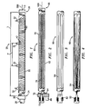
- FIG. 1 shows a device 20 having a containment tube 22 extending along a central longitudinal axis 500 from an inlet end 24 to an outlet end 26.
- the inlet end is coupled to a fuel/air conduit 28 by a valve 30.
- a series of igniters 32 are positioned at various locations along the tube.
- the tube has an overall length L and the igniters are positioned at an exemplary pitch P.
- the tube interior has a characteristic transverse dimension identified as a diameter D.
- each igniter When triggered, each igniter produces a deflagration pulse 40 which propagates a flame front radially outward from an associated ignition point 42 at a subsonic speed(e.g., under about 2,000 feet per second (fps) (610 m/s) and typically in the vicinity of 1,000 fps (305 m/s).
- a subsonic speed e.g., under about 2,000 feet per second (fps) (610 m/s) and typically in the vicinity of 1,000 fps (305 m/s).
- FIG. 1 illustrates but a rudimentary example of a multi-igniter, multi-point ignition system.
- Various embellishments may be made involving the positioning of the igniters and their trigger timing to achieve desired combustion parameters.
- there may be continuous or multi-continuous ignition.
- FIG. 2 shows a device 60 with a tube 62 that may be otherwise similar to the tube 22 of FIG. 1.
- the tube 62 has inlet and outlet ends 64 and 66.
- the inlet end is in selective communication with a fuel/air conduit 68 via a valve 70.
- an initiator 72 is also carried by or otherwise coupled to the valve 70 for emitting an energy beam 74.
- the energy beam extends from the inlet end all the way to the outlet end and beyond.
- the beam acts as a distributed linear ignition source along the axis 500.
- the resulting deflagration flame front 76 moves essentially radially away from the axis 500 and thus needs to propagate only one half of the diameter D to achieve substantial combustion.
- Such initiation is particularly useful with combustion chamber configurations that provide the beam with a straight path through a substantial portion of the chamber.
- FIG. 3 shows a device 80 with an initiator 82 that emits several substantially parallel beams 84 to further reduce relative combustion time.
- FIG. 4 shows a device 90 with an initiator 92 that sweeps a beam 94 through a volume of the chamber at a sufficiently high sweep speed to further reduce the characteristic combustion time.
- the devices may operate in a broad performance envelope.
- Exemplary operating pressure ratios may be between 2:1 and 30:1.
- the low end of the spectrum might be typical for ram-fed applications and the high end for pre-compression applications.
- Basic applications include use as pulsejet engines.
- inlet air is fed into the device due to the movement of the vehicle through the air and the exhaust expelled from the outlet as thrust.
- Applications for such pulse combustion devices further include a variety of uses in turbine or hybrid engines.
- One area of hybrid engines involves utilizing the devices in place of conventional combustor technology.
- the pulse combustion devices may be located in one or more rings about the engine.
- the rings may be located on a rotating carousel, the rotation of which passes each device through a first portion of a rotation during which the device is charged and to a second portion in which it is discharged, with combustion occurring between.
- the rotation may be driven by one of the turbine's spools or by tangential diversion of gases discharged by the devices.
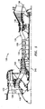
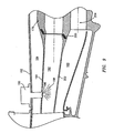
- FIG. 5 shows a turbofan engine 120 having a duct 122 and a core 124.
- the duct is supported relative to the core by vanes 126.
- a fan 128 drives a bypass portion along a first flow path radially between the duct and the core and core portion along a second flowpath through the core.
- a compressor section 130 having alternating rings of rotor blades and stator vanes compresses the core air and delivers it further downstream to a combustor section 132 where it is mixed with fuel and combusted.
- a combustor bypass portion of the core air may bypass the combustor and be mixed with the portion flowing through the combustor in a mixing duct 134 downstream of the combustor. Downstream of the mixing duct, a turbine section 136 is driven by the mixing duct output to in turn drive the compressor and fan. An augmentor 138 may be located downstream of the turbine.
- the exemplary combustor includes a ring of combustion tubes 150 which may be operated as pulse combustion tubes such as those of FIGS. 1-4. Although advantageously operated as pulse deflagration tubes, a similar structure may potentially be used with pulse detonation tubes.
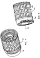
- the tubes are mounted in a carousel structure 152 (FIGS. 6 and 7) for rotation about the engine central longitudinal axis 510.
- Each exemplary tube 150 (FIG. 8) has a forward upstream inlet end 153 and an aft downstream outlet end 154. The tube inlet ends are proximate an aft, downstream portion of a fixed manifold 160.
- the exemplary carousel includes a number of disks 170, 172, 174, and 176 from fore to aft.
- the carousel forms a third free spool in addition to the high and low spools of the turbine/compressor combination.
- the disks Proximate their outboard peripheries, the disks have apertures 178 into which the tubes 150 are secured.
- Disk platforms 180 combine to form a cylindrical inboard wall of the local core flow path.
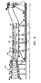
- the manifold 160 splits the core flow into three portions in inboard, intermediate, and outboard manifold sections 180, 182 and 184 (FIG. 9).
- the manifold has a circumferential array of fuel injectors 190 mounted in an outer wall 192 of the core and penetrating the outer section 184 to a wall 194 separating the sections 182 and 184.
- An injector outlet 196 is positioned to introduce fuel 198 into the intermediate section 182 where it mixes with that portion of the core air passing through the intermediate section.
- the manifold intermediate section 182 is in communication with a transiently aligned group of the tubes 150.
- a sealing system 200 is provided on a downstream end of the wall 194 and a downstream end of a wall 202 separating the sections 180 and 188.
- the sealing system cooperates with the leading disk 170 to pass the fuel air mixture from the manifold section 182 into the tubes 150 when the tubes are aligned with the charging sector.
- the inboard manifold section 180 passes an inboard portion of the core air to the carousel where it may pass through inboard apertures 204 in the disks to bypass the tubes 150.
- the manifold outboard section 184 passes an outboard portion of the core air around the outer peripheries of the disks to bypass the tubes. Once in the carousel, there may be mixing of these two bypass portions with between the disks.
- the manifold has a blocking element 220 (FIG. 10) which cooperates with the leading disk 170 to seal the inlet end of the tube 150 to create a combustion chamber.
- the combustion chamber is bounded by a vessel created by the tube 150, a small portion of the disk 170 thereahead and an aft blocking surface portion of the element 220. Ignition and discharge may occur when each tube is so sealed.
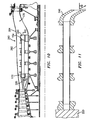
- the exemplary manifold separates the core air flow into inboard and outboard flows bypassing the tubes in similar fashion to the bypassing flows of the charging sector. Combustion gases discharge from the tube outlet 154 encounter turning vanes 240 which may be unitarily formed with the aft carousel disk 176.
- an equal number of turning vanes 240 are alternatingly interspersed with the tubes 150. Adjacent vanes divert the discharge from the tubes by an angle ⁇ (FIG. 11) relative to the tube axis and local longitudinal centerplane of the engine. In the exemplary embodiment, this diversion applies sufficient torque to the carousel to rotate the carousel at a desired rotational speed. In an exemplary three spool engine, an exemplary steady state rotational speed of the carousel is 2,000-18,000 RPM. The specific operating range will be influenced by engine dimensional considerations in view of carousel structural integrity and the number of charge/discharge cycles per rotation.
- a narrower range of 6,000-12,000 target RPM is likely with the lower third of this range more likely for a two cycle/rotation engine and the upper third for a one cycle/rotation engine. In operation, these speeds will likely be substantially lower than the high spool speed and approximately the same or moderately lower than the low spool speed.
- An initial rotation may be provided by the engine starter motor or by a dedicated starter motor for the combustor.
- the discharge flow is mixed with the combustor bypass flows before encountering the turbine.
- an outboard portion of the flow passing over the trailing disk 176 may at least partially mix with a discharge flow along the vanes 240.
- An inboard portion passing through the apertures 204 in the trailing disk may mix further downstream in the mixing duct 136.
- the core outer wall 192 has a locally radially elevated section or hump 260 (FIG. 10) with a first portion 262 extending aft from near a forward end of the carousel and a second portion 264 extending further rearward along a forward portion of the mixing duct 136. Portions of the outer wall fore and aft of the hump are of more even radial position about the circumference of the core.
- the hump is associated with the discharging sector.
- the hump is shaped to drive a large percentage of the core bypass flow volume to the vicinity of the firing combustor tubes.
- the hump provides a non-uniform cross section for increased cross sectional flow area in the firing discharge zone of a mixing plane.
- the large volume of relatively cool core air that bypasses the combustor tube mixes with and reduces the temperature of the exhaust effluents.
- the cross-section of the duct transitions to a uniform cross-section prior to reaching the turbine face.
- the transition geometry forces core bypass and exhaust gas mixing and uniform distribution of the mixed gases around the circumference of the duct.
- the hump and mixing duct geometry and the volume between the turning vanes and the turbine face serve three primary functions: 1) to diffuse the high velocity exhaust gases to a useable pressure rise compatible with the engine through flow requirements; 2) to mix out and transition localized hot, high velocity exhaust effluents and cool core by-pass air to a uniform (or nearly uniform) pressure, velocity and temperature flow of gas at the turbine face; and 3) act as a pressure pulse dampener to smooth out the flow presented to the turbine.
- An exemplary hump may be disposed helically in accordance with the helical velocity component of exhaust gases exiting the combustor.
- combustion tubes there may be between 4 and 60 combustion tubes, more narrowly, 20 and 40.
- Exemplary tube lengths(and the approximately similar combustion chamber lengths) are between 6 inches (15 cm) and 40 inches (102 cm), more narrowly, 12 inches (30 cm) and 30 inches (76 cm).
- the exemplary tube cross sectional areas are between 1.0 inch 2 (6.5 cm 2 ) and 20 inch 2 (129 cm 2 ) more narrowly, 2.0 inch 2 (12.9 cm 2 ) and 8 inch 2 (51.6 cm 2 ).
- An exemplary discharging sector is between 5° and 120°, more narrowly, 10° and 100°.
- the key limitation regarding the charging sector is the time required to charge the combustion tubes at a given radius from the engine centerline and rotational speed.
- an exemplary discharging sector would be 80-120° with the substantially complementary charging sector being 240-280°.
- the magnitude of the pressure pulses from the individual combustion tubes is minimized by the apparent high firing frequency (e.g., 1000 Hz to 6000 Hz) provided by the rotating tube pack.
- the pressure pulses may overlap at a relatively uniform peak level resulting in a quasi-steady state effluent pressure. Additional viscous dampening of any residual small cyclical pressure variations occurs in the volume of the duct as the core bypass and combustor tube exhaust gases mix together. The mixed gases are then expanded through the turbine.
- alternative embodiments involve providing the blocking portion with a u-shaped passageway, one leg of which communicates with the tube inlet and the other leg of which communicates with an auxiliary at least partially longitudinal exhaust conduit.
- exhaust conduit may be mounted to the carousel or fixed and external thereto.
- the combustion products are expelled both from the combustion tube outlet and from the inlet.
- the latter flow of combustion products may flow through the exhaust conduit and, for example, join the remainder at an outlet of such exhaust conduit proximate the combustion tube outlet. This reduces the pressure loads on the seal between the manifold and carousel.
Landscapes
- Engineering & Computer Science (AREA)
- Chemical & Material Sciences (AREA)
- Combustion & Propulsion (AREA)
- Mechanical Engineering (AREA)
- General Engineering & Computer Science (AREA)
- Fluidized-Bed Combustion And Resonant Combustion (AREA)
- Air Bags (AREA)
Claims (16)
- Pulsverbrennungsvorrichtung, aufweisend:einen Kessel (22) mit einem Gaseinlass (24) und einem Gasauslass (26); undein Ventil (30) zum Öffnen und Schließen des Einlass zum Einlassen einer Ladung von Gas;gekennzeichnet durcheine Einrichtung (32; 72; 82; 92) zum Erzeugen einer verteilten Entzündung des Gases entlang einem Strömungsweg in dem Kessel, wodurch eine Verbrennung im Wesentlichen über Entflammung erfolgt.
- Vorrichtung nach Anspruch 1, wobei der Kessel (22) eine Länge entlang einem Strömungsweg zwischen dem Einlass und dem Auslass hat, wobei die Länge mindestens 1,5 mal einer Quadratwurzel einer mittleren Querschnittsfläche ist.
- Vorrichtung nach Anspruch 1, wobei der Kessel (22) zu einem Hauptteil aus einem Rohr mit im Wesentlichen gleichförmigen Kreisquerschnitt ist, das eine Länge von mindestens 1,5 mal einen charakteristischen Innendurchmesser hat.
- Vorrichtung nach Anspruch 1, 2 oder 3, die unter einem Betriebsdruckverhältnis von zwischen 2:1 und 30:1 arbeitet.
- Turbobläsermaschine (120), aufweisend:einen Bläser(128);einen Verdichter (130);eine Pulsverbrennungsbrennkammereinrichtung (132), die eine Mehrzahl von Pulsverbrennungsvorrichtungen gemäß Anspruch 1 aufweist, die Luft von dem Verdichter erhält und Verbrennungsgase abgibt, wobei jede der Vorrichtungen aufweist:eine längliche Brennkammer (150), wobei jede einen solchen Gaseinlass (153) und einen solchen Gasauslass (154) hat; undwobei die Zündeinrichtung eine verteilte Entzündung des Gases entlang einem Strömungsweg in der Brennkammer erzeugt, wobei die Entzündung ohne Detonation erfolgt;wobei die Maschine ferner eine Turbine (136) aufweist, welche Verbrennungsgase empfängt und den Verdichter und den Bläser antreibt.
- Maschine nach Anspruch 5, welche unter Bedingungen eines Betriebsdrucksverhältnis von zwischen 2:1 und 20:1 arbeitet.
- Maschine nach Anspruch 5, welche unter Bedingungen eines Betriebsdruckverhältnisses von zwischen 10:1 und 20:1 arbeitet.
- Maschine nach einem der Ansprüche 5 bis 7, aufweisend mindestens acht derartiger Brennkammern,
- Maschine nach einem der Ansprüche 5 bis 8, wobei die Brennkammern (150) jeweils ein Rohr aufweisen und wobei die Rohre für arbeitsmäßige Rotation als eine Einheit um eine zentrale Längsachse (510) der Maschine getragen sind.
- Pulsverbrennungsvorrichtung nach Anspruch 1, wobei die Zündeinrichtung aus der Gruppe ausgewählt ist, die besteht aus:eine Mehrzahl von Zündeinrichtungen (32), die an einer Mehrzahl von Positionen von strömungsaufwärts nach strömungsabwärts entlang dem Kessel angeordnet sind; undeine Energiequelle (72; 82; 92), die mindestens einen Strahl in einer im wesentlichen strömungsaufwärtigen oder strömungsabwärtigen Richtung lenkt.
- Vorrichtung nach Anspruch 10, wobei die Zündeinrichtungen (32) elektrische Funken-Zündeinrichtungen sind.
- Vorrichtung nach Anspruch 10 oder 11, wobei mindestens eine erste derartige Zündeinrichtung (32) in einem strömungsaufwärtigen 1/3 einer Länge des Kessels und eine zweite derartige Zündeinrichtung (32) in einem strömungsabwärigen 1/3 der Länge des Kessels (22) ist.
- Vorrichtung nach Anspruch 10, 11 oder 12, wobei mindestens drei solche Zündeinrichtungen (32) mit Abständen, die nicht größer als 1/2 einer Länge des Kessels (22) sind, angeordnet sind.
- Vorrichtung nach einem der Ansprüche 10 bis 13, wobei mindestens vier derartigen Zündeinrichtungen (32) mit Abständen, die nicht größer als 1/3 einer Länge des Kessels (22) sind, vorhanden sind.
- Vorrichtung nach Anspruch 10, wobei die Energiequelle (72; 82; 92) aus der Gruppe gewählt ist, die besteht aus Lasern, Mikrowellenquellen, Elektronenstrahlquellen und Plasmastrahlquellen.
- Vorrichtung nach einem der Ansprüche 10 bis 15, welche unter Bedingungen eines Betriebsdruckverhältnisses zwischen 2:1 und 20:1 arbeitet.
Applications Claiming Priority (2)
| Application Number | Priority Date | Filing Date | Title |
|---|---|---|---|
| US10/334,019 US7047724B2 (en) | 2002-12-30 | 2002-12-30 | Combustion ignition |
| US334019 | 2002-12-30 |
Publications (2)
| Publication Number | Publication Date |
|---|---|
| EP1435449A1 EP1435449A1 (de) | 2004-07-07 |
| EP1435449B1 true EP1435449B1 (de) | 2006-07-26 |
Family
ID=32507369
Family Applications (1)
| Application Number | Title | Priority Date | Filing Date |
|---|---|---|---|
| EP03258153A Expired - Lifetime EP1435449B1 (de) | 2002-12-30 | 2003-12-24 | Apparat mit pulsierender Verbrennung und verteilter Zündung |
Country Status (4)
| Country | Link |
|---|---|
| US (2) | US7047724B2 (de) |
| EP (1) | EP1435449B1 (de) |
| AT (1) | ATE334307T1 (de) |
| DE (1) | DE60307033T2 (de) |
Families Citing this family (61)
| Publication number | Priority date | Publication date | Assignee | Title |
|---|---|---|---|---|
| FR2829528B1 (fr) * | 2001-09-07 | 2004-02-27 | Bernard Gilbert Macarez | Pulsomoteur-turbomoteur a impulsion-turbine a gaz a chambre de combustion impulsionnelle et a detente de bouffees |
| US7367194B2 (en) * | 2003-02-12 | 2008-05-06 | Ishikawajima-Harima Heavy Industries Co., Ltd. | Pulse detonation engine system for driving turbine |
| FR2855556B1 (fr) * | 2003-05-28 | 2007-04-13 | Mbda France | Moteur a detonations pulsees |
| US7124573B2 (en) * | 2004-03-18 | 2006-10-24 | General Electric Company | Rotary pulse detonation system with aerodynamic detonation passages for use in a gas turbine engine |
| US20050210862A1 (en) * | 2004-03-25 | 2005-09-29 | Paterro Von Friedrich C | Quantum jet turbine propulsion system |
| US7131260B2 (en) * | 2004-06-18 | 2006-11-07 | General Electric Company | Multiple detonation initiator for frequency multiplied pulsed detonation combustion |
| US7228683B2 (en) * | 2004-07-21 | 2007-06-12 | General Electric Company | Methods and apparatus for generating gas turbine engine thrust using a pulse detonator |
| US7080504B2 (en) * | 2004-07-23 | 2006-07-25 | Northrop Grumman Corporation | Laser augmented turbojet propulsion system |
| US7328570B2 (en) * | 2004-09-01 | 2008-02-12 | General Electric Company | Pulse detonation system for a gas turbine engine having multiple spools |
| US20060053801A1 (en) * | 2004-09-15 | 2006-03-16 | Orlando Robert J | Cooling system for gas turbine engine having improved core system |
| US7093446B2 (en) * | 2004-09-15 | 2006-08-22 | General Electric Company | Gas turbine engine having improved core system |
| US7096674B2 (en) * | 2004-09-15 | 2006-08-29 | General Electric Company | High thrust gas turbine engine with improved core system |
| US7278256B2 (en) * | 2004-11-08 | 2007-10-09 | United Technologies Corporation | Pulsed combustion engine |
| US7637096B2 (en) * | 2004-11-25 | 2009-12-29 | Rolls-Royce Plc | Pulse jet engine having pressure sensor means for controlling fuel delivery into a combustion chamber |
| US7500348B2 (en) * | 2005-03-24 | 2009-03-10 | United Technologies Corporation | Pulse combustion device |
| US7448200B2 (en) * | 2005-03-24 | 2008-11-11 | United Technologies Corporation | Pulse combustion device |
| US7685806B2 (en) * | 2005-12-29 | 2010-03-30 | General Electric Company | Method and apparatus for supersonic and shock noise reduction in aircraft engines using pneumatic corrugations |
| US20090320439A1 (en) * | 2006-01-31 | 2009-12-31 | General Electric Company | Pulsed detonation combustor cleaning device and method of operation |
| KR100785611B1 (ko) | 2006-07-14 | 2007-12-12 | 산 지 타이 | 제트 터빈용 회전체 및 그 제조 방법 |
| US7937945B2 (en) | 2006-10-27 | 2011-05-10 | Kinde Sr Ronald August | Combining a series of more efficient engines into a unit, or modular units |
| US20080155959A1 (en) * | 2006-12-22 | 2008-07-03 | General Electric Company | Detonation combustor to turbine transition piece for hybrid engine |
| US8146371B2 (en) * | 2007-12-21 | 2012-04-03 | United Technologies Corporation | Direct induction combustor/generator |
| US20090165438A1 (en) * | 2007-12-26 | 2009-07-02 | Occhipinti Anthony C | Pulse detonation engine |
| DE102008028208B4 (de) * | 2008-06-09 | 2012-03-22 | Deutsches Zentrum für Luft- und Raumfahrt e.V. | Brennkammervorrichtung und Verfahren zu deren Betrieb |
| US8205433B2 (en) * | 2008-08-21 | 2012-06-26 | Lockheed Martin Corporation | Pulse detonation/deflagration apparatus and related methods for enhancing DDT wave production |
| US8438834B2 (en) * | 2009-03-30 | 2013-05-14 | Alliant Techsystems Inc. | Helical cross flow (HCF) pulse detonation engine |
| US20100251992A1 (en) * | 2009-04-06 | 2010-10-07 | Davis Frank S | Radial pulsed rotary internal combustion engine |
| US8429893B2 (en) | 2009-08-11 | 2013-04-30 | Northrop Grumman Corporation | Airflow modulation for dual mode combined cycle propulsion systems |
| US20120102916A1 (en) * | 2010-10-29 | 2012-05-03 | General Electric Company | Pulse Detonation Combustor Including Combustion Chamber Cooling Assembly |
| WO2012061742A1 (en) | 2010-11-05 | 2012-05-10 | ThermoChem Recovery International | Solids circulation system and method for capture and conversion of reactive solids |
| US8539752B2 (en) * | 2010-11-30 | 2013-09-24 | General Electric Company | Integrated deflagration-to-detonation obstacles and cooling fluid flow |
| US8650856B2 (en) * | 2010-12-10 | 2014-02-18 | General Electric Company | Fluidic deflagration-to-detonation initiation obstacles |
| WO2013049368A1 (en) | 2011-09-27 | 2013-04-04 | Thermochem Recovery International, Inc. | System and method for syngas clean-up |
| US9140456B2 (en) * | 2011-12-01 | 2015-09-22 | General Electric Company | Variable initiation location system for pulse detonation combustor |
| US20130139486A1 (en) * | 2011-12-01 | 2013-06-06 | General Electric Company | Variable initiation location system for pulse detonation combustor |
| US20140338348A1 (en) * | 2011-12-16 | 2014-11-20 | Daniel Guy Pomerleau | Rotary pulse detonation engine |
| KR20150032911A (ko) * | 2012-07-24 | 2015-03-30 | 브렌트 웨이-테 이 | 내부 폭발 엔진, 그것을 포함하는 하이브리드 엔진, 및 그것의 제조 및 사용 방법 |
| US9021783B2 (en) * | 2012-10-12 | 2015-05-05 | United Technologies Corporation | Pulse detonation engine having a scroll ejector attenuator |
| WO2015138033A1 (en) * | 2013-12-31 | 2015-09-17 | Hill James D | Inlet manifold for multi-tube pulse detonation engine |
| FI127525B (en) * | 2014-01-08 | 2018-08-15 | Finno Energy Oy | System and method for generating electrical energy |
| US9869190B2 (en) | 2014-05-30 | 2018-01-16 | General Electric Company | Variable-pitch rotor with remote counterweights |
| US10072510B2 (en) | 2014-11-21 | 2018-09-11 | General Electric Company | Variable pitch fan for gas turbine engine and method of assembling the same |
| US11225913B2 (en) | 2015-02-19 | 2022-01-18 | Raytheon Technologies Corporation | Method of providing turbine engines with different thrust ratings |
| US10100653B2 (en) | 2015-10-08 | 2018-10-16 | General Electric Company | Variable pitch fan blade retention system |
| US20170114752A1 (en) * | 2015-10-27 | 2017-04-27 | Honda Patents & Technologies North America, Llc | Standing wave compressor pulsejet engine |
| US10240794B2 (en) | 2016-02-11 | 2019-03-26 | Rolls-Royce Corporation | Thermal and thrust management in dynamic pressure exchangers |
| CA3014874C (en) | 2016-02-16 | 2019-03-19 | Thermochem Recovery International, Inc. | Two-stage energy-integrated product gas generation system and method |
| ES2923073T3 (es) | 2016-03-25 | 2022-09-22 | Thermochem Recovery Int Inc | Sistema de generación de producto gaseoso integrada en energía de tres fases |
| US10526965B2 (en) * | 2016-04-29 | 2020-01-07 | Rolls-Royce Corporation | Ignition system for constant volume combustor |
| US20180010800A1 (en) * | 2016-06-14 | 2018-01-11 | Adithya Ananth NAGESH | Shock compression based supersonic combustor |
| US10364398B2 (en) | 2016-08-30 | 2019-07-30 | Thermochem Recovery International, Inc. | Method of producing product gas from multiple carbonaceous feedstock streams mixed with a reduced-pressure mixing gas |
| EP3619471B1 (de) * | 2017-04-30 | 2021-02-24 | King Abdullah University Of Science And Technology | Verbrennungsmotor mit automatisch angesteuerter plasmaaktuator für übergang vom deflagrations- zum detonationsverbrennungsraum und verfahren zum betrieb eines solchen motors |
| US9920926B1 (en) | 2017-07-10 | 2018-03-20 | Thermochem Recovery International, Inc. | Pulse combustion heat exchanger system and method |
| US10099200B1 (en) | 2017-10-24 | 2018-10-16 | Thermochem Recovery International, Inc. | Liquid fuel production system having parallel product gas generation |
| US20210140641A1 (en) * | 2019-11-13 | 2021-05-13 | General Electric Company | Method and system for rotating detonation combustion |
| US11555157B2 (en) | 2020-03-10 | 2023-01-17 | Thermochem Recovery International, Inc. | System and method for liquid fuel production from carbonaceous materials using recycled conditioned syngas |
| US11466223B2 (en) | 2020-09-04 | 2022-10-11 | Thermochem Recovery International, Inc. | Two-stage syngas production with separate char and product gas inputs into the second stage |
| CN113153569B (zh) * | 2021-04-27 | 2022-10-28 | 西北工业大学 | 一种平稳排气的多管脉冲爆震发动机 |
| US11674435B2 (en) | 2021-06-29 | 2023-06-13 | General Electric Company | Levered counterweight feathering system |
| US11795964B2 (en) | 2021-07-16 | 2023-10-24 | General Electric Company | Levered counterweight feathering system |
| US12510249B2 (en) * | 2023-06-20 | 2025-12-30 | Pratt & Whitney Canada Corp. | Auxiliary power unit with pulse detonation combustion |
Family Cites Families (56)
| Publication number | Priority date | Publication date | Assignee | Title |
|---|---|---|---|---|
| DE690569C (de) | 1937-03-09 | 1940-04-29 | Holzwarth Gasturbinen G M B H | Verfahren und Vorrichtung zur Aufladung langgestreckter Verpuffungskammern, insbesondere fuer Brennkraftturbinen, mit gasfoermigen Brennstoffen oder Brennstoffe tragenden Gasen |
| US2395403A (en) * | 1939-03-06 | 1946-02-26 | Daniel And Florence Guggenheim | Rotatable combustion apparatus for aircraft |
| US2479829A (en) * | 1943-10-23 | 1949-08-23 | Daniel And Florence Guggenheim | Rotating combustion chamber with continuous rearward discharge |
| US2442610A (en) * | 1946-03-05 | 1948-06-01 | Nat Lead Co | Precipitation of hydrous vanadium oxide |
| US2612750A (en) * | 1946-07-26 | 1952-10-07 | Daniel And Florence Guggenheim | Rotatable combustion chamber |
| US2630676A (en) * | 1947-01-20 | 1953-03-10 | Donald W Seifert | Axial flow jet motor with rotating combustion products generator and turbine |
| US2630677A (en) * | 1947-01-20 | 1953-03-10 | Donald W Seifert | Axial flow jet motor with reversely rotating continuous combustion type combustion products generator and turbine |
| US2612021A (en) * | 1947-05-12 | 1952-09-30 | Zuhn Arthur Attwood | Continuous combustion type rotating combustion products generator and turbine |
| US2557198A (en) * | 1947-05-21 | 1951-06-19 | American Locomotive Co | Gas turbine |
| US2543864A (en) * | 1947-12-22 | 1951-03-06 | John A Melenric | Jet propulsion unit with rotatab combustion chamber |
| US2579049A (en) * | 1949-02-04 | 1951-12-18 | Nathan C Price | Rotating combustion products generator and turbine of the continuous combustion type |
| GB710252A (en) | 1950-05-25 | 1954-06-09 | Napier & Son Ltd | Improvements in or relating to power plants incorporating gas turbines |
| US2748564A (en) * | 1951-03-16 | 1956-06-05 | Snecma | Intermittent combustion gas turbine engine |
| US2930196A (en) * | 1951-03-30 | 1960-03-29 | Cornell Aeronautical Labor Inc | Valved intermittent combustion reaction engine |
| US2609663A (en) * | 1951-07-21 | 1952-09-09 | United Aircraft Corp | Rotatable combustion apparatus for aligning individual flame tubes with access partsor manholes |
| US2680949A (en) * | 1951-10-18 | 1954-06-15 | Butler Frank David | Internal-combustion turbine having rotating combustion chambers |
| US2736369A (en) * | 1953-06-22 | 1956-02-28 | James A Hall | Auto-rotative combustion heater |
| GB756288A (en) | 1953-10-15 | 1956-09-05 | Snecma | Improvements relating to thrust augmenters for rocket motors |
| US2836958A (en) * | 1954-02-17 | 1958-06-03 | Iii John A Ward | Jet power plant with unobstructed rotating combustion chamber |
| US2888803A (en) * | 1954-08-30 | 1959-06-02 | Pon Lemuel | Intermittent combustion turbine engine |
| US3321911A (en) * | 1965-02-12 | 1967-05-30 | Myles Tommie Lynn | Gas turbine engine with rotating combustion chamber |
| US3469396A (en) * | 1966-07-02 | 1969-09-30 | Shigeru Onishi | Gas turbine |
| US3362157A (en) * | 1966-09-28 | 1968-01-09 | Navy Usa | Gas turbine engine with rotary regenerator and rotating constant volume combustion chambers |
| US3417564A (en) * | 1967-04-19 | 1968-12-24 | John G. Call | Jet engine with relatively rotatable combustion means, intake manifold and exhaust manifold |
| US3557551A (en) * | 1968-09-26 | 1971-01-26 | Gordon Keith Colin Campbell | Gas turbine engine with rotating combustion chamber |
| US3792584A (en) * | 1972-02-16 | 1974-02-19 | Boeing Co | Increased or variable bypass ratio engines |
| US3798900A (en) * | 1972-11-22 | 1974-03-26 | Us Navy | Central igniter for rotatable combustion chamber |
| US3791139A (en) * | 1972-12-26 | 1974-02-12 | Ns Co | Turbine engine with valved, rotating combustion chamber |
| US4314444A (en) * | 1980-06-23 | 1982-02-09 | Battelle Memorial Institute | Heating apparatus |
| AT379217B (de) * | 1982-10-27 | 1985-12-10 | Lorenz Edmund | Impulsgesteuerte gasturbine |
| JPS6159108A (ja) * | 1984-08-29 | 1986-03-26 | Toshiba Corp | パルス燃焼装置 |
| US5138831A (en) * | 1991-03-07 | 1992-08-18 | Cowan Sr Howard H | Air cooled rotary combustion engine |
| US5218816A (en) * | 1992-01-28 | 1993-06-15 | General Electric Company | Seal exit flow discourager |
| US5419118A (en) * | 1994-01-19 | 1995-05-30 | Universal Propulsion Company, Inc. | Multi-stage rocket motors |
| US5473885A (en) * | 1994-06-24 | 1995-12-12 | Lockheed Corporation | Pulse detonation engine |
| US5557926A (en) * | 1994-06-24 | 1996-09-24 | Lockheed-Martin | Pulse detonation apparatus with inner and outer Spherical valves |
| US5579633A (en) * | 1994-06-24 | 1996-12-03 | Lockheed Martin Corporation | Annular pulse detonation apparatus and method |
| US5494004A (en) * | 1994-09-23 | 1996-02-27 | Lockheed Corporation | On line pulsed detonation/deflagration soot blower |
| US5800153A (en) * | 1995-07-07 | 1998-09-01 | Mark DeRoche | Repetitive detonation generator |
| GB2313161B (en) * | 1996-05-14 | 2000-05-31 | Rolls Royce Plc | Gas turbine engine casing |
| US5937635A (en) * | 1996-11-27 | 1999-08-17 | Lockheed Martin Corporation | Pulse detonation igniter for pulse detonation chambers |
| US5864517A (en) * | 1997-03-21 | 1999-01-26 | Adroit Systems, Inc. | Pulsed combustion acoustic wave generator |
| DE19850812A1 (de) | 1997-11-06 | 2000-08-24 | Max Tobler | Brennkammer einer Gasturbine oder eines Strahltriebwerks und Verfahren zu deren Betrieb |
| US5960625A (en) * | 1998-08-21 | 1999-10-05 | Zdvorak, Sr.; Edward H. | Constant volume combustion turbine with plurality flow turbine wheels |
| US6442930B1 (en) * | 2000-03-31 | 2002-09-03 | General Electric Company | Combined cycle pulse detonation turbine engine |
| US6477829B1 (en) * | 2000-05-09 | 2002-11-12 | Lockheed Martin Corporation | Combined cycle pulse combustion/gas turbine engine |
| US6449939B1 (en) * | 2000-05-26 | 2002-09-17 | Rolls-Royce Corporation | Pulsed detonation engine wave rotor |
| US6349538B1 (en) * | 2000-06-13 | 2002-02-26 | Lockheed Martin Corporation | Annular liquid fueled pulse detonation engine |
| US6584761B2 (en) * | 2000-12-15 | 2003-07-01 | Lockheed Martin Corporation | MAPP gas fuel for flight vehicles having pulse detonation engines and method of use |
| US6484492B2 (en) * | 2001-01-09 | 2002-11-26 | General Electric Company | Magnetohydrodynamic flow control for pulse detonation engines |
| US6505462B2 (en) | 2001-03-29 | 2003-01-14 | General Electric Company | Rotary valve for pulse detonation engines |
| US6516605B1 (en) * | 2001-06-15 | 2003-02-11 | General Electric Company | Pulse detonation aerospike engine |
| US6584765B1 (en) * | 2001-12-21 | 2003-07-01 | United Technologies Corporation | Pulse detonation engine having an aerodynamic valve |
| US6877310B2 (en) * | 2002-03-27 | 2005-04-12 | General Electric Company | Shock wave reflector and detonation chamber |
| US6813878B2 (en) * | 2002-12-11 | 2004-11-09 | General Electric Company | Methods and apparatus for operating gas turbine engines |
| US6886325B2 (en) * | 2002-12-30 | 2005-05-03 | United Technologies Corporation | Pulsed combustion engine |
-
2002
- 2002-12-30 US US10/334,019 patent/US7047724B2/en not_active Expired - Fee Related
-
2003
- 2003-06-27 US US10/608,238 patent/US7100360B2/en not_active Expired - Fee Related
- 2003-12-24 DE DE60307033T patent/DE60307033T2/de not_active Expired - Lifetime
- 2003-12-24 EP EP03258153A patent/EP1435449B1/de not_active Expired - Lifetime
- 2003-12-24 AT AT03258153T patent/ATE334307T1/de not_active IP Right Cessation
Also Published As
| Publication number | Publication date |
|---|---|
| US7100360B2 (en) | 2006-09-05 |
| US7047724B2 (en) | 2006-05-23 |
| ATE334307T1 (de) | 2006-08-15 |
| EP1435449A1 (de) | 2004-07-07 |
| US20050000205A1 (en) | 2005-01-06 |
| US20040123583A1 (en) | 2004-07-01 |
| DE60307033T2 (de) | 2006-12-21 |
| DE60307033D1 (de) | 2006-09-07 |
Similar Documents
| Publication | Publication Date | Title |
|---|---|---|
| EP1435449B1 (de) | Apparat mit pulsierender Verbrennung und verteilter Zündung | |
| US6901738B2 (en) | Pulsed combustion turbine engine | |
| US6886325B2 (en) | Pulsed combustion engine | |
| US7278256B2 (en) | Pulsed combustion engine | |
| JP4705727B2 (ja) | 複合サイクル・パルスデトネーション・タービンエンジン | |
| US8650856B2 (en) | Fluidic deflagration-to-detonation initiation obstacles | |
| CN100507253C (zh) | 一种多管脉冲爆震燃烧室及其起爆方法 | |
| US6931858B2 (en) | Rotating pulse detonation system for a gas turbine engine | |
| US11149954B2 (en) | Multi-can annular rotating detonation combustor | |
| US6889505B2 (en) | Pulse detonation system for a gas turbine engine | |
| WO2018147933A1 (en) | Rotating detonation combustor | |
| CN109028144A (zh) | 整体涡流旋转爆震推进系统 | |
| US20180355792A1 (en) | Annular throats rotating detonation combustor | |
| US12092336B2 (en) | Turbine engine assembly including a rotating detonation combustor | |
| EP3056713B1 (de) | Abgasmischer für wellenrotoranordnung | |
| EP1862660A1 (de) | Gasturbine mit pulsierender Verbrennung | |
| US7124573B2 (en) | Rotary pulse detonation system with aerodynamic detonation passages for use in a gas turbine engine | |
| US6904750B2 (en) | Integral pulse detonation system for a gas turbine engine | |
| EP1435440B1 (de) | Pulsierender Verbrennungsmotor | |
| EP1435447B1 (de) | Gasturbine mit pulsierender Verbrennung | |
| US7634904B2 (en) | Methods and apparatus to facilitate generating power from a turbine engine | |
| US20080127630A1 (en) | Turbine for application to pulse detonation combustion system and engine containing the turbine |
Legal Events
| Date | Code | Title | Description |
|---|---|---|---|
| PUAI | Public reference made under article 153(3) epc to a published international application that has entered the european phase |
Free format text: ORIGINAL CODE: 0009012 |
|
| AK | Designated contracting states |
Kind code of ref document: A1 Designated state(s): AT BE BG CH CY CZ DE DK EE ES FI FR GB GR HU IE IT LI LU MC NL PT RO SE SI SK TR |
|
| AX | Request for extension of the european patent |
Extension state: AL LT LV MK |
|
| 17P | Request for examination filed |
Effective date: 20040915 |
|
| 17Q | First examination report despatched |
Effective date: 20041011 |
|
| AKX | Designation fees paid |
Designated state(s): AT BE BG CH CY CZ DE DK EE ES FI FR GB GR HU IE IT LI LU MC NL PT RO SE SI SK TR |
|
| GRAP | Despatch of communication of intention to grant a patent |
Free format text: ORIGINAL CODE: EPIDOSNIGR1 |
|
| GRAS | Grant fee paid |
Free format text: ORIGINAL CODE: EPIDOSNIGR3 |
|
| GRAA | (expected) grant |
Free format text: ORIGINAL CODE: 0009210 |
|
| AK | Designated contracting states |
Kind code of ref document: B1 Designated state(s): AT BE BG CH CY CZ DE DK EE ES FI FR GB GR HU IE IT LI LU MC NL PT RO SE SI SK TR |
|
| PG25 | Lapsed in a contracting state [announced via postgrant information from national office to epo] |
Ref country code: IT Free format text: LAPSE BECAUSE OF FAILURE TO SUBMIT A TRANSLATION OF THE DESCRIPTION OR TO PAY THE FEE WITHIN THE PRESCRIBED TIME-LIMIT;WARNING: LAPSES OF ITALIAN PATENTS WITH EFFECTIVE DATE BEFORE 2007 MAY HAVE OCCURRED AT ANY TIME BEFORE 2007. THE CORRECT EFFECTIVE DATE MAY BE DIFFERENT FROM THE ONE RECORDED. Effective date: 20060726 Ref country code: SI Free format text: LAPSE BECAUSE OF FAILURE TO SUBMIT A TRANSLATION OF THE DESCRIPTION OR TO PAY THE FEE WITHIN THE PRESCRIBED TIME-LIMIT Effective date: 20060726 Ref country code: NL Free format text: LAPSE BECAUSE OF FAILURE TO SUBMIT A TRANSLATION OF THE DESCRIPTION OR TO PAY THE FEE WITHIN THE PRESCRIBED TIME-LIMIT Effective date: 20060726 Ref country code: FI Free format text: LAPSE BECAUSE OF FAILURE TO SUBMIT A TRANSLATION OF THE DESCRIPTION OR TO PAY THE FEE WITHIN THE PRESCRIBED TIME-LIMIT Effective date: 20060726 Ref country code: CH Free format text: LAPSE BECAUSE OF FAILURE TO SUBMIT A TRANSLATION OF THE DESCRIPTION OR TO PAY THE FEE WITHIN THE PRESCRIBED TIME-LIMIT Effective date: 20060726 Ref country code: BE Free format text: LAPSE BECAUSE OF FAILURE TO SUBMIT A TRANSLATION OF THE DESCRIPTION OR TO PAY THE FEE WITHIN THE PRESCRIBED TIME-LIMIT Effective date: 20060726 Ref country code: RO Free format text: LAPSE BECAUSE OF FAILURE TO SUBMIT A TRANSLATION OF THE DESCRIPTION OR TO PAY THE FEE WITHIN THE PRESCRIBED TIME-LIMIT Effective date: 20060726 Ref country code: AT Free format text: LAPSE BECAUSE OF FAILURE TO SUBMIT A TRANSLATION OF THE DESCRIPTION OR TO PAY THE FEE WITHIN THE PRESCRIBED TIME-LIMIT Effective date: 20060726 Ref country code: LI Free format text: LAPSE BECAUSE OF FAILURE TO SUBMIT A TRANSLATION OF THE DESCRIPTION OR TO PAY THE FEE WITHIN THE PRESCRIBED TIME-LIMIT Effective date: 20060726 Ref country code: SK Free format text: LAPSE BECAUSE OF FAILURE TO SUBMIT A TRANSLATION OF THE DESCRIPTION OR TO PAY THE FEE WITHIN THE PRESCRIBED TIME-LIMIT Effective date: 20060726 Ref country code: CZ Free format text: LAPSE BECAUSE OF FAILURE TO SUBMIT A TRANSLATION OF THE DESCRIPTION OR TO PAY THE FEE WITHIN THE PRESCRIBED TIME-LIMIT Effective date: 20060726 |
|
| REG | Reference to a national code |
Ref country code: GB Ref legal event code: FG4D |
|
| REG | Reference to a national code |
Ref country code: CH Ref legal event code: EP |
|
| REG | Reference to a national code |
Ref country code: IE Ref legal event code: FG4D |
|
| REF | Corresponds to: |
Ref document number: 60307033 Country of ref document: DE Date of ref document: 20060907 Kind code of ref document: P |
|
| PG25 | Lapsed in a contracting state [announced via postgrant information from national office to epo] |
Ref country code: DK Free format text: LAPSE BECAUSE OF FAILURE TO SUBMIT A TRANSLATION OF THE DESCRIPTION OR TO PAY THE FEE WITHIN THE PRESCRIBED TIME-LIMIT Effective date: 20061026 Ref country code: BG Free format text: LAPSE BECAUSE OF FAILURE TO SUBMIT A TRANSLATION OF THE DESCRIPTION OR TO PAY THE FEE WITHIN THE PRESCRIBED TIME-LIMIT Effective date: 20061026 Ref country code: SE Free format text: LAPSE BECAUSE OF FAILURE TO SUBMIT A TRANSLATION OF THE DESCRIPTION OR TO PAY THE FEE WITHIN THE PRESCRIBED TIME-LIMIT Effective date: 20061026 |
|
| PG25 | Lapsed in a contracting state [announced via postgrant information from national office to epo] |
Ref country code: ES Free format text: LAPSE BECAUSE OF FAILURE TO SUBMIT A TRANSLATION OF THE DESCRIPTION OR TO PAY THE FEE WITHIN THE PRESCRIBED TIME-LIMIT Effective date: 20061106 |
|
| PG25 | Lapsed in a contracting state [announced via postgrant information from national office to epo] |
Ref country code: PT Free format text: LAPSE BECAUSE OF FAILURE TO SUBMIT A TRANSLATION OF THE DESCRIPTION OR TO PAY THE FEE WITHIN THE PRESCRIBED TIME-LIMIT Effective date: 20061226 |
|
| PG25 | Lapsed in a contracting state [announced via postgrant information from national office to epo] |
Ref country code: IE Free format text: LAPSE BECAUSE OF NON-PAYMENT OF DUE FEES Effective date: 20061228 |
|
| PG25 | Lapsed in a contracting state [announced via postgrant information from national office to epo] |
Ref country code: MC Free format text: LAPSE BECAUSE OF NON-PAYMENT OF DUE FEES Effective date: 20061231 |
|
| NLV1 | Nl: lapsed or annulled due to failure to fulfill the requirements of art. 29p and 29m of the patents act | ||
| ET | Fr: translation filed | ||
| PLBE | No opposition filed within time limit |
Free format text: ORIGINAL CODE: 0009261 |
|
| STAA | Information on the status of an ep patent application or granted ep patent |
Free format text: STATUS: NO OPPOSITION FILED WITHIN TIME LIMIT |
|
| 26N | No opposition filed |
Effective date: 20070427 |
|
| PG25 | Lapsed in a contracting state [announced via postgrant information from national office to epo] |
Ref country code: GR Free format text: LAPSE BECAUSE OF FAILURE TO SUBMIT A TRANSLATION OF THE DESCRIPTION OR TO PAY THE FEE WITHIN THE PRESCRIBED TIME-LIMIT Effective date: 20061027 |
|
| PG25 | Lapsed in a contracting state [announced via postgrant information from national office to epo] |
Ref country code: EE Free format text: LAPSE BECAUSE OF FAILURE TO SUBMIT A TRANSLATION OF THE DESCRIPTION OR TO PAY THE FEE WITHIN THE PRESCRIBED TIME-LIMIT Effective date: 20060726 |
|
| PG25 | Lapsed in a contracting state [announced via postgrant information from national office to epo] |
Ref country code: LU Free format text: LAPSE BECAUSE OF NON-PAYMENT OF DUE FEES Effective date: 20061224 Ref country code: HU Free format text: LAPSE BECAUSE OF FAILURE TO SUBMIT A TRANSLATION OF THE DESCRIPTION OR TO PAY THE FEE WITHIN THE PRESCRIBED TIME-LIMIT Effective date: 20070127 Ref country code: TR Free format text: LAPSE BECAUSE OF FAILURE TO SUBMIT A TRANSLATION OF THE DESCRIPTION OR TO PAY THE FEE WITHIN THE PRESCRIBED TIME-LIMIT Effective date: 20060726 |
|
| PG25 | Lapsed in a contracting state [announced via postgrant information from national office to epo] |
Ref country code: CY Free format text: LAPSE BECAUSE OF FAILURE TO SUBMIT A TRANSLATION OF THE DESCRIPTION OR TO PAY THE FEE WITHIN THE PRESCRIBED TIME-LIMIT Effective date: 20060726 |
|
| PGFP | Annual fee paid to national office [announced via postgrant information from national office to epo] |
Ref country code: FR Payment date: 20081205 Year of fee payment: 6 |
|
| REG | Reference to a national code |
Ref country code: FR Ref legal event code: ST Effective date: 20100831 |
|
| PG25 | Lapsed in a contracting state [announced via postgrant information from national office to epo] |
Ref country code: FR Free format text: LAPSE BECAUSE OF NON-PAYMENT OF DUE FEES Effective date: 20091231 |
|
| REG | Reference to a national code |
Ref country code: DE Ref legal event code: R082 Ref document number: 60307033 Country of ref document: DE Representative=s name: SCHMITT-NILSON SCHRAUD WAIBEL WOHLFROM PATENTA, DE |
|
| REG | Reference to a national code |
Ref country code: DE Ref legal event code: R082 Ref document number: 60307033 Country of ref document: DE Representative=s name: SCHMITT-NILSON SCHRAUD WAIBEL WOHLFROM PATENTA, DE Ref country code: DE Ref legal event code: R081 Ref document number: 60307033 Country of ref document: DE Owner name: UNITED TECHNOLOGIES CORP. (N.D.GES.D. STAATES , US Free format text: FORMER OWNER: UNITED TECHNOLOGIES CORP., HARTFORD, CONN., US |
|
| PGFP | Annual fee paid to national office [announced via postgrant information from national office to epo] |
Ref country code: DE Payment date: 20191119 Year of fee payment: 17 |
|
| PGFP | Annual fee paid to national office [announced via postgrant information from national office to epo] |
Ref country code: GB Payment date: 20191122 Year of fee payment: 17 |
|
| REG | Reference to a national code |
Ref country code: DE Ref legal event code: R119 Ref document number: 60307033 Country of ref document: DE |
|
| GBPC | Gb: european patent ceased through non-payment of renewal fee |
Effective date: 20201224 |
|
| PG25 | Lapsed in a contracting state [announced via postgrant information from national office to epo] |
Ref country code: DE Free format text: LAPSE BECAUSE OF NON-PAYMENT OF DUE FEES Effective date: 20210701 Ref country code: GB Free format text: LAPSE BECAUSE OF NON-PAYMENT OF DUE FEES Effective date: 20201224 |