EP1435328B1 - Zusammensetzung aus lösbaren Teilpaletten - Google Patents
Zusammensetzung aus lösbaren Teilpaletten Download PDFInfo
- Publication number
- EP1435328B1 EP1435328B1 EP03004695A EP03004695A EP1435328B1 EP 1435328 B1 EP1435328 B1 EP 1435328B1 EP 03004695 A EP03004695 A EP 03004695A EP 03004695 A EP03004695 A EP 03004695A EP 1435328 B1 EP1435328 B1 EP 1435328B1
- Authority
- EP
- European Patent Office
- Prior art keywords
- pallet
- spacers
- preferentially
- range
- pallets
- Prior art date
- Legal status (The legal status is an assumption and is not a legal conclusion. Google has not performed a legal analysis and makes no representation as to the accuracy of the status listed.)
- Expired - Lifetime
Links
Images


Classifications
-
- B—PERFORMING OPERATIONS; TRANSPORTING
- B65—CONVEYING; PACKING; STORING; HANDLING THIN OR FILAMENTARY MATERIAL
- B65D—CONTAINERS FOR STORAGE OR TRANSPORT OF ARTICLES OR MATERIALS, e.g. BAGS, BARRELS, BOTTLES, BOXES, CANS, CARTONS, CRATES, DRUMS, JARS, TANKS, HOPPERS, FORWARDING CONTAINERS; ACCESSORIES, CLOSURES, OR FITTINGS THEREFOR; PACKAGING ELEMENTS; PACKAGES
- B65D19/00—Pallets or like platforms, with or without side walls, for supporting loads to be lifted or lowered
- B65D19/0004—Rigid pallets without side walls
- B65D19/0053—Rigid pallets without side walls the load supporting surface being made of more than one element
- B65D19/0055—Rigid pallets without side walls the load supporting surface being made of more than one element forming a continuous plane contact surface
- B65D19/0067—Rigid pallets without side walls the load supporting surface being made of more than one element forming a continuous plane contact surface the base surface being made of more than one element
- B65D19/0071—Rigid pallets without side walls the load supporting surface being made of more than one element forming a continuous plane contact surface the base surface being made of more than one element forming discontinuous or non-planar contact surfaces
- B65D19/0073—Rigid pallets without side walls the load supporting surface being made of more than one element forming a continuous plane contact surface the base surface being made of more than one element forming discontinuous or non-planar contact surfaces and each contact surface having a stringer-like shape
-
- B—PERFORMING OPERATIONS; TRANSPORTING
- B65—CONVEYING; PACKING; STORING; HANDLING THIN OR FILAMENTARY MATERIAL
- B65D—CONTAINERS FOR STORAGE OR TRANSPORT OF ARTICLES OR MATERIALS, e.g. BAGS, BARRELS, BOTTLES, BOXES, CANS, CARTONS, CRATES, DRUMS, JARS, TANKS, HOPPERS, FORWARDING CONTAINERS; ACCESSORIES, CLOSURES, OR FITTINGS THEREFOR; PACKAGING ELEMENTS; PACKAGES
- B65D2519/00—Pallets or like platforms, with or without side walls, for supporting loads to be lifted or lowered
- B65D2519/00004—Details relating to pallets
- B65D2519/00009—Materials
- B65D2519/00014—Materials for the load supporting surface
- B65D2519/00029—Wood
-
- B—PERFORMING OPERATIONS; TRANSPORTING
- B65—CONVEYING; PACKING; STORING; HANDLING THIN OR FILAMENTARY MATERIAL
- B65D—CONTAINERS FOR STORAGE OR TRANSPORT OF ARTICLES OR MATERIALS, e.g. BAGS, BARRELS, BOTTLES, BOXES, CANS, CARTONS, CRATES, DRUMS, JARS, TANKS, HOPPERS, FORWARDING CONTAINERS; ACCESSORIES, CLOSURES, OR FITTINGS THEREFOR; PACKAGING ELEMENTS; PACKAGES
- B65D2519/00—Pallets or like platforms, with or without side walls, for supporting loads to be lifted or lowered
- B65D2519/00004—Details relating to pallets
- B65D2519/00009—Materials
- B65D2519/00049—Materials for the base surface
- B65D2519/00064—Wood
-
- B—PERFORMING OPERATIONS; TRANSPORTING
- B65—CONVEYING; PACKING; STORING; HANDLING THIN OR FILAMENTARY MATERIAL
- B65D—CONTAINERS FOR STORAGE OR TRANSPORT OF ARTICLES OR MATERIALS, e.g. BAGS, BARRELS, BOTTLES, BOXES, CANS, CARTONS, CRATES, DRUMS, JARS, TANKS, HOPPERS, FORWARDING CONTAINERS; ACCESSORIES, CLOSURES, OR FITTINGS THEREFOR; PACKAGING ELEMENTS; PACKAGES
- B65D2519/00—Pallets or like platforms, with or without side walls, for supporting loads to be lifted or lowered
- B65D2519/00004—Details relating to pallets
- B65D2519/00009—Materials
- B65D2519/00084—Materials for the non-integral separating spacer
- B65D2519/00099—Wood
-
- B—PERFORMING OPERATIONS; TRANSPORTING
- B65—CONVEYING; PACKING; STORING; HANDLING THIN OR FILAMENTARY MATERIAL
- B65D—CONTAINERS FOR STORAGE OR TRANSPORT OF ARTICLES OR MATERIALS, e.g. BAGS, BARRELS, BOTTLES, BOXES, CANS, CARTONS, CRATES, DRUMS, JARS, TANKS, HOPPERS, FORWARDING CONTAINERS; ACCESSORIES, CLOSURES, OR FITTINGS THEREFOR; PACKAGING ELEMENTS; PACKAGES
- B65D2519/00—Pallets or like platforms, with or without side walls, for supporting loads to be lifted or lowered
- B65D2519/00004—Details relating to pallets
- B65D2519/00258—Overall construction
- B65D2519/00283—Overall construction of the load supporting surface
- B65D2519/00293—Overall construction of the load supporting surface made of more than one piece
-
- B—PERFORMING OPERATIONS; TRANSPORTING
- B65—CONVEYING; PACKING; STORING; HANDLING THIN OR FILAMENTARY MATERIAL
- B65D—CONTAINERS FOR STORAGE OR TRANSPORT OF ARTICLES OR MATERIALS, e.g. BAGS, BARRELS, BOTTLES, BOXES, CANS, CARTONS, CRATES, DRUMS, JARS, TANKS, HOPPERS, FORWARDING CONTAINERS; ACCESSORIES, CLOSURES, OR FITTINGS THEREFOR; PACKAGING ELEMENTS; PACKAGES
- B65D2519/00—Pallets or like platforms, with or without side walls, for supporting loads to be lifted or lowered
- B65D2519/00004—Details relating to pallets
- B65D2519/00258—Overall construction
- B65D2519/00313—Overall construction of the base surface
- B65D2519/00323—Overall construction of the base surface made of more than one piece
-
- B—PERFORMING OPERATIONS; TRANSPORTING
- B65—CONVEYING; PACKING; STORING; HANDLING THIN OR FILAMENTARY MATERIAL
- B65D—CONTAINERS FOR STORAGE OR TRANSPORT OF ARTICLES OR MATERIALS, e.g. BAGS, BARRELS, BOTTLES, BOXES, CANS, CARTONS, CRATES, DRUMS, JARS, TANKS, HOPPERS, FORWARDING CONTAINERS; ACCESSORIES, CLOSURES, OR FITTINGS THEREFOR; PACKAGING ELEMENTS; PACKAGES
- B65D2519/00—Pallets or like platforms, with or without side walls, for supporting loads to be lifted or lowered
- B65D2519/00004—Details relating to pallets
- B65D2519/00258—Overall construction
- B65D2519/00313—Overall construction of the base surface
- B65D2519/00328—Overall construction of the base surface shape of the contact surface of the base
- B65D2519/00333—Overall construction of the base surface shape of the contact surface of the base contact surface having a stringer-like shape
-
- B—PERFORMING OPERATIONS; TRANSPORTING
- B65—CONVEYING; PACKING; STORING; HANDLING THIN OR FILAMENTARY MATERIAL
- B65D—CONTAINERS FOR STORAGE OR TRANSPORT OF ARTICLES OR MATERIALS, e.g. BAGS, BARRELS, BOTTLES, BOXES, CANS, CARTONS, CRATES, DRUMS, JARS, TANKS, HOPPERS, FORWARDING CONTAINERS; ACCESSORIES, CLOSURES, OR FITTINGS THEREFOR; PACKAGING ELEMENTS; PACKAGES
- B65D2519/00—Pallets or like platforms, with or without side walls, for supporting loads to be lifted or lowered
- B65D2519/00004—Details relating to pallets
- B65D2519/00258—Overall construction
- B65D2519/00368—Overall construction of the non-integral separating spacer
- B65D2519/00373—Overall construction of the non-integral separating spacer whereby at least one spacer is made of one piece
-
- B—PERFORMING OPERATIONS; TRANSPORTING
- B65—CONVEYING; PACKING; STORING; HANDLING THIN OR FILAMENTARY MATERIAL
- B65D—CONTAINERS FOR STORAGE OR TRANSPORT OF ARTICLES OR MATERIALS, e.g. BAGS, BARRELS, BOTTLES, BOXES, CANS, CARTONS, CRATES, DRUMS, JARS, TANKS, HOPPERS, FORWARDING CONTAINERS; ACCESSORIES, CLOSURES, OR FITTINGS THEREFOR; PACKAGING ELEMENTS; PACKAGES
- B65D2519/00—Pallets or like platforms, with or without side walls, for supporting loads to be lifted or lowered
- B65D2519/00004—Details relating to pallets
- B65D2519/00547—Connections
- B65D2519/00552—Structures connecting the constitutive elements of the pallet to each other, i.e. load supporting surface, base surface and/or separate spacer
- B65D2519/00572—Structures connecting the constitutive elements of the pallet to each other, i.e. load supporting surface, base surface and/or separate spacer with separate auxiliary element, e.g. screws, nails, bayonets
-
- B—PERFORMING OPERATIONS; TRANSPORTING
- B65—CONVEYING; PACKING; STORING; HANDLING THIN OR FILAMENTARY MATERIAL
- B65D—CONTAINERS FOR STORAGE OR TRANSPORT OF ARTICLES OR MATERIALS, e.g. BAGS, BARRELS, BOTTLES, BOXES, CANS, CARTONS, CRATES, DRUMS, JARS, TANKS, HOPPERS, FORWARDING CONTAINERS; ACCESSORIES, CLOSURES, OR FITTINGS THEREFOR; PACKAGING ELEMENTS; PACKAGES
- B65D2519/00—Pallets or like platforms, with or without side walls, for supporting loads to be lifted or lowered
- B65D2519/00004—Details relating to pallets
- B65D2519/00736—Details
- B65D2519/00741—Dimensional aspects of the pallet
- B65D2519/00746—Dimensional aspects of the pallet divisible into sub-pallets of smaller dimensions
- B65D2519/00756—Dimensional aspects of the pallet divisible into sub-pallets of smaller dimensions joined together by removable elements, e.g. bands encircling the feed
Definitions
- the present invention relates to a pallet having a load-bearing platform of given dimensions, composed of an integer number of part pallets being arranged adjacent to each other side by side, each part pallet having a load-bearing platform with spacers carrying the load-bearing platform. It additionally relates to the process for making such a pallet.
- Pallets are one of the most common means for storing goods for their transportation. Such palletised products can be transported using standard lifting tools and due to the standardised dimensions of such pallets, storage can be optimised easily. Generally prior to the use of the goods by the customer or prior to the presentation of goods in the stores, the goods are taken off the pallets, but in particular for uses where the goods have to be transported in smaller quantities for storage or to machines like a printing press, this is not always convenient. Also in the context of retailing presentation it has become increasingly popular to keep the goods directly on the pallets for their presentation and sale, which is usually not convenient with large pallets.
- pallets usually have a platform size of 48" x 40", which equals approximately 1220 x 1020 mm.
- ISO 6780 defining the so-called Euro-pallet, which comes in dimensions of 1200 x 1000 x 145 mm.
- pallet segments that are an aliquot portion of the standard sizes, like for example one half of the standard sizes (so-called twin pallet) or one quarter of the standard sizes.
- such dividable pallets should be provided and charged in standard dimensions (however with a correspondingly divisible cargo) and should be separable into its parts either by the customer or just prior to delivering one half of the twin pallet to a customer.
- US 4,694,962 describes a pallet assembly of standard dimension formed of separate abutted segments.
- the individual part pallets of such a product transport pallet are maintained assembled to form the pallet assembly of standard size by rigid members and metallic bands. This is achieved by mutual inter-engagement of abutting portions of the segments or by rigid members and clips to enable the segments and a divisible cargo of products contained on the pallet to be readily separated or split into segments for use of transport and/or display at a point of storage or sale.
- the document FR-A-2 568 856 relates to a goods handling pallet according to the preamble of appended Claim 1, of the type comprising a floor and foot-pieces, connected by blocks disposed symmetrically with respect to a median plane of this pallet and between which may be engaged the fork prongs of a goods handling means parallel to the said median plane.
- the pallet is constituted by two elementary pallets, which are connected in a detachable manner at the median plane by means of bent metal forks or which form one piece and are capable of being separated from each other at the position of fracture starter slits produced along the median plane.
- the document WO-A- 99/64303 pertains to a pallet composed substantially of material recyclable more easily than wood, and of set of load mounting structures reusable in other pallets upon recycling of that material.
- Each set of load mounting structures comprises a reusable durable load mounting plate, a fastener, and a load anchor spaced in use from that load mounting plate.
- bent metal forks are used for joining adjacent pallets.
- the document FR-A- 2 585 671 also relates to a pallet constituted by two elementary pallets which are integral with one another and comprising two series of blocks disposed symmetrically with respect to its median plane and offset towards the inside of the pallet with respect to the corresponding edges of the latter, whilst central blocks, preferably made of agglomerated wood or similar, in which are formed the said fracture starts at the level of the said median plane, are disposed in the central section of the pallet.
- Metal forks or metal ribbons are used for joining adjacent pallets.
- the document FR-A-2 157 171 discloses a pallet constituted by two elementary pallets, the parts of which are joined temporarily by means of a buckle or clasp like element made of metal and which is firmly fixed to the blocks adjacent to each other.
- the objective problem underlying the present invention is therefore to provide an improved pallet as well as a method of its manufacture, having a load-bearing platform of given dimensions, which is composed of an integer number of part pallets being arranged adjacent to each other side by side.
- Each part pallet has a load-bearing platform with spacers carrying the load-bearing platform.
- the present invention solves the above problem by providing means connecting adjacent spacers of adjacent part pallets on their lateral side surface exterior to the pallet, wherein said means are detachably connected to the adjacent spacers.
- the object of the present invention is therefore a product according to claim 1, and a process according to claim 13.
- connection between individual part pallets is provided using devices which are located on the lateral side surface of the spacers and exterior to the pallet, i.e. easily accessible from the side of the (charged) pallet. These connecting devices can therefore easily be detached or taken off the adjacent spacers thereby allowing the separation of the individual part pallets.
- the present invention not only provides a solution which allows very easy removal of the connecting means, but which is also particularly easy and cheap to produce, since the connecting means simply have to be attached from the side, which can either be done by the manufacturer of the pallet, or later at the moment when it is decided whether only part of the pallet is being charged or a standard pallet is needed.
- the pallet is characterised in that it is composed of two symmetrical half pallets, wherein the line separating the two half pallets is preferentially perpendicular to the long-side of the pallet.
- a twin pallet which in the case of the euro-pallet would mean that the individual part pallets have a platform size of approximately 600 x 500 mm, is generally the most convenient and useful partition of a pallet.
- it is advisable for the stability of the platform to provide means on both sides of the pallet, i.e. on both pairs of spacers on opposite exterior sides of the pallet.
- the means are provided in the form of a board, plate or disc, or a combination thereof. It is possible to provide means made of wood, metal or plastics, or a combination thereof. A particularly good stability is achieved when using a laminate of wood or plastics. With respect to ecological considerations it is advisable to use wood, i.e. a wooden board, for the connecting means, since as generally pallets are made of wood, the same material is being used for the connecting means and thus no separate channels of ecological disposal are necessary. Additionally, such a solution using wood is generally very cheap, not only with respect to the costs for the material, but also with respect to the manufacturing costs, since wood can very easily be processed and attached to the spacers.
- this wooden plate can be chosen to have of a thickness in the range of 5-15 mm, preferentially of 9-12 mm.
- the wooden plate has a width of in the range of 80-150 mm, preferentially of 90 - 120 mm, and a height of in the range of 80 - 150 mm, preferentially of in the range of 100 - 130 mm.
- These dimensions for example fit the shape and dimensions of the spacers as they are used in the context of euro-pallets.
- the connecting means can be fixed to the spacers using various techniques, the only requirement being that if possible no particular and complicated tools are necessary for the later removal of the connecting means for the separation of the part pallets from each other.
- Possible are for example staples, nails, pins, pin drifts, bolts, or combinations thereof, but also screws etc. can be envisaged.
- staples is very cheap, provides high stability, and also provides ease of removal using simple tools like for example a bar, rod, a pinch bar, claw bar, wrecking bar etc. made of wood or steel.
- very simple tools like for example a screwdriver may be sufficient.
- Such a tool may alternatively also be incorporated into the connecting means, like e.g. a bar, stick or handle which is connected to the means and which without any additional tool thanks to leverage allows to manually detach the means from the spacers.
- auxiliary means for such a removal tool to grasp or engage with the plate such that the proper force can be exerted on the plate for its removal.
- auxiliary means shall allow the removal of the connection making use of some leverage possible by using e.g. an inserted tool or the like.
- auxiliary means are provided for taking the connecting means off the spacers when such need arises.
- these auxiliary means should be freely and easily accessible from the exterior of the pallet also if the pallet is charged with a load.
- the auxiliary means are given in the form of one or several recesses, holes, slots, plates with corresponding contact points or interaction points for tools, U-bolts or combinations thereof. These auxiliary means are intended to allow to introduce or mate with a tool for lifting off the connecting plate.
- this hole for example has a width in the range of 15 - 50 mm, preferentially in the range of 30 - 40 mm, and a height of in the range of 10 - 30 mm, preferentially in the range of 15 - 25 mm.
- the hole may be square shaped, rectangular, oval or circular or generally of any possible shape. A hole of these dimensions allows to introduce for example a pinch bar, claw bar, wrecking bar or the like and by some easy tilting of that bar to remove the connecting plate.
- the auxiliary means are provided as at least one slot formed by recesses located on the lateral side surface exterior to the pallet of the spacers on the edge opposite to the side of the spacer facing the adjacent part pallet, wherein the means, usually a panel or a wooden board, have a width to substantially cover the recess giving rise to said slot.
- slots can easily be produced by milling corresponding recesses into the spacers at the proper edges and with proper dimensions, and by subsequently just fixing standard not particularly designed wooden plates or wooden panels on top of the spacers, wherein these wooden panels or wooden boards have a width to substantially cover the recesses in the spacers.
- the wooden panels or wooden boards are aligned with the side face of the spacers opposite to the side face that lies adjacent to the neighbouring part pallet.
- such a slot has a width of in the range of 3 to 10 mm and a depth of in the range of 6 to 16 mm.
- the slot substantially extends over the full height of the spacer. The latter is particularly advantageous with respect to producing corresponding spacers, but it is of course also possible to provide slots that are not extending over the full height of the spacer thus increasing the stability.
- the present invention also relates to a process for making or assembling a twin pallet (or also of a pallet with more than 2 part pallets) as it has been described above.
- the individual parts of such a twin pallet can be detached from each other by removing means connecting adjacent spacers of adjacent part pallets on their lateral side surface exterior to the pallet.
- the process is characterised in that two part pallets are put adjacent to each other and subsequently adjacent spacers of adjacent part pallets are connected together by means of bolting, stapling or nailing the means, preferentially a wooden, e.g. laminated board on to the lateral side surface exterior to the pallet. Preferentially such means are provided on both sides of the twin pallet.
- the means attached to the spacers are provided in the form of a laminated wooden plate of a thickness in the range of 5-15 mm, preferentially of 9-12 mm, wherein preferentially the wooden plate has a width of in the range of 80-150 mm, preferentially of 90 - 120 mm, and a height of in the range of 80 - 150 mm, preferentially of in the range of 100 - 130 mm.
- a wooden (laminated) plate is used for joining the spacers, generally between 5 and 7 staples (normally at least two per spacer) are sufficient to provide a tight connection between the spacers and the board.
- bolts, or nails or screws can be used for fixing the means to the spacers.
- the means are provided with auxiliary means for taking the means off the spacers, wherein these auxiliary means can either be provided/connected to the connecting means prior or after fixing these to the spacers.
- these auxiliary means should be accessible from the exterior of the pallet also if the pallet is charged with a load.
- the auxiliary means are given in the form of at least one recess, hole, slot, plate, U-bolt or a combination thereof.
- Another preferred embodiment of the process according to the present invention is characterized in that either spacers are used which at the outer positions facing the adjacent part pallet are provided with recesses as once described above, or that prior to fixing the means in the form of a wooden panel or board to the spacers, recesses as described above are milled out of the spacers at the outer edges of the spacers.
- figure 1a shows a bottom view of a twin pallet 1.
- the twin pallet is of a given full size, e.g., but not necessarily, a standard pallet according to ISO 6780, i.e. the Euro-pallet which is 1200 mm long (L), 1000 mm wide (W) and has a height (H) of in the range of 145 mm. Its main components are made of plain raw wood, joined together by nails and bolts.
- the pallet 1 consists of two twin pallets, a first half 7 and a second half 8.
- Each of these part pallets 7 and 8 has a platform of approximately 600 x 500 mm and a height of in the range of 145 mm. They are arranged adjacent to each other along their long-side.
- Each of these part pallets has two legs, a side leg and a central leg.
- the bottom member 2 of the side leg which is a wooden board, is visible in figure 1a).
- the bottom member 2 has a width d of approximately 75 mm and a length corresponding to the width of the full pallet 1, i.e. of approximately 1000 mm.
- the bottom member 2 can also be shorter, i.e. have a length of in the range of 900 to 980 mm.
- the central leg of the individual part pallets 7,8 is slightly more narrow, and the bottom boards 3 of these central legs, as visible in figure 1a), have a width q of approximately 45 - 55 mm, such that the full central leg of the whole joined pallet 1 has a width of approximately 110 mm maximum.
- FIG. 1 a Visible in figure 1 a) is also the bottom side of the platform which can be charged, which bottom side is formed by a bottom layer 4 of wooden boards.
- the two part pallets 7 and 8 are joined together by means of two connecting boards 6, which are attached to the spacers 10 of the central leg of each part pallets 7,8.
- the particulars related to these connecting boards 6 shall be discussed in more detail further below.
- Figure 1b) shows a side view of the twin pallet according to figure 1a) along the long-side, wherein the connecting board 6 is omitted.
- Figure 1c) shows the corresponding view along the short side of the pallet according to figure 1a).
- the side legs of each part pallet 7,8 are formed by spacers 9,11 on which the platform is mounted, and which are connected on their bottom side by the bottom member 2 of the side leg.
- these spacers are made of solid wood, and the bottom member 2 is bolted, nailed or stapled to these spacers.
- the central legs of each part pallet are formed by three spacers 10, the middle spacer 14 of which is visible on figure 1e).
- the central legs of each part pallet 7,8 are also connected on their bottom side by the bottom board 3.
- the spacers of the central leg are usually also made of solid wood and are connected as described above to the bottom board 3.
- the platform of the pallet 1 is usually given by two layers of wooden boards, one bottom layer 4 and one top layer 5.
- a pallet is shown, of which both layers 4 and 5 are given by a series of adjacent boards, it is however also possible to have a pallet of which either one or even both of the layers 4, 5 are given by boards distanced from each other leaving gaps in between.
- Figure 1d shows a side view according to figure 1b) with the connecting boards 6 attached to the spacers 10.
- Figure 1e) shows a cut along the line A nurse displayed in figure 1a).
- the board 6 is made of wood, it has a width a which approximately matches the width of the 2 adjacent spacers 10, 10'. Therefore the width a is in the range of 90 - 110 mm.
- the height b of the board 6 approximately matches the height of the spacers 10, 10', and is usually in the range of 90 - 120 mm.
- the necessary thickness c for the board 6 at least partially depends on the quality of wood chosen. If for example a laminated wood is used as the board 6, a thickness c of in the range of the 6-9 mm or up to 12 mm should be sufficient. Possible types of wood are for example packing-plywood panels or plates, wherein pine wood, beech wood, maple wood, birch wood or poplar can be used. As one can see from figure 1a) is as well as figure 1e) the central leg of the part pallets do not extend to the very edge of the pallet 1, so that the board can be attached to the spacers 10, 10' without them extending beyond the outline of the platform.
- the board 6 is attached to the spacers 10 by staples 12, which are made of steel or some other iron alloy.
- the staples or splints extend about 20 mm into the spacers 10 such as to fix the board 6 tightly to the spacers.
- Typical staples used for this application are made of steel. They usually have legs of a length between 20 and 45 mm, typical standard sizes being 19/25/28/30/32/35/38/42/45 mm.
- Possible staples are for example available under the trade name Stanley Bostich.
- 3 staples 12 is sufficient to fix the board to one of the spacers 10, totalling to 6 staples for each board 6.
- the staples 12 are distributed e.g. on a triangle (as displayed in figure 1d) to make sure that the static requirements are fulfilled.
- the board 6 is provided with a hole 13.
- This hole serves as a point of entrance or contact or mating point for a stick or rod for the removal of the boards 6. If the board 6 is to be lifted off the spacers 10, this is then easily possible by introducing for example a pinch bar into the hole, and by tilting the bar.
- this hole 13 is located centrally on the board 6, alternatively it is possible to provide more than one hole 13 or to locate the hole closer to the top or the bottom or to one of the sides of the board 6.
- This hole 13, or generally auxiliary means, which serves as an aid for lifting off the board 6, can have a various different structures.
- Some examples of possible structures are displayed in figure 2. It has to be understood that the boards 6 as displayed in figures 2a)-d) are attached such that the spacer 10 is located on the left side of the board 6 (see staple 12 in figure 1 a for illustration of this).
- Figure 2a shows the most simple solution, wherein a hole 13 is provided.
- a hole 13 is provided.
- a recess 18 into which the pinch bar can be introduced and which allows to exert the force more effectively.
- Figure 2b shows an alternative, in which there is no hole but rather a slot 15 or recess which allows the introduction of a bar or some other tool if the board 6 is to be taken off.
- Figure 2c shows still another embodiment of the auxiliary means, in this case a hole 13 is provided, which is partially covered by a plate 16 which is bolted, nailed or stapled to the board 6.
- the corresponding slot into which a bar can be introduced eases the removal of the board 6.
- Figure 2d shows an embodiment, wherein the auxiliary means are given by some U-bolt, which is attached to the board 6 via screws or bolts 19.
- the board 6 is just a plain board which does not have to be worked. All that has to be done is to attach such a U-bolt to the board. This can be done either prior to fixing the board 6 to the spacers or after that.
- the U-bolt, as displayed in figure 2e) from the top, provides a convenient hole 13 into which a bar can be introduced and which allows to exert an efficient force to lift off the board 6.
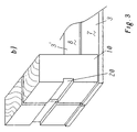
- Figure 3 shows another example of a possibility of fixing the spacers 10 of adjacent part pallets 7/8. It is a perspective view and the load bearing surface construction has been removed for displaying the essential elements of this embodiment.
- the spacers are provided with recesses on their outside face and on the edge opposite to the side facing the adjacent part pallet.
- the wooden panel 6 more or less aligns with the side surface of the spacer which lies opposite to the side surface of the spacer which is facing the neighbouring part pallet.
- such a slot 20 should have a width e in the range of 3 to 10 mm and a depth d in the range of between 6 and 16 mm. Deeper slots are usually not advantageous since they reduce the overall stability of the attachment of the board to the spacer and thus of the attachment of the two part pallets to each other.
- the slot 20 is formed by a horizontal groove located on the lateral side surface of the spacer exterior to the pallet.
- the groove has a height f which is in the range of 3mm to 40 mm.
- the height has to be large enough to allow the introduction of the corresponding tool, for example is screwdriver, but small enough not to give rise to too large a reduction in stability of the connection between the connecting board 6 and the spacers 10.
- This groove extends preferentially over the full width of each of the spacers, and the production of such grooves is particularly easy, if the grooves on both spacers 10 are located at the same height. Of course, it is also possible to provide such a groove only on one of the spacers 10.
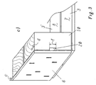
- Figure 3c shows the same embodiment as in figure 3b), wherein in this case the connecting board 6 is shown as well. It can now be seen that the groove in combination with the connecting board 6 forms a slot 20, with a depth extending over the full width of the two spacers 10. This is not only an embodiment which is particularly easy and cheap to produce, but it also allows to introduce for example a screwdriver very deeply into that slot and correspondingly allows a particularly efficient leverage to take off the connecting board 6.
Landscapes
- Engineering & Computer Science (AREA)
- Mechanical Engineering (AREA)
- Pallets (AREA)
Claims (18)
- Palette (1) mit einer Trageplattform (4,5), aufgebaut auf einer ganzen Zahl von Teilpaletten (7,8), welche in angrenzender Weise nebeneinander angeordnet sind, wobei jede Teilpalette (7,8) eine Trageplattform aufweist mit Beabstandungselementen (9,10), welche die Trageplattform (4,5) tragen, wobei Mittel (6) vorgesehen sind zur Verbindung von benachbarten Beabstandungselementen (10, 10') von benachbarten Teilpaletten (7,8) an deren lateraler Seitenfläche, welche der Aussenseite der Palette (1) zugewandt ist, und wobei diese Mittel entfernbar mit den benachbarten Beabstandungselementen (10, 10') verbunden sind,
dadurch gekennzeichnet, dass
die Mittel (6) in Form einer Tafel, eines Brettes, einer Platte oder Scheibe oder einer Kombination davon vorgesehen sind, und dass die Mittel (6) mit den Beabstandungselementen (9,10) unter Zuhilfenahme von Klammern (12), Schrauben, Nägeln, Stiften, Dornen, Bolzen oder Kombinationen davon befestigt sind. - Palette (1) nach Anspruch 1, dadurch gekennzeichnet, dass sie aus zwei symmetrischen Halb-Paletten (7,8) aufgebaut ist, wobei die Trennlinie zwischen den beiden Halbpaletten (7,8) vorzugsweise senkrecht zur langen Seite der Palette (1) liegt, und wobei Mittel (6) auf beiden Seiten der Palette (1) vorgesehen sind.
- Palette (1) nach einem der vorhergehenden Ansprüche, dadurch gekennzeichnet, dass die Mittel (6) aus Holz, Metall oder Plastik oder einer Kombination davon gefertigt sind, und wobei vorzugsweise ein Laminat aus Holz oder Plastik verwendet wird.
- Palette (1) nach einem der vorhergehenden Ansprüche, dadurch gekennzeichnet, dass die Mittel (6) in Form einer bevorzugtermassen laminierten Platte aus Holz (6) mit einer Dicke (c) im Bereich von 5-15 mm, vorzugsweise von 9-12 mm, vorgesehen sind, wobei vorzugsweise die hölzerne Platte (6) eine Breite (a) im Bereich von 80-150 mm, vorzugsweise von 90-120 mm, und eine Höhe (b) im Bereich von 80-150 mm, vorzugsweise von 100-130 mm aufweist.
- Palette (1) nach einem der vorhergehenden Ansprüche, dadurch gekennzeichnet, dass die Schenkel der Klammern (12) eine Länge im Bereich von 15-45 mm aufweisen und aus Stahl gefertigt sind.
- Palette (1) nach einem der vorhergehenden Ansprüche, dadurch gekennzeichnet, dass die Mittel (6) oder die Beabstandungselemente (9,10) mit Hilfsmitteln (13,15,16, 17,18) versehen sind für die Entfernung der Mittel (6) von den Beabstandungselementen (10,10'), wobei diese Hilfsmittel zugänglich sind von der Aussenseite der Palette (1), auch wenn die Palette mit einer Last beladen ist.
- Palette (1) nach Anspruch 6, dadurch gekennzeichnet, dass die Hilfsmittel (13,15,16,17,18) gegeben sind in Form von wenigstens einer Aussparung, Loch (13), Schlitz (15, 20), Platte (16), U-Bolzen (17) oder einer Kombination davon.
- Palette (1) nach Anspruch 7, dadurch gekennzeichnet, dass im Fall eines Lochs (13) dieses Loch eine Breite im Bereich von 15-50 mm, vorzugsweise im Bereich von 30-40 mm, und eine Höhe im Bereich von 10-30 mm, vorzugsweise im Bereich von 15-25 mm, aufweist.
- Palette (1) nach Anspruch 7, dadurch gekennzeichnet, dass die Hilfsmittel in Form wenigstens eines Schlitzes (20) vorgesehen sind, welche durch Aussparungen auf der lateralen Seitenoberfläche zur Aussenseite der Palette der Beabstandungselemente (9,10) an der Kante auf der gegenüberliegenden Seite zur Seite des Beabstandungselementes, welches der benachbarten Teil-Palette zugerichtet ist, wobei die Mittel (6) eine Breite (a) aufweisen, so dass sie im Wesentlichen die Aussparung bedecken, was zur Bildung des genannten Schlitzes (20) führt.
- Palette (1) nach Anspruch 9, dadurch gekennzeichnet, dass der Schlitz (20) eine Breite (e) im Bereich von 3-10 mm und eine Tiefe (d) im Bereich von 6-16 mm aufweist, wobei vorzugsweise der Schlitz (20) sich im Wesentlichen über die volle Höhe des Beabstandungselementes (9,10) erstreckt.
- Palette (1) nach Anspruch 7, dadurch gekennzeichnet, dass die Hilfsmittel in Form wenigstens eines Schlitzes (20) gebildet durch Nuten angeordnet an der lateralen seitlichen Oberfläche zur Aussenseite der Palette gewandt der Beabstandungselemente (9,10), wobei die Mittel (6) eine Breite (a) aufweisen, so dass die Nuten im Wesentlichen bedeckt werden, was zur Bildung der genannten Schlitze (20) führt.
- Palette (1) nach Anspruch 11, dadurch gekennzeichnet, dass der Schlitz (20) eine Breite (e) im Bereich von 3-10 mm, eine Höhe (f) im Bereich von 3-40 mm, und eine Tiefe, welche sich über die volle Breite der Beabstandungselemente erstreckt, aufweist.
- Verfahren zur Herstellung einer Doppelpalette (1), deren individuelle Teile (7, 8) voneinander gelöst werden können unter Zuhilfenahme der Entfernung von Mitteln (6), welche benachbarte Beabstandungselemente (10, 10') von benachbarten Teil-Paletten (7, 8), an deren lateraler Seitenfläche zur Aussenseite der Palette (1) zugewandt verbunden sind, wobei zwei Teilpaletten (7, 8) nebeneinander angeordnet werden und anschliessend benachbarte Beabstandungselemente (10, 10') von benachbarten Teil-Paletten (7, 8) miteinander verbunden werden unter Zuhilfenahme von Bolzen, Klammern oder Nägeln, wobei die Mittel (6) an die laterale Seitenfläche zur Aussenseite der Palette zugewandt befestigt werden, wobei die Mittel (6) in Form einer Tafel, eines Brettes, einer Platte oder einer Scheibe vorgesehen sind, oder einer Kombination davon, und wobei vorzugsweise solche Mittel (6) auf beiden Seite der Doppelpalette (1) vorgesehen sind.
- Verfahren nach Anspruch 13, dadurch gekennzeichnet, dass die Mittel (6) in Form einer vorzugsweise laminierten hölzernen Platte (6) einer Dicke (c) im Bereich von 5-15 mm, vorzugsweise von 6-12 mm, vorgesehen sind, wobei vorzugsweise die hölzerne Platte eine Breite (a) im Bereich von 80-150 mm, vorzugsweise von 90-120 mm, aufweist und eine Höhe (b) im Bereich von 80-150 mm, vorzugsweise im Bereich von 100-130 mm.
- Verfahren nach einem der Ansprüche 13 oder 14, dadurch gekennzeichnet, dass zwischen 4 und 10, vorzugsweise zwischen 5 und 7, Klammern (12), Bolzen oder Nägel vorgesehen sind zur Fixierung der Mittel (6) an den Beabstandungselementen (10 , 10').
- Verfahren nach einem der Ansprüche 13 bis 15, dadurch gekennzeichnet, dass die Mittel (6) oder die Beabstandungselmente (9,10) mit Hilfsmitteln (13,15,16,17,18,20) versehen sind, um die Mittel (6) von den Beabstandungselementen (10, 10') zu entfernen, wobei diese Hilfsmittel von der Aussenseite der Palette (1) zugänglich sind, selbst wenn die Palette mit einer Last beladen ist, und wobei vorzugsweise die Hilfsmittel in Form wenigstens einer Aussparung, eines Loches (13), eines Schlitzes (15,20), einer Platte (16) eines U-Bolzens (17) oder einer Kombination davon vorgesehen sind.
- Verfahren nach Anspruch 16, dadurch gekennzeichnet, dass Beabstandungselemente (9, 10) verwendet werden, welche an den äusseren Positionen, welche den benachbarten Teilpaletten zugewandt sind, mit Aussparungen oder Nuten nach einem der Ansprüche 9, 10, 11 oder 12, versehen sind, oder dass vor der Fixierung der Mittel in Form einer hölzernen Platte oder eines Brettes (6) an den Beabstandungselementen (9, 10) Aussparungen oder Nuten nach einem der Ansprüche 9, 10, 11 oder 12 aus den Beabstandungselementen (9, 10) herausgefräst werden an den äusseren Kanten der Beabstandungselemente oder an deren lateraler Seitenfläche, welche der Aussenseite der Palette zugewandt ist.
- Verfahren nach einem der Ansprüche 13 bis 18, zur Herstellung einer Doppelpalette nach einem der Ansprüche 1 bis 12.
Priority Applications (5)
| Application Number | Priority Date | Filing Date | Title |
|---|---|---|---|
| EP03004695A EP1435328B2 (de) | 2003-03-04 | 2003-03-04 | Zusammensetzung aus lösbaren Teilpaletten |
| DE60301120T DE60301120T3 (de) | 2003-03-04 | 2003-03-04 | Zusammensetzung aus lösbaren Teilpaletten |
| AT03004695T ATE300478T1 (de) | 2003-03-04 | 2003-03-04 | Zusammensetzung aus lösbaren teilpaletten |
| AU2003294963A AU2003294963A1 (en) | 2003-03-04 | 2003-12-29 | Pallet assembly formed of separable part pallets |
| PCT/EP2003/014929 WO2004060758A1 (en) | 2003-03-04 | 2003-12-29 | Pallet assembly formed of separable part pallets |
Applications Claiming Priority (1)
| Application Number | Priority Date | Filing Date | Title |
|---|---|---|---|
| EP03004695A EP1435328B2 (de) | 2003-03-04 | 2003-03-04 | Zusammensetzung aus lösbaren Teilpaletten |
Publications (3)
| Publication Number | Publication Date |
|---|---|
| EP1435328A1 EP1435328A1 (de) | 2004-07-07 |
| EP1435328B1 true EP1435328B1 (de) | 2005-07-27 |
| EP1435328B2 EP1435328B2 (de) | 2011-06-15 |
Family
ID=32479926
Family Applications (1)
| Application Number | Title | Priority Date | Filing Date |
|---|---|---|---|
| EP03004695A Expired - Lifetime EP1435328B2 (de) | 2003-03-04 | 2003-03-04 | Zusammensetzung aus lösbaren Teilpaletten |
Country Status (5)
| Country | Link |
|---|---|
| EP (1) | EP1435328B2 (de) |
| AT (1) | ATE300478T1 (de) |
| AU (1) | AU2003294963A1 (de) |
| DE (1) | DE60301120T3 (de) |
| WO (1) | WO2004060758A1 (de) |
Family Cites Families (5)
| Publication number | Priority date | Publication date | Assignee | Title |
|---|---|---|---|---|
| FR2157171A5 (de) * | 1971-10-13 | 1973-06-01 | Bourreau Alain | |
| FR2585671B2 (fr) * | 1984-08-08 | 1990-11-09 | Socar | Palette de manutention divisible en deux palettes elementaires |
| FR2568856B1 (fr) * | 1984-08-08 | 1990-05-11 | Socar | Palette de manutention divisible en deux palettes elementaires |
| US4694962A (en) | 1985-06-10 | 1987-09-22 | Taub Ronald H | Standard dimension pallet assembly formed of separate abutted segments |
| AU7957098A (en) * | 1998-06-08 | 1999-12-30 | Hendry Mechanical Works | Load shipping systems |
-
2003
- 2003-03-04 AT AT03004695T patent/ATE300478T1/de active
- 2003-03-04 EP EP03004695A patent/EP1435328B2/de not_active Expired - Lifetime
- 2003-03-04 DE DE60301120T patent/DE60301120T3/de not_active Expired - Lifetime
- 2003-12-29 AU AU2003294963A patent/AU2003294963A1/en not_active Abandoned
- 2003-12-29 WO PCT/EP2003/014929 patent/WO2004060758A1/en not_active Application Discontinuation
Also Published As
| Publication number | Publication date |
|---|---|
| DE60301120T3 (de) | 2012-03-15 |
| DE60301120T2 (de) | 2006-12-28 |
| ATE300478T1 (de) | 2005-08-15 |
| EP1435328A1 (de) | 2004-07-07 |
| AU2003294963A1 (en) | 2004-07-29 |
| WO2004060758A1 (en) | 2004-07-22 |
| EP1435328B2 (de) | 2011-06-15 |
| DE60301120D1 (de) | 2005-09-01 |
Similar Documents
| Publication | Publication Date | Title |
|---|---|---|
| US6019226A (en) | Demountable palletized container | |
| KR20070001059A (ko) | 절첩식 통합 팰럿 시스템 | |
| US6619477B2 (en) | Pallet and transportation container | |
| US6079337A (en) | Supporting structure | |
| CN113518748B (zh) | 混成托板 | |
| US9359109B1 (en) | Pallet support block and a pallet constructed with pallet support blocks | |
| EP1435328B1 (de) | Zusammensetzung aus lösbaren Teilpaletten | |
| US5701827A (en) | Pallet assembly | |
| AU2008101327A4 (en) | Pallet system | |
| US20100229765A1 (en) | Industrial pallets formed of recycled and/or scrap lumber and method of manufacturing | |
| US5813555A (en) | Wing-end cleated crate | |
| KR200214418Y1 (ko) | 컨테이너용 포장 운반상자 | |
| KR200242507Y1 (ko) | 유리전용 파렛트 | |
| JP3832085B2 (ja) | 分解可能木製コンテナ | |
| ZA200503738B (en) | Collapsible container | |
| KR200218569Y1 (ko) | 화물운반용 조립식 목재상자 | |
| JP3109569U (ja) | 金属製パレットの脚柱用補強カバー | |
| KR20180001848A (ko) | 잠금키를 구비한 조립식 파렛트 및 이의 제조방법 | |
| JP2003175938A (ja) | 荷受け用足材 | |
| KR20190000866A (ko) | 잠금키를 구비한 조립식 파렛트 | |
| EP3677524A1 (de) | Palettenmodul, sortiment von palettenmodulen, und daraus aufgebauter palettenverbund | |
| JPS5845228Y2 (ja) | 段ボ−ルパレツト | |
| KR20230134861A (ko) | 조립식 파레트 | |
| KR100464733B1 (ko) | 물건적재용 파렛트 및 그 조립방법 | |
| JP2002302120A (ja) | 輸送用パレット |
Legal Events
| Date | Code | Title | Description |
|---|---|---|---|
| PUAI | Public reference made under article 153(3) epc to a published international application that has entered the european phase |
Free format text: ORIGINAL CODE: 0009012 |
|
| AK | Designated contracting states |
Kind code of ref document: A1 Designated state(s): AT BE BG CH CY CZ DE DK EE ES FI FR GB GR HU IE IT LI LU MC NL PT SE SI SK TR |
|
| AX | Request for extension of the european patent |
Extension state: AL LT LV MK RO |
|
| EL | Fr: translation of claims filed | ||
| 17P | Request for examination filed |
Effective date: 20040721 |
|
| 17Q | First examination report despatched |
Effective date: 20040921 |
|
| GRAP | Despatch of communication of intention to grant a patent |
Free format text: ORIGINAL CODE: EPIDOSNIGR1 |
|
| AKX | Designation fees paid |
Designated state(s): AT BE BG CH CY CZ DE DK EE ES FI FR GB GR HU IE IT LI LU MC NL PT SE SI SK TR |
|
| GRAS | Grant fee paid |
Free format text: ORIGINAL CODE: EPIDOSNIGR3 |
|
| GRAA | (expected) grant |
Free format text: ORIGINAL CODE: 0009210 |
|
| AK | Designated contracting states |
Kind code of ref document: B1 Designated state(s): AT BE BG CH CY CZ DE DK EE ES FI FR GB GR HU IE IT LI LU MC NL PT SE SI SK TR |
|
| PG25 | Lapsed in a contracting state [announced via postgrant information from national office to epo] |
Ref country code: TR Free format text: LAPSE BECAUSE OF FAILURE TO SUBMIT A TRANSLATION OF THE DESCRIPTION OR TO PAY THE FEE WITHIN THE PRESCRIBED TIME-LIMIT Effective date: 20050727 Ref country code: IT Free format text: LAPSE BECAUSE OF FAILURE TO SUBMIT A TRANSLATION OF THE DESCRIPTION OR TO PAY THE FEE WITHIN THE PRESCRIBED TIME-LIMIT;WARNING: LAPSES OF ITALIAN PATENTS WITH EFFECTIVE DATE BEFORE 2007 MAY HAVE OCCURRED AT ANY TIME BEFORE 2007. THE CORRECT EFFECTIVE DATE MAY BE DIFFERENT FROM THE ONE RECORDED. Effective date: 20050727 Ref country code: EE Free format text: LAPSE BECAUSE OF FAILURE TO SUBMIT A TRANSLATION OF THE DESCRIPTION OR TO PAY THE FEE WITHIN THE PRESCRIBED TIME-LIMIT Effective date: 20050727 Ref country code: CH Free format text: LAPSE BECAUSE OF FAILURE TO SUBMIT A TRANSLATION OF THE DESCRIPTION OR TO PAY THE FEE WITHIN THE PRESCRIBED TIME-LIMIT Effective date: 20050727 Ref country code: NL Free format text: LAPSE BECAUSE OF FAILURE TO SUBMIT A TRANSLATION OF THE DESCRIPTION OR TO PAY THE FEE WITHIN THE PRESCRIBED TIME-LIMIT Effective date: 20050727 Ref country code: FI Free format text: LAPSE BECAUSE OF FAILURE TO SUBMIT A TRANSLATION OF THE DESCRIPTION OR TO PAY THE FEE WITHIN THE PRESCRIBED TIME-LIMIT Effective date: 20050727 Ref country code: SI Free format text: LAPSE BECAUSE OF FAILURE TO SUBMIT A TRANSLATION OF THE DESCRIPTION OR TO PAY THE FEE WITHIN THE PRESCRIBED TIME-LIMIT Effective date: 20050727 Ref country code: BE Free format text: LAPSE BECAUSE OF FAILURE TO SUBMIT A TRANSLATION OF THE DESCRIPTION OR TO PAY THE FEE WITHIN THE PRESCRIBED TIME-LIMIT Effective date: 20050727 Ref country code: SK Free format text: LAPSE BECAUSE OF FAILURE TO SUBMIT A TRANSLATION OF THE DESCRIPTION OR TO PAY THE FEE WITHIN THE PRESCRIBED TIME-LIMIT Effective date: 20050727 Ref country code: LI Free format text: LAPSE BECAUSE OF FAILURE TO SUBMIT A TRANSLATION OF THE DESCRIPTION OR TO PAY THE FEE WITHIN THE PRESCRIBED TIME-LIMIT Effective date: 20050727 Ref country code: CZ Free format text: LAPSE BECAUSE OF FAILURE TO SUBMIT A TRANSLATION OF THE DESCRIPTION OR TO PAY THE FEE WITHIN THE PRESCRIBED TIME-LIMIT Effective date: 20050727 |
|
| REG | Reference to a national code |
Ref country code: GB Ref legal event code: FG4D |
|
| REG | Reference to a national code |
Ref country code: CH Ref legal event code: EP |
|
| REG | Reference to a national code |
Ref country code: IE Ref legal event code: FG4D |
|
| REF | Corresponds to: |
Ref document number: 60301120 Country of ref document: DE Date of ref document: 20050901 Kind code of ref document: P |
|
| PG25 | Lapsed in a contracting state [announced via postgrant information from national office to epo] |
Ref country code: GR Free format text: LAPSE BECAUSE OF FAILURE TO SUBMIT A TRANSLATION OF THE DESCRIPTION OR TO PAY THE FEE WITHIN THE PRESCRIBED TIME-LIMIT Effective date: 20051027 Ref country code: BG Free format text: LAPSE BECAUSE OF FAILURE TO SUBMIT A TRANSLATION OF THE DESCRIPTION OR TO PAY THE FEE WITHIN THE PRESCRIBED TIME-LIMIT Effective date: 20051027 Ref country code: SE Free format text: LAPSE BECAUSE OF FAILURE TO SUBMIT A TRANSLATION OF THE DESCRIPTION OR TO PAY THE FEE WITHIN THE PRESCRIBED TIME-LIMIT Effective date: 20051027 Ref country code: DK Free format text: LAPSE BECAUSE OF FAILURE TO SUBMIT A TRANSLATION OF THE DESCRIPTION OR TO PAY THE FEE WITHIN THE PRESCRIBED TIME-LIMIT Effective date: 20051027 |
|
| PG25 | Lapsed in a contracting state [announced via postgrant information from national office to epo] |
Ref country code: ES Free format text: LAPSE BECAUSE OF FAILURE TO SUBMIT A TRANSLATION OF THE DESCRIPTION OR TO PAY THE FEE WITHIN THE PRESCRIBED TIME-LIMIT Effective date: 20051107 |
|
| PG25 | Lapsed in a contracting state [announced via postgrant information from national office to epo] |
Ref country code: PT Free format text: LAPSE BECAUSE OF FAILURE TO SUBMIT A TRANSLATION OF THE DESCRIPTION OR TO PAY THE FEE WITHIN THE PRESCRIBED TIME-LIMIT Effective date: 20051227 |
|
| PG25 | Lapsed in a contracting state [announced via postgrant information from national office to epo] |
Ref country code: HU Free format text: LAPSE BECAUSE OF FAILURE TO SUBMIT A TRANSLATION OF THE DESCRIPTION OR TO PAY THE FEE WITHIN THE PRESCRIBED TIME-LIMIT Effective date: 20060128 |
|
| REG | Reference to a national code |
Ref country code: CH Ref legal event code: PL |
|
| NLV1 | Nl: lapsed or annulled due to failure to fulfill the requirements of art. 29p and 29m of the patents act | ||
| PG25 | Lapsed in a contracting state [announced via postgrant information from national office to epo] |
Ref country code: IE Free format text: LAPSE BECAUSE OF NON-PAYMENT OF DUE FEES Effective date: 20060306 |
|
| PG25 | Lapsed in a contracting state [announced via postgrant information from national office to epo] |
Ref country code: MC Free format text: LAPSE BECAUSE OF NON-PAYMENT OF DUE FEES Effective date: 20060331 Ref country code: LU Free format text: LAPSE BECAUSE OF NON-PAYMENT OF DUE FEES Effective date: 20060331 |
|
| ET | Fr: translation filed | ||
| PLBI | Opposition filed |
Free format text: ORIGINAL CODE: 0009260 |
|
| PLAX | Notice of opposition and request to file observation + time limit sent |
Free format text: ORIGINAL CODE: EPIDOSNOBS2 |
|
| 26 | Opposition filed |
Opponent name: CONDAT IMMEUBLE LE LA FAYETTE Effective date: 20060421 |
|
| PLAF | Information modified related to communication of a notice of opposition and request to file observations + time limit |
Free format text: ORIGINAL CODE: EPIDOSCOBS2 |
|
| PLBB | Reply of patent proprietor to notice(s) of opposition received |
Free format text: ORIGINAL CODE: EPIDOSNOBS3 |
|
| REG | Reference to a national code |
Ref country code: IE Ref legal event code: MM4A |
|
| GBPC | Gb: european patent ceased through non-payment of renewal fee |
Effective date: 20070304 |
|
| PG25 | Lapsed in a contracting state [announced via postgrant information from national office to epo] |
Ref country code: GB Free format text: LAPSE BECAUSE OF NON-PAYMENT OF DUE FEES Effective date: 20070304 |
|
| PG25 | Lapsed in a contracting state [announced via postgrant information from national office to epo] |
Ref country code: CY Free format text: LAPSE BECAUSE OF FAILURE TO SUBMIT A TRANSLATION OF THE DESCRIPTION OR TO PAY THE FEE WITHIN THE PRESCRIBED TIME-LIMIT Effective date: 20050727 |
|
| PLAY | Examination report in opposition despatched + time limit |
Free format text: ORIGINAL CODE: EPIDOSNORE2 |
|
| PLBC | Reply to examination report in opposition received |
Free format text: ORIGINAL CODE: EPIDOSNORE3 |
|
| PLAL | Information related to reply to examination report in opposition modified |
Free format text: ORIGINAL CODE: EPIDOSCORE3 |
|
| PLAY | Examination report in opposition despatched + time limit |
Free format text: ORIGINAL CODE: EPIDOSNORE2 |
|
| PLAH | Information related to despatch of examination report in opposition + time limit modified |
Free format text: ORIGINAL CODE: EPIDOSCORE2 |
|
| PLBC | Reply to examination report in opposition received |
Free format text: ORIGINAL CODE: EPIDOSNORE3 |
|
| PLAY | Examination report in opposition despatched + time limit |
Free format text: ORIGINAL CODE: EPIDOSNORE2 |
|
| PLBC | Reply to examination report in opposition received |
Free format text: ORIGINAL CODE: EPIDOSNORE3 |
|
| PUAH | Patent maintained in amended form |
Free format text: ORIGINAL CODE: 0009272 |
|
| STAA | Information on the status of an ep patent application or granted ep patent |
Free format text: STATUS: PATENT MAINTAINED AS AMENDED |
|
| PGFP | Annual fee paid to national office [announced via postgrant information from national office to epo] |
Ref country code: FR Payment date: 20110404 Year of fee payment: 9 Ref country code: AT Payment date: 20110314 Year of fee payment: 9 |
|
| 27A | Patent maintained in amended form |
Effective date: 20110615 |
|
| AK | Designated contracting states |
Kind code of ref document: B2 Designated state(s): AT BE BG CH CY CZ DE DK EE ES FI FR GB GR HU IE IT LI LU MC NL PT SE SI SK TR |
|
| REG | Reference to a national code |
Ref country code: DE Ref legal event code: R102 Ref document number: 60301120 Country of ref document: DE Effective date: 20110615 |
|
| PGFP | Annual fee paid to national office [announced via postgrant information from national office to epo] |
Ref country code: DE Payment date: 20110325 Year of fee payment: 9 |
|
| REG | Reference to a national code |
Ref country code: AT Ref legal event code: MM01 Ref document number: 300478 Country of ref document: AT Kind code of ref document: T Effective date: 20120304 |
|
| REG | Reference to a national code |
Ref country code: FR Ref legal event code: ST Effective date: 20121130 |
|
| PG25 | Lapsed in a contracting state [announced via postgrant information from national office to epo] |
Ref country code: AT Free format text: LAPSE BECAUSE OF NON-PAYMENT OF DUE FEES Effective date: 20120304 Ref country code: FR Free format text: LAPSE BECAUSE OF NON-PAYMENT OF DUE FEES Effective date: 20120402 |
|
| REG | Reference to a national code |
Ref country code: DE Ref legal event code: R119 Ref document number: 60301120 Country of ref document: DE Effective date: 20121002 |
|
| PG25 | Lapsed in a contracting state [announced via postgrant information from national office to epo] |
Ref country code: DE Free format text: LAPSE BECAUSE OF FAILURE TO SUBMIT A TRANSLATION OF THE DESCRIPTION OR TO PAY THE FEE WITHIN THE PRESCRIBED TIME-LIMIT Effective date: 20121002 |