EP1435312B1 - Vorrichtung zur Stromversorgung eines elektrischen Verbrauchers in einem Kraftfahrzeug - Google Patents
Vorrichtung zur Stromversorgung eines elektrischen Verbrauchers in einem Kraftfahrzeug Download PDFInfo
- Publication number
- EP1435312B1 EP1435312B1 EP20020293277 EP02293277A EP1435312B1 EP 1435312 B1 EP1435312 B1 EP 1435312B1 EP 20020293277 EP20020293277 EP 20020293277 EP 02293277 A EP02293277 A EP 02293277A EP 1435312 B1 EP1435312 B1 EP 1435312B1
- Authority
- EP
- European Patent Office
- Prior art keywords
- rotatable
- metallic
- steering wheel
- connector
- steering column
- Prior art date
- Legal status (The legal status is an assumption and is not a legal conclusion. Google has not performed a legal analysis and makes no representation as to the accuracy of the status listed.)
- Expired - Lifetime
Links
- 230000008054 signal transmission Effects 0.000 claims 1
- 239000002184 metal Substances 0.000 description 19
- 239000004020 conductor Substances 0.000 description 5
- 230000005540 biological transmission Effects 0.000 description 3
- 238000010438 heat treatment Methods 0.000 description 3
- 230000004323 axial length Effects 0.000 description 1
- 230000005611 electricity Effects 0.000 description 1
- 238000009434 installation Methods 0.000 description 1
- 238000002955 isolation Methods 0.000 description 1
- 238000005096 rolling process Methods 0.000 description 1
- 238000004804 winding Methods 0.000 description 1
Images

Classifications
-
- B—PERFORMING OPERATIONS; TRANSPORTING
- B60—VEHICLES IN GENERAL
- B60R—VEHICLES, VEHICLE FITTINGS, OR VEHICLE PARTS, NOT OTHERWISE PROVIDED FOR
- B60R16/00—Electric or fluid circuits specially adapted for vehicles and not otherwise provided for; Arrangement of elements of electric or fluid circuits specially adapted for vehicles and not otherwise provided for
- B60R16/02—Electric or fluid circuits specially adapted for vehicles and not otherwise provided for; Arrangement of elements of electric or fluid circuits specially adapted for vehicles and not otherwise provided for electric constitutive elements
- B60R16/023—Electric or fluid circuits specially adapted for vehicles and not otherwise provided for; Arrangement of elements of electric or fluid circuits specially adapted for vehicles and not otherwise provided for electric constitutive elements for transmission of signals between vehicle parts or subsystems
- B60R16/027—Electric or fluid circuits specially adapted for vehicles and not otherwise provided for; Arrangement of elements of electric or fluid circuits specially adapted for vehicles and not otherwise provided for electric constitutive elements for transmission of signals between vehicle parts or subsystems between relatively movable parts of the vehicle, e.g. between steering wheel and column
Definitions
- the invention relates to a device for powering an electrical Consumer in a motor vehicle, which is rotatably attached to a steering column Steering wheel has, in which the consumer with a voltage source of Motor vehicle is located in a circuit and connected to the steering wheel of the same and in which in the circuit with a fixed part of the steering column On the one hand and the steering wheel on the other hand connected connector is turned on, the as a rotary body with at least one pair of mutually associated metallic Is formed components, one of which is rotatable about a common axis and mounted between those on both components fitting, rotatable metal body are, and in which one of the components with the fixed part of the steering column and the other component is connected to the steering wheel (US 4,462,648 A).
- Such a device is for example for the transmission of electricity to Triggering an impact protection used in motor vehicles, in which in the steering wheel Airbag, a so-called "airbag” is attached. But you can also, for example for a sliding door cabling or a steering gear cabling in motor vehicles be used.
- the device connects the fixed voltage source a motor vehicle with the rotating in two directions steering wheel.
- Airbag cassette used in one with the rotor on the one hand and the stator on the other hand connected, in turns extending electrical line is attached.
- the line can be connected to the rotor of the Airbag cassette, which is mounted on the steering wheel, the rotational movements of the same follow smoothly. It is one of the number to the voltage source to be connected consumer corresponding number of electrical conductors equipped.
- the known device is used for electrical connection between at least two on the steering wheel axle of a Motor vehicle located, rotatable components. These are for example one chassis-fixed bearing part and an electric ignition of one on the steering wheel stored, serving as occupant Prollschutz air docks.
- a Motor vehicle located, rotatable components These are for example one chassis-fixed bearing part and an electric ignition of one on the steering wheel stored, serving as occupant Prollschutz air docks.
- the invention is based on the object, the initially described device so form, that even higher currents can be transmitted without the Number of consumers to be connected to the voltage source of the motor vehicle must be restricted.
- the device another located in the steering column, the signal and / or power transmission rotary connectors (3) has, and that the rotary body in this rotary connector is attached, the one with a fixed part of Steering column connected stator and a rotor connected to the steering wheel between which there is a winding electrical wire is arranged.
- This device is in particular for all consumers of a motor vehicle usable, for whose power supply higher currents are required.
- One Such consumers for example, a steering wheel heating, the more comfortable Passenger car is now standard.
- the increased contact resistance of the Rotary bodies used in this device are increasing because of the increased Amperage not disturbing noticeable.
- the device is equipped with a rotary connector - the described above "airbag cassette" - connected and together with the same built into a steering column of a motor vehicle. That's because of her small footprint possible at any time. It is possible, for example, the Position the rotating body in a central bore of the rotary connector. He is then housed without increased space requirement in the steering column and can additionally as Swivel bearings are used.
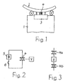
- Fig. 1 The illustration in Fig. 1 is very simplified. It should only have a basic structure play.
- a rotary connector 3-in the following airbag cassette 3 called-and a rotary body 4 are mounted, both connected on the one hand with the steering column 1 and on the other hand with the steering wheel 2 are.
- the airbag cassette 3 is known in principle and, for example, in the above DE 199 60 205 A1 described.
- the rotary body 4 is used in addition to the Airbag cassette 3 as a separate unit for power transmission, in particular to Consumers with increased power consumption.
- the rotary body 4 is in the circuit of a voltage source 5, in which it is for example, is the battery of the motor vehicle. The circuit can through closed a switch 6 and opened again.
- a Connected consumer V which is mechanically connected to the steering wheel 2. at the consumer V in a preferred embodiment is an electrical Heating for the steering wheel 2. It consists for example of the steering wheel. 2 wrapped, insulated heating wires.
- Rotary body 4 consisting of two mutually insulated rotary parts 4a and 4b, between which according to FIG. 3 the load V is connected and which are connected to different poles of the voltage source 5.
- the rotary body 4 can basically as per se known ball bearings or bearings be executed. His metallic components are then two concentric metal rings, between which rotatable metal body are mounted, so balls or rollers or Needles.
- the rotary body 4 can also be constructed differently, with a fixed and a rotatable component, between which rotatable metal body are attached. It must only be ensured that always at least one Metal body touches both components.
- the rotary body 4 is at the Airbag cassette 3 is mounted and mounted together with the same in the steering column 1.
- a rotary body 4 is used, the consists of two mutually insulated rotary parts 4a and 4b, with the Airbag cassette 3 are. They are in the mounting position shown in FIG. 3 with each a pole of the voltage source 5 is connected. The rotating parts 4a and 4b can thereby without additional space in a central bore 7 of the airbag cassette 3rd be attached, as shown in Fig. 4.
- the airbag cassette 3 has a with the steering column 1 connected stator 8 and connected to the steering wheel 2 rotor 9, which is rotatable relative to the stator 8 about a common axis A. Stator 8 and rotor 9 enclose an annular space 10 between them in which one turns extending, can not be arranged with illustrated electrical line.
- Each rotary part 4a and 4b has two concentric metal rings 11th and 12, between which self-rotating metal body, such as rollers 13, are arranged.
- the metal rings 11 are connected to the rotor 9 of the airbag cassette 3 and the Metal rings 12 connected to the stator 8.
- the metal rings 12 for example, connected to the voltage source 5, while the consumer V to the metal rings 11 is connected.
- the circuit is driven by the rollers 13 closed.
- the consumer V is characterized in closed circuit in each Position of the steering wheel 2 powered.
- the rotary body 4 can be constructed in another embodiment also according to FIG be.
- Metal ring 11 of the embodiment of FIG. 4 is here at least one of each good conductive metal existing cylindrical bolt 14 within the metal ring 12th mounted in the direction of the axis of the metal ring 12 and the airbag cassette 3rd extends. The bolts 14 are attached to the rotor 9 of the airbag cassette 3.
- the bolts 14 can be made massive according to the drawings be. But they can also be designed as pipe sections. Since the rotary parts 4a and 4b For mutual isolation in the axial direction are separated from each other, they have different distances from the rotor 9 of the airbag cassette 3.
- the bolts 14 have Accordingly, according to FIG. 5 above on the one hand and below, on the other hand, different axial lengths.
- Per rotary part 4a and 4b is at least one bolt 14 with sleeve 15th intended. But it can also be two or more, in the circumferential direction staggered pin 14 with sleeves 15 on the rotor 9 of the airbag cassette. 3 to be appropriate.
Landscapes
- Engineering & Computer Science (AREA)
- Mechanical Engineering (AREA)
- Air Bags (AREA)
- Steering Controls (AREA)
Description
Claims (7)
- Vorrichtung zur Stromversorgung eines elektrischen Verbrauchers (V) in einem Kraftfahrzeug, das ein an einer Lenksäule (1) drehbar angebrachtes Lenkrad (2) hat, bei welcher der Verbraucher (V) mit einer Spannungsquelle (5) des Kraftfahrzeugs in einem Stromkreis liegt und mit dem Lenkrad (2) desselben verbunden ist und bei welcher in den Stromkreis ein mit einem feststehenden Teil der Lenksäule (1) einerseits und dem Lenkrad (2) andererseits verbundener Verbinder eingeschaltet ist, der als Drehkörper (4) mit mindestens einem Paar von einander zugeordneten metallischen Bauteilen (11,12) ausgebildet ist, von denen eines um eine gemeinsame Achse drehbar ist und zwischen denen an beiden Bauteilen (11,12) anliegende, drehbare Metallkörper (13) angebracht sind, und bei dem eines der Bauteile mit dem feststehenden Teil der Lenksäule (1) und das andere Bauteil mit dem Lenkrad (2) verbunden ist, dadurch gekennzeichnet, daß die Vorrichtung einen weiteren in der Lenksäule (1) befindlichen, der Signal- und/oder Stromübertragung dienenden Drehverbinder (3) aufweist, und daß der Drehkörper (4) in diesem Drehverbinder (3) angebracht ist, der einen mit einem feststehenden Teil der Lenksäule (1) verbundenen Stator (8) und einen mit dem Lenkrad (2) verbundenen Rotor (9) aufweist, zwischen denen eine in Windungen verlaufende elektrische Leitung angeordnet ist.
- Vorrichtung nach Anspruch 1, dadurch gekennzeichnet, daß der Drehkörper (4) in einer zentralen Bohrung (7) des Drehverbinders (3) angeordnet ist.
- Vorrichtung nach Anspruch 1 oder 2, dadurch gekennzeichnet,daß eines der Bauteile des Drehkörpers (4) ein mit dem Stator (8) des Drehverbinders (3) verbundener Metallring (12) und das andere Bauteil mindestens ein innerhalb des Metaltrings (12) angeordneter und sich parallel zur Achse desselben erstreckender, zylindrischer Bolzen (14) ist, der mit dem Rotor (9) des Drehverbinders (3) verbunden ist, unddaß auf dem Bolzen (14) eine am Metallring (12) anliegende metallische Hülse (15) drehbar gelagert ist.
- Vorrichtung nach einem der Ansprüche 1 bis 3, dadurch gekennzeichnet, daß der Drehkörper (4) aus zwei konzentrisch zueinander angeordneten Metallringen (11,12) besteht, zwischen denen die drehbaren Metallkörper (13) angebracht sind.
- Vorrichtung nach Anspruch 4, dadurch gekennzeichnet, daß die Metallkörper (13) Kugeln sind.
- Vorrichtung nach Anspruch 4, dadurch gekennzeichnet, daß die Metallkörper (13) Rollen bzw. Nadeln sind.
- Vorrichtung nach einem der Ansprüche 1 bis 6. dadurch gekennzeichnet, daß der Drehkörper (4) aus zwei gegeneinander isolierten Drehteilen (4a,4b) aus Paaren metallischer Bauteile besteht, die an unterschiedliche Polaritäten der Spannungsquelle (5) angeschlossen sind.
Priority Applications (2)
| Application Number | Priority Date | Filing Date | Title |
|---|---|---|---|
| EP20020293277 EP1435312B1 (de) | 2002-12-30 | 2002-12-30 | Vorrichtung zur Stromversorgung eines elektrischen Verbrauchers in einem Kraftfahrzeug |
| DE50203295T DE50203295D1 (de) | 2002-12-30 | 2002-12-30 | Vorrichtung zur Stromversorgung eines elektrischen Verbrauchers in einem Kraftfahrzeug |
Applications Claiming Priority (1)
| Application Number | Priority Date | Filing Date | Title |
|---|---|---|---|
| EP20020293277 EP1435312B1 (de) | 2002-12-30 | 2002-12-30 | Vorrichtung zur Stromversorgung eines elektrischen Verbrauchers in einem Kraftfahrzeug |
Publications (2)
| Publication Number | Publication Date |
|---|---|
| EP1435312A1 EP1435312A1 (de) | 2004-07-07 |
| EP1435312B1 true EP1435312B1 (de) | 2005-06-01 |
Family
ID=32479832
Family Applications (1)
| Application Number | Title | Priority Date | Filing Date |
|---|---|---|---|
| EP20020293277 Expired - Lifetime EP1435312B1 (de) | 2002-12-30 | 2002-12-30 | Vorrichtung zur Stromversorgung eines elektrischen Verbrauchers in einem Kraftfahrzeug |
Country Status (2)
| Country | Link |
|---|---|
| EP (1) | EP1435312B1 (de) |
| DE (1) | DE50203295D1 (de) |
Family Cites Families (3)
| Publication number | Priority date | Publication date | Assignee | Title |
|---|---|---|---|---|
| US4462648A (en) * | 1981-03-19 | 1984-07-31 | Repa Feinstanzwerk Gmbh | Apparatus for providing a reliable electrical connection |
| US5429508A (en) * | 1994-01-26 | 1995-07-04 | Methode Electronics, Inc. | Automobile steering column interconnector |
| US5851120A (en) * | 1997-02-27 | 1998-12-22 | Raytheon Company | Rotary conduit/ball connector |
-
2002
- 2002-12-30 EP EP20020293277 patent/EP1435312B1/de not_active Expired - Lifetime
- 2002-12-30 DE DE50203295T patent/DE50203295D1/de not_active Expired - Lifetime
Also Published As
| Publication number | Publication date |
|---|---|
| DE50203295D1 (de) | 2005-07-07 |
| EP1435312A1 (de) | 2004-07-07 |
Similar Documents
| Publication | Publication Date | Title |
|---|---|---|
| DE3641706C2 (de) | ||
| DE102006019834B4 (de) | Drehverbindungseinrichtung | |
| DE102010041323A1 (de) | Ladeeinrichtung für ein Elektrofahrzeug nebst Verfahren | |
| DE69516224T2 (de) | Gerät zur elektrischen Verbindung zwischen einem drehenden Kontakt und einer stationären Stromquelle | |
| EP0494446B1 (de) | Elektrisch isoliertes Wälzlager | |
| DE3732124A1 (de) | Vorrichtung zur stromuebertragung zwischen zwei relativ zueinander bewegbaren kontaktstellen | |
| EP2151908A1 (de) | Dynamoelektrische Maschine mit einem mehrteiligen Steckergehäuse | |
| DE102018101365A1 (de) | Gelenkige flache modulare elektrische leistungsschiene für ein fahrzeug | |
| DE202017104597U1 (de) | Restlast-Trennschalter | |
| DE60015444T2 (de) | Drehverbinder | |
| EP1591320A1 (de) | Bordnetz und Schalter für ein Bordnetz | |
| EP0706914B1 (de) | Vorrichtung zur Signalübertragung zwischen zwei Endstellen | |
| DE69822537T2 (de) | Drehmoment und Drehzahl Sensor mit einem einzigen Schleifring | |
| EP0735632A2 (de) | Vorrichtung zur Signalübertragung zwischen zwei Endstellen | |
| DE19525686C2 (de) | Vorrichtung zur Signalübertragung zwischen zwei Endstellen | |
| EP0623442B1 (de) | Verfahren zur Herstellung einer Vorrichtung zur Signalübertragung zwischen zwei Endstellen | |
| EP1435312A1 (de) | Vorrichtung zur Stromversorgung eines elektrischen Verbrauchers in einem Kraftfahrzeug | |
| EP1255330B1 (de) | Vorrichtung zur Stromübertragung zwischen zwei Endstellen | |
| EP0920703B1 (de) | Bewegbare kontaktanordnung für einen niederspannungs-leistungsschalter mit einem schwenklager | |
| EP0536599A2 (de) | Vorrichtung zur Stromübertragung zwischen zwei Endstellen | |
| EP2987682B1 (de) | Anordnung für in einem Kraftfahrzeug montierte elektrische Leitungen | |
| EP0563789B1 (de) | Vorrichtung zur Signalübertragung zwischen zwei relativ zueinander bewegbaren Endstellen | |
| EP3047496B1 (de) | Anschlussstück für einen schalterpol eines schaltgerätes | |
| EP2319140A1 (de) | Elektrische maschine | |
| EP1674344B1 (de) | Anordnung zur Stromversorgung von in einem Kraftfahrzeug angebrachten Stromverbrauchern |
Legal Events
| Date | Code | Title | Description |
|---|---|---|---|
| PUAI | Public reference made under article 153(3) epc to a published international application that has entered the european phase |
Free format text: ORIGINAL CODE: 0009012 |
|
| 17P | Request for examination filed |
Effective date: 20030617 |
|
| AK | Designated contracting states |
Kind code of ref document: A1 Designated state(s): AT BE BG CH CY CZ DE DK EE ES FI FR GB GR IE IT LI LU MC NL PT SE SI SK TR |
|
| AX | Request for extension of the european patent |
Extension state: AL LT LV MK RO |
|
| GRAP | Despatch of communication of intention to grant a patent |
Free format text: ORIGINAL CODE: EPIDOSNIGR1 |
|
| GRAS | Grant fee paid |
Free format text: ORIGINAL CODE: EPIDOSNIGR3 |
|
| AKX | Designation fees paid |
Designated state(s): DE FR IT |
|
| GRAA | (expected) grant |
Free format text: ORIGINAL CODE: 0009210 |
|
| RAX | Requested extension states of the european patent have changed |
Extension state: RO Payment date: 20050207 |
|
| AK | Designated contracting states |
Kind code of ref document: B1 Designated state(s): DE FR IT |
|
| AX | Request for extension of the european patent |
Extension state: RO |
|
| REF | Corresponds to: |
Ref document number: 50203295 Country of ref document: DE Date of ref document: 20050707 Kind code of ref document: P |
|
| ET | Fr: translation filed | ||
| PLBE | No opposition filed within time limit |
Free format text: ORIGINAL CODE: 0009261 |
|
| STAA | Information on the status of an ep patent application or granted ep patent |
Free format text: STATUS: NO OPPOSITION FILED WITHIN TIME LIMIT |
|
| 26N | No opposition filed |
Effective date: 20060302 |
|
| PGFP | Annual fee paid to national office [announced via postgrant information from national office to epo] |
Ref country code: IT Payment date: 20121219 Year of fee payment: 11 |
|
| PGFP | Annual fee paid to national office [announced via postgrant information from national office to epo] |
Ref country code: FR Payment date: 20130130 Year of fee payment: 11 Ref country code: DE Payment date: 20121220 Year of fee payment: 11 |
|
| REG | Reference to a national code |
Ref country code: DE Ref legal event code: R119 Ref document number: 50203295 Country of ref document: DE |
|
| REG | Reference to a national code |
Ref country code: FR Ref legal event code: ST Effective date: 20140829 |
|
| REG | Reference to a national code |
Ref country code: DE Ref legal event code: R119 Ref document number: 50203295 Country of ref document: DE Effective date: 20140701 |
|
| PG25 | Lapsed in a contracting state [announced via postgrant information from national office to epo] |
Ref country code: DE Free format text: LAPSE BECAUSE OF NON-PAYMENT OF DUE FEES Effective date: 20140701 |
|
| PG25 | Lapsed in a contracting state [announced via postgrant information from national office to epo] |
Ref country code: FR Free format text: LAPSE BECAUSE OF NON-PAYMENT OF DUE FEES Effective date: 20131231 |
|
| PG25 | Lapsed in a contracting state [announced via postgrant information from national office to epo] |
Ref country code: IT Free format text: LAPSE BECAUSE OF NON-PAYMENT OF DUE FEES Effective date: 20131231 |
|
| PG25 | Lapsed in a contracting state [announced via postgrant information from national office to epo] |
Ref country code: IT Free format text: LAPSE BECAUSE OF NON-PAYMENT OF DUE FEES Effective date: 20131230 |