EP1435275A1 - Montagesystem - Google Patents

Montagesystem Download PDF

Info

Publication number
EP1435275A1
EP1435275A1 EP03026949A EP03026949A EP1435275A1 EP 1435275 A1 EP1435275 A1 EP 1435275A1 EP 03026949 A EP03026949 A EP 03026949A EP 03026949 A EP03026949 A EP 03026949A EP 1435275 A1 EP1435275 A1 EP 1435275A1
Authority
EP
European Patent Office
Prior art keywords
modules
assembly line
mounting system
assembly
module
Prior art date
Legal status (The legal status is an assumption and is not a legal conclusion. Google has not performed a legal analysis and makes no representation as to the accuracy of the status listed.)
Withdrawn
Application number
EP03026949A
Other languages
English (en)
French (fr)
Inventor
Achim Dittes
Stefan Warmuth
Current Assignee (The listed assignees may be inaccurate. Google has not performed a legal analysis and makes no representation or warranty as to the accuracy of the list.)
BSH Hausgeraete GmbH
Original Assignee
BSH Bosch und Siemens Hausgeraete GmbH
Priority date (The priority date is an assumption and is not a legal conclusion. Google has not performed a legal analysis and makes no representation as to the accuracy of the date listed.)
Filing date
Publication date
Application filed by BSH Bosch und Siemens Hausgeraete GmbH filed Critical BSH Bosch und Siemens Hausgeraete GmbH
Publication of EP1435275A1 publication Critical patent/EP1435275A1/de
Withdrawn legal-status Critical Current

Links

Images

Classifications

    • BPERFORMING OPERATIONS; TRANSPORTING
    • B23MACHINE TOOLS; METAL-WORKING NOT OTHERWISE PROVIDED FOR
    • B23PMETAL-WORKING NOT OTHERWISE PROVIDED FOR; COMBINED OPERATIONS; UNIVERSAL MACHINE TOOLS
    • B23P21/00Machines for assembling a multiplicity of different parts to compose units, with or without preceding or subsequent working of such parts, e.g. with program control
    • B23P21/004Machines for assembling a multiplicity of different parts to compose units, with or without preceding or subsequent working of such parts, e.g. with program control the units passing two or more work-stations whilst being composed
    • BPERFORMING OPERATIONS; TRANSPORTING
    • B65CONVEYING; PACKING; STORING; HANDLING THIN OR FILAMENTARY MATERIAL
    • B65GTRANSPORT OR STORAGE DEVICES, e.g. CONVEYORS FOR LOADING OR TIPPING, SHOP CONVEYOR SYSTEMS OR PNEUMATIC TUBE CONVEYORS
    • B65G2207/00Indexing codes relating to constructional details, configuration and additional features of a handling device, e.g. Conveyors
    • B65G2207/30Modular constructions

Definitions

  • the present invention relates to a mounting system with several modules, each have an assembly line for receiving components to be manufactured and the one Assembly line are strung together.
  • Such a mounting system is known from German published patent application DE 40 40 090 A1 known. It is a linear assembly system with pallets to be assembled Components and with a drive for moving the pallets along an assembly line and with a device for returning the pallets along a return transport path described at the beginning of the assembly line.
  • the pallet changing time is said to be very be greatly reduced. It should also be possible, if necessary, in a very short time insert new processing stations between existing ones.
  • the assembly line and the return path are divided into modules of equal length, with a pallet or several pallets together have the length of one module.
  • the assembly line is one Lowering device connected one pallet after the other to the return conveyor lowers.
  • the assembly line is preceded by an elevator following a pallet the other lifts at the end of the return path before the start of the assembly line.
  • a transport system is from the German utility model DE 91 06 384 U1 known in which a separate control unit is provided for each path section is.
  • the control units of adjacent path sections communicate in bidirectional Way to each other to the objects to be transported from the means of transport of a path section to that of the path section adjacent in the transport direction to convict. All control units are identical to each other and equal, i.e. there is no master.
  • An existing transport system can move around one or more drives or means of transport are added or shortened, without having to create a new control.
  • the object of the present invention is a mounting system in which a Assembly tape serves as a workpiece carrier to make it more flexible.
  • this object is achieved by an assembly system with a plurality of modules, which each have an assembly line for receiving components to be manufactured and which are lined up to an assembly line, and a control device, with which the several modules can be controlled centrally by means of a bus system, two of the several modules to each other and by a connector so that they can be coupled to the bus system.
  • the assembly line can be controlled with a "central intelligence" with any number of modules become.
  • a "central intelligence" with any number of modules become.
  • the mounting system to 30 segments per assembly line due to the line resistance 24 V control lines can be expanded.
  • the assembly line with this To couple the bus system to any other system.
  • the individual modules can advantageously be coupled to one another via plug connectors, wherein the connector devices connect electricity and / or air lines allow to supply the individual modules. This means electricity, air and other equipment can be transferred from one module to another.
  • the assembly line can have one or more turning stations to accommodate one to be manufactured Component from a first direction and to deliver the component to be manufactured in one have a second direction different from the first.
  • a turning station guarantees any change of direction and different directions of rotation.
  • the turning stations can e.g. produced on the inside of the assembly line and on on the opposite side. When changing lots, for example The angle of rotation is changed from 90 ° to 270 ° via a control panel, the employees rise the other side of the assembly line, and production can continue without set-up time.
  • a mobile one Frame can be used as another standard element for the assembly line.
  • the Frame can be made of an aluminum profile and work place lighting, have a shelf and a socket. It can be connected to any linear Module mechanically and electrically coupled. This turns the linear Module a full-fledged workplace.
  • linear modules can either can be switched as a transport route (buffer) or as a workplace.
  • the turning stations are always a transport route or buffer space.
  • the assembly line preferably comprises an endless plastic chain, respectively a plastic hinge strap. This is driven by a decentralized drive and advantageously also represents a production area at the same time special workpiece carriers, such as pallets, which are difficult to transport are to be waived.
  • the control device is preferably used for transport monitoring, so that Transport only takes place when the manufacturing step on a certain module has ended and the neighboring module is free.
  • light scanners can be used for control
  • the workpiece can be used at any point on the module to stop.
  • the minimum workpiece width can be reduced to 250 mm.
  • height, depth and maximum width there are no restrictions with regard to height, depth and maximum width.
  • At least one of the modules i.e. a linear module respectively a rotating station, height adjustable by electric motor, hydraulic or pneumatic. It is favorable if this height adjustment can be carried out continuously.
  • the Assembly line for a wide variety of manufacturing processes and ergonomic requirements adapt flexibly.
  • An assembly line can be activated within a very short time, e.g. 20 to 30 minutes in Length and direction can be completely rebuilt. In contrast to a defect rigid assembly lines replaced a single segment, for example, in five minutes become. Production can then continue immediately and the removed, defective one Segment to be repaired. It is extremely flexible in the arrangement, Equipment, installation direction and expandability or shortening of the line possible according to a modular system.
  • the modular, centrally controlled assembly line is, for example, by camera surveillance upgradeable. It can be used to count screwing operations and labels or Check components for position and influence the control of the assembly line.
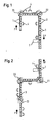
  • Figure 1 shows a plan view of an approximately U-shaped assembly line. She assigns one A large number of linear modules 1 and two rotary stations 21 and 22. The direction of transport is indicated by the arrows P. There is one to be produced on each module 1, 21, 22 Wandesse 3. Employees 4 perform various manufacturing steps on the assembly line by.
  • the wall meals 3 are related to the U-shape of the assembly line outward, i.e. the opening of the wall facing outwards.
  • a employee 4 performs a manufacturing step at the head of the wall fair, i.e. at that of the opening opposite end of the wall.
  • Another linear module is used the wall fairy conveyed to the turning station 21. In the present case, this is clockwise so that those in the leg of the assembly line adjoining on the right continued to be transported Wall food 3 also point outwards.
  • At the end of this leg of the assembly line is another Rotating station 22 arranged. Since the wall eating 3 for the further manufacturing steps the turning station 22 is set to the left.
  • a test station 5 is provided on the assembly line.
  • the individual modules namely linear modules 1 and turning stations 21 and 22, (in the application 14 pieces) are coupled in series like railroad cars and supplied with power, control and air lines via plug connections.
  • the segments or modules are 1200 mm wide, 850 mm high and 650 mm deep. They are for quick exchange respectively Conversion can be done on wheels without tools such as forklifts, pallet trucks etc. In the desired one Position they can be fixed with a locking spindle.
  • Each module 1, 21, 22 has one own separate decentralized drive with which an endless belt consisting of a Plastic hinge strap that is driven.
  • the turning stations 21 and 22 are also included an endless belt as a means of transport, which has the same width as the endless belt of the linear modules 1.
  • the turning stations 21 and 22 are also mobile and on the linear modules can be coupled using connectors.
  • the individual segments are selected by a central control unit (Profibus), not shown, and depending on Number of employees or the work content of the device to be produced as a workplace or buffer path. Segments or modules at the beginning of the line The end or end can also be switched off completely.
  • Profile central control unit
  • FIG. 2 An alternative form of the assembly line is shown in the top view of FIG. 2.
  • the assembly line consists of three legs, two of which are mutually related stand vertically.
  • the connection points of the linear modules 1 Legs in turn represent the turning stations 21 and 22.
  • a third turning station 23 is also provided, which has the function, the wall eating 3 for the further manufacturing process, the runs in the direction of arrows P to rotate 180 °.
  • a third embodiment of the present invention is shown in plan view in FIG. Again, the assembly line consists of three legs, which at the turning stations 21 and 22 are interconnected. In this variant, the individual legs but not connected at a 90 ° angle. Rather, this variant indicated that the turning stations 21 and 22 at any angle to the linear Module 1 can be coupled. This makes it available for the assembly line make optimal use of standing space. In Figure 3 it is also indicated that the employees positioned opposite each other on the assembly line on certain modules 1 provided that this is the space available and the manufacturing process allows.

Landscapes

  • Engineering & Computer Science (AREA)
  • Mechanical Engineering (AREA)
  • Automatic Assembly (AREA)
  • Control Of Position, Course, Altitude, Or Attitude Of Moving Bodies (AREA)

Abstract

Ein Montagesystem insbesondere für Küchengeräte soll flexibler gestaltet werden. Daher wird ein Montagesystem mit mehreren Modulen (1, 21, 22), die jeweils ein Montageband zur Aufnahme von zu fertigenden Bauteilen (3) aufweisen, und die zu einer Montagelinie aneinandergereiht sind, vorgeschlagen, welches mit einer Steuervorrichtung, mit der die mehreren Module (1, 21, 22) zentral mittels eines Bussystems steuerbar sind, versehen ist. Jeweils zwei der mehreren Module (1, 21, 22) sind durch eine Steckverbindungseinrichtung aneinander und damit an das Bussystem koppelbar. Damit lässt sich der Transport der zu fertigenden Bauteile gegebenenfalls mit entsprechender Sensorik in geeigneter Weise steuern. <IMAGE>

Description

Die vorliegende Erfindung betrifft ein Montagesystem mit mehreren Modulen, die jeweils ein Montageband zur Aufnahme von zu fertigenden Bauteilen aufweisen und die zu einer Montagelinie aneinandergereiht sind.
Zur Produktion von Küchengeräten, insbesondere Wandessen, haben sich Montagelinien als vorteilhaft erwiesen. Das zu fertigende Bauteil wird entlang dieser Montagelinie transportiert, und an beiden Seiten der Montagelinie führen mehrere Personen einzelne, spezifische Fertigungsschritte durch. Für die Ausführung jedes Fertigungsschritts ist das zu fertigende Bauteil für eine gewisse Zeit bei der betreffenden Person während seines Transports zu halten.
Aus der deutschen Offenlegungsschrift DE 40 40 090 A1 ist ein derartiges Montagesystem bekannt. Es ist ein lineares Montagesystem mit Paletten zur Aufnahme zu montierender Bauteile und mit einem Antrieb zur Fortbewegung der Paletten längs einer Montagebahn sowie mit einer Vorrichtung zur Rückführung der Paletten längs einer Rücktransportbahn zum Beginn der Montagebahn beschrieben. Die Palettenwechselzeit soll sehr stark herabgesetzt werden. Außerdem soll es möglich sein, bei Bedarf in sehr kurzer Zeit neue Bearbeitungsstationen zwischen schon bestehende einzufügen. Die Montagebahn und die Rücktransportbahn sind in gleich lange Module unterteilt, wobei eine Palette oder mehrere Paletten gemeinsam die Länge eines Moduls haben. Der Montagebahn ist eine Absenkvorrichtung nachgeschaltet, die eine Palette nach der anderen auf die Rücktransportbahn absenkt. Der Montagebahn ist ein Aufzug vorgeschaltet, der eine Palette nach der anderen am Ende der Rücktransportbahn vor dem Beginn der Montagebahn anhebt.
Des Weiteren ist aus dem deutschen Gebrauchsmuster DE 91 06 384 U1 ein Transportsystem bekannt, bei dem für jeden Wegabschnitt eine eigene Steuereinheit vorgesehen ist. Die Steuereinheiten benachbarter Wegabschnitte kommunizieren in bidirektionaler Weise miteinander, um die zu transportierenden Gegenstände von dem Transportmittel des einen Wegabschnitts auf dasjenige des in Transportrichtung angrenzenden Wegabschnitts zu überführen. Sämtliche Steuereinheiten sind untereinander identisch und gleichberechtigt, d.h. es gibt keinen Master. Eine bestehende Transportanlage kann um ein oder mehrere Antriebe beziehungsweise Transportmittel ergänzt oder verkürzt werden, ohne dass eine neue Steuerung erstellt werden müsste.
Die Aufgabe der vorliegenden Erfindung besteht darin, ein Montagesystem, bei dem ein Montageband als Werkstückträger dient, flexibler zu gestalten.
Erfindungsgemäß wird diese Aufgabe gelöst durch ein Montagesystem mit mehreren Modulen, die jeweils ein Montageband zur Aufnahme von zu fertigenden Bauteilen aufweisen und die zu einer Montagelinie aneinander gereiht sind, und einer Steuervorrichtung, mit der die mehreren Module zentral mittels eines Bussystems steuerbar sind, wobei zwei der mehreren Module jeweils durch eine Steckverbindungseinrichtung aneinander und damit an das Bussystem ankoppelbar sind.
Die Montagelinie kann so mit einer "zentralen Intelligenz" bei beliebiger Modulzahl gesteuert werden. Bei einem handelsüblichen Bussystem kann das Montagesystem beispielsweise auf 30 Segmente pro Montagelinie bedingt durch die Leitungswiderstände bei 24 V Steuerleitungen erweitert werden. Darüber hinaus ist die Montagelinie mit diesem Bussystem an beliebige andere Systeme zu koppeln. So ist beispielsweise der Signalaustausch zwischen Elektroprüfstand und Montagelinie oder optoelektronische Überwachung einzelner Baugruppen beziehungsweise Module oder aber auch eine elektronische Schraubüberwachung möglich.
Vorteilhafterweise sind die einzelnen Module über Steckverbinder miteinander koppelbar, wobei die Steckverbindungseinrichtungen eine Verbindung von Strom- und/oder Luftleitungen zur Versorgung der einzelnen Module erlauben. Dies bedeutet, dass Strom, Luft und sonstige Betriebsmittel von einem Modul auf das andere übertragen werden können.
Die Montagelinie kann eine oder mehrere Drehstationen zur Aufnahme eines zu fertigenden Bauteils aus einer ersten Richtung und zur Abgabe des zu fertigenden Bauteils in eine zweite, von der ersten unterschiedlichen Richtung aufweisen. Eine derartige Drehstation gewährleistet beliebige Richtungswechsel und unterschiedliche Drehrichtungen. Durch die Drehstationen kann z.B. auf der Innenseite der Montagelinie produziert und auf der gegenüberliegenden Seite vorgerüstet werden. Beim Loswechsel wird beispielsweise über ein Bedienpult der Drehwinkel von 90° auf 270° geändert, die Mitarbeiter gehen auf die andere Seite der Montagelinie, und es kann ohne Rüstzeit weiter produziert werden.
Zusätzlich zu den linearen Modulen und den Drehstationen kann beispielsweise ein mobiles Gestell als weiteres Standardelement für die Montagelinie eingesetzt werden. Das Gestell kann aus einem Aluminiumprofil hergestellt sein und eine Arbeitsplatzbeleuchtung, ein Ablagetableau und eine Steckdose aufweisen. Es kann wahlweise an jedes lineare Modul mechanisch und elektrisch gekoppelt werden. Dadurch wird aus dem linearen Modul ein vollwertiger Arbeitsplatz. In der Steuereinheit können lineare Module entweder als Transportstrecke (Puffer) oder als Arbeitsplatz geschaltet werden. Die Drehstationen sind immer Transportstrecke beziehungsweise Pufferplatz.
Das Montageband umfasst vorzugsweise eine endlose Kunststoffkette beziehungsweise ein Kunststoffscharnierband. Dieses wird durch einen dezentralen Antrieb angetrieben und stellt günstigerweise auch gleichzeitig eine Fertigungsfläche dar. Damit kann auf spezielle Werkstückträger, wie beispielsweise Paletten, die aufwändig zu transportieren sind, verzichtet werden.
Die Steuervorrichtung wird vorzugsweise zur Transportüberwachung verwendet, so dass ein Transport nur erfolgt, wenn auf einem bestimmten Modul der Fertigungsschritt beendet und das benachbarte Modul frei ist. Zur Steuerung können beispielsweise Lichttaster eingesetzt werden, die je nach Justierung das Werkstück an beliebiger Stelle des Moduls stoppen.
Durch minimierte Übergangsstellen zwischen den linearen Modulen und den Drehstationen kann die minimale Werkstückbreite beispielsweise auf 250 mm reduziert werden. Hinsichtlich Höhe, Tiefe und maximaler Breite bestehen jedoch keine Einschränkungen.
Vorteilhafterweise ist mindestens eines der Module, d.h. ein lineares Modul beziehungsweise eine Drehstation, elektromotorisch, hydraulisch oder pneumatisch höhenverstellbar. Günstig ist es, wenn diese Höhenverstellung stufenlos erfolgen kann. Somit läßt sich die Montagelinie an unterschiedlichste Fertigungsprozesse und ergonomische Anforderungen flexibel anpassen.
Durch den modularen Aufbau des Montagesystems und die Steckverbindungen für die Ansteuerungen kann eine Montagelinie binnen kürzester Zeit, z.B. 20 bis 30 Minuten in Länge und Richtung komplett umgebaut werden. Bei einem Defekt kann im Gegensatz zu starren Montagelinien ein einzelnes Segment beispielsweise in fünf Minuten ausgetauscht werden. Die Produktion kann dann unmittelbar weitergeführt und das entfernte, defekte Segment repariert werden. Es ist damit eine extrem hohe Flexibilität in der Anordnung, Ausstattung, Montagerichtung und Erweiterbarkeit beziehungsweise Kürzung der Linie gemäß einem Baukastensystem möglich.
Die modulare, zentral gesteuerte Montagelinie ist beispielsweise durch eine Kameraüberwachung aufrüstbar. Damit lassen sich Schraubvorgänge zählen und Etiketten oder Bauteile auf Position überprüfen sowie die Steuerung der Montagelinie beeinflussen.
Die vorliegende Erfindung wird nun anhand der beigefügten Zeichnungen näher erläutert, in den zeigen:
Figur 1
eine Draufsicht auf ein erfindungsgemäßes Montagesystem;
Figur 2
eine Draufsicht auf ein alternatives Montagesystem; und
Figur 3
eine Draufsicht auf ein weiteres, alternatives Montagesystem.
Die nachfolgend beschriebenen Ausführungsformen stellen bevorzugte Ausführungsbeispiele der vorliegenden Erfindung dar.
Figur 1 zeigt eine Draufsicht auf eine annähernd U-förmige Montagelinie. Sie weist eine Vielzahl linearer Module 1 und zwei Drehstationen 21 und 22 auf. Die Transportrichtung ist durch die Pfeile P angedeutet. Auf jedem Modul 1, 21, 22 befindet sich eine zu fertigende Wandesse 3. Mitarbeiter 4 führen an der Montagelinie verschiedene Fertigungsschritte durch.
Zu Beginn der Montagelinie sind die Wandessen 3 bezogen auf die U-Form der Montagelinie nach außen gerichtet, d.h. die Öffnung der Wandesse weist nach außen. Ein Mitarbeiter 4 führt einen Fertigungsschritt am Kopf der Wandesse, d.h. an dem der Öffnung der Wandesse gegenüberliegenden Ende, durch. Über ein weiteres lineares Modul wird die Wandesse zu der Drehstation 21 befördert. Diese ist im vorliegenden Fall rechtsdrehend, so dass die in dem rechts anschließenden Schenkel der Montagelinie weitertransportierten Wandessen 3 ebenfalls nach außen weisen. Zwei Mitarbeiter 4, die an der Außenseite des Montagesystems platziert sind, führen Fertigungsschritte an den ihnen zugewandten Wandessen durch. Am Ende dieses Schenkels der Montagelinie ist eine weitere Drehstation 22 angeordnet. Da die Wandessen 3 für die weiteren Fertigungsschritte nach innen weisen müssen, ist die Drehstation 22 linksdrehend eingestellt. Sie nimmt die jeweilige Wandesse auf, dreht um 90° nach links, d.h. gegen den Uhrzeigersinn, und gibt die Wandesse 3 an den anschließenden Schenkel der Montagelinie ab. Dort sitzen zwei Mitarbeiter an der Systeminnenseite und führen ihre spezifischen Fertigungsschritte an den ihnen zugewandten Wandessen durch. Am Ende der Fertigungsstraße beziehungsweise der Montagelinie ist ein Prüfplatz 5 vorgesehen.
Die einzelnen Module, nämlich Linearmodule 1 und Drehstationen 21 und 22, (im Anwendungsfall 14 Stück) werden vom Prinzip her wie Eisenbahnwaggons hintereinander gekoppelt und über Steckverbindungen mit Strom-, Steuer- und Luftleitungen versorgt. In bevorzugter Ausführungsform sind die Segmente beziehungsweise Module 1 1200 mm breit, 850 mm hoch und 650 mm tief. Sie sind zum raschen Austausch beziehungsweise Umbau ohne Hilfsmittel wie Stapler, Hubwagen etc. auf Rädern fahrbar. In der gewünschten Position sind sie mit einer Feststellspindel fixierbar. Jedes Modul 1, 21, 22 hat einen eigenen separaten dezentralen Antrieb, mit dem ein Endlosgurt, bestehend aus einem Kunststoffscharnierband, angetrieben wird. Die Drehstationen 21 und 22 sind auch mit einem Endlosgurt als Transportmittel versehen, der die gleiche Breite besitzt wie der Endlosgurt der linearen Module 1. Die Drehstationen 21 und 22 sind ebenfalls fahrbar und an die linearen Module durch Steckverbinder koppelbar. Die einzelnen Segmente werden von einer nicht dargestellten, zentralen Steuereinheit (Profibus) angewählt und je nach Anzahl der Mitarbeiter oder des Arbeitsinhaltes des zu produzierenden Geräts als Arbeitsplatz oder Pufferstrecke kodiert. Segmente beziehungsweise Module am Bandanfang oder -ende können auch komplett ausgeschaltet werden.
Eine alternative Form der Montagelinie ist in der Draufsicht von Figur 2 dargestellt. Wiederum besteht die Montagelinie aus drei Schenkeln, von denen jeweils zwei zueinander senkrecht stehen. Die Verbindungspunkte der durch die linearen Module 1 gebildeten Schenkel stellen wiederum die Drehstationen 21 und 22 dar. In dem langen nach unten weisenden Schenkel von Figur 2 ist darüber hinaus eine dritte Drehstation 23 vorgesehen, die die Funktion besitzt, die Wandessen 3 für den weiteren Fertigungsprozess, der in Richtung der Pfeile P verläuft, um 180° zu drehen.
Eine dritte Ausführungsform der vorliegenden Erfindung ist in Figur 3 in Draufsicht dargestellt. Wiederum besteht die Montagelinie aus drei Schenkeln, die an den Drehstationen 21 und 22 miteinander verbunden sind. Bei dieser Variante sind die einzelnen Schenkel jedoch nicht im 90°-Winkel miteinander verbunden. Vielmehr wird durch diese Variante angedeutet, dass die Drehstationen 21 und 22 in einem beliebigen Winkel an die linearen Module 1 gekoppelt werden können. Dadurch läßt sich der für die Montagelinie zur Verfügung stehende Raum optimal ausnützen. In Figur 3 ist ferner angedeutet, dass die Mitarbeiter an der Montagelinie an bestimmten Modulen 1 einander gegenüber positioniert werden können, sofern dies der zur Verfügung stehende Raum und der Fertigungsprozess zulässt.
Claims (8)

  1. Montagesystem mit
    mehreren Modulen (1, 21, 22), die jeweils ein Montageband zur Aufnahme von zu fertigenden Bauteilen (3) aufweisen und die zu einer Montagelinie aneinander gereiht sind,
    gekennzeichnet durch
    eine Steuervorrichtung, mit der die mehreren Module zentral mittels eines Bussystems steuerbar sind, wobei zwei der mehreren Module (1, 21, 22) jeweils durch eine Steckverbindungseinrichtung aneinander und damit an das Bussystem ankoppelbar sind.
  2. Montagesystem nach Anspruch 1, wobei über die Steckverbindungseinrichtung auch Strom- und/oder Luftleitungen zur Versorgung der einzelnen Module koppelbar sind.
  3. Montagesystem nach Anspruch 1 oder 2, wobei jedes der mehreren Module über eine standardisierte Steuerleitung an externe Geräte anschließbar ist.
  4. Montagesystem nach einem der Ansprüche 1 bis 3, wobei mindestens eines der mehreren Module (1, 21, 22) der Montagelinie eine Drehstation (21, 22) zur Aufnahme eines zu fertigenden Bauteils (3) aus einer ersten Richtung und Abgabe des zu fertigenden Bauteils (3) in eine zweite, von der ersten unterschiedlichen Richtung ist.
  5. Montagesystem nach einem der Ansprüche 1 bis 4, wobei das Montageband eine endlose Kunststoffkette als Werkstückträger umfasst.
  6. Montagesystem nach Anspruch 5, wobei das Montageband als Fertigungsfläche nutzbar ist.
  7. Montagesystem nach einem der Ansprüche 1 bis 6, wobei die Steuervorrichtung zur Transportüberwachung verwendbar ist, so dass ein Transport von einem ersten zu einem zweiten Modul (1, 21, 22) nur erfolgt, wenn ein Fertigungsschritt auf dem ersten Modul beendet und das zweite Modul frei ist.
  8. Montagesystem nach einem der Ansprüche 1 bis 7, wobei eines der mehreren Module (1, 21, 22) elektromotorisch, hydraulisch oder pneumatisch höhenverstellbar ist.
EP03026949A 2002-12-30 2003-11-25 Montagesystem Withdrawn EP1435275A1 (de)

Applications Claiming Priority (2)

Application Number Priority Date Filing Date Title
DE2002161379 DE10261379A1 (de) 2002-12-30 2002-12-30 Montagesystem
DE10261379 2002-12-30

Publications (1)

Publication Number Publication Date
EP1435275A1 true EP1435275A1 (de) 2004-07-07

Family

ID=32478049

Family Applications (1)

Application Number Title Priority Date Filing Date
EP03026949A Withdrawn EP1435275A1 (de) 2002-12-30 2003-11-25 Montagesystem

Country Status (3)

Country Link
EP (1) EP1435275A1 (de)
DE (1) DE10261379A1 (de)
RS (1) RS101003A (de)

Cited By (3)

* Cited by examiner, † Cited by third party
Publication number Priority date Publication date Assignee Title
EP1980358A1 (de) * 2007-04-13 2008-10-15 Friul Filiere SpA Stützrahmen für eine Produktionsanlage
DE102009042565A1 (de) * 2009-09-17 2011-04-07 Morath Systems E.K. Signalgesteuerter Arbeitsplatz, Funktionsmodul für einen signalgesteuerten Arbeitsplatz und Produktionsverfahren an einem signalgesteuerten Arbeitsplatz
EP2985113A4 (de) * 2013-04-12 2016-11-16 Ntn Toyo Bearing Co Ltd Produktionsanlage

Families Citing this family (1)

* Cited by examiner, † Cited by third party
Publication number Priority date Publication date Assignee Title
DE102019204709A1 (de) * 2019-04-02 2020-10-08 cellumation GmbH Vorrichtung und Verfahren zur Verbesserung der Kommunikation von modularen Fördersystemen

Citations (7)

* Cited by examiner, † Cited by third party
Publication number Priority date Publication date Assignee Title
US4209898A (en) * 1977-09-12 1980-07-01 Hitachi, Ltd. Assembly line for parts of electronic and other equipments
DE3413255A1 (de) * 1984-04-07 1985-10-17 Krone Gmbh, 1000 Berlin Verfahren und vorrichtung fuer ein modulares, flexibles montagesystem
EP0340639A1 (de) * 1988-04-30 1989-11-08 Siegmund Kumeth Montageanlage
US5402880A (en) * 1988-08-18 1995-04-04 Rexnord Corporation Article carrying chain having free tab
DE19729369A1 (de) * 1997-07-09 1999-01-21 Teamtechnik Maschinen Und Anla Bearbeitungsstraße
JP2001347431A (ja) * 2000-06-05 2001-12-18 Sharp Corp 作業台及びこれを用いた生産システム
US20020010527A1 (en) * 2000-04-27 2002-01-24 Wayne Wielebski Driver board control system for modular conveyor with address-based network for inter-conveyer communication

Patent Citations (7)

* Cited by examiner, † Cited by third party
Publication number Priority date Publication date Assignee Title
US4209898A (en) * 1977-09-12 1980-07-01 Hitachi, Ltd. Assembly line for parts of electronic and other equipments
DE3413255A1 (de) * 1984-04-07 1985-10-17 Krone Gmbh, 1000 Berlin Verfahren und vorrichtung fuer ein modulares, flexibles montagesystem
EP0340639A1 (de) * 1988-04-30 1989-11-08 Siegmund Kumeth Montageanlage
US5402880A (en) * 1988-08-18 1995-04-04 Rexnord Corporation Article carrying chain having free tab
DE19729369A1 (de) * 1997-07-09 1999-01-21 Teamtechnik Maschinen Und Anla Bearbeitungsstraße
US20020010527A1 (en) * 2000-04-27 2002-01-24 Wayne Wielebski Driver board control system for modular conveyor with address-based network for inter-conveyer communication
JP2001347431A (ja) * 2000-06-05 2001-12-18 Sharp Corp 作業台及びこれを用いた生産システム

Non-Patent Citations (1)

* Cited by examiner, † Cited by third party
Title
PATENT ABSTRACTS OF JAPAN vol. 2002, no. 04 4 August 2002 (2002-08-04) *

Cited By (4)

* Cited by examiner, † Cited by third party
Publication number Priority date Publication date Assignee Title
EP1980358A1 (de) * 2007-04-13 2008-10-15 Friul Filiere SpA Stützrahmen für eine Produktionsanlage
DE102009042565A1 (de) * 2009-09-17 2011-04-07 Morath Systems E.K. Signalgesteuerter Arbeitsplatz, Funktionsmodul für einen signalgesteuerten Arbeitsplatz und Produktionsverfahren an einem signalgesteuerten Arbeitsplatz
EP2985113A4 (de) * 2013-04-12 2016-11-16 Ntn Toyo Bearing Co Ltd Produktionsanlage
US10569374B2 (en) 2013-04-12 2020-02-25 Ntn Corporation Production facility

Also Published As

Publication number Publication date
RS101003A (sr) 2006-12-15
DE10261379A1 (de) 2004-08-05

Similar Documents

Publication Publication Date Title
DE19729369C2 (de) Autarker Bearbeitungsplatz und daraus bestehende Bearbeitungsstraße
DE3522127C2 (de)
DE2756422C2 (de) Fertigungsanlage für in mehreren Schritten herzustellende Bauteile
DE19741671B4 (de) Bearbeitungsplatz
WO2015132378A1 (de) Fertigungsstation, fertigungsanlage und verfahren
WO2008003462A1 (de) Modulare bearbeitungsvorrichtung
DE4006486B4 (de) Gehäuseteil für eine Arbeits- oder Bearbeitungsstation einer Fertigungsanlage
DE102006002082A1 (de) Bearbeitungsplatz für eine Bearbeitungsstraße mit einer Modulplattform und darin einführbaren Moduleinschüben
DE102014102990A1 (de) Fertigungsstation
EP0255027A2 (de) Montageeinrichtung
EP2070647B1 (de) Modulare Fertigungslinie
EP0192816A2 (de) Arbeitsplatzanordnung
DE102019007764A1 (de) Werkstückwagen sowie Werkzeugmaschine und Fertigungszelle mit derartigem Werkstückwagen
EP1435275A1 (de) Montagesystem
DE69700882T2 (de) Werkzeugmaschine zur bearbeitung bei hoher geschwindigkeit mit ergonomischer anordnung von funktionsteilen
DE2937472A1 (de) Transfermaschine
DE3942594A1 (de) Einrichtung zum foerdern von werkstuecken bzw. werkstuecktraegern
DE102013000037B4 (de) polygonaler Rundtakttisch
EP1163973A2 (de) Maschinentisch für eine Bearbeitungsmachine
EP0105223B1 (de) Maschine zum Bohren und Einsetzen von Beschlagteilen in plattenförmige Werkstücke
DE4001590A1 (de) Grossteil-stufenpresse
EP0245317B1 (de) Hochfrequenz-schweissanlage
DE102012201641A1 (de) Fördervorrichtung
DE4445888A1 (de) Vorrichtung für die Montage von Fensterflügeln und anderen Gegenständen
DE3713652C2 (de)

Legal Events

Date Code Title Description
PUAI Public reference made under article 153(3) epc to a published international application that has entered the european phase

Free format text: ORIGINAL CODE: 0009012

AK Designated contracting states

Kind code of ref document: A1

Designated state(s): AT BE BG CH CY CZ DE DK EE ES FI FR GB GR HU IE IT LI LU MC NL PT RO SE SI SK TR

AX Request for extension of the european patent

Extension state: AL LT LV MK

RTI1 Title (correction)

Free format text: MONTAGESYSTEM

17P Request for examination filed

Effective date: 20050107

AKX Designation fees paid

Designated state(s): AT BE BG CH CY CZ DE DK EE ES FI FR GB GR HU IE IT LI LU MC NL PT RO SE SI SK TR

STAA Information on the status of an ep patent application or granted ep patent

Free format text: STATUS: THE APPLICATION IS DEEMED TO BE WITHDRAWN

18D Application deemed to be withdrawn

Effective date: 20060328