EP1434695B1 - Security element - Google Patents
Security element Download PDFInfo
- Publication number
- EP1434695B1 EP1434695B1 EP02776977A EP02776977A EP1434695B1 EP 1434695 B1 EP1434695 B1 EP 1434695B1 EP 02776977 A EP02776977 A EP 02776977A EP 02776977 A EP02776977 A EP 02776977A EP 1434695 B1 EP1434695 B1 EP 1434695B1
- Authority
- EP
- European Patent Office
- Prior art keywords
- layer
- security element
- pattern
- pattern elements
- light
- Prior art date
- Legal status (The legal status is an assumption and is not a legal conclusion. Google has not performed a legal analysis and makes no representation as to the accuracy of the status listed.)
- Expired - Lifetime
Links
- 239000010410 layer Substances 0.000 claims abstract description 73
- 239000012790 adhesive layer Substances 0.000 claims abstract description 12
- 239000011241 protective layer Substances 0.000 claims abstract description 8
- 239000002131 composite material Substances 0.000 claims description 16
- 229910052751 metal Inorganic materials 0.000 claims description 10
- 239000002184 metal Substances 0.000 claims description 10
- 239000002966 varnish Substances 0.000 claims description 7
- 229910052782 aluminium Inorganic materials 0.000 claims description 4
- XAGFODPZIPBFFR-UHFFFAOYSA-N aluminium Chemical compound [Al] XAGFODPZIPBFFR-UHFFFAOYSA-N 0.000 claims description 4
- 230000001419 dependent effect Effects 0.000 claims description 3
- 238000001228 spectrum Methods 0.000 claims description 2
- 229910052714 tellurium Inorganic materials 0.000 claims description 2
- PORWMNRCUJJQNO-UHFFFAOYSA-N tellurium atom Chemical compound [Te] PORWMNRCUJJQNO-UHFFFAOYSA-N 0.000 claims description 2
- PXHVJJICTQNCMI-UHFFFAOYSA-N Nickel Chemical compound [Ni] PXHVJJICTQNCMI-UHFFFAOYSA-N 0.000 claims 2
- 239000004411 aluminium Substances 0.000 claims 2
- VYZAMTAEIAYCRO-UHFFFAOYSA-N Chromium Chemical compound [Cr] VYZAMTAEIAYCRO-UHFFFAOYSA-N 0.000 claims 1
- RYGMFSIKBFXOCR-UHFFFAOYSA-N Copper Chemical compound [Cu] RYGMFSIKBFXOCR-UHFFFAOYSA-N 0.000 claims 1
- BQCADISMDOOEFD-UHFFFAOYSA-N Silver Chemical compound [Ag] BQCADISMDOOEFD-UHFFFAOYSA-N 0.000 claims 1
- 239000011651 chromium Substances 0.000 claims 1
- 229910052804 chromium Inorganic materials 0.000 claims 1
- 229910052802 copper Inorganic materials 0.000 claims 1
- 239000010949 copper Substances 0.000 claims 1
- PCHJSUWPFVWCPO-UHFFFAOYSA-N gold Chemical compound [Au] PCHJSUWPFVWCPO-UHFFFAOYSA-N 0.000 claims 1
- 229910052737 gold Inorganic materials 0.000 claims 1
- 239000010931 gold Substances 0.000 claims 1
- 229910052759 nickel Inorganic materials 0.000 claims 1
- 238000012216 screening Methods 0.000 claims 1
- 229910052709 silver Inorganic materials 0.000 claims 1
- 239000004332 silver Substances 0.000 claims 1
- 239000004922 lacquer Substances 0.000 abstract description 11
- 239000000463 material Substances 0.000 description 6
- 239000011888 foil Substances 0.000 description 3
- 238000000034 method Methods 0.000 description 3
- 239000003973 paint Substances 0.000 description 3
- 230000007704 transition Effects 0.000 description 3
- 230000005670 electromagnetic radiation Effects 0.000 description 2
- 238000005516 engineering process Methods 0.000 description 2
- 238000005286 illumination Methods 0.000 description 2
- 238000004519 manufacturing process Methods 0.000 description 2
- 230000005855 radiation Effects 0.000 description 2
- 230000003595 spectral effect Effects 0.000 description 2
- 239000006096 absorbing agent Substances 0.000 description 1
- 230000008033 biological extinction Effects 0.000 description 1
- 239000011248 coating agent Substances 0.000 description 1
- 238000000576 coating method Methods 0.000 description 1
- 230000001427 coherent effect Effects 0.000 description 1
- 238000011161 development Methods 0.000 description 1
- 230000018109 developmental process Effects 0.000 description 1
- 239000003292 glue Substances 0.000 description 1
- 229910052736 halogen Inorganic materials 0.000 description 1
- 150000002367 halogens Chemical class 0.000 description 1
- 230000003287 optical effect Effects 0.000 description 1
- WXZMFSXDPGVJKK-UHFFFAOYSA-N pentaerythritol Chemical compound OCC(CO)(CO)CO WXZMFSXDPGVJKK-UHFFFAOYSA-N 0.000 description 1
- 239000002985 plastic film Substances 0.000 description 1
- 229920006255 plastic film Polymers 0.000 description 1
- 239000005020 polyethylene terephthalate Substances 0.000 description 1
- 229920000139 polyethylene terephthalate Polymers 0.000 description 1
- 238000002310 reflectometry Methods 0.000 description 1
- 238000001429 visible spectrum Methods 0.000 description 1
- 230000000007 visual effect Effects 0.000 description 1
Images

Classifications
-
- B—PERFORMING OPERATIONS; TRANSPORTING
- B42—BOOKBINDING; ALBUMS; FILES; SPECIAL PRINTED MATTER
- B42D—BOOKS; BOOK COVERS; LOOSE LEAVES; PRINTED MATTER CHARACTERISED BY IDENTIFICATION OR SECURITY FEATURES; PRINTED MATTER OF SPECIAL FORMAT OR STYLE NOT OTHERWISE PROVIDED FOR; DEVICES FOR USE THEREWITH AND NOT OTHERWISE PROVIDED FOR; MOVABLE-STRIP WRITING OR READING APPARATUS
- B42D25/00—Information-bearing cards or sheet-like structures characterised by identification or security features; Manufacture thereof
- B42D25/30—Identification or security features, e.g. for preventing forgery
- B42D25/36—Identification or security features, e.g. for preventing forgery comprising special materials
- B42D25/373—Metallic materials
-
- B—PERFORMING OPERATIONS; TRANSPORTING
- B42—BOOKBINDING; ALBUMS; FILES; SPECIAL PRINTED MATTER
- B42D—BOOKS; BOOK COVERS; LOOSE LEAVES; PRINTED MATTER CHARACTERISED BY IDENTIFICATION OR SECURITY FEATURES; PRINTED MATTER OF SPECIAL FORMAT OR STYLE NOT OTHERWISE PROVIDED FOR; DEVICES FOR USE THEREWITH AND NOT OTHERWISE PROVIDED FOR; MOVABLE-STRIP WRITING OR READING APPARATUS
- B42D25/00—Information-bearing cards or sheet-like structures characterised by identification or security features; Manufacture thereof
- B42D25/30—Identification or security features, e.g. for preventing forgery
- B42D25/328—Diffraction gratings; Holograms
-
- B—PERFORMING OPERATIONS; TRANSPORTING
- B42—BOOKBINDING; ALBUMS; FILES; SPECIAL PRINTED MATTER
- B42D—BOOKS; BOOK COVERS; LOOSE LEAVES; PRINTED MATTER CHARACTERISED BY IDENTIFICATION OR SECURITY FEATURES; PRINTED MATTER OF SPECIAL FORMAT OR STYLE NOT OTHERWISE PROVIDED FOR; DEVICES FOR USE THEREWITH AND NOT OTHERWISE PROVIDED FOR; MOVABLE-STRIP WRITING OR READING APPARATUS
- B42D25/00—Information-bearing cards or sheet-like structures characterised by identification or security features; Manufacture thereof
- B42D25/20—Information-bearing cards or sheet-like structures characterised by identification or security features; Manufacture thereof characterised by a particular use or purpose
- B42D25/29—Securities; Bank notes
-
- B—PERFORMING OPERATIONS; TRANSPORTING
- B42—BOOKBINDING; ALBUMS; FILES; SPECIAL PRINTED MATTER
- B42D—BOOKS; BOOK COVERS; LOOSE LEAVES; PRINTED MATTER CHARACTERISED BY IDENTIFICATION OR SECURITY FEATURES; PRINTED MATTER OF SPECIAL FORMAT OR STYLE NOT OTHERWISE PROVIDED FOR; DEVICES FOR USE THEREWITH AND NOT OTHERWISE PROVIDED FOR; MOVABLE-STRIP WRITING OR READING APPARATUS
- B42D25/00—Information-bearing cards or sheet-like structures characterised by identification or security features; Manufacture thereof
- B42D25/30—Identification or security features, e.g. for preventing forgery
- B42D25/324—Reliefs
-
- B—PERFORMING OPERATIONS; TRANSPORTING
- B42—BOOKBINDING; ALBUMS; FILES; SPECIAL PRINTED MATTER
- B42D—BOOKS; BOOK COVERS; LOOSE LEAVES; PRINTED MATTER CHARACTERISED BY IDENTIFICATION OR SECURITY FEATURES; PRINTED MATTER OF SPECIAL FORMAT OR STYLE NOT OTHERWISE PROVIDED FOR; DEVICES FOR USE THEREWITH AND NOT OTHERWISE PROVIDED FOR; MOVABLE-STRIP WRITING OR READING APPARATUS
- B42D25/00—Information-bearing cards or sheet-like structures characterised by identification or security features; Manufacture thereof
- B42D25/30—Identification or security features, e.g. for preventing forgery
- B42D25/351—Translucent or partly translucent parts, e.g. windows
-
- B—PERFORMING OPERATIONS; TRANSPORTING
- B42—BOOKBINDING; ALBUMS; FILES; SPECIAL PRINTED MATTER
- B42D—BOOKS; BOOK COVERS; LOOSE LEAVES; PRINTED MATTER CHARACTERISED BY IDENTIFICATION OR SECURITY FEATURES; PRINTED MATTER OF SPECIAL FORMAT OR STYLE NOT OTHERWISE PROVIDED FOR; DEVICES FOR USE THEREWITH AND NOT OTHERWISE PROVIDED FOR; MOVABLE-STRIP WRITING OR READING APPARATUS
- B42D25/00—Information-bearing cards or sheet-like structures characterised by identification or security features; Manufacture thereof
- B42D25/40—Manufacture
- B42D25/45—Associating two or more layers
- B42D25/465—Associating two or more layers using chemicals or adhesives
- B42D25/47—Associating two or more layers using chemicals or adhesives using adhesives
Definitions
- the invention relates to an optically diffractive security element according to the preamble of claim 1.
- Such security elements are used to authenticate documents, such as Securities, checks, banknotes, credit cards, identity cards of all kinds, Entry tickets, tickets, etc., are used, with the security elements For example, as a thin layer composite is glued to the document.
- the security element is one of one Laminate cut piece of foil with a flat, reflective Reflective layer. In area parts that have an individual identifier on the area form the film piece, the reflective layer is removed, so that one under the Reflection layer arranged black layer is visible. On the of the Copy machine produced copy disappears the black identifier in the Reproduction of the remaining mirror surface, since the surface parts in which the Reflection layer is removed, and the remaining mirror surface in the copy appear uniformly black.
- Another security element has instead the plane mirror surfaces a hologram structure with the identifier and behaves like the ones discussed in the next paragraph Diffraction structures. In the copy, the identifier is in the copied image of the Hologram therefore recognizable.
- the invention is based on the object, a cost optically variable security element to create that of a photocopier not can be reproduced and not with holographic methods can be copied.
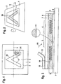
- FIG. 1 signify a document, 2 a security element, 3 a Background area, 4 a pattern element and 5 an imaginary, in the plane of Document 1 tilting axis.
- Document 1 is in directional artificial light illuminated laterally and obliquely from above and viewed vertically from above.
- the security element 2 is attached on the document 1, the security element 2 is attached.
- the security element 2 has for identification a pattern 25 of the pattern elements 4, which from the background surfaces 3 are surrounded.
- the pattern 25 consists of a single Pattern element 4 and forms a simple "V" character. In a practical Execution are more of the background surfaces 3 and the pattern elements. 4 arranged to the pattern 25.
- the pattern 25 is not visible to an observer, because there is no contrast between the pattern element 4 and the background surface 3 is present and both surfaces, both the background surface 3 and the Pattern element 4, appear dark, for example, metallic matt.
- the pattern element 4 lifts dark of the light. Background area 3 and is therefore good for the observer visible, noticeable.
- FIG. 3 shows the security element 2 (FIG. 2) in cross section, wherein the Cutting plane, for example, the tilt axis 5 (Fig. 2) contains.
- the Security element 2 consists of a layer composite 6 of a variety of Layers 7, 8, 9 and 11. Examples of the structure of the composite layer 6 and the for the composite layer 6 suitable materials are EP 0 401 466 A1 and US 4,856,857.
- the layer composite 6 comprises at least one Protective layer 7, an adhesive layer 8, one between the protective layer 7 and the , Adhesive layer 8 arranged paint layer 9.
- the adhesive layer 8 connects the Security element 2 with the document 1.
- the reflectivity is therefore due to a arranged at the interface Reflective layer 11, which forms a thin layer ( ⁇ 0.4 microns) of a Metal or one with a suitable inorganic dielectric layer coated metal, wherein the dielectric layer on the incident Light 10 facing side of the metal is arranged.
- the materials for the reflection layer 11 are shown in Tables 1 to 5 of US 4,856,857; Tables 1 to 6 are expressly in this Description included.
- the tellurium not mentioned in Table 5 is suitable also for the reflection layer 11.
- With the incident light 10 is daylight or Visually visible polychromatic light with wavelengths between Meant 380 nm and 780 nm.
- the layer composite 6 that of the lacquer layer 9 opposite surface of the cover layer 7 of the composite layer 6 by means of a Separating layer 12 connected to a carrier tape 13 to the transfer of the To facilitate fragile layer composite 6 on the document 1.
- the carrier tape 13 made of paper or a plastic film, e.g. PC or PETP, can be after the Glue the layer composite 6 remove so that the pattern 25 (Fig. 2) by the protective layer 7 and the lacquer layer 9 is visible therethrough. This is on the already mentioned in the beginning GB 2 129 739 B referenced.
- paint coating 9 is in the region of Pattern elements 4 a relief structure 14 with a geometric profile depth p shaped.
- the lacquer layer 9 is flat and smooth and is parallel to the other layers of the composite layer. 6
- the material of the adhesive layer 8 fills the depressions of the relief structure 14. Die Interface with or without additional reflective layer 11 follows both the Relief structure 14 as well as mirror planes of the background surfaces 3.
- Such Relief structures 14 absorb almost everything incident on the pattern elements 4 visible light 10 and scatter a small fraction of the incident light 10 in the half space above the pattern element 4 back.
- the percentage of absorbed light 10 depends in a non-linear manner on the structure depth h and can by means of the choice of the structure depth h in the above range between 50% and about 99% are controlled, where, the flatter the relief structure 14 the more incident light 10 is backscattered and the less light 10 is absorbed.
- the given percentages apply to the relief structure 14 with a reflection layer 11 of, for example, aluminum. Abutting Regions of the pattern elements 4 with different texture depths h therefore show a gray scale.
- the embodiment of the relief structure 14 shown in FIG. 4 is a cross lattice formed by two sinusoidal base lattices intersecting at right angles.
- the sine function of the first basic lattice extending along the coordinate x has a period d x and an amplitude h x
- the sine function of the second base lattice extending along the coordinate y has a period d y and an amplitude h y .
- h (x, y) h x • sin 2 ( ⁇ x / d x ) + h y • sin 2 ( ⁇ y / d y ), rectangular or pyramidal structures are used as the interface h (x, y).
- the structure depth h [h x + h y ] can be chosen larger than the period d, but the relief structure 14 is difficult to produce with today's production methods.
- the interface h (x, y) is similar to an egg carton and is shown in FIG.
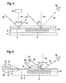
- the optical behavior of the security element 2 is included in FIG. 5 a first observation condition explained.
- the incident light 10 forms with a normal 15 to the level of the security element 2 an angle of about 40 °.
- the pattern elements 4 absorb with the described relief structure 14 in the visible range up to 95% of incident light 10, the rest is scattered.
- the reflecting background surface 3 however, only about 10% of the incident light 10 absorbs and reflects that rest. Since surface parts of the pattern elements 4 to the specular Background surfaces 3 adjoin, therefore results for the observer so strong contrast, that on a given background surface 3 of the Security elements 2 arranged in the predetermined pattern 25
- Pattern elements 4 are easily recognizable as information.
- the pattern 25 stops Logo, text, picture or other graphic sign.
- the drawing of Figure 5 corresponds to the lighting conditions in Copy machine.
- the Document 1 scatters the incident light 10 into the whole half space. Thereby scattered light is arranged in a direction of the normal 15 Light receiver 16 of the copier.
- the incident light 10 falls below the same Incidence angle ⁇ on the pattern element 4, the incident light 10, however practically absorbed; both the light receiver 16 and the observer 19 register no light from the pattern element 4.
- the pattern element 4 is therefore dark.
- the background surfaces 3 form for the incident in the layer composite 6
- Light 10 the plane mirror surfaces of the pattern 25, while the pattern elements 4 as absorber surfaces swallow the incident light 10 for the most part. Therefore, the observer 19 recognizes the background surfaces in the reflected light 17 3 as intensely bright partial surfaces and the pattern elements 4 as dark partial surfaces of the pattern 25. Scattered in directions other than that of the reflected light 17 the security element 2 only a small part of the incident light 10.
- the Intensities per unit area of the background surfaces 3 and the Pattern elements 4 scattered light are practically the same size, so that no Contrast between the background areas 3 and the pattern elements 4 is available.
- In the illumination with the directional incident light 10 is the from the background surfaces 3 and the pattern elements 4 formed pattern 25 in Contrary to a black and white image produced by printing technology only in that when specular reflection reflected light 17 recognizable.
- the background surface 3 and the pattern member 4 throw so small a portion of the incident light 10 into the light receiver 16 that the copying machine reproduces the background field 3 and the pattern element 4 indiscriminately as black areas.
- the advantage of this security element 2 is that the copying machine can not reproduce the information represented by the pattern element 4, while the observer 19, who in directed incident light 10 almost automatically tilts the security element 2 in such a way that he regards the background area 3 in reflection, the information of the pattern element 4 with great contrast in front of the background surface 3 sees.
- the security element 2 can thus easily be distinguished by an attentive observer from reflecting metal foils on good color copies of the document 1.
- a further advantage is the use of the relief structure 14 in the security element 2 with the periods d x (FIG. 4), d y (FIG. 4), which are shorter than the wavelengths of the coherent light sources usable for holographic copying methods; Therefore, a copy of the security element 2 can not be produced with the holographic methods.
- FIG. 6 shows a second illumination condition for the two observers 19, 20 of the security element 2.
- a polychromatic radiation source 21, eg halogen lamp, incandescent lamp etc., is arranged above the second observer 20 and transmits the incident light 10 to the pattern element 4 at a large angle of incidence ⁇ of approximately 60 ° to 80 °.
- the first observer 19 recognizes the pattern 25 (Fig. 2) of the pattern elements 4 against the background 3 (Fig. 5) at the reflection angle ⁇ , as stated above. If the periods d x (FIG. 4), d y (FIG.
- the diffracted light 22 includes the short wavelength part of the visually visible spectrum of the electromagnetic radiation.
- the diffracted light 22 is therefore in a cyan to violet color depending on the diffraction angle ⁇ and the periods d x , d y .
- the color of the diffracted light 22 observed at a predetermined diffraction angle ⁇ to the normal 15 also depends on the azimuth in intensity. Note: In the above consideration, the refractive influence of the protective layer 7 has been disregarded.
- the first observer 19 looks in the direction of the reflected light Light 17 and recognizes the background surfaces 3 as shiny bright faces and the pattern elements 4 as dark faces of the pattern 25th
- the diffracted light 22 can no longer be seen by the second observer 20 in the direction of the coordinate x or y, since the relief structure 14 no longer diffracts any visible light 22.
- the color of the visible under the reflection angle ⁇ pattern elements. 3 depends on the nature of the reflection layer 11, since different Combinations of the materials in and on the reflective layer 11 the incident Light 10 not in the whole spectral range of the visible electromagnetic Reflect radiation evenly. Deep black pattern elements 3 have with Advantage a gradual transition of the refractive index of the paint layer 9 to Reflection layer 11; the transition is by means of at least one layer of a inorganic dielectric 23 between the resist layer 9 and a Metal layer 24 of the reflection layer 11 is generated. For the flat mirror surface the background surfaces 3 affects those of the dielectric 23 and the Metal layer 24 formed reflective layer 11 is not noticeable.
- the Grayscale by means of different dense grid with grid points of less than 0.4 mm dimension produced. It is irrelevant whether the Halftone dots as a background field 3 in a pattern element 4 or as Pattern element 4 are arranged in the background field 3.
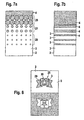
- FIGS. 7a and 7b show further examples for the production of Grayscale within a security element 2 from the dark pattern element 4 until the bright shiny background field 3 shown.
- FIGS. 7a and 7b show further examples for the production of Grayscale within a security element 2 from the dark pattern element 4 until the bright shiny background field 3 shown.
- FIG. 7a are in one fixed grid of a maximum of 0.5 mm spacing according to the gray level different sized grid points used.
- a lightly brightened zone 26 touch the grid points, in a brightened zone 27 have the Halftone dots have an average dimension of about 0.25 mm while in one slightly darkened zone 28, the grid points have about 0.15 mm.
- FIG. 7b is a line grid with a maximum of 0.5 mm instead of the dot grid , Distance used.
- a corresponding line width causes the here Grayscale in zones 26 ( Figures 7a) to 28 ( Figure 7a).
- the grid points of the pattern areas 4 the same dimensions.
- a very fine gray gradation is by means of correspondingly stepped structure depths h in the relief structures 14 (FIG. 6) reached, which is sufficient for the reproduction of a black and white photo.
- two patterns 25 of the security element 2 are simple Example shown.
- the Pattern 25 from a ribbon 29 with a star 30.
- the ribbon 29 is from the dark pattern element 4 is formed.
- the environment of the band 29 and the star 30 form the bright background areas 3. Without limitation of the date Described are the background surfaces 3 and the pattern elements 4 interchangeable, as shown in the lower half of the security element 2 is.
- the security element 2 in Fig. 1 will be even more difficult to duplicate if the pattern 25 is a background for a mosaic-like surface pattern 31 forms with diffraction structures whose spatial frequencies have values in the range 300 lines per mm to 2000 lines per mm.
- Such mosaic Surface patterns 31 are from the above-mentioned EP 0 105 099 A1, EP 0 330 738 A1, EP 0 375 833 A1. The content of these patents is hereby incorporated in the description included.
Landscapes
- Engineering & Computer Science (AREA)
- Manufacturing & Machinery (AREA)
- Business, Economics & Management (AREA)
- Accounting & Taxation (AREA)
- Chemical Kinetics & Catalysis (AREA)
- General Chemical & Material Sciences (AREA)
- General Health & Medical Sciences (AREA)
- Toxicology (AREA)
- Health & Medical Sciences (AREA)
- Chemical & Material Sciences (AREA)
- Finance (AREA)
- Credit Cards Or The Like (AREA)
- Diffracting Gratings Or Hologram Optical Elements (AREA)
- Medicines Containing Antibodies Or Antigens For Use As Internal Diagnostic Agents (AREA)
- Bidet-Like Cleaning Device And Other Flush Toilet Accessories (AREA)
- Burglar Alarm Systems (AREA)
- Laminated Bodies (AREA)
Abstract
Description
Die Erfindung bezieht sich auf ein optisch diffraktives Sicherheitselement
gemäss dem Oberbegriff des Anspruchs 1.The invention relates to an optically diffractive security element
according to the preamble of
Solche Sicherheitselemente werden zur Beglaubigung von Dokumenten, wie Wertpapiere, Cheques, Banknoten, Kreditkarten, Ausweisen aller Art, Eintrittsbillette, Fahrscheine usw., eingesetzt, wobei die Sicherheitselemente beispielsweise als dünner Schichtverbund auf das Dokument geklebt ist.Such security elements are used to authenticate documents, such as Securities, checks, banknotes, credit cards, identity cards of all kinds, Entry tickets, tickets, etc., are used, with the security elements For example, as a thin layer composite is glued to the document.
Moderne Kopiergeräte für Farbkopien stellen für drucktechnisch hergestellte Dokumente ein erhebliches Gefahrenpotential dar, weil die visuellen Unterschiede zwischen dem Original und der Kopie so gering sind, dass nur ein mit den entsprechenden Hilfsmitteln ausgerüsteter Fachmann das Original von der Kopie unterscheiden kann, wobei oft andere Kriterien, wie Intagliodruck, Wasserzeichen, Fluoreszenz, optisch variable Sicherheitselemente mit Beugungsstrukturen usw., als das Aussehen des Druckbilds herangezogen werden müssen.Modern copying machines for color copies provide for printing technology produced Documents pose a significant potential hazard because of the visual differences between the original and the copy are so small that only one with the appropriate specialist equipped the original of the copy often other criteria such as intaglio printing, watermarks, Fluorescence, optically variable security elements with diffraction structures etc., must be used as the appearance of the printed image.
Aus der EP 0 522 217 B1 ist bekannt, dass auf einem Dokument angeordnete, spiegelnde Folienstücke einen guten Schutz gegen unerlaubtes Kopieren solcher Dokumente bewirken. Der Unterschied zwischen dem Original mit den spiegelnden Folienstücken und einer Kopie ist klar erkennbar, da die Kopiermaschinen spiegelnde Flächen schwarz wiedergeben. Allerdings sind spiegelnde Folien im Handel leicht erhältlich. Die schwarzen Flächen in solchen Kopien sind daher leicht mit spiegelnder Folie zu überkleben, um die Kopie echter aussehen zu lassen.From EP 0 522 217 B1 it is known that on a document arranged, reflecting pieces of film good protection against unauthorized Copy of such documents cause. The difference between the original with the reflecting foil pieces and a copy is clearly recognizable, since the Copy machines reflect reflective surfaces in black. However, they are Reflective films readily available commercially. The black areas in such Copies are therefore easy to cover with reflective film to make the copy more genuine to look like.
Die DE 44 10 431 A1 beschreibt Weiterentwicklungen der oben beschriebenen Folienstücke. Das Sicherheitselement ist ein aus einem Schichtverbund geschnittenes Folienstück mit einer ebenen, spiegelnden Reflexionsschicht. In Flächenteilen, die eine individuelle Kennung auf der Fläche des Folienstücks bilden, ist die Reflexionsschicht entfernt, so dass eine unter der Reflexionsschicht angeordnete schwarze Schicht sichtbar wird. Auf der von der Kopiermaschine hergestellten Kopie verschwindet die schwarze Kennung in der Wiedergabe der verbliebenen Spiegelfläche, da die Flächenteile, in denen die Reflexionsschicht entfernt ist, und die verbliebene Spiegelfläche in der Kopie gleichmässig schwarz erscheinen. Ein anderes Sicherheitselement weist anstelle der ebenen Spiegelflächen eine Hologrammstruktur mit der Kennung auf und verhält sich beim Kopieren wie die im nächsten Absatz abgehandelten Beugungsstrukturen. In der Kopie ist die Kennung im kopierten Bild des Hologramms daher erkennbar.DE 44 10 431 A1 describes further developments of the above described film pieces. The security element is one of one Laminate cut piece of foil with a flat, reflective Reflective layer. In area parts that have an individual identifier on the area form the film piece, the reflective layer is removed, so that one under the Reflection layer arranged black layer is visible. On the of the Copy machine produced copy disappears the black identifier in the Reproduction of the remaining mirror surface, since the surface parts in which the Reflection layer is removed, and the remaining mirror surface in the copy appear uniformly black. Another security element has instead the plane mirror surfaces a hologram structure with the identifier and behaves like the ones discussed in the next paragraph Diffraction structures. In the copy, the identifier is in the copied image of the Hologram therefore recognizable.
Es ist auch z.B. aus GB 2 129 739 B bekannt, wertvolle Dokumente mit einem optisch variablen Sicherheitselement mit Beugungsstrukturen (z.B. Hologramme, mosaikartige Flächenmuster aus diffraktiven Flächenelementen beispielsweise gemäss EP 0 105 099 A1, EP 0 330 738 A1, EP 0 375 833 A1, usw.) auszurüsten. Diese Sicherheitselemente weisen ein Muster oder Bild auf, das sich abhängig von der Betrachtungsbedingung ändert. Für Unbefugte sind diese Sicherheitselemente nur mit grossem Aufwand nachzumachen. Leider sind in der Farbkopie des Dokuments eines der Muster bzw. Bildes des Sicherheitselementes wiedergeben, das im Original unter der Betrachtungsbedingung sichtbar ist, die im Kopiergerät für die Abbildung festgelegt ist. Natürlich ist in der Kopie keine Veränderung des Musters oder Bildes beim Verändern der Betrachtungsbedingung mehr zu erkennen, aber bei Unaufmerksamkeit des Empfängers kann leicht eine Kopie für das echte Dokument gehalten werden.It is also e.g. From GB 2 129 739 B known, valuable documents with a optically variable security element having diffractive structures (e.g., holograms, mosaic-like surface patterns of diffractive surface elements, for example according to EP 0 105 099 A1, EP 0 330 738 A1, EP 0 375 833 A1, etc.). These security items have a pattern or image that is dependent changes from the viewing condition. For unauthorized persons these are Imitate security elements only with great effort. Unfortunately, in the Color copy of the document of one of the patterns or images of the security element which is visible in the original under the viewing condition, which is in the Copier is set for the picture. Of course, in the copy is no Change of pattern or picture when changing the View condition more to recognize, but inattention of the Recipient can easily be kept a copy for the real document.
Ausführungen des Schichtverbunds für die Sicherheitselemente und dazu verwendbare Materialien beschreiben die EP 0 401 466 A1 und US 4 856 857.Versions of the layer composite for the security elements and thereto usable materials are described in EP 0 401 466 A1 and US Pat. No. 4,856,857.
Der Erfindung liegt die Aufgabe zugrunde, ein kostengünstiges optisch variables Sicherheitselement zu schaffen, das von einem Kopiergerät nicht wiedergegeben werden kann und auch nicht mit holographischen Methoden kopiert werden kann.The invention is based on the object, a cost optically variable security element to create that of a photocopier not can be reproduced and not with holographic methods can be copied.
Die genannte Aufgabe wird erfindungsgemäss durch die im Kennzeichen des
Anspruchs 1 angegebenen Merkmale gelöst. Vorteilhafte Ausgestaltungen der
Erfindung ergeben sich aus den abhängigen-Ansprüchen. The object is achieved according to the invention by the in the plate of the
Claim specified
Ausführungsbeispiele der Erfindung sind in der Zeichnung dargestellt und werden im folgenden näher beschrieben.Embodiments of the invention are illustrated in the drawing and will be described in more detail below.
Es zeigen:
Figur 1- ein Dokument,
Figur 2- das um eine Achse gekippte Dokument,
Figur 3- ein Sicherheitselement im Querschnitt,
Figur 4- die Grenzfläche einer Reliefstruktur,
Figur 5- eine erste Beobachtungsbedingung,
Figur 6- eine zweite Beobachtungsbedingung,
- Figur 7a, 7b
- das Sicherheitselement mit Graustufen und
Figur 8- eine Reliefstruktur.
- FIG. 1
- a document,
- FIG. 2
- the document tilted about an axis,
- FIG. 3
- a security element in cross section,
- FIG. 4
- the interface of a relief structure,
- FIG. 5
- a first observation condition,
- FIG. 6
- a second observation condition,
- Figure 7a, 7b
- the security element with grayscale and
- FIG. 8
- a relief structure.
In der Figur 1 bedeuten 1 ein Dokument, 2 ein Sicherheitselement, 3 eine
Hintergrundfläche, 4 ein Musterelement und 5 eine gedachte, in der Ebene des
Dokuments 1 liegende Kippachse. Das Dokument 1 ist im gerichteten Kunstlicht
seitlich und schräg von oben beleuchtet und senkrecht von oben betrachtet. Auf
dem Dokument 1 ist das Sicherheitselement 2 befestigt. Das Sicherheitselement 2
weist zur Identifizierung ein Muster 25 aus den Musterelementen 4 auf, die von
den Hintergrundflächen 3 umgeben sind. Um die Zeichnung der Figur 1
übersichtlich zu gestalten, besteht das Muster 25 aus einem einzigen
Musterelement 4 und bildet ein einfaches "V"-Zeichen. In einer praktischen
Ausführung sind mehrere der Hintergrundflächen 3 und der Musterelemente 4
zum Muster 25 angeordnet. Unter den genannten Beleuchtungs- und
Betrachtungsbedingungen ist für einen Beobachter das Muster 25 nicht sichtbar,
da zwischen dem Musterelement 4 und der Hintergrundfläche 3 kein Kontrast
vorhanden ist und beide Flächen, sowohl die Hintergrundfläche 3 als auch das
Musterelement 4, erscheinen dunkel, beispielsweise metallisch matt. Im diffusen
Tageslicht oder bei diffuser Raumbeleuchtung hingegen und bei weiter unten
genannten, bestimmten Beleuchtungsbedingungen hebt sich das Musterelement 4
dunkel von der hellen. Hintergrundfläche 3 ab und ist daher für den Beobachter gut
sichtbar.In the figure 1 1 signify a document, 2 a security element, 3 a
Background area, 4 a pattern element and 5 an imaginary, in the plane of
ist, wie die Figur 2 zeigt, das Dokument 1 mit dem Sicherheitselement 2 um
die Kippachse 5 derart gekippt, dass die Hintergrundfläche 3 Licht in das Auge
des Beobachters spiegelt, erkennt der Beobachter das Muster 25, da das
Musterelement 4 dunkel bleibt und sich mit hohem Kontrast von der
Hintergrundfläche 3 abhebt. Unter diesen Beobachtungsbedingung ist die
Reflexionsbedingung für den Beobachter erfüllt. Eine Drehung des
Sicherheitselements 2 in seiner Ebene verändert für den Beobachter das
Aussehen des Musters 25 in der Reflexionsbedingung nicht, d.h. eine azimutale
Ausrichtung des Sicherheitselements 2 ist nicht vorzunehmen.is, as the figure 2 shows the
Die Figur 3 zeigt das Sicherheitselement 2 (Fig. 2) im Querschnitt, wobei die
Schnittebene beispielsweise die Kippachse 5 (Fig. 2) enthält. Das
Sicherheitselement 2 besteht aus einem Schichtverbund 6 aus einer Vielzahl von
Schichten 7, 8, 9 und 11. Beispiele für den Aufbau des Schichtverbunds 6 und die
für den Schichtverbund 6 geeigneten Materialien sind der EP 0 401 466 A1 und
der US 4 856 857 zu entnehmen.FIG. 3 shows the security element 2 (FIG. 2) in cross section, wherein the
Cutting plane, for example, the tilt axis 5 (Fig. 2) contains. The
Im einfachsten Fall umfasst der Schichtverbund 6 wenigstens eine
Schutzschicht 7, eine Klebeschicht 8, eine zwischen der Schutzschicht 7 und der
. Klebeschicht 8 angeordnete Lackschicht 9. Die Klebeschicht 8 verbindet das
Sicherheitselement 2 mit dem Dokument 1. Eine Grenzfläche zwischen der
Klebeschicht 8 und der Lackschicht 9 reflektiert durch die Deckschicht 7 und die
Lackschicht 9 einfallendes Licht 10, wenn sich der Brechungsindex an der
Grenzschicht beim Übergang von der Lackschicht 9 in die Klebeschicht 8
sprunghaft ändert. Mit den Materialien in der Tabelle 6 der US 4 856 857 fällt die
Differenz in den Brechzahlen zu klein aus, um eine starke Reflexion zu erhalten.
Das Reflexionsvermögen wird daher durch eine an der Grenzfläche angeordnete
Reflexionsschicht 11 erhöht, die eine dünne Schicht (< 0,4 Mikrometer) aus einem
Metall oder aus einem mit einer geeigneten anorganischen dielektrischen Schicht
überzogenen Metall ist, wobei die dielektrische Schicht auf der dem einfallenden
Licht 10 zugewandten Seite des Metalls angeordnet ist.In the simplest case, the
Die Materialien für die Reflexionsschicht 11 sind in den Tabellen 1 bis 5 der
US 4 856 857 enthalten; die Tabellen 1 bis 6 sind ausdrücklich in diese
Beschreibung eingeschlossen. Das in der Tabelle 5 nicht erwähnte Tellur eignet
sich auch für die Reflexionsschicht 11. Mit dem einfallenden Licht 10 ist Tageslicht
oder visuell sichtbares polychromatisches Licht mit Wellenlängen zwischen
380 nm und 780 nm gemeint. The materials for the
In einer Ausführung des Schichtverbunds 6 ist die von der Lackschicht 9
abgewandte Oberfläche der Deckschicht 7 des Schichtverbunds 6 mittels einer
Trennschicht 12 mit einem Trägerband 13 verbunden, um den Transfer des
fragilen Schichtverbunds 6 auf das Dokument 1 zu erleichtern. Das Trägerband 13
aus Papier oder einer Kunststoffolie, z.B. PC oder PETP, lässt sich nach dem
Aufkleben des Schichtverbunds 6 entfernen, so dass das Muster 25 (Fig. 2) durch
die Schutzschicht 7 und die Lackschicht 9 hindurch sichtbar ist. Hierzu wird auf die
bereits eingangs erwähnte GB 2 129 739 B verwiesen.In one embodiment of the
Wie aus der Figur 3 ersichtlich, ist in die Lackschicht 9 im Bereich der
Musterelemente 4 eine Reliefstruktur 14 mit einer geometrischen Profiltiefe p
abgeformt. Im Bereich der Hintergrundflächen 3 ist die Lackschicht 9 eben und
glatt geformt und ist parallel zu den anderen Schichten des Schichtverbunds 6.
Das Material der Klebeschicht 8 verfüllt die Vertiefungen der Reliefstruktur 14. Die
Grenzfläche mit oder ohne zusätzliche Reflexionsschicht 11 folgt sowohl der
Reliefstruktur 14 als auch Spiegelebenen der Hintergrundflächen 3.As can be seen from FIG. 3,
Die Reliefstruktur 14 ist ein Kreuzgitter aus zwei Basisgittem mit Perioden d
kleiner als eine Grenzwellenlänge λ am kurzwelligen Ende im Spektrum des
sichtbaren Lichts, d.h. λ = 380 nm bis λ = 420 nm und weist eine optisch wirksame
Strukturtiefe h, das ist die Profiltiefe p multipliziert mit dem Brechungsindex der
Lackschicht 9, vorzugsweise im Bereich von h = 50 nm bis h = 500 nm auf. Solche
Reliefstrukturen 14 absorbieren fast alles auf die Musterelemente 4 einfallende
sichtbare Licht 10 und streuen einen kleinen Bruchteil des einfallenden Lichts 10
in den Halbraum über dem Musterelement 4 zurück. Der Prozentsatz des
absorbierten Lichts 10 hängt in nicht linearer Weise von der Strukturtiefe h ab und
kann mittels der Wahl der Strukturtiefe h im oben genannten Bereich zwischen
50% und etwa 99 % gesteuert werden, wobei gilt, je flacher die Reliefstruktur 14
desto mehr einfallendes Licht 10 wird rückgestreut und desto weniger Licht 10
wird absorbiert. Die angegebenen Prozentsätze gelten für die Reliefstruktur 14 mit
einer Reflexionsschicht 11 aus beispielsweise Aluminium. Aneinanderstossende
Bereiche der Musterelemente 4 mit verschiedenen Strukturtiefen h zeigen daher
eine Grauabstufung.The
Die in der Figur 4 gezeigte Ausführung der Reliefstruktur 14 ist ein durch
zwei rechtwinklig sich kreuzende, sinusförmige Basisgitter gebildetes Kreuzgitter.
Die sich längs der Koordinate x ausdehnende Sinusfunktion des ersten
Basisgitters weist eine Periode dx und eine Amplitude hx auf, während die sich
längs der Koordinate y ausdehnende Sinusfunktion des zweiten Basisgitters eine
Periode dy und eine Amplitude hy hat. Über der durch die Koordinaten x und y
aufgespannten Ebene folgt die durch das Kreuzgitter geformte Grenzfläche h(x, y)
im Schichtverbund 6 (Fig. 3) beispielsweise der Funktion
In anderen Ausführungen sind h(x, y) = hx•sin2(πx/dx) + hy•sin2(πy/dy), Rechteck- oder Pyramidenstrukturen als Grenzfläche h(x, y) verwendet.In other embodiments, h (x, y) = h x • sin 2 (πx / d x ) + h y • sin 2 (π y / d y ), rectangular or pyramidal structures are used as the interface h (x, y).
In einer Ausführung sind die beiden Perioden dx, dy und die Strukturtiefen
hx; hy gleich, in andem Ausführungen verschieden. Die Strukturtiefe h = [hx + hy]
kann grösser als die Periode d gewählt werden, jedoch ist die Reliefstruktur 14 mit
den heutigen Herstellmethoden schwierig herzustellen. Die Grenzfläche h(x, y)
gleicht einem Eierkarton und ist in der Figur 4 dargestellt.In one embodiment, the two periods d x , d y and the texture depths h x ; h y same, different in other versions. The structure depth h = [h x + h y ] can be chosen larger than the period d, but the
Anhand der Figur 5 ist das optische Verhalten des Sicherheitselements 2 bei
einer ersten Beobachtungsbedingung erklärt. Das einfallende Licht 10 bildet mit
einer Normalen 15 zur Ebene des Sicherheitselements 2 einen Winkel von etwa
40°. In einem Beispiel absorbieren die Musterelemente 4 mit der
vorbeschriebenen Reliefstruktur 14 im sichtbaren Bereich bis zu 95% des
einfallenden Lichts 10, der Rest wird gestreut. Die spiegelnde Hintergrundfläche 3
hingegen absorbiert nur etwa 10% des einfallenden Lichts 10 und reflektiert das
übrige. Da Flächenteile der Musterelemente 4 an die spiegelnde
Hintergrundflächen 3 angrenzen, ergibt sich für den Beobachter daher ein so
starker Kontrast, dass die auf einer vorgegebenen Hintergrundfläche 3 des
Sicherheitselements 2 im vorbestimmten Muster 25 angeordneten
Musterelemente 4 leicht als Information erkennbar sind. Das Muster 25 stellt ein
Logo, einem Text, ein Bild oder ein anderes graphisches Zeichen dar.The optical behavior of the
Die Zeichnung der Figur 5 entspricht den Beleuchtungsverhältnissen im
Kopiergerät. Je nach Modell des Kopiergeräts bildet das gerichtete, auf das
Dokument 1 und das Sicherheitselement 2 einfallende Licht 10 des Kopiergeräts
mit der Normalen 15 den Einfallswinkel α im Bereich von etwa 40° bis 50°. Das
Dokument 1 streut das einfallende Licht 10 in den ganzen Halbraum. Dadurch
gelangt gestreutes Licht in einen in Richtung der Normalen 15 angeordneten
Lichtempfänger 16 des Kopiergeräts. Im Gegensatz dazu wird das von der
Hintergrundfläche 3 reflektierte Licht 17 nach dem Reflexionsgesetz mit dem
gleichen Winkel α in eine Blickrichtung 18 des Beobachters 19 abgelenkt und
gelangt nicht in den Lichtempfänger 16. Fällt das Licht 10 unter dem gleichen
Einfallswinkel α auf das Musterelement 4, wird das einfallende Licht 10 hingegen
praktisch absorbiert; sowohl der Lichtempfänger 16 als auch der Beobachter 19
registrieren kein Licht vom Musterelement 4. Das Musterelement 4 ist daher
dunkel.The drawing of Figure 5 corresponds to the lighting conditions in
Copy machine. Depending on the model of the copier, the directional, on the
Die Hintergrundflächen 3 bilden für das in den Schichtverbund 6 einfallende
Licht 10 die ebenen Spiegelflächen des Musters 25, während die Musterelemente
4 als Absorberflächen das einfallende Licht 10 zum grössten Teil verschlucken.
Daher erkennt der Beobachter 19 im reflektierten Licht 17 die Hintergrundflächen
3 als intensiv helle Teilflächen und die Musterelemente 4 als dunkle Teilflächen
des Musters 25. In anderen Richtungen als die des reflektierten Lichts 17 streut
das Sicherheitselement 2 nur einen geringen Teil des einfallenden Lichts 10. Die
Intensitäten pro Flächeneinheit des an den Hintergrundflächen 3 und den
Musterelementen 4 gestreuten Lichts sind praktisch gleich gross, so dass kein
Kontrast zwischen den Hintergrundflächen 3 und den Musterelementen 4
vorhanden ist. Bei der Beleuchtung mit dem gerichtet einfallenden Licht 10 ist das
aus den Hintergrundflächen 3 und den Musterelementen 4 gebildete Muster 25 im
Gegensatz zu einem drucktechnisch hergestellten Schwarz-Weissbild nur in dem
bei Spiegelreflexion reflektierten Licht 17 erkennbar.The background surfaces 3 form for the incident in the
Im Kopiergerät werfen die Hintergrundfläche 3 und das Musterelement 4
einen so kleinen Anteil des einfallenden Lichts 10 in den Lichtempfänger 16, dass
das Kopiergerät das Hintergrundfeld 3 und das Musterelement 4 unterschiedslos
als schwarze Flächen wiedergibt. Der Vorteil dieses Sicherheitselements 2 liegt
darin, dass das Kopiergerät die durch das Musterelement 4 dargestellte
Information nicht wiedergeben kann, während der Beobachter 19, der bei gerichtet
einfallenden Licht 10 fast automatisch das Sicherheitselement 2 so kippt, dass er
die Hintergrundfläche 3 in Reflexion betrachtet, die Information des
Musterelements 4 mit grossem Kontrast vor der Hintergrundfläche 3 erblickt. Das
Sicherheitselement 2 ist auf diese Weise von einem aufmerksamen Beobachter
leicht von spiegelnden Metallfolien auf guten Farbkopien des Dokuments 1 zu
unterscheiden. Ein weiterer Vorteil bildet die Verwendung der Reliefstruktur 14 im
Sicherheitselement 2 mit den Perioden dx (Fig. 4), dy (Fig. 4), die kürzer sind als
die Wellenlängen der für holographische Kopiermethoden nutzbaren kohärenten
Lichtquellen; eine Kopie des Sicherheitselements 2 ist mit den holographischen
Methoden daher nicht herstellbar.In the copying machine, the
In der Figur 6 ist eine für die beiden Beobachter 19, 20 des
Sicherheitselements 2 zweite Beleuchtungsbedingung dargestellt. Eine
polychromatische Strahlungsquelle 21, z.B. Halogenlampe, Glühlampe usw., ist
über dem zweiten Beobachter 20 angeordnet und sendet das einfallende Licht 10
unter einem grossen Einfallswinkel α von etwa 60° bis 80° auf das Musterelement
4. Der erste Beobachter 19 erkennt das Muster 25 (Fig. 2) der Musterelemente 4
vor dem Hintergrund 3 (Fig. 5) unter dem Reflexionswinkel α, wie oben
ausgeführt. Falls die Perioden dx (Fig. 4), dy (Fig. 4) der Reliefstruktur 14 im
Bereich einer halben und einer ganzen Grenzwellenlänge λ liegen; d.h.
λ ≥ d ≥ λ/2, wobei d = dx bzw. dy ist, wird ein Teil des einfallenden Lichts 10 unter
einem grossen Beugungswinkel β in die minus erste Ordnung als gebeugtes Licht
22 abgelenkt. Der zweite Beobachter 20 vermag das gebeugte Licht 22 zu
erkennen. Das gebeugte Licht 22 umfasst den kurzwelligen Teil des visuell
sichtbaren Spektrums der elektromagnetischen Strahlung. Das gebeugte Licht 22
ist daher abhängig vom Beugungswinkel β und den Perioden dx, dy in einer blaugrünen
bis violetten Farbe. Die unter einem vorbestimmten Beugungswinkel β zur
Normalen 15 beobachtete Farbe des gebeugten Lichts 22 hängt in der Intensität
auch vom Azimut ab. Anmerkung: In der obigen Betrachtung ist der refraktive
Einfluss der Schutzschicht 7 ausser acht gelassen worden.FIG. 6 shows a second illumination condition for the two
Der erste Beobachter 19 hingegen blickt in die Richtung des reflektierten
Lichts 17 und erkennt die Hintergrundflächen 3 als glänzend helle Teilflächen und
die Musterelemente 4 als dunkle Teilflächen des Musters 25.The
Ist die Periode dx, bzw. dy kleiner als λ/2, kann in der Richtung der
Koordinate x bzw. y das gebeugte Licht 22 vom zweiten Beobachter 20 nicht mehr
gesehen werden, da die Reliefstruktur 14 kein sichtbares Licht 22 mehr beugt. Der
erste Beobachter 19, der das Sicherheitselement 2 unter dem Reflexionswinkel α
beobachtet, erblickt unter diesen Bedingungen die Musterelemente 4 unverändert
in einer dunkelbraunen bis schwarzen Farbe. If the period d x or d y is smaller than λ / 2, the diffracted light 22 can no longer be seen by the
Die Farbe der unter dem Reflexionswinkel α sichtbaren Musterelemente 3
hängt von der Beschaffenheit der Reflexionsschicht 11 ab, da verschiedene
Kombinationen der Materialien in und an der Reflexionsschicht 11 das einfallende
Licht 10 nicht im ganzen Spektralbereich der sichtbaren elektromagnetischen
Strahlung gleichmässig reflektieren. Tief schwarze Musterelemente 3 weisen mit
Vorteil einen allmählichen Uebergang der Brechzahl von der Lackschicht 9 zur
Reflexionsschicht 11 auf; der Uebergang ist mittels wenigstens einer Schicht eines
anorganischen Dielektrikum 23 zwischen der Lackschicht 9 und einer
Metallschicht 24 der Reflexionsschicht 11 erzeugt. Für die ebene Spiegelfläche
der Hintergrundflächen 3 wirkt sich die aus dem Dielektrikum 23 und der
Metallschicht 24 gebildete Reflexionsschicht 11 nicht merkbar aus. Bei der
Reliefstruktur 14 hingegen bewirkt diese Reflexionsschicht 11 infolge von
Interferenzen eine nahezu vollständige Auslöschung des einfallenden Lichts 10,
die vor allem gleichmässig über dem ganzen Spektralbereich der sichtbaren
elektromagnetischen Strahlung erfolgt. Ein Beispiel weist eine 50 nm dicke Schicht
des Dielektrikums 23 aus ZnS und 100 nm Aluminium als Metallschicht 24 auf. Ein
weiterer Vorteil ist die durch den hohen Brechungsindex für ZnS von n= 2,4
gegenüber dem Brechungsindex der Lackschicht 9 von n = 1,5 vergrösserte
Strukturtiefe h bei gleichbleibender Profiltiefe p der Reliefstruktur 14.The color of the visible under the reflection angle α pattern elements. 3
depends on the nature of the
Neben den Grauabstufungen mit Musterelementen 4 mit verschiedenen
Strukturtiefen h sind in einer Ausführung des Sicherheitselements 2 die
Grauabstufung mittels verschieden dichter Rasterung mit Rasterpunkten von
weniger als 0,4 mm Abmessung erzeugt. Dabei ist es unerheblich, ob die
Rasterpunkte als Hintergrundfeld 3 in einem Musterelement 4 oder als
Musterelement 4 im Hintergrundfeld 3 angeordnet sind.In addition to the gray scale with
In den Figuren 7a und 7b sind weitere Beispiele zur Erzeugung von
Graustufen innerhalb eines Sicherheitselements 2 vom dunklen Musterelement 4
bis zum hellglänzenden Hintergrundfeld 3 gezeigt. In der Figur 7a sind in einem
fixen Raster von maximal 0,5 mm Abstand entsprechend der Graustufe
verschieden grosse Rasterpunkte eingesetzt. In einer leicht aufgehellten Zone 26
berühren sich die Rasterpunkte, in einer aufgehellten Zone 27 weisen die
Rasterpunkte eine mittlere Abmessung von etwa 0,25 mm auf, während in einer
leicht abgedunkelten Zone 28 die Rasterpunkte etwa 0,15 mm aufweisen. In der
Figur 7b ist anstelle des Punktrasters ein Linienraster mit maximal 0,5 mm
. Abstand eingesetzt. Eine entsprechende Linienbreite bewirkt hier die
Grauabstufung in den Zonen 26 (Fig. 7a) bis 28 (Fig. 7a).FIGS. 7a and 7b show further examples for the production of
Grayscale within a
In einer der Zonen 26 bis 28 weisen die Rasterpunkte der Musterflächen 4
die gleichen Abmessungen auf. Ein sehr feine Grauabstufung wird mittels der
entsprechend abgestuften Strukturtiefen h in den Reliefstrukturen 14 (Fig. 6)
erreicht, die für die Wiedergabe eines Schwarz-Weiss-Photos ausreichend ist.In one of the
In der Figur 8 sind zwei Muster 25 des Sicherheitselements 2 als einfaches
Beispiel gezeigt. In der oberen Hälfte des Sicherheitselements 2 besteht das
Muster 25 aus einem Band 29 mit einem Stern 30. Das Band 29 ist aus dem
dunklen Musterelement 4 gebildet. Die Umgebung des Bands 29 und der Stern 30
bilden die hellen Hintergrundflächen 3. Ohne Einschränkung des bisher
Beschriebenen sind die Hintergrundflächen 3 und die Musterelemente 4
vertauschbar, wie dies in der unteren Hälfte des Sicherheitselements 2 dargestellt
ist.In FIG. 8, two
Das Sicherheitselement 2 in Fig. 1 wird noch schwieriger nachzumachen,
wenn das Muster 25 einen Hintergrund für ein mosaikartiges Flächenmuster 31
mit Beugungsstrukturen bildet, deren Spatialfrequenzen Werte im Bereich
300 Linien pro mm bis 2000 Linien pro mm aufweisen. Solche mosaikartiges
Flächenmuster 31 sind aus den eingangs erwähnten EP 0 105 099 A1, EP 0 330
738 A1, EP 0 375 833 A1 bekannt. Der Inhalt dieser Patentschriften ist hiermit in
die Beschreibung eingeschlossen.The
Claims (13)
- Security element (2) having a pattern (25) comprising subareas and in the form of a layer composite (6) for authenticating a document (1), which composite comprises at least one transparent protective layer (7), a transparent varnish layer (9) and an adhesive layer (8), the varnish layer (9) being arranged between the protective layer (7) and the adhesive layer (8) and the refractive index changing abruptly at the interface between the adhesive layer (8) and the varnish layer (9), and the subareas of the pattern (25) being composed of background areas (3) and pattern elements (4),
characterized in that, in the region of the background areas (3), the varnish layer (9) is smooth and flat and, in the region of the pattern elements (4), relief structures (14) having a predetermined optically active structure depth (h) are moulded into the varnish layer (9),
in that the background areas (3) are flat reflective areas for light (10) falling into the layer composite (6), and
in that the relief structures (14) are crossed gratings formed of basic gratings with periods (dx; dy) and the periods (dx; dy) are shorter than a predetermined limiting wavelength (λ) at the short-wave end in the spectrum of visible light (10), so that the pattern elements (4) absorb and scatter the incident light (10), the ratio of the absorbed and of the scattered light in each relief structure (14) being dependent in a predetermined manner on the optically active structure depth (h) prevailing in the relief structure (14). - Security element (2) according to Claim 1, characterized in that the crossed grating of the relief structures (14) is composed of two basic gratings arranged substantially perpendicular to each other and having the periods (dx; dy).
- Security element (2) according to Claim 1 or 2, characterized in that the basic gratings are sinusoidal.
- Security element (2) according to one of Claims 1 to 3, characterized in that at least one of the periods (dx; dy) is longer than half the limiting wavelength (λ) but shorter than the limiting wavelength (λ).
- Security element (2) according to one of Claims 1 to 4, characterized in that the limiting wavelength (λ) is chosen in the range between 380 nm and 420 nm.
- Security element (2) according to one of Claims 1 to 5, characterized in that the periods (dx; dy) of the two basic gratings have the same value.
- Security element (2) according to one of Claims 1 to 6, characterized in that the values for the optically active structure depth (h) of the relief structures (14) are chosen in the range from h = 50 nm to h = 500 nm.
- Security element (2) according to one of Claims 1 to 7, characterized in that the reflective layer (11) contains a metal from the group comprising aluminium, silver, gold, chromium, copper, nickel and tellurium.
- Security element (2) according to Claim 8, characterized in that the reflective layer (11) on the side of the metal layer (24) facing the varnish layer (9) has at least one layer of an inorganic dielectric (23).
- Security element (2) according to Claim 9, characterized in that the layer of inorganic dielectric (23) consists of ZnS and the metal layer (24) consists of aluminium.
- Security element (2) according to one of Claims 1 to 10, characterized in that the pattern (25) has zones (26; 27; 28) with grey steps, and that the pattern elements (4) of the zones (26; 27; 28) having different grey steps differ in the optically active structure depth (h) of the relief structures (14).
- Security element (2) according to one of Claims 1 to 10, characterized in that the pattern (25) has zones (26; 27; 28) with grey steps, in that the pattern elements (4) have identical values of the optically active structure depths (h), and in that the zones (26; 27; 28) differ in differently dense screening of halftone points with dimensions of less than 0.4 mm.
- Security element (2) according to one of Claims 1 to 12, characterized in that the pattern (25) forms a background for a mosaic-like surface pattern (31) comprising diffraction structures with spatial frequencies in the range from 300 lines per mm to 2000 lines per mm.
Applications Claiming Priority (3)
| Application Number | Priority Date | Filing Date | Title |
|---|---|---|---|
| DE10150293A DE10150293B4 (en) | 2001-10-12 | 2001-10-12 | security element |
| DE10150293 | 2001-10-12 | ||
| PCT/EP2002/009861 WO2003033274A1 (en) | 2001-10-12 | 2002-09-04 | Security element |
Publications (2)
| Publication Number | Publication Date |
|---|---|
| EP1434695A1 EP1434695A1 (en) | 2004-07-07 |
| EP1434695B1 true EP1434695B1 (en) | 2005-02-02 |
Family
ID=7702235
Family Applications (1)
| Application Number | Title | Priority Date | Filing Date |
|---|---|---|---|
| EP02776977A Expired - Lifetime EP1434695B1 (en) | 2001-10-12 | 2002-09-04 | Security element |
Country Status (16)
| Country | Link |
|---|---|
| US (1) | US7145723B2 (en) |
| EP (1) | EP1434695B1 (en) |
| JP (1) | JP4315334B2 (en) |
| KR (1) | KR100910098B1 (en) |
| CN (1) | CN1268501C (en) |
| AT (1) | ATE288364T1 (en) |
| AU (1) | AU2002339482B2 (en) |
| CA (1) | CA2462924C (en) |
| DE (2) | DE10150293B4 (en) |
| ES (1) | ES2236594T3 (en) |
| MY (1) | MY126197A (en) |
| PL (1) | PL202807B1 (en) |
| PT (1) | PT1434695E (en) |
| RU (1) | RU2255000C1 (en) |
| TW (1) | TW542798B (en) |
| WO (1) | WO2003033274A1 (en) |
Cited By (12)
| Publication number | Priority date | Publication date | Assignee | Title |
|---|---|---|---|---|
| DE102010050895A1 (en) | 2010-11-10 | 2012-05-10 | Giesecke & Devrient Gmbh | Thin-film element with multilayer structure |
| DE102010052665A1 (en) | 2010-11-26 | 2012-05-31 | Giesecke & Devrient Gmbh | Reflective security element for security paper, value documents or the like |
| DE102011101635A1 (en) | 2011-05-16 | 2012-11-22 | Giesecke & Devrient Gmbh | Two-dimensionally periodic, color-filtering grid |
| DE102011121588A1 (en) | 2011-12-20 | 2013-06-20 | Giesecke & Devrient Gmbh | Security element for security papers, documents of value or the like |
| DE102012014414A1 (en) | 2012-07-20 | 2014-01-23 | Giesecke & Devrient Gmbh | Security element for security papers, documents of value or the like |
| DE102013009972A1 (en) | 2013-06-14 | 2014-12-18 | Giesecke & Devrient Gmbh | security element |
| EP2927715A1 (en) | 2014-04-04 | 2015-10-07 | Giesecke & Devrient GmbH | Safety element for security papers, valuable documents or the like |
| DE102014011425A1 (en) | 2014-07-31 | 2016-02-04 | Giesecke & Devrient Gmbh | Security element for the production of value documents |
| DE102014018551A1 (en) | 2014-12-15 | 2016-06-16 | Giesecke & Devrient Gmbh | value document |
| EP3184319A1 (en) | 2015-12-23 | 2017-06-28 | Giesecke & Devrient GmbH | Safety element for security papers, valuable documents or the like |
| DE102017003281A1 (en) | 2017-04-04 | 2018-10-04 | Giesecke+Devrient Currency Technology Gmbh | Security element with relief structure and manufacturing method therefor |
| DE102017003274A1 (en) | 2017-04-04 | 2018-10-04 | Giesecke+Devrient Currency Technology Gmbh | Security element and manufacturing method therefor |
Families Citing this family (55)
| Publication number | Priority date | Publication date | Assignee | Title |
|---|---|---|---|---|
| DE102004016596B4 (en) * | 2004-04-03 | 2006-07-27 | Ovd Kinegram Ag | Security element in the form of a multilayer film body and method for producing a security element |
| EA011968B1 (en) † | 2004-04-30 | 2009-06-30 | Де Ля Рю Интернэшнл Лимитед | Security devices |
| DE102004042136B4 (en) † | 2004-08-30 | 2006-11-09 | Ovd Kinegram Ag | Metallized security element |
| JP4537164B2 (en) * | 2004-09-30 | 2010-09-01 | 共同印刷株式会社 | recoding media |
| DE102005017170B4 (en) * | 2005-04-13 | 2010-07-01 | Ovd Kinegram Ag | Transfer film, process for their preparation and multilayer body and its use |
| DE102006016139A1 (en) * | 2006-04-06 | 2007-10-18 | Ovd Kinegram Ag | Multi-layer body with volume hologram |
| JP2008134586A (en) * | 2006-10-23 | 2008-06-12 | Toppan Printing Co Ltd | Display element and display body |
| JP4961944B2 (en) | 2006-10-24 | 2012-06-27 | 凸版印刷株式会社 | Display and printed matter |
| FR2908223B1 (en) * | 2006-11-07 | 2008-12-26 | Hologram Ind Sarl | METHOD FOR MANUFACTURING SECURE PROTECTIVE FILMS AND RELATED FILMS FOR THE PROTECTION OF IDENTITY DOCUMENTS |
| EP2091752B1 (en) * | 2006-12-07 | 2010-10-06 | Agfa-Gevaert N.V. | Method of producing an information carrier |
| DE102007005884B4 (en) * | 2007-02-07 | 2022-02-03 | Leonhard Kurz Stiftung & Co. Kg | security document |
| JP2008275740A (en) * | 2007-04-26 | 2008-11-13 | Toppan Printing Co Ltd | Display body and laminate |
| KR101126938B1 (en) | 2007-05-25 | 2012-03-20 | 도판 인사츠 가부시키가이샤 | Indicator and information printed matter |
| DE102007029203A1 (en) * | 2007-06-25 | 2009-01-08 | Giesecke & Devrient Gmbh | security element |
| KR101188477B1 (en) * | 2007-09-28 | 2012-10-05 | 도판 인사츠 가부시키가이샤 | Indication body and labeled article |
| JP5176529B2 (en) * | 2007-12-17 | 2013-04-03 | 凸版印刷株式会社 | Display, adhesive label, transfer foil, and labeled article |
| JP5266770B2 (en) * | 2008-01-22 | 2013-08-21 | 凸版印刷株式会社 | Display body and labeled article comprising relief structure forming layer |
| JP5272438B2 (en) * | 2008-02-19 | 2013-08-28 | 凸版印刷株式会社 | Display and labeled goods |
| JP5251169B2 (en) * | 2008-03-05 | 2013-07-31 | 凸版印刷株式会社 | Verification device and article to be verified using the device |
| JP5245521B2 (en) * | 2008-04-30 | 2013-07-24 | 凸版印刷株式会社 | Display body and printed information using the same |
| JP5515244B2 (en) * | 2008-07-04 | 2014-06-11 | 凸版印刷株式会社 | Display and labeled goods |
| JP5338177B2 (en) * | 2008-07-31 | 2013-11-13 | 凸版印刷株式会社 | Display and labeled goods |
| EP2161598B2 (en) * | 2008-09-05 | 2021-06-09 | Viavi Solutions Inc. | An Optical Device Exhibiting Color Shift upon Rotation |
| JP2010078821A (en) * | 2008-09-25 | 2010-04-08 | Toppan Printing Co Ltd | Display body, adhesive label, and labeled article |
| CN102369082B (en) * | 2009-03-30 | 2016-04-06 | 伯格利-格拉维瑞斯股份有限公司 | Method and device for producing a solid surface with a hard coating using a laser with the aid of a mask and a diaphragm |
| EP2414130B2 (en) | 2009-03-30 | 2019-04-24 | Boegli-Gravures S.A. | Method and device for structuring a solid body surface with a hard coating with a first laser with pulses in the nanosecond field and a second laser with pulses in the pico- or femtosecond field ; packaging foil |
| JP2011002749A (en) * | 2009-06-22 | 2011-01-06 | Toppan Printing Co Ltd | Security film and transfer foil |
| JP5504732B2 (en) * | 2009-07-30 | 2014-05-28 | 凸版印刷株式会社 | Display and labeled goods |
| JP5564940B2 (en) * | 2009-12-25 | 2014-08-06 | 大日本印刷株式会社 | Hologram label |
| MX344784B (en) | 2010-09-29 | 2017-01-06 | Basf Se | Security element. |
| DE102010050031A1 (en) | 2010-11-02 | 2012-05-03 | Ovd Kinegram Ag | Security element and method for producing a security element |
| JP2012123102A (en) * | 2010-12-07 | 2012-06-28 | Toppan Printing Co Ltd | Display body and labeled article |
| JP5741125B2 (en) * | 2011-03-29 | 2015-07-01 | 凸版印刷株式会社 | Display and labeled goods |
| JP2013092683A (en) * | 2011-10-26 | 2013-05-16 | Toppan Printing Co Ltd | Image display body, manufacturing method of image display body and information medium |
| FR2982038B1 (en) * | 2011-10-28 | 2013-11-15 | Hologram Ind | OPTICAL SECURITY COMPONENT WITH REFLECTIVE EFFECT, MANUFACTURE OF SUCH A COMPONENT AND SECURE DOCUMENT EQUIPPED WITH SUCH A COMPONENT |
| AU2011101567B4 (en) * | 2011-11-30 | 2012-08-09 | Innovia Security Pty Ltd | Diffractive device |
| BR112014029710A2 (en) | 2012-06-01 | 2018-04-17 | Toppan Printing Co., Ltd. | An information storage object using an unisometric reflection display body and an unisometric reflection display body |
| DE102013002137A1 (en) * | 2013-02-07 | 2014-08-07 | Giesecke & Devrient Gmbh | Optically variable surface pattern |
| EP3041786A1 (en) * | 2013-09-02 | 2016-07-13 | Danmarks Tekniske Universitet | A nanostructured surface for grey scale colouring |
| CN104647935B (en) * | 2013-11-22 | 2016-08-17 | 中钞特种防伪科技有限公司 | Optical anti-counterfeit element and manufacture method thereof |
| KR102450875B1 (en) | 2015-01-08 | 2022-10-05 | 도판 인사츠 가부시키가이샤 | display and article |
| EP3246735B1 (en) * | 2015-01-15 | 2021-05-26 | Toppan Printing Co., Ltd. | Optical element, article, and method for manufacturing optical element |
| DE102015106800B4 (en) * | 2015-04-30 | 2021-12-30 | Leonhard Kurz Stiftung & Co. Kg | Method for producing a multilayer body |
| JP5994899B2 (en) * | 2015-04-30 | 2016-09-21 | 凸版印刷株式会社 | Display and labeled goods |
| WO2017010548A1 (en) | 2015-07-15 | 2017-01-19 | 凸版印刷株式会社 | Display body |
| JP6676951B2 (en) | 2015-07-15 | 2020-04-08 | 凸版印刷株式会社 | Display body |
| JP6777101B2 (en) * | 2016-02-09 | 2020-10-28 | 凸版印刷株式会社 | Anti-counterfeiting optical elements, anti-counterfeiting optical element laminates, information recording media |
| KR20170003255U (en) | 2016-03-10 | 2017-09-20 | 주식회사 에코웰 | Portable Discharge Apparatus Of Cosmetic |
| GB2555491B (en) | 2016-11-01 | 2019-03-27 | De La Rue Int Ltd | Security devices and methods of manufacture thereof |
| TWI674216B (en) | 2017-04-14 | 2019-10-11 | 溫芫鋐 | Mechanical brake caliper for a bicycle |
| CN107622728A (en) * | 2017-08-31 | 2018-01-23 | 苏州印象镭射科技有限公司 | For producing the micro-structural and secure ID of diffraction code |
| DE102018003030A1 (en) * | 2018-04-13 | 2019-10-17 | Giesecke+Devrient Currency Technology Gmbh | Security element, method for producing the same and equipped with the security element disk |
| CN110857003B (en) * | 2018-08-23 | 2020-12-25 | 中钞特种防伪科技有限公司 | Optical anti-counterfeiting element, design method thereof and anti-counterfeiting product |
| WO2021151459A1 (en) | 2020-01-27 | 2021-08-05 | Orell Füssli AG | Security document with lightguide having a sparse outcoupler structure |
| DE102021106085A1 (en) | 2021-03-12 | 2022-09-15 | Leonhard Kurz Stiftung & Co. Kg | Transfer film, a method of manufacturing a transfer film and a method of manufacturing a plastic article decorated with a transfer film |
Family Cites Families (18)
| Publication number | Priority date | Publication date | Assignee | Title |
|---|---|---|---|---|
| CH659433A5 (en) | 1982-10-04 | 1987-01-30 | Landis & Gyr Ag | DOCUMENT WITH A REFLECTIVE OPTICAL SECURITY ELEMENT. |
| JPS5988780A (en) | 1982-11-08 | 1984-05-22 | アメリカン・バンク・ノ−ト・カムパニ− | Making of optical refraction recording body and optical refraction pattern |
| KR860009325A (en) | 1985-05-07 | 1986-12-22 | 기다지마 요시도시 | Transparent Hologram |
| ATE69407T1 (en) * | 1988-03-03 | 1991-11-15 | Landis & Gyr Betriebs Ag | DOCUMENT. |
| EP0375833B1 (en) * | 1988-12-12 | 1993-02-10 | Landis & Gyr Technology Innovation AG | Optically variable planar pattern |
| EP0401466B1 (en) * | 1989-06-05 | 1995-06-21 | Landis & Gyr Technology Innovation AG | Laminate with diffraction structures |
| ATE127397T1 (en) | 1991-07-10 | 1995-09-15 | Banque De France | TRUST DOCUMENT OR SECURITY DOCUMENT HAVING ANTI-COUNTERFEIT DEVICE AND METHOD FOR PRODUCING SUCH A DOCUMENT. |
| KR100247850B1 (en) | 1993-03-20 | 2000-06-01 | 토니올로 쿠르트 | Security device, embossing table for security device and the preparation method of security device |
| DE4410431A1 (en) * | 1994-03-25 | 1995-09-28 | Giesecke & Devrient Gmbh | ID card protected against unauthorized reproduction with a copier |
| GB9509487D0 (en) * | 1995-05-10 | 1995-07-05 | Ici Plc | Micro relief element & preparation thereof |
| JPH09220892A (en) * | 1996-02-19 | 1997-08-26 | Toppan Printing Co Ltd | Hologram pattern intended for anticopying and article applied therewith |
| US5737886A (en) * | 1996-04-04 | 1998-04-14 | Kruckemeyer; Robert J. | Method for determining forgeries and authenticating signatures |
| JPH1010956A (en) | 1996-06-24 | 1998-01-16 | Toppan Printing Co Ltd | Diffraction grating pattern, certification method of the sane, and article utilizing diffraction grating pattern |
| JPH10332916A (en) * | 1997-05-30 | 1998-12-18 | Toppan Printing Co Ltd | Diffraction grating pattern |
| GB9810399D0 (en) * | 1998-05-14 | 1998-07-15 | Rue De Int Ltd | Holographic security device |
| US6761959B1 (en) | 1999-07-08 | 2004-07-13 | Flex Products, Inc. | Diffractive surfaces with color shifting backgrounds |
| GB0015873D0 (en) * | 2000-06-28 | 2000-08-23 | Rue De Int Ltd | Optically variable security device |
| US20040032659A1 (en) * | 2000-07-18 | 2004-02-19 | Drinkwater John K | Difractive device |
-
2001
- 2001-10-12 DE DE10150293A patent/DE10150293B4/en not_active Expired - Fee Related
-
2002
- 2002-09-04 JP JP2003536039A patent/JP4315334B2/en not_active Expired - Fee Related
- 2002-09-04 US US10/489,832 patent/US7145723B2/en not_active Expired - Lifetime
- 2002-09-04 CA CA002462924A patent/CA2462924C/en not_active Expired - Lifetime
- 2002-09-04 ES ES02776977T patent/ES2236594T3/en not_active Expired - Lifetime
- 2002-09-04 AT AT02776977T patent/ATE288364T1/en active
- 2002-09-04 EP EP02776977A patent/EP1434695B1/en not_active Expired - Lifetime
- 2002-09-04 WO PCT/EP2002/009861 patent/WO2003033274A1/en active IP Right Grant
- 2002-09-04 PT PT02776977T patent/PT1434695E/en unknown
- 2002-09-04 KR KR1020047005179A patent/KR100910098B1/en active IP Right Grant
- 2002-09-04 AU AU2002339482A patent/AU2002339482B2/en not_active Ceased
- 2002-09-04 PL PL367433A patent/PL202807B1/en unknown
- 2002-09-04 DE DE50202189T patent/DE50202189D1/en not_active Expired - Lifetime
- 2002-09-04 CN CNB02820221XA patent/CN1268501C/en not_active Expired - Fee Related
- 2002-09-04 RU RU2004114260/12A patent/RU2255000C1/en active
- 2002-09-13 TW TW091121012A patent/TW542798B/en not_active IP Right Cessation
- 2002-09-30 MY MYPI20023651A patent/MY126197A/en unknown
Cited By (26)
| Publication number | Priority date | Publication date | Assignee | Title |
|---|---|---|---|---|
| DE102010050895A1 (en) | 2010-11-10 | 2012-05-10 | Giesecke & Devrient Gmbh | Thin-film element with multilayer structure |
| EP2453269A1 (en) | 2010-11-10 | 2012-05-16 | Giesecke&Devrient | Thin film element with multi-layer structure |
| DE102010052665A1 (en) | 2010-11-26 | 2012-05-31 | Giesecke & Devrient Gmbh | Reflective security element for security paper, value documents or the like |
| WO2012069163A1 (en) | 2010-11-26 | 2012-05-31 | Giesecke & Devrient Gmbh | Reflective security element for security papers, value documents or the like |
| US9188716B2 (en) | 2010-11-26 | 2015-11-17 | Giesecke & Devrient Gmbh | Reflective security element for security papers, value documents or the like |
| DE102011101635A1 (en) | 2011-05-16 | 2012-11-22 | Giesecke & Devrient Gmbh | Two-dimensionally periodic, color-filtering grid |
| WO2012156049A1 (en) | 2011-05-16 | 2012-11-22 | Giesecke & Devrient Gmbh | Two-dimensionally periodic, colour-filtering grating |
| DE102011121588A1 (en) | 2011-12-20 | 2013-06-20 | Giesecke & Devrient Gmbh | Security element for security papers, documents of value or the like |
| US9718297B2 (en) | 2011-12-20 | 2017-08-01 | Giesecke & Devrient Gmbh | Security element for security papers, value documents or the like |
| WO2013091858A1 (en) | 2011-12-20 | 2013-06-27 | Giesecke & Devrient Gmbh | Security element for security papers, documents of value, or similar |
| DE102012014414A1 (en) | 2012-07-20 | 2014-01-23 | Giesecke & Devrient Gmbh | Security element for security papers, documents of value or the like |
| DE102013009972A1 (en) | 2013-06-14 | 2014-12-18 | Giesecke & Devrient Gmbh | security element |
| EP2821242A1 (en) | 2013-06-14 | 2015-01-07 | Giesecke & Devrient GmbH | Security element for value documents |
| DE102014004941A1 (en) | 2014-04-04 | 2015-10-08 | Giesecke & Devrient Gmbh | Security element for security papers, documents of value or the like |
| EP2927715A1 (en) | 2014-04-04 | 2015-10-07 | Giesecke & Devrient GmbH | Safety element for security papers, valuable documents or the like |
| DE102014011425A1 (en) | 2014-07-31 | 2016-02-04 | Giesecke & Devrient Gmbh | Security element for the production of value documents |
| WO2016015828A1 (en) | 2014-07-31 | 2016-02-04 | Giesecke & Devrient Gmbh | Security element for producing value documents |
| US10682878B2 (en) | 2014-07-31 | 2020-06-16 | Giesecke+Devrient Currency Technology Gmbh | Security element for producing value documents |
| DE102014018551A1 (en) | 2014-12-15 | 2016-06-16 | Giesecke & Devrient Gmbh | value document |
| WO2016096095A1 (en) | 2014-12-15 | 2016-06-23 | Giesecke & Devrient Gmbh | Value document |
| EP3184319A1 (en) | 2015-12-23 | 2017-06-28 | Giesecke & Devrient GmbH | Safety element for security papers, valuable documents or the like |
| DE102015016751A1 (en) | 2015-12-23 | 2017-06-29 | Giesecke & Devrient Gmbh | Security element for security papers, documents of value or the like |
| DE102017003281A1 (en) | 2017-04-04 | 2018-10-04 | Giesecke+Devrient Currency Technology Gmbh | Security element with relief structure and manufacturing method therefor |
| DE102017003274A1 (en) | 2017-04-04 | 2018-10-04 | Giesecke+Devrient Currency Technology Gmbh | Security element and manufacturing method therefor |
| WO2018184721A1 (en) | 2017-04-04 | 2018-10-11 | Giesecke+Devrient Currency Technology Gmbh | Security element and production method therefor |
| WO2018184715A1 (en) | 2017-04-04 | 2018-10-11 | Giesecke+Devrient Currency Technology Gmbh | Security element having relief structure and production method therefor |
Also Published As
| Publication number | Publication date |
|---|---|
| CN1268501C (en) | 2006-08-09 |
| RU2004114260A (en) | 2005-03-27 |
| CA2462924C (en) | 2008-11-04 |
| JP2005518956A (en) | 2005-06-30 |
| CA2462924A1 (en) | 2003-04-24 |
| KR100910098B1 (en) | 2009-07-30 |
| DE10150293B4 (en) | 2005-05-12 |
| US20040239099A1 (en) | 2004-12-02 |
| ES2236594T3 (en) | 2005-07-16 |
| MY126197A (en) | 2006-09-29 |
| CN1568264A (en) | 2005-01-19 |
| JP4315334B2 (en) | 2009-08-19 |
| EP1434695A1 (en) | 2004-07-07 |
| RU2255000C1 (en) | 2005-06-27 |
| AU2002339482B2 (en) | 2006-12-07 |
| PL367433A1 (en) | 2005-02-21 |
| TW542798B (en) | 2003-07-21 |
| PT1434695E (en) | 2005-04-29 |
| DE50202189D1 (en) | 2005-03-10 |
| DE10150293A1 (en) | 2003-04-30 |
| ATE288364T1 (en) | 2005-02-15 |
| WO2003033274A1 (en) | 2003-04-24 |
| KR20040051601A (en) | 2004-06-18 |
| PL202807B1 (en) | 2009-07-31 |
| US7145723B2 (en) | 2006-12-05 |
Similar Documents
| Publication | Publication Date | Title |
|---|---|---|
| EP1434695B1 (en) | Security element | |
| EP0723246B1 (en) | Record carrier having an optically variable element | |
| EP1893416B1 (en) | Security document | |
| EP3059093B1 (en) | Security element, valuable document comprising such a security element and method for producing such a security element | |
| DE102008046128B4 (en) | Optically variable security element with matt area | |
| EP0779863B1 (en) | Visually identifiable optical element | |
| EP3339048A1 (en) | Security element having reflective surface area | |
| WO2003000503A1 (en) | Optically variable surface pattern | |
| EP1392521B1 (en) | Diffractive safety element | |
| DE112016001961T5 (en) | CHARACTERIZATION, OBJECT, PRESENTATION PLATE AND METHOD OF PRODUCING THE PRESENTING PLATE | |
| DE112016001989T5 (en) | Emphasis, subject, template and method of creating the template plate | |
| DE112018003095T5 (en) | Security document containing an optical security feature | |
| EP1392520B1 (en) | Diffractive safety element | |
| EP1492677B1 (en) | Security element for use as photocopy protection | |
| DE102023108843A1 (en) | Security document and method for producing a security document | |
| DE202008018616U1 (en) | Display and tagged item | |
| DE202008018618U1 (en) | Display and tagged item | |
| DE202008018619U1 (en) | Display and tagged item |
Legal Events
| Date | Code | Title | Description |
|---|---|---|---|
| PUAI | Public reference made under article 153(3) epc to a published international application that has entered the european phase |
Free format text: ORIGINAL CODE: 0009012 |
|
| 17P | Request for examination filed |
Effective date: 20040312 |
|
| AK | Designated contracting states |
Kind code of ref document: A1 Designated state(s): AT BE BG CH CY CZ DE DK EE ES FI FR GB GR IE IT LI LU MC NL PT SE SK TR |
|
| AX | Request for extension of the european patent |
Extension state: AL LT LV MK RO SI |
|
| GRAP | Despatch of communication of intention to grant a patent |
Free format text: ORIGINAL CODE: EPIDOSNIGR1 |
|
| GRAS | Grant fee paid |
Free format text: ORIGINAL CODE: EPIDOSNIGR3 |
|
| GRAA | (expected) grant |
Free format text: ORIGINAL CODE: 0009210 |
|
| AK | Designated contracting states |
Kind code of ref document: B1 Designated state(s): AT BE BG CH CY CZ DE DK EE ES FI FR GB GR IE IT LI LU MC NL PT SE SK TR |
|
| PG25 | Lapsed in a contracting state [announced via postgrant information from national office to epo] |
Ref country code: TR Free format text: LAPSE BECAUSE OF FAILURE TO SUBMIT A TRANSLATION OF THE DESCRIPTION OR TO PAY THE FEE WITHIN THE PRESCRIBED TIME-LIMIT Effective date: 20050202 Ref country code: EE Free format text: LAPSE BECAUSE OF FAILURE TO SUBMIT A TRANSLATION OF THE DESCRIPTION OR TO PAY THE FEE WITHIN THE PRESCRIBED TIME-LIMIT Effective date: 20050202 Ref country code: BG Free format text: LAPSE BECAUSE OF FAILURE TO SUBMIT A TRANSLATION OF THE DESCRIPTION OR TO PAY THE FEE WITHIN THE PRESCRIBED TIME-LIMIT Effective date: 20050202 |
|
| REG | Reference to a national code |
Ref country code: GB Ref legal event code: FG4D Free format text: NOT ENGLISH |
|
| REG | Reference to a national code |
Ref country code: CH Ref legal event code: EP |
|
| REG | Reference to a national code |
Ref country code: IE Ref legal event code: FG4D Free format text: GERMAN |
|
| REG | Reference to a national code |
Ref country code: CH Ref legal event code: NV Representative=s name: FIAMMENGHI-FIAMMENGHI |
|
| REF | Corresponds to: |
Ref document number: 50202189 Country of ref document: DE Date of ref document: 20050310 Kind code of ref document: P |
|
| GBT | Gb: translation of ep patent filed (gb section 77(6)(a)/1977) |
Effective date: 20050406 |
|
| REG | Reference to a national code |
Ref country code: PT Ref legal event code: SC4A Free format text: AVAILABILITY OF NATIONAL TRANSLATION Effective date: 20050311 |
|
| PG25 | Lapsed in a contracting state [announced via postgrant information from national office to epo] |
Ref country code: GR Free format text: LAPSE BECAUSE OF FAILURE TO SUBMIT A TRANSLATION OF THE DESCRIPTION OR TO PAY THE FEE WITHIN THE PRESCRIBED TIME-LIMIT Effective date: 20050502 |
|
| REG | Reference to a national code |
Ref country code: SE Ref legal event code: TRGR Ref country code: DK Ref legal event code: T3 |
|
| REG | Reference to a national code |
Ref country code: ES Ref legal event code: FG2A Ref document number: 2236594 Country of ref document: ES Kind code of ref document: T3 |
|
| PG25 | Lapsed in a contracting state [announced via postgrant information from national office to epo] |
Ref country code: CY Free format text: LAPSE BECAUSE OF FAILURE TO SUBMIT A TRANSLATION OF THE DESCRIPTION OR TO PAY THE FEE WITHIN THE PRESCRIBED TIME-LIMIT Effective date: 20050904 |
|
| PG25 | Lapsed in a contracting state [announced via postgrant information from national office to epo] |
Ref country code: MC Free format text: LAPSE BECAUSE OF NON-PAYMENT OF DUE FEES Effective date: 20050930 Ref country code: LU Free format text: LAPSE BECAUSE OF NON-PAYMENT OF DUE FEES Effective date: 20050930 |
|
| PLBE | No opposition filed within time limit |
Free format text: ORIGINAL CODE: 0009261 |
|
| STAA | Information on the status of an ep patent application or granted ep patent |
Free format text: STATUS: NO OPPOSITION FILED WITHIN TIME LIMIT |
|
| ET | Fr: translation filed | ||
| 26N | No opposition filed |
Effective date: 20051103 |
|
| REG | Reference to a national code |
Ref country code: GB Ref legal event code: 732E Free format text: REGISTERED BETWEEN 20160317 AND 20160323 |
|
| REG | Reference to a national code |
Ref country code: FR Ref legal event code: PLFP Year of fee payment: 15 |
|
| REG | Reference to a national code |
Ref country code: FR Ref legal event code: PLFP Year of fee payment: 16 |
|
| REG | Reference to a national code |
Ref country code: FR Ref legal event code: PLFP Year of fee payment: 17 |
|
| PGFP | Annual fee paid to national office [announced via postgrant information from national office to epo] |
Ref country code: GB Payment date: 20200923 Year of fee payment: 19 Ref country code: DK Payment date: 20200922 Year of fee payment: 19 Ref country code: NL Payment date: 20200921 Year of fee payment: 19 Ref country code: SK Payment date: 20200828 Year of fee payment: 19 Ref country code: FI Payment date: 20200918 Year of fee payment: 19 Ref country code: CZ Payment date: 20200827 Year of fee payment: 19 Ref country code: IE Payment date: 20200918 Year of fee payment: 19 Ref country code: PT Payment date: 20200827 Year of fee payment: 19 |
|
| PGFP | Annual fee paid to national office [announced via postgrant information from national office to epo] |
Ref country code: AT Payment date: 20200918 Year of fee payment: 19 Ref country code: BE Payment date: 20200921 Year of fee payment: 19 Ref country code: CH Payment date: 20200925 Year of fee payment: 19 Ref country code: SE Payment date: 20200923 Year of fee payment: 19 |
|
| PGFP | Annual fee paid to national office [announced via postgrant information from national office to epo] |
Ref country code: ES Payment date: 20201016 Year of fee payment: 19 Ref country code: IT Payment date: 20200930 Year of fee payment: 19 |
|
| PGFP | Annual fee paid to national office [announced via postgrant information from national office to epo] |
Ref country code: FR Payment date: 20210927 Year of fee payment: 20 |
|
| PGFP | Annual fee paid to national office [announced via postgrant information from national office to epo] |
Ref country code: DE Payment date: 20210929 Year of fee payment: 20 |
|
| REG | Reference to a national code |
Ref country code: FI Ref legal event code: MAE |
|
| PG25 | Lapsed in a contracting state [announced via postgrant information from national office to epo] |
Ref country code: FI Free format text: LAPSE BECAUSE OF NON-PAYMENT OF DUE FEES Effective date: 20210904 |
|
| REG | Reference to a national code |
Ref country code: CH Ref legal event code: PL |
|
| REG | Reference to a national code |
Ref country code: DK Ref legal event code: EBP Effective date: 20210930 |
|
| REG | Reference to a national code |
Ref country code: SE Ref legal event code: EUG |
|
| REG | Reference to a national code |
Ref country code: NL Ref legal event code: MM Effective date: 20211001 |
|
| REG | Reference to a national code |
Ref country code: SK Ref legal event code: MM4A Ref document number: E 78 Country of ref document: SK Effective date: 20210904 |
|
| REG | Reference to a national code |
Ref country code: AT Ref legal event code: MM01 Ref document number: 288364 Country of ref document: AT Kind code of ref document: T Effective date: 20210904 |
|
| REG | Reference to a national code |
Ref country code: BE Ref legal event code: MM Effective date: 20210930 |
|
| GBPC | Gb: european patent ceased through non-payment of renewal fee |
Effective date: 20210904 |
|
| PG25 | Lapsed in a contracting state [announced via postgrant information from national office to epo] |
Ref country code: PT Free format text: LAPSE BECAUSE OF NON-PAYMENT OF DUE FEES Effective date: 20220304 Ref country code: CZ Free format text: LAPSE BECAUSE OF NON-PAYMENT OF DUE FEES Effective date: 20210904 |
|
| PG25 | Lapsed in a contracting state [announced via postgrant information from national office to epo] |
Ref country code: NL Free format text: LAPSE BECAUSE OF NON-PAYMENT OF DUE FEES Effective date: 20211001 |
|
| PG25 | Lapsed in a contracting state [announced via postgrant information from national office to epo] |
Ref country code: SK Free format text: LAPSE BECAUSE OF NON-PAYMENT OF DUE FEES Effective date: 20210904 Ref country code: SE Free format text: LAPSE BECAUSE OF NON-PAYMENT OF DUE FEES Effective date: 20210905 Ref country code: IE Free format text: LAPSE BECAUSE OF NON-PAYMENT OF DUE FEES Effective date: 20210904 Ref country code: GB Free format text: LAPSE BECAUSE OF NON-PAYMENT OF DUE FEES Effective date: 20210904 Ref country code: BE Free format text: LAPSE BECAUSE OF NON-PAYMENT OF DUE FEES Effective date: 20210930 |
|
| PG25 | Lapsed in a contracting state [announced via postgrant information from national office to epo] |
Ref country code: LI Free format text: LAPSE BECAUSE OF NON-PAYMENT OF DUE FEES Effective date: 20210930 Ref country code: CH Free format text: LAPSE BECAUSE OF NON-PAYMENT OF DUE FEES Effective date: 20210930 Ref country code: AT Free format text: LAPSE BECAUSE OF NON-PAYMENT OF DUE FEES Effective date: 20210904 |
|
| REG | Reference to a national code |
Ref country code: DE Ref legal event code: R071 Ref document number: 50202189 Country of ref document: DE |
|
| REG | Reference to a national code |
Ref country code: ES Ref legal event code: FD2A Effective date: 20221026 |
|
| PG25 | Lapsed in a contracting state [announced via postgrant information from national office to epo] |
Ref country code: PT Free format text: LAPSE BECAUSE OF EXPIRATION OF PROTECTION Effective date: 20220913 Ref country code: IT Free format text: LAPSE BECAUSE OF NON-PAYMENT OF DUE FEES Effective date: 20210904 Ref country code: DK Free format text: LAPSE BECAUSE OF NON-PAYMENT OF DUE FEES Effective date: 20210930 |
|
| PG25 | Lapsed in a contracting state [announced via postgrant information from national office to epo] |
Ref country code: ES Free format text: LAPSE BECAUSE OF NON-PAYMENT OF DUE FEES Effective date: 20210905 |
|
| PG25 | Lapsed in a contracting state [announced via postgrant information from national office to epo] |
Ref country code: PT Free format text: LAPSE BECAUSE OF NON-PAYMENT OF DUE FEES Effective date: 20210906 |
|
| PG25 | Lapsed in a contracting state [announced via postgrant information from national office to epo] |
Ref country code: PT Free format text: LAPSE BECAUSE OF NON-PAYMENT OF DUE FEES Effective date: 20210906 |