EP1434367A2 - Vorrichtung zum adaptiven Steuern einer Gruppenantenne - Google Patents
Vorrichtung zum adaptiven Steuern einer Gruppenantenne Download PDFInfo
- Publication number
- EP1434367A2 EP1434367A2 EP03029674A EP03029674A EP1434367A2 EP 1434367 A2 EP1434367 A2 EP 1434367A2 EP 03029674 A EP03029674 A EP 03029674A EP 03029674 A EP03029674 A EP 03029674A EP 1434367 A2 EP1434367 A2 EP 1434367A2
- Authority
- EP
- European Patent Office
- Prior art keywords
- array antenna
- sub
- controller
- adaptive
- weighting coefficients
- Prior art date
- Legal status (The legal status is an assumption and is not a legal conclusion. Google has not performed a legal analysis and makes no representation as to the accuracy of the status listed.)
- Granted
Links
Images


Classifications
-
- H—ELECTRICITY
- H04—ELECTRIC COMMUNICATION TECHNIQUE
- H04B—TRANSMISSION
- H04B7/00—Radio transmission systems, i.e. using radiation field
- H04B7/02—Diversity systems; Multi-antenna system, i.e. transmission or reception using multiple antennas
- H04B7/04—Diversity systems; Multi-antenna system, i.e. transmission or reception using multiple antennas using two or more spaced independent antennas
- H04B7/08—Diversity systems; Multi-antenna system, i.e. transmission or reception using multiple antennas using two or more spaced independent antennas at the receiving station
- H04B7/0868—Hybrid systems, i.e. switching and combining
- H04B7/0874—Hybrid systems, i.e. switching and combining using subgroups of receive antennas
-
- H—ELECTRICITY
- H04—ELECTRIC COMMUNICATION TECHNIQUE
- H04B—TRANSMISSION
- H04B7/00—Radio transmission systems, i.e. using radiation field
- H04B7/02—Diversity systems; Multi-antenna system, i.e. transmission or reception using multiple antennas
- H04B7/04—Diversity systems; Multi-antenna system, i.e. transmission or reception using multiple antennas using two or more spaced independent antennas
- H04B7/08—Diversity systems; Multi-antenna system, i.e. transmission or reception using multiple antennas using two or more spaced independent antennas at the receiving station
- H04B7/0837—Diversity systems; Multi-antenna system, i.e. transmission or reception using multiple antennas using two or more spaced independent antennas at the receiving station using pre-detection combining
- H04B7/0842—Weighted combining
- H04B7/0848—Joint weighting
Definitions
- the present invention relates to an adaptive array antenna controller.
- Transmission signals in mobile communication system are transmitted in a multipath transmission environment.
- OFDM Orthogonal Frequency Division Multiplexing
- data are carried on a plurality of carriers that have orthogonal relations with each other, and received signals are Fourier transformed and demodulated to provide a fading-proof communication system.
- This method has a certain length of guard interval at each symbol, and therefore delay signals can be limited within the guard intervals ideally and do not disturb the orthogonality.
- interference signals from other communication systems mingle with received signals.
- signals from Bluetooth systems or amateur radio stations are mixed as interference.
- Interference components mixed with received signals disturb the orthogonality between sub channels, and prevent the recovery of transmitted signals. Accordingly, it is necessary to suppress such interference signals by using adaptive equalizing techniques or adaptive array antenna techniques.
- each received and weighted signal from each of a plurality of antenna elements is converted into a digital signal, and each thus obtained digital signal is supplied to a digital processing part to adaptively adjust weighting coefficients to suppress an interference component.
- plural digital signals each obtained from one of the adaptive array antenna elements are utilized and very accurate adaptive controlling is attained.
- the conventional method needs to form a plurality of digital received signals based on the plurality of antenna elements. Therefore, a number of analog-to-digital converters corresponding to antenna elements are needed, the circuit is complex, and there are additional disadvantages regarding consumption of power, circuit size and cost, which are much more disadvantageous especially for small radios or mobile phones.
- the invention provides an adaptive array antenna controller that adaptively controls weighting coefficients of a plurality of antenna elements of an array antenna based on a digital signal outputted from an analog-to-digital converter receiving a weighted analog received signal from the array antenna, comprising: an extractor for extracting a signal component for each of a plurality of sub-carriers contained in the analog received signal by Fourier transforming the digital signal; and an adaptive controller for adjusting the weighting coefficients so as to suppress a predetermined sub-carrier among the sub-carriers.
- Fig. 1 uses reference numerals beginning with 1
- Fig. 2 uses reference numerals beginning with 2, and so on.
- Fig. 1 shows an adaptive array antenna system 100 according to an embodiment of the present invention.
- the adaptive array antenna system 100 comprises an array antenna 102, and an analog-to-digital converter 104 coupled to an output of the array antenna 102, an adaptive array antenna controller 106 coupled to an output of the analog-to- digital converter 104.
- the array antenna 102 according to the embodiment comprises one powered antenna element 108 and a plurality of unpowered antenna elements 110.
- the powered antennal element 108 is coupled to a front end device 112 that performs band-pass limitation and frequency conversion and others.
- An output of the front end device 112 forms an output of the array antenna 102 and is connected to the analog-to-digital converter 104.
- a signal received at the powered antenna element 108 is the one that transmits data using a plurality of sub-carriers, like OFDM signals.
- Each of the unpowered antenna elements 110 is connected to the earth potential via a reactance element controlled by the adaptive array antenna controller 106.
- the powered antenna elements 108 and the unpowered antenna elements 110 electromagnetically interact with each other and form a spatial combination type of array antenna that depends on spatial relations among the antenna elements and impedances of the reactance elements 111.
- the adaptive array antenna controller 106 is coupled to an output of the analog-to-digital converter 104, and has a serial-parallel converter 114 for converting serial digital signal series into parallel signal series.
- Each output of the serial-parallel converter 114 is coupled to a Fast Fourier transformer 116 in which an input signal is Fast Fourier transformed to extract the signal component carried with each sub-carrier.
- the signal components (sub-carrier components) extracted at each sub-carrier are converted into a serial signal series by a parallel-serial converter 118 to recover transmitted signals by successive processes (not shown).
- multiple sub-carriers used in OFDM (Orthogonal Frequency Division Multiplexing) communication system are arranged.
- the basic idea of OFDM is to transmit blocks of symbols in parallel by employing a large number of orthogonal sub-carriers.
- the multiple sub-carriers have constant frequency intervals or frequency separations and are arranged on the frequency axis with orthogonal relations to each other. In other words, the frequency separation of the sub-carriers, 1/T, ensures that the sub-carriers are orthogonal.
- sub-carriers are modulated with data.
- Some sub-carriers are used for data transmission and others are not used for data transmission.
- a sub-carrier f 0 corresponding to a DC component is not used for data transmission.
- sub-carriers near the higher frequency end or the lower frequency end are not used for data transmission, in consideration of interference with other neighboring systems.
- Sub-carriers to be used or not to be used for data transmission are determined by standards such as IEEE.802.11a.
- the gradient calculator 120 calculates each component of a gradient vector with respect to the extracted signal component.
- the adaptive array antenna controller 106 has an adjuster 122 that changes weighting coefficients of the antenna elements 110.
- the adjuster 122 comprises a first adjuster 124 for minimally changing bias voltages, and a second adjuster 126 for renewing the weighting coefficients based on perturbation calculations explained below.
- the gradient calculator 120 calculates a variation in the signal component of the virtual sub-carrier before and after the minimal change in the weighting coefficients. Based on the variation, each component of the gradient vector is calculated.
- Digital signals outputted from the adjuster 122 are converted to analog signals by digital-to-analog converters 128, and then supplied to each reactance element 11.
- the array antenna system 102 can direct its beam to a desired wave, or direct its null to an undesired wave. In this way, the directivity of the array antenna can be controlled.
- the virtual sub-carriers are not used for data transmission, and therefore the signal components of the virtual sub-carriers when demodulated should be zero ideally. However, if interference signals mingle with the received signals, the signal components of the virtual sub-carriers become non-zero.
- a signal component of a virtual sub-carrier is utilized as an evaluating function for perturbation calculations, and weighting coefficients are renewed successively so as to make the signal component of the virtual sub-carrier be near to zero.
- Fig. 3 shows a flow chart illustrating a controlling process performed in the adaptive array antenna system according to the embodiment of the present invention.
- This flow starts at a step 302.
- steps 304, 306 the system is initialized. Specifically, a renewal step number n of the weighting coefficients is set to 1, and an identification number m for M antenna elements is set to zero.
- An appropriate bias voltage (or controlling signals for such bias voltages) x 0 (x 1 0 , x 2 0 , ..., x M 0 ) is respectively given to each reactance element 111 so that a non-directional beam pattern is formed by the interaction between the powered antenna element 108 and M unpowered antenna elements 111.
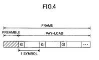
- the adaptive array system may receive an OFDM signal, a frame of which includes a preamble and a following payload as shown in Fig. 4.
- the preamble contains a signal pattern known to both a transmitter and a receiver.
- the payload comprises a plurality of symbols, each having a guard interval and following effective symbols.
- a digital signal contained in one symbol in the payload is outputted from the analog-to-digital converter 104, passes through the serial-parallel converter 114 and is Fast Fourier transformed by the Fast Fourier transformer 116. In this way, signal components are obtained with respect to all the 64 sub-carriers.
- a signal component for a virtual sub-carrier is extracted.
- a signal component U ⁇ m (n) for the sub-carrier f 0 corresponding to a DC component is extracted.
- a parameter n means a renewal step number of the weighting coefficients, and equals to 1 (first step) at present.
- a value m is an identification number of the antenna elements, and equals to zero at present.
- the value of the signal component U ⁇ m (n) is a reference value for perturbation calculations explained below.
- the signal component for the sub-carrier f 0 corresponding to a DC component
- other signal components for higher frequencies f 27 to f 31 and lower frequencies f -27 to f -32 can be extracted.
- this embodiment extracts the signal component from the sub-carrier f 0 corresponding to a DC component for simplicity.
- the signal components extracted from sub-carriers are represented by amplitude levels or power levels.
- the antenna element identification number m is increased by one, and becomes one at present, which means the first antenna element among the M antenna elements to be controlled.
- a weighting coefficient (or a controlling signal for setting the weighting coefficient) x m of the mth antenna element is given a minimal variation ⁇ x.
- ⁇ x ⁇ 1 + ⁇ x. Accordingly the directivity of the array antenna is changed.
- the weighting coefficient x m is changed by the first adjuster 124 in the adjuster 122.
- the array antenna with the changed directivity receives a signal contained in the next symbol.
- the received signal is Fast Fourier transformed by the Fast Fourier transformer 116, and signal components for all the sub-carriers are outputted.
- a first component of a gradient vector of the sub-carrier signal component U ⁇ is calculated. That is, based on the sub-carrier signal components before and after the minimal changes in the weighting coefficients, components of the gradient vector are calculated.
- Each component of the gradient vector ⁇ U ⁇ is calculated by the gradient calculator 120.
- the minimally changed weighting coefficient x m is changed back to the original value. Accordingly the directivity of the array antenna is returned back to the original one.
- step 326 it is determined whether the weighting coefficients are minimally changed and M components of the gradient vector are calculated for all the M antenna elements. At present, the answer is NO, and the process goes back to step 312. Then a weighting coefficient of the next antenna element is minimally changed, the sub-carrier signal component of the next symbol is measured, a component of the gradient vector is calculated, and then the minimally changed weighting coefficient is changed back to the original value. Similar procedures are repeated.
- the weighting coefficients are changed by the second adjuster 126.
- step 330 the renewal step number n is increased by one.
- step 332 it is determined whether the weighting coefficients have been renewed a predetermined number of times N. If not, the process goes back to step 306. If so, the process ends.
- the signal components U ⁇ are scalar variables depending on M weighting coefficients (x 1 , x 2 , ..., x M ).
- the gradient vector ⁇ U ⁇ means the direction which gives the sharpest change in the signal components of the virtual sub-carrier on a curved surface represented by the sub-carrier signal components U ⁇ that are multiple variable scalar functions. Therefore, going along the gradient vector ⁇ U ⁇ results in reaching the minimum value of the virtual sub-carrier signal component the fastest.
- the weighting coefficients give the minimum value of the virtual sub-carrier signal component, a desired wave can be received well and an undesired wave (interference wave) can be suppressed.
- the Fourier transformation of received signals and extraction of the sub-carrier signal components are carried out on a symbol by symbol basis. Accordingly, at least one symbol length period is required, from the start (step 302) of the process to the minimal change in the first antenna element weighting coefficient (step 312, 314). Andan M symbol length period is required until all the M antenna elements weighting coefficients are minimally changed to calculate all the M components of the gradient vector. Therefore, at least an M+1 symbol length period is needed for renewing the weighting coefficients one time.
- the virtual sub-carrier is not used for actual data transmission, therefore signal components in the preamble and payload of OFDM signal are zero ideally.
- the weighting coefficients can be renewed within merely an M+1 symbol length period.
- the array antenna should have good following-up characteristics responding the minimal change in the weighting coefficients.
- a known signal contained in the preamble can be utilized for calculating perturbations and renewing weighting coefficients. For example, if a sub-carrier signal component is extracted whenever the preamble is received, a long time of an M+1 frame is required for renewing the weighting coefficients one time. However, in this case, a gradient vector can be calculated based on the sub-carrier signal component for the same and already known signals contained in the preamble, and therefore high accuracy is obtained.
- the sub-carrier signal component in the first embodiment is one for the sub-carrier f 0 corresponding to a DC component. It is possible to utilize other signal components for other sub-carriers (such as higher frequencies f27 to f 31 , or lower frequencies f-27 to f -32 ). For example, if an unused virtual sub-carrier near to a sub-carrier used for the actual data transmission is utilized, it is advantageous in finding a Doppler shift effect. If a received signal is shifted to higher frequency due to the Doppler shift, data transmitted with a sub-carrier f 26 in a transmitter are received as a signal component on a different sub-carrier f 27 in a receiver.
- the signal component on the unused sub-carrier f 27 becomes suddenly large. If the sub-carrier f 27 signal component is monitored in the receiver, the Doppler shift influence can be detected immediately. The same is true in the lower frequency side. Accordingly it is desirable to utilize a virtual sub-carrier adjacent to a sub-carrier actually used for calculating perturbations, especially from the viewpoint of the Doppler shift effect.
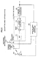
- Fig. 5 shows a block diagram of an adaptive array antenna system 500 according to another embodiment of the present invention.
- the adaptive array antenna system 500 comprises one powered antenna element 508 and a plurality of unpowered antenna elements 510.
- Each of the unpowered antenna elements 510 is connected to the earth potential via reactance element 511.
- the powered antenna element 508 is connected to a band-pass limitation filter 514.
- An output of the band-pass limitation filter 514 is connected to a first input of a mixer 516.
- An output of the mixed 516 is connected through an offset compensator 518 to an analog-to-digital converter 504.
- the offset compensator 518 compensates carrier frequency offset between a transmitter and a receiver.
- a compensation signal outputted from the offset compensator 518 is connected to a second input of the mixer 516.
- the band-pass limitation filter 514, the mixer 516 and the offset compensator 518 forms a front end device 512.
- An output of the analog-to-digital converter 504 is connected to an adaptive array antenna controller 506, which continuously controls a bias voltage to each reactance element 511.
- the adaptive array antenna controller 506 has the same structure as the adaptive array antenna controller 106 shown in Fig. 1.
- the powered antenna element 508 receives data transmission signals utilizing multiple carriers (sub-carriers) such as OFDM signals.
- Local oscillators used in a transmitter and a corresponding receiver should have the same oscillating frequency. However, due to device variation or age deterioration, their oscillating frequencies are sometimes offset. When such frequency offset becomes large, it becomes difficult to accurately suppress a virtual sub-carrier signal component. According to this embodiment, when converting a received signal, it is possible to adjust the frequency offset between the transmitter and the receiver to avoid frequency offset influence. Instead of adjusting the oscillating frequency, it is possible to carefully and adaptively select the sub-carrier in consideration of the frequency offset amount.
- a signal component transmitted with a sub-carrier f 26 may be received at the sub-carrier f 27 in a receiver.
- the oscillating frequency adjusting method adjusts the local oscillation frequency so as to receive the signal component at f26 in the receiver.
- a sub-carrier selection method makes the system suppress a sub-carrier f 28 signal component. In any event, the frequency offset between the transmitter and receiver should be considered when suppressing the virtual sub-carrier signal component.
- Fig. 6 shows a block diagram of an adaptive array antenna system 600 according to a further embodiment of the present invention.
- the adaptive array antenna system 600 comprises a first array antenna system 601, a second array antenna system 603 and a combining device 614 for combining outputs from both the first and second array antenna systems 601 and 603.
- the first and second array antenna systems 601 and 603 have the same structure and form diversity branches.
- Each of the first and second array antenna systems 601 and 603 has one powered antenna element 608 and a plurality of unpowered antenna elements 610.
- Each of the unpowered antenna elements 610 is connected to the earth potential via reactance element 611.
- the powered antenna element 608 is connected to a front end device 612 that performs band-pass limitation and frequency conversion and others.
- An output of the front end device 612 is connected to an analog-to-digital converter 604.
- An output of the analog-to-digital converter 604 is connected to an adaptive array antenna controller 606 that adaptively controls a weighting coefficient of each antenna element 610.
- the outputs from first and second analog-to-digital converters 604 are adjusted in phase and amplitude, respectively, by a weight adjuster 616 or 618, and then input to the combining device 614. In this way, the reception characteristics can be improved.
- weighting coefficients are adjusted so as to minimize a virtual sub-carrier signal component to control the directivity of each antenna.
- the combination device 614 combines the signals from both branches. According to this embodiment, it is possible to consider a virtual sub-carrier signal component when diversity combining. For example, a branch in which a virtual sub-carrier signal component is small can be selected or combined with one of large weight, to recover transmitted signals based on fewer interference signals.
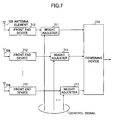
- Fig. 7 shows another array antenna structure that can be utilized for the present invention.
- This structure forms an RF processing system (of a phased array system).
- each of a plurality of antenna elements 708 is equipped with a front end device 612 performing a band-pass limitation and frequency conversion and others.
- An output of each front end device 712 is provided with a weight adjuster 711 for adjusting an amplitude and phase of a received signal.
- An output of each weight adjuster 711 is input to a combining device 714, from where a weighted and combined analog signal is outputted.
- This analog signal is inputted to a following analog-to-digital converter 104.
- the amplitude and phase adjustment in the weight adjuster 711 is performed based on control signals from the adaptive array antenna controller 106.
- the weighted and combined analog signal is converted by one analog-to-digital converter to form a signal supplied to a digital processing part (following the demodulation circuit and adaptive array antenna controller), and therefore advantages are gained from the viewpoints of power consumption, circuit size and cost.
- the RF processing type system shown in Fig. 7 can adjust amplitude and phase independently, and therefore the largest ratio combination is possible in the combination device 714, and it is advantageous in performing highly accurate control, compared with the Fig. 1 system.
- the spatial processing system shown in Fig. 1, controls reactance elements only and is advantageous in constructing a simple system, compared with the Fig. 7 system.
- the signal component for each sub-carrier is extracted, a virtual sub-carrier signal component is measured, and weighting coefficients of antenna elements are adaptively controlled so as to suppress the virtual sub-carrier signal component. Therefore, it is possible to suppress an interference component contained in a received signal while reducing consumption of power.
- any virtual sub-carrier signal component can be utilized, and therefore it is possible to suppress any interference signal independent from interference causes. For example, it is possible to suppress not only a delayed signal coming over an internal guard, and an interference signal due to the Doppler Effect, but also other interference signals generated by other communication systems.
- an array antenna 102 is adjusted to be non-directional, a received signal is Fourier transformed (step 308), and a virtual sub-carrier signal component is extracted (step 310). Therefore, it is possible to accurately detect the strength and direction of interference signals, and to effectively suppress interference components mingling with received signals by directing the antenna beam to a desired wave or directing the null to an undesired wave.
- weighting coefficients For example, there is a tendency for weighting coefficients to be converged into one value to provide a stronger directional antenna pattern, as the renewal step number increases.
- weighting coefficient variation between before and after renewal is excessively large, there is a high probability that a desired wave direction or an undesired wave direction will be changed due to the change in communication environment. Accordingly, when the weighting coefficient variation is larger than a predetermined value, it is advantageous to assume communication environmental changes and to adjust the array antenna to be non-directional.
- the communication environment changes, the direction or time delay of a desired or undesired wave is changed, and the virtual sub-carrier signal components may also be changed.
- the virtual sub-carrier signal component variation is larger than a predetermined value, it is advantageous to assume communication environmental changes and to adjust the array antenna to be non-directional.
Landscapes
- Engineering & Computer Science (AREA)
- Computer Networks & Wireless Communication (AREA)
- Signal Processing (AREA)
- Radio Transmission System (AREA)
- Variable-Direction Aerials And Aerial Arrays (AREA)
Applications Claiming Priority (2)
| Application Number | Priority Date | Filing Date | Title |
|---|---|---|---|
| JP2002380639A JP4154229B2 (ja) | 2002-12-27 | 2002-12-27 | 適応アレーアンテナ制御装置 |
| JP2002380639 | 2002-12-27 |
Publications (3)
| Publication Number | Publication Date |
|---|---|
| EP1434367A2 true EP1434367A2 (de) | 2004-06-30 |
| EP1434367A3 EP1434367A3 (de) | 2005-02-02 |
| EP1434367B1 EP1434367B1 (de) | 2008-03-12 |
Family
ID=32463640
Family Applications (1)
| Application Number | Title | Priority Date | Filing Date |
|---|---|---|---|
| EP03029674A Expired - Fee Related EP1434367B1 (de) | 2002-12-27 | 2003-12-23 | Vorrichtung zum adaptiven Steuern einer Gruppenantenne |
Country Status (4)
| Country | Link |
|---|---|
| US (1) | US20040135723A1 (de) |
| EP (1) | EP1434367B1 (de) |
| JP (1) | JP4154229B2 (de) |
| DE (1) | DE60319663T2 (de) |
Cited By (1)
| Publication number | Priority date | Publication date | Assignee | Title |
|---|---|---|---|---|
| WO2006016409A1 (ja) | 2004-08-12 | 2006-02-16 | Fujitsu Limited | 受信機、送信装置及び受信方法 |
Families Citing this family (13)
| Publication number | Priority date | Publication date | Assignee | Title |
|---|---|---|---|---|
| CN100499400C (zh) * | 2002-02-28 | 2009-06-10 | 三洋电机株式会社 | 无线装置、无线装置的校准系统、校准方法及校准程序 |
| JP2005321403A (ja) * | 2004-05-10 | 2005-11-17 | Ibeo Automobile Sensor Gmbh | 距離測定のための方法及び装置 |
| EP1792426A4 (de) * | 2004-09-23 | 2009-04-01 | Univ California | Architektur und verfahren für mehrfache unterträgerauswahldiversität für drahtloses ofdm |
| CN102868510B (zh) | 2004-10-29 | 2016-04-20 | 夏普株式会社 | 通信方法和无线发射机 |
| EP2555464B1 (de) | 2005-01-18 | 2019-03-06 | Sharp Kabushiki Kaisha | Vorrichtung zur Drahtlosen Kommunikation und Verfahren zur Drahtlosen Kommunikation |
| US8233554B2 (en) * | 2010-03-29 | 2012-07-31 | Eices Research, Inc. | Increased capacity communications for OFDM-based wireless communications systems/methods/devices |
| JP2007228348A (ja) * | 2006-02-24 | 2007-09-06 | Hitachi Kokusai Electric Inc | ダイバーシティ受信装置 |
| JP4732239B2 (ja) * | 2006-05-29 | 2011-07-27 | 京セラ株式会社 | 無線基地局及び無線基地局の制御方法 |
| US9565001B2 (en) * | 2007-06-01 | 2017-02-07 | Texas Instruments Incorporated | Guard subcarrier placement in an OFDM symbol used for synchronization |
| US8831684B2 (en) * | 2010-11-22 | 2014-09-09 | Kathrein-Werke Kg | Base transceiver station with radiation beam steering and active antenna |
| TWI661611B (zh) * | 2017-09-29 | 2019-06-01 | Arcadyan Technology Corporation | 應用於被動式Wi-Fi裝置的智慧天線及其控制方法 |
| US11031688B2 (en) | 2017-11-03 | 2021-06-08 | Dell Products, Lp | System and method for operating an antenna adaptation controller module |
| WO2019193377A1 (en) * | 2018-04-03 | 2019-10-10 | Nokia Technologies Oy | End-to-end learning in communication systems |
Citations (4)
| Publication number | Priority date | Publication date | Assignee | Title |
|---|---|---|---|---|
| US5307376A (en) * | 1991-01-17 | 1994-04-26 | France Telecom | Device for the coherent demodulation of time-frequency interlaced digital data, with estimation of the frequency response of the transmission channel and threshold, and corresponsing transmitter |
| US6035000A (en) * | 1996-04-19 | 2000-03-07 | Amati Communications Corporation | Mitigating radio frequency interference in multi-carrier transmission systems |
| EP1021019A1 (de) * | 1999-01-15 | 2000-07-19 | Sony International (Europe) GmbH | Verfahren zur quasi-differentiellen Modulation und Demodulation von multi-amplituden Signalen und OFDM System |
| US6327314B1 (en) * | 1998-04-01 | 2001-12-04 | At&T Corp. | Method and apparatus for channel estimation for multicarrier systems |
Family Cites Families (7)
| Publication number | Priority date | Publication date | Assignee | Title |
|---|---|---|---|---|
| US4236158A (en) * | 1979-03-22 | 1980-11-25 | Motorola, Inc. | Steepest descent controller for an adaptive antenna array |
| US4893350A (en) * | 1986-10-22 | 1990-01-09 | Kokusai Denshin Denwa Co., Ltd. | Interference cancellation system |
| US6195537B1 (en) * | 1997-09-25 | 2001-02-27 | Lucent Technologies, Inc. | Method and apparatus for strong signal suppression in multi-carrier signals |
| JP3675670B2 (ja) * | 1999-05-27 | 2005-07-27 | パイオニア株式会社 | 受信装置 |
| DE10032426B4 (de) * | 2000-07-04 | 2006-01-12 | Siemens Ag | Strahlformungsverfahren |
| US6369758B1 (en) * | 2000-11-01 | 2002-04-09 | Unique Broadband Systems, Inc. | Adaptive antenna array for mobile communication |
| JP3576099B2 (ja) * | 2000-12-22 | 2004-10-13 | 株式会社東芝 | スマートアンテナを用いた受信装置、スマートアンテナを用いた受信方法及びビーム形成回路 |
-
2002
- 2002-12-27 JP JP2002380639A patent/JP4154229B2/ja not_active Expired - Fee Related
-
2003
- 2003-12-23 EP EP03029674A patent/EP1434367B1/de not_active Expired - Fee Related
- 2003-12-23 DE DE60319663T patent/DE60319663T2/de not_active Expired - Lifetime
- 2003-12-23 US US10/746,217 patent/US20040135723A1/en not_active Abandoned
Patent Citations (4)
| Publication number | Priority date | Publication date | Assignee | Title |
|---|---|---|---|---|
| US5307376A (en) * | 1991-01-17 | 1994-04-26 | France Telecom | Device for the coherent demodulation of time-frequency interlaced digital data, with estimation of the frequency response of the transmission channel and threshold, and corresponsing transmitter |
| US6035000A (en) * | 1996-04-19 | 2000-03-07 | Amati Communications Corporation | Mitigating radio frequency interference in multi-carrier transmission systems |
| US6327314B1 (en) * | 1998-04-01 | 2001-12-04 | At&T Corp. | Method and apparatus for channel estimation for multicarrier systems |
| EP1021019A1 (de) * | 1999-01-15 | 2000-07-19 | Sony International (Europe) GmbH | Verfahren zur quasi-differentiellen Modulation und Demodulation von multi-amplituden Signalen und OFDM System |
Cited By (3)
| Publication number | Priority date | Publication date | Assignee | Title |
|---|---|---|---|---|
| WO2006016409A1 (ja) | 2004-08-12 | 2006-02-16 | Fujitsu Limited | 受信機、送信装置及び受信方法 |
| EP1777852A1 (de) * | 2004-08-12 | 2007-04-25 | Fujitsu Ltd. | Empfänger, sender und empfangsverfahren |
| EP1777852A4 (de) * | 2004-08-12 | 2011-12-07 | Fujitsu Ltd | Empfänger, sender und empfangsverfahren |
Also Published As
| Publication number | Publication date |
|---|---|
| DE60319663D1 (de) | 2008-04-24 |
| EP1434367B1 (de) | 2008-03-12 |
| DE60319663T2 (de) | 2009-04-02 |
| US20040135723A1 (en) | 2004-07-15 |
| JP4154229B2 (ja) | 2008-09-24 |
| JP2004214857A (ja) | 2004-07-29 |
| EP1434367A3 (de) | 2005-02-02 |
Similar Documents
| Publication | Publication Date | Title |
|---|---|---|
| EP2790331B1 (de) | MIMO-OFDM-Übertragungsvorrichtung und MIMO-OFDM-Übertragungsverfahren | |
| JP3718337B2 (ja) | 適応可変指向性アンテナ | |
| JP3782330B2 (ja) | Ofdm受信方法及びofdm受信装置 | |
| US9344178B2 (en) | Method of aiding uplink beamforming transmission | |
| EP1434367B1 (de) | Vorrichtung zum adaptiven Steuern einer Gruppenantenne | |
| US20140370823A1 (en) | Methods, processing device, computer programs, computer program products, and antenna apparatus for calibration of antenna apparatus | |
| EP1152548A1 (de) | Erhöhte Datenübertragungskapazität für Schnurloses Netzwerk mit hoher Datenrate | |
| JPH11205273A (ja) | Ofdmダイバーシチ受信装置 | |
| US7471729B2 (en) | Multicarrier transmission apparatus and multicarrier transmission method | |
| US20070188381A1 (en) | Receiver, transmission device and receiving method | |
| US7389086B2 (en) | Adaptive array antenna controller | |
| US7969860B2 (en) | Transmitter apparatus, receiver apparatus, transmitting method, receiving method, and program | |
| US7499727B2 (en) | Communications apparatus using adaptive antenna | |
| JP4080345B2 (ja) | 無線通信装置 | |
| JP4664961B2 (ja) | 適応アレーアンテナ・システム | |
| US6989721B2 (en) | Adaptive controller and adaptive control method that can adaptively control a plurality of variable high frequency devices at high speed | |
| JP3673244B2 (ja) | 無線装置 | |
| WO2014112366A1 (ja) | 無線通信装置、無線通信方法および無線通信システム |
Legal Events
| Date | Code | Title | Description |
|---|---|---|---|
| PUAI | Public reference made under article 153(3) epc to a published international application that has entered the european phase |
Free format text: ORIGINAL CODE: 0009012 |
|
| AK | Designated contracting states |
Kind code of ref document: A2 Designated state(s): AT BE BG CH CY CZ DE DK EE ES FI FR GB GR HU IE IT LI LU MC NL PT RO SE SI SK TR |
|
| AX | Request for extension of the european patent |
Extension state: AL LT LV MK |
|
| PUAL | Search report despatched |
Free format text: ORIGINAL CODE: 0009013 |
|
| AK | Designated contracting states |
Kind code of ref document: A3 Designated state(s): AT BE BG CH CY CZ DE DK EE ES FI FR GB GR HU IE IT LI LU MC NL PT RO SE SI SK TR |
|
| AX | Request for extension of the european patent |
Extension state: AL LT LV MK |
|
| RIC1 | Information provided on ipc code assigned before grant |
Ipc: 7H 04B 7/08 A Ipc: 7H 04L 27/26 B |
|
| 17P | Request for examination filed |
Effective date: 20050225 |
|
| AKX | Designation fees paid |
Designated state(s): DE FR GB |
|
| GRAP | Despatch of communication of intention to grant a patent |
Free format text: ORIGINAL CODE: EPIDOSNIGR1 |
|
| GRAS | Grant fee paid |
Free format text: ORIGINAL CODE: EPIDOSNIGR3 |
|
| GRAA | (expected) grant |
Free format text: ORIGINAL CODE: 0009210 |
|
| AK | Designated contracting states |
Kind code of ref document: B1 Designated state(s): DE FR GB |
|
| REG | Reference to a national code |
Ref country code: GB Ref legal event code: FG4D |
|
| REF | Corresponds to: |
Ref document number: 60319663 Country of ref document: DE Date of ref document: 20080424 Kind code of ref document: P |
|
| ET | Fr: translation filed | ||
| PLBE | No opposition filed within time limit |
Free format text: ORIGINAL CODE: 0009261 |
|
| STAA | Information on the status of an ep patent application or granted ep patent |
Free format text: STATUS: NO OPPOSITION FILED WITHIN TIME LIMIT |
|
| 26N | No opposition filed |
Effective date: 20081215 |
|
| PGFP | Annual fee paid to national office [announced via postgrant information from national office to epo] |
Ref country code: FR Payment date: 20091221 Year of fee payment: 7 Ref country code: GB Payment date: 20091223 Year of fee payment: 7 |
|
| PGFP | Annual fee paid to national office [announced via postgrant information from national office to epo] |
Ref country code: DE Payment date: 20091217 Year of fee payment: 7 |
|
| GBPC | Gb: european patent ceased through non-payment of renewal fee |
Effective date: 20101223 |
|
| REG | Reference to a national code |
Ref country code: FR Ref legal event code: ST Effective date: 20110831 |
|
| PG25 | Lapsed in a contracting state [announced via postgrant information from national office to epo] |
Ref country code: FR Free format text: LAPSE BECAUSE OF NON-PAYMENT OF DUE FEES Effective date: 20110103 |
|
| REG | Reference to a national code |
Ref country code: DE Ref legal event code: R119 Ref document number: 60319663 Country of ref document: DE Effective date: 20110701 |
|
| PG25 | Lapsed in a contracting state [announced via postgrant information from national office to epo] |
Ref country code: GB Free format text: LAPSE BECAUSE OF NON-PAYMENT OF DUE FEES Effective date: 20101223 Ref country code: DE Free format text: LAPSE BECAUSE OF NON-PAYMENT OF DUE FEES Effective date: 20110701 |