EP1434365B1 - Apparatus and method for adaptively modulating a signal by using a layered time-space detector in MIMO systems - Google Patents
Apparatus and method for adaptively modulating a signal by using a layered time-space detector in MIMO systems Download PDFInfo
- Publication number
- EP1434365B1 EP1434365B1 EP03258172.0A EP03258172A EP1434365B1 EP 1434365 B1 EP1434365 B1 EP 1434365B1 EP 03258172 A EP03258172 A EP 03258172A EP 1434365 B1 EP1434365 B1 EP 1434365B1
- Authority
- EP
- European Patent Office
- Prior art keywords
- channel gain
- equivalent channel
- layer
- nulling
- mimo
- Prior art date
- Legal status (The legal status is an assumption and is not a legal conclusion. Google has not performed a legal analysis and makes no representation as to the accuracy of the status listed.)
- Expired - Lifetime
Links
Images



Classifications
-
- H—ELECTRICITY
- H04—ELECTRIC COMMUNICATION TECHNIQUE
- H04B—TRANSMISSION
- H04B7/00—Radio transmission systems, i.e. using radiation field
- H04B7/02—Diversity systems; Multi-antenna system, i.e. transmission or reception using multiple antennas
- H04B7/04—Diversity systems; Multi-antenna system, i.e. transmission or reception using multiple antennas using two or more spaced independent antennas
- H04B7/08—Diversity systems; Multi-antenna system, i.e. transmission or reception using multiple antennas using two or more spaced independent antennas at the receiving station
- H04B7/0891—Space-time diversity
-
- H—ELECTRICITY
- H04—ELECTRIC COMMUNICATION TECHNIQUE
- H04B—TRANSMISSION
- H04B7/00—Radio transmission systems, i.e. using radiation field
- H04B7/02—Diversity systems; Multi-antenna system, i.e. transmission or reception using multiple antennas
- H04B7/04—Diversity systems; Multi-antenna system, i.e. transmission or reception using multiple antennas using two or more spaced independent antennas
- H04B7/0413—MIMO systems
- H04B7/0417—Feedback systems
-
- H—ELECTRICITY
- H04—ELECTRIC COMMUNICATION TECHNIQUE
- H04B—TRANSMISSION
- H04B7/00—Radio transmission systems, i.e. using radiation field
- H04B7/02—Diversity systems; Multi-antenna system, i.e. transmission or reception using multiple antennas
- H04B7/04—Diversity systems; Multi-antenna system, i.e. transmission or reception using multiple antennas using two or more spaced independent antennas
- H04B7/0413—MIMO systems
- H04B7/0426—Power distribution
-
- H—ELECTRICITY
- H04—ELECTRIC COMMUNICATION TECHNIQUE
- H04B—TRANSMISSION
- H04B7/00—Radio transmission systems, i.e. using radiation field
- H04B7/02—Diversity systems; Multi-antenna system, i.e. transmission or reception using multiple antennas
- H04B7/04—Diversity systems; Multi-antenna system, i.e. transmission or reception using multiple antennas using two or more spaced independent antennas
- H04B7/06—Diversity systems; Multi-antenna system, i.e. transmission or reception using multiple antennas using two or more spaced independent antennas at the transmitting station
- H04B7/0613—Diversity systems; Multi-antenna system, i.e. transmission or reception using multiple antennas using two or more spaced independent antennas at the transmitting station using simultaneous transmission
- H04B7/0615—Diversity systems; Multi-antenna system, i.e. transmission or reception using multiple antennas using two or more spaced independent antennas at the transmitting station using simultaneous transmission of weighted versions of same signal
- H04B7/0619—Diversity systems; Multi-antenna system, i.e. transmission or reception using multiple antennas using two or more spaced independent antennas at the transmitting station using simultaneous transmission of weighted versions of same signal using feedback from receiving side
- H04B7/0621—Feedback content
- H04B7/0626—Channel coefficients, e.g. channel state information [CSI]
-
- H—ELECTRICITY
- H04—ELECTRIC COMMUNICATION TECHNIQUE
- H04B—TRANSMISSION
- H04B7/00—Radio transmission systems, i.e. using radiation field
- H04B7/02—Diversity systems; Multi-antenna system, i.e. transmission or reception using multiple antennas
- H04B7/04—Diversity systems; Multi-antenna system, i.e. transmission or reception using multiple antennas using two or more spaced independent antennas
- H04B7/06—Diversity systems; Multi-antenna system, i.e. transmission or reception using multiple antennas using two or more spaced independent antennas at the transmitting station
- H04B7/0697—Diversity systems; Multi-antenna system, i.e. transmission or reception using multiple antennas using two or more spaced independent antennas at the transmitting station using spatial multiplexing
-
- H—ELECTRICITY
- H04—ELECTRIC COMMUNICATION TECHNIQUE
- H04L—TRANSMISSION OF DIGITAL INFORMATION, e.g. TELEGRAPHIC COMMUNICATION
- H04L1/00—Arrangements for detecting or preventing errors in the information received
- H04L1/0001—Systems modifying transmission characteristics according to link quality, e.g. power backoff
- H04L1/0002—Systems modifying transmission characteristics according to link quality, e.g. power backoff by adapting the transmission rate
- H04L1/0003—Systems modifying transmission characteristics according to link quality, e.g. power backoff by adapting the transmission rate by switching between different modulation schemes
-
- H—ELECTRICITY
- H04—ELECTRIC COMMUNICATION TECHNIQUE
- H04L—TRANSMISSION OF DIGITAL INFORMATION, e.g. TELEGRAPHIC COMMUNICATION
- H04L1/00—Arrangements for detecting or preventing errors in the information received
- H04L1/0001—Systems modifying transmission characteristics according to link quality, e.g. power backoff
- H04L1/0009—Systems modifying transmission characteristics according to link quality, e.g. power backoff by adapting the channel coding
-
- H—ELECTRICITY
- H04—ELECTRIC COMMUNICATION TECHNIQUE
- H04L—TRANSMISSION OF DIGITAL INFORMATION, e.g. TELEGRAPHIC COMMUNICATION
- H04L1/00—Arrangements for detecting or preventing errors in the information received
- H04L1/02—Arrangements for detecting or preventing errors in the information received by diversity reception
- H04L1/06—Arrangements for detecting or preventing errors in the information received by diversity reception using space diversity
- H04L1/0618—Space-time coding
- H04L1/0637—Properties of the code
- H04L1/0656—Cyclotomic systems, e.g. Bell Labs Layered Space-Time [BLAST]
-
- H—ELECTRICITY
- H04—ELECTRIC COMMUNICATION TECHNIQUE
- H04L—TRANSMISSION OF DIGITAL INFORMATION, e.g. TELEGRAPHIC COMMUNICATION
- H04L25/00—Baseband systems
- H04L25/02—Details ; arrangements for supplying electrical power along data transmission lines
- H04L25/0202—Channel estimation
- H04L25/0204—Channel estimation of multiple channels
-
- H—ELECTRICITY
- H04—ELECTRIC COMMUNICATION TECHNIQUE
- H04L—TRANSMISSION OF DIGITAL INFORMATION, e.g. TELEGRAPHIC COMMUNICATION
- H04L5/00—Arrangements affording multiple use of the transmission path
- H04L5/0001—Arrangements for dividing the transmission path
- H04L5/0028—Variable division
-
- H—ELECTRICITY
- H04—ELECTRIC COMMUNICATION TECHNIQUE
- H04L—TRANSMISSION OF DIGITAL INFORMATION, e.g. TELEGRAPHIC COMMUNICATION
- H04L5/00—Arrangements affording multiple use of the transmission path
- H04L5/003—Arrangements for allocating sub-channels of the transmission path
- H04L5/0044—Allocation of payload; Allocation of data channels, e.g. PDSCH or PUSCH
- H04L5/0046—Determination of the number of bits transmitted on different sub-channels
-
- H—ELECTRICITY
- H04—ELECTRIC COMMUNICATION TECHNIQUE
- H04L—TRANSMISSION OF DIGITAL INFORMATION, e.g. TELEGRAPHIC COMMUNICATION
- H04L5/00—Arrangements affording multiple use of the transmission path
- H04L5/003—Arrangements for allocating sub-channels of the transmission path
- H04L5/0058—Allocation criteria
- H04L5/006—Quality of the received signal, e.g. BER, SNR, water filling
-
- H—ELECTRICITY
- H04—ELECTRIC COMMUNICATION TECHNIQUE
- H04W—WIRELESS COMMUNICATION NETWORKS
- H04W52/00—Power management, e.g. Transmission Power Control [TPC] or power classes
- H04W52/04—Transmission power control [TPC]
- H04W52/38—TPC being performed in particular situations
- H04W52/42—TPC being performed in particular situations in systems with time, space, frequency or polarisation diversity
-
- H—ELECTRICITY
- H04—ELECTRIC COMMUNICATION TECHNIQUE
- H04L—TRANSMISSION OF DIGITAL INFORMATION, e.g. TELEGRAPHIC COMMUNICATION
- H04L5/00—Arrangements affording multiple use of the transmission path
- H04L5/0001—Arrangements for dividing the transmission path
- H04L5/0003—Two-dimensional division
- H04L5/0005—Time-frequency
- H04L5/0007—Time-frequency the frequencies being orthogonal, e.g. OFDM(A) or DMT
-
- H—ELECTRICITY
- H04—ELECTRIC COMMUNICATION TECHNIQUE
- H04L—TRANSMISSION OF DIGITAL INFORMATION, e.g. TELEGRAPHIC COMMUNICATION
- H04L5/00—Arrangements affording multiple use of the transmission path
- H04L5/0001—Arrangements for dividing the transmission path
- H04L5/0014—Three-dimensional division
- H04L5/0023—Time-frequency-space
Definitions
- the present invention relates to an apparatus for modulating/demodulating signal by using a layered time-space architecture detector in a multi-input multi-output (MIMO) system and a method thereof; and, more particularly, to the apparatus for modulating/demodulating signal by using a layered time-space architecture detector in a multi-input multi-output (MIMO) system in order to increase a system performance by deciding an equivalent channel gain, deciding the number of bits for transmitting through each antenna and deciding a transmission power by using the a greedy algorithm based on the decided equivalent channel gain.
- MIMO multi-input multi-output
- a multi-input multi-output (MIMO) system is a wireless communication system obtaining high frequency efficiency by transmitting each different data through a plurality of transmission antennas in an identical bandwidth.
- MIMO multi-input multi-output
- D-BLAST Diagonal Bell Laboratories Space Time
- V-BLAST Vertical-Bell Laboratories Space Time
- the V-BLAST system is a modified scheme of the D-BLAST system.
- a symbol corresponding to a layer having the largest equivalent channel gain is detected based on a MIMO channel matrix and new channel matrix is built by nulling a channel corresponding to the currently detected layer after canceling the effect of the detected symbol in the channel matrix H. And the above mentioned steps are repeated until all symbols are detected.
- a layer having largest equivalent channel gain is detected for the first time.
- the effect of the first symbol is eliminated because it is considered as interference and then the next symbol is detected. Therefore, a diversity gain can be obtained when the next symbol is detected and a performance is increased.
- V-BLAST system is in U.S. patent No. 6,317,466 B1 issued to G.J. Foschini , entitled "Wireless Communications System Having a Space-Time Architecture Employing Multi-Element antenna at both the Transmitter and Receiver" and also an adaptive modulation method is disclosed.
- G.J. Foschini a method for minimizing transmission power and changing modulation method commonly used for all antennas.
- a greedy algorithm for allocating power and the number of bits in multicarrier systems is introduced in an article by C. Y. Wong, entitled “Multiuser OFDM with adaptive sub-carrier, bit and power allocation", IEEE Journal on Selected Areas in Communication, Vol. 17, pp. 1747 ⁇ 1758, Oct., 1999 .
- the greedy algorithm is used for calculating a power and the number of bits of each subcarrier in order to transmit all information bits with the minimum transmission power while satisfying desired bit error rate under conditions such as single user orthogonal frequency division multiplexing (OFDM) is used, a frequency domain channel response corresponding to each subcarrier is known at the transmitter, the number of bits for transmitting at one OFDM symbol is predetermined and there is a desired bit error rate.
- OFDM orthogonal frequency division multiplexing
- a first method is introduced in an article by Ka-Wai Ng. et. al., entitled "A simplified bit allocation for V-BLAST based OFDM MIMO system in frequency selective fading channels” IEEE international conference on communication, pp. 411 ⁇ 415, 2002 .
- a second method is disclosed in an article by Ka-wai Ng et. al., entitled “Iterative bit & power allocation for V-BLAST based OFDM MIMO system in frequency selective fading channel", Proc. Wireless Communications and Networking Conference, 2002, pp. 271 ⁇ 275 .
- the first method calculates the equivalent channel gain based on an ordering method of the V-BLAST and decides the number of bits according to the greedy algorithm based on the calculated equivalent channel. It is also disclosed that a method of selecting a subcarrier and transmitting antenna in order to reduce the amount of information transmitted to the transmitter.
- the above mentioned approaches using the V-BLAST ordering method may obtain nearly same performance for all layers when fixed modulation method is used. However, the performance is degraded in a case of an adaptive modulation is used.
- the second method allocates a predetermined number of bits to all possible combinations of decision order for the optimal solution and selects the optimal order with minimum total transmission power. However, by reducing the number of combinations to be considered for finding the optimal solution, the performance is degraded.
- an object of the present invention to provided an apparatus for adaptively modulating /demodulating signals by using a layered time-space architecture detector in a multi-input multi-output (MIMO) system for improving a system performance by deciding an equivalent channel gain, deciding the number of bits for transmitting through each antenna and a transmission power by using a greedy algorithm based on the decided equivalent channel gain.
- MIMO multi-input multi-output
- an apparatus for adaptively modulating signal in a MIMO system having a layered space-time architecture based detector including: a bit and power allocation information calculator for deciding an equivalent channel gain in a reverse order of Vertical-Bell laboratories Space Time (V-BLAST) based on MIMO channel information feedbacked from a receiver and determining the number of bits and transmission power to be transmitted from each transmitting antenna by using the equivalent channel gain; and adaptive modulation means for modulating signal of each layer with corresponding modulation method based on the determined number of bits and transmitting power.
- V-BLAST Vertical-Bell laboratories Space Time
- an apparatus for adaptively demodulating signal in a MIMO system having a layered space-time architecture based detector including: MIMO channel estimation unit for estimating MIMO channel from a signal received through each receiving antenna; a bit and power allocation information calculator for determining an equivalent channel gain in reverse order of Vertical-Bell laboratories Space Time V-BLAST based on MIMO channel information from the MIMO channel estimation unit and determining the number of bits corresponding to each transmitting antenna by using the equivalent channel gain.
- apparatus for adaptively modulating and demodulating signals in MIMO system using multiple antennas at transmitter and receiver, the apparatus including: an adaptive modulation unit for adaptively modulating signals in order to transmit the modulated signal after determining an equivalent channel gain in a reverse order of a vertical-bell laboratories space time and determining the number of bits and transmitting power based on the determined equivalent channel gain; and adaptive demodulation unit for detecting and adaptively demodulating received signals through each receiving antenna in reverse order of V-BLAST.
- a method for adaptively modulating signals in a MIMO system using multiple antennas in a receiver and transmitter including the steps of: a) determining equivalent channel gain in a reverse order of V-BLAST at transmitter based on channel information feed backed from the receivers; and b) adaptively modulating signals by determining the number of bits and corresponding transmitting power to be transmitted through each layer (antenna) by using the equivalent channel gain in a greedy algorithm.
- a method for adaptively demodulating in MIMO systems including the steps of: a) estimating a channel from a signal received at each receiving antenna; b) deciding an equivalent channel gain in a reverse order of a vertical-bell laboratories space time (V-BLAST) based on the channel information; and c) detecting and adaptively demodulating the received signal using the adaptive modulation information for each layer.
- V-BLAST vertical-bell laboratories space time
- a computer readable recoding medium storing instructions for executing a method for an adaptive modulation, the method including the steps of: a) at a transmitter, deciding an equivalent channel gain in a reverse order of V-BLAST based on a feedback information from a receiver; and b) at the transmitter, deciding the number of bit transmitting through each layer (transmitting antenna) and transmitting power based on the equivalent channel gain computed at the step a).
- a computer readable recoding medium storing instructions for executing a method for an adaptive demodulation, the method including the steps of: a) estimating a channel from a signal received from each receiving antenna; b) deciding an equivalent channel gain in a reverse order of V-BLAST based on the channel information; and c) detecting and adaptively demodulating by deciding the number bits for each layer.
- h n is a channel gain of the n th subcarrier
- C n is the number of bit for transmitting with the subcarrier
- f ( C n ) is a is a transmission power for transmitting c bits with desired bit error rate (BER).
- Nc is the number of total subcarriers
- step 3 after completing step 2, each C n is determined and P n is calculated by using eq. 1.
- V-BLAST detection method data transmitted from a plurality of transmitting antenna is detected as one by one and the detected symbols are cancelled for reducing interference to other signals. The next symbol is detected after canceling the channel effect corresponding to the previously detected symbol. Therefore, the equivalent channel gain is varied according to an order of nulling.
- the present invention provides a method for achieving performance gain by adaptively modulating the signal with an equivalent channel gain obtained by the reverse order of conventional V-BLAST detection order.
- the V-BLAST detection method is explained at first.
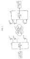
- Fig. 1 is diagram for illustrating a MIMO wireless communication system having a layered space-time architecture detector in accordance with a preferred embodiment of the present invention.
- M and N is the number of transmitting/receiving antennas and it is satisfied with a condition, N ⁇ M.
- H is N ⁇ M channel matrix, the element of the n th row and, a m th column, h n,m , is a flat fading channel gain between m th transmitting antenna and n th receiving antenna.
- I is NxN unit matrix.
- (H) l l th column of matrix H and w k T is a k th column of a pseudo-inverse matrix H + .
- a detection order is determined by considering a value of w k .
- is detected at first.
- x k is a result of decision of Z k .
- the Eqs. 6 to 9 are repeatedly executed for calculating a nulling vector by using new channel matrix H' and receiving signal vector y' until all signals are detected.
- the above mentioned steps are detection steps of conventional V-BLAST. Order of detection is determined according to the magnitude of norm of nulling vector.
- ⁇ k E x k 2 ⁇ 2 ⁇ w k ⁇ 2
- E ⁇ ⁇ is an expectation function and
- 2 is the equivalent channel gain. Therefore, a state of channel is better as
- the V-BLAST method for MIMO system using a fixed modulation/demodulation method detects a layer of best channel state at first and then detects a layer of worse channel state after eliminating interference of signals, which have already been detected in order to enhance performance of all layers.
- the adaptive modulation/demodulation method detects a layer of best channel state later and information of a layer of worse channel is not transmitted or less amount of information is transmitted in order to enhance the performance. Therefore, the detection order must to be reversed for enhancing the performance in accordance with the present invention.
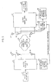
- Fig. 5 is a diagram showing an adaptive modulation/demodulation, and in the MIMO wireless communication system with V-BLAST type in accordance with a preferred embodiment of the present invention.
- a MIMO system having V-BLAST detector includes an adaptive modulation unit 52 and an adaptive demodulation unit 57 for modulating/demodulating signals with using different demodulation/modulation method and controlling transmission power of the signal.
- the demodulation unit 57 includes a V-BLAST type detection unit.
- a transmitting data 51 is data transmitted from a transmitter. If necessary, this date would be scrambled, channel coded, and interleaved.
- the adaptive modulation unit receives the channel information and controls transmitting power by modulating the data with different modulation methods according to each layer by using bit and power allocation information.
- a bit and power allocation information calculator 54 determines the number of bits and transmitting power to be transmitted to each transmitting antennas 53-1 to 53-M by using MIMO channel information feedbacked from a receivers and the greedy algorithm.
- signals transmitted from the M transmitting antennas 53-1 to 53-M are transmitted to N receiving antennas 56-1 to 56-N through frequency non-selective fading MIMO channel.
- the adaptive demodulation unit 57 demodulates the received signals by using channel estimation result from a MIMO channel estimator 58 and a bit allocate information from the bit allocation information calculator 59 in reverse order of V-BLAST. Finally, the demodulated signal is outputted.
- Fig. 2 is a view showing changing of equivalent channel gain according to an order of nulling in a layered space-time architecture in accordance with the present invention.
- the equivalent channel gain is changed according to an order of detection such as an order of V-BLAST, a random order and a reverse order of V-BLAST.
- an order of detection such as an order of V-BLAST, a random order and a reverse order of V-BLAST.
- a deviation of the equivalent channel gain is small and the sum of equivalent channel gain is small.
- the deviation and sum of the equivalent channel gain become larger.
- Fig. 3 is a flowchart for explaining the method for determining the equivalent channel gain in a reverse order of the V-BLAST detection method.
- An pseudo-inverse Matrix of channel matrix H + is calculated at step 32.
- all nulling vectors w k T , k ⁇ S, are calculated based on the Eq. 7 for calculating transmitting signal vector x.
- step 33 square root of a norm of nulling vector is calculated for determining a layer for nulling and k th layer having the largest value is selected at step 34.
- a column of the channel matrix corresponding to the selected k th layer is transformed to 0 vector and a value k is eliminated from the set S at step 35.
- the above mentioned steps are repeated M times with newly transformed set S and channel matrix H.
- an order of the selected layers becomes a detection order and an inverse of square root norm of the nulling vector for the selected layer becomes the equivalent channel gain. Furthermore, the number of bits transmitted at each layer (transmitting antenna) and corresponding transmitting power is calculated by using the calculated equivalent channel gain instead of subcarrier channel gain
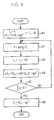
- Fig. 4 is a flowchart for explaining steps for determining the number of bits for transmitting of each transmitting antenna and corresponding transmitting power by using a equivalent channel gain according to greedy algorithm in accordance with a preferred embodiment of the present invention.
- the number of bits transmitted at each layer is initialized as '0'.
- ⁇ B is defined based on the Eq. 2 and a transmitting power is calculated for obtaining an additional bit value of ⁇ B with desired bit error rate at each layer by using the equivalent channel gain of each layer.
- a layer requiring the least transmitting power is selected and the value of ⁇ B is putted to the selected layer.
- the above mentioned steps are repeatedly performed until allocated total bit number is assigned.
- a transmitting power of each layer is calculated based on the Eq. 1.
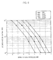
- Fig. 6 is a graph showing a performance of an adaptive modulation/demodulation method of a MIMO wireless communication system with V-BLAST type detector in accordance with a preferred embodiment of the present invention.
- the graph shows result of simulation for comparing performance of a conventional modulation/demodulation method and the modulation/demodulation method in accordance with the present invention.
- the number of transmitting and receiving antennas is 4 and a channel of each transmitting and receiving antenna is a complex Gaussian random variable with zero mean.
- a channel of each transmitting and receiving antenna is a complex Gaussian random variable with zero mean.
- more than 1000 statistic channels are generated.
- the number of information bits for transmitting in a predetermined time is set to 8 and QPSK and 16-QAM are used for modulation method.
- D ⁇ 0, 2, 4 ⁇ and therefore, ⁇ B is 2.
- SVD is a result of the conventional modulation/demodulation method
- BLAST is a result of using V-BLAST detection order introduced by Ka-wai Ng
- BLAST(random order) is a result of using random detection order
- BLAST(reverse) is a result of using reverse order of the V-BLAST detection order.
- the present invention has 0.7 bB performance gain and 1dB performance loss in comparison with Ka-wai Ng's method and the conventional modulation/demodulation method proposed by Raleigh.
- Fig. 7 is a diagram showing an adaptive modulation/demodulation apparatus of MIMO OFDM wireless communication system with V-BLAST type detector in accordance with a preferred embodiment of the present invention.
- an adaptive modulation MIMO system of the present invention can be expanded to the MIMO OFDM system. It is because a channel matrix H of the MIMO system can be replaced with a channel matrix in each subcarrier of MIMO-OFDM system. There are two methods implemented to the MIMO OFDM system.
- a first method is a method for implementing adaptive modulation method to all layers M and all subcarriers N c .
- an equivalent channel gain is independently calculated according to a layer of each transmitting antenna and subcarrier.
- the equivalent channel gain is calculated according to the method in Fig. 4 as much as the number of layers of the transmitting antenna times the number of subcarriers.
- N c ⁇ R number of information bits and transmitting power is allocated according to the greedy algorithm introduced in Fig. 4 by using the obtained N c ⁇ R number of equivalent channel gains.
- the number of information bits and corresponding transmitting power can be determined by using the equivalent channel gain obtained by the greedy algorithm in Fig. 4 for allocating data bits to total antennas and subcarriers.
- a value of M in Fig. 4 is a value of N becomes N c ⁇ M.
- the first method is very complicated to be implemented in real system because of large number of comparison and equivalent channel gain calculation in the greedy algorithm.
- a second method is a method for adaptively modulating signal per each subcarrier, independently. That is, if total data rate is predetermined in MIMO-OFDM system and the identical data bits are allocated to each sub carrier wave, the data bits must be allocated by obtaining the equivalent channel gain of each subcarrier. In this case, the number of the equivalent channel gain is M per each subcarrier.
- the data bits are allocated by using the greedy algorithm in Fig. 4 in M layers. Thus, Nc times of greedy algorithm are performed and the repetition number is decreased.
- the second method can be simply implemented comparing to the first method but its performance is decreased compared with the first method.
- the bit and power allocation information calculator 73 allocates the data bits by using the channel matrix H of each subcarrier delivered by the MIMO channel estimation unit 82 and the transmission power is also allocated to each transmitting antennas 76-1 to 76-M by using the equivalent channel gain of each subcarrier.
- the adaptive modulation unit based on V-BLAST type detector performs modulation operations using bits and power allocated to each transmitting antenna 76-1 to 76-M per each subcarrier.
- the V-BLAST detection and adaptive demodulation unit 81 demodulates a signal using bit allocation information.
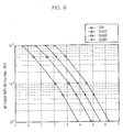
- Fig. 8 is a graph showing a result of a simulation of an adaptive modulation/demodulation method of MIMO OFDM wireless system with V-BLAST type detector in accordance with a preferred embodiment of the present invention.
- the simulation is progressed by using 4 transmitting and receiving antennas, 64 subcarriers and 16 cyclic prefixes are used for OFDM modulation.
- An exponentially decaying quasi-static fading channel having 8 taps is used.
- the method as mentioned above can be implemented as a program and can be stored in a computer readable recording medium such as CD-ROM, RAM, ROM, Floppy disk, Hard disk and optical magnetic disk.
- the present invention can improve performance above 0.7 ⁇ 1.4dB performance gain comparing to conventional modulation method with random and V-BLAST detection orders without increase of implementation complexity.
Landscapes
- Engineering & Computer Science (AREA)
- Signal Processing (AREA)
- Computer Networks & Wireless Communication (AREA)
- Quality & Reliability (AREA)
- Power Engineering (AREA)
- Radio Transmission System (AREA)
- Mobile Radio Communication Systems (AREA)
Description
- The present invention relates to an apparatus for modulating/demodulating signal by using a layered time-space architecture detector in a multi-input multi-output (MIMO) system and a method thereof; and, more particularly, to the apparatus for modulating/demodulating signal by using a layered time-space architecture detector in a multi-input multi-output (MIMO) system in order to increase a system performance by deciding an equivalent channel gain, deciding the number of bits for transmitting through each antenna and deciding a transmission power by using the a greedy algorithm based on the decided equivalent channel gain.
- Generally, a multi-input multi-output (MIMO) system is a wireless communication system obtaining high frequency efficiency by transmitting each different data through a plurality of transmission antennas in an identical bandwidth. There have been several detection methods for MIMO systems, such as a Diagonal Bell Laboratories Space Time (D-BLAST) system proposed in an article by G. J. Foschini, entitled "Layered Space-Time Architecture for Wireless Communication in a Fading Environment When using Multi-Element Antennas," Bell Labs Technical Journal, fall, pp. 41∼59, 1999 and a Vertical-Bell Laboratories Space Time (V-BLAST) system introduced in an article by P.W. Wolniansky et.al., entitled "V-Blast: An Architecture for Realizing Very High Data Rates Over the Rich-Scattering Wireless Channel." Proc. International Symposium Signals, Systems and Electronics, September, 1998.
- The V-BLAST system is a modified scheme of the D-BLAST system.
- Operations of detection in the V-BLAST system are explained in more detail hereinafter. At first, a symbol corresponding to a layer having the largest equivalent channel gain is detected based on a MIMO channel matrix and new channel matrix is built by nulling a channel corresponding to the currently detected layer after canceling the effect of the detected symbol in the channel matrix H. And the above mentioned steps are repeated until all symbols are detected. As a result of these operations, a layer having largest equivalent channel gain is detected for the first time. When the next symbol is detected, the effect of the first symbol is eliminated because it is considered as interference and then the next symbol is detected. Therefore, a diversity gain can be obtained when the next symbol is detected and a performance is increased.
- In a meantime, a structure of V-BLAST system is in
U.S. patent No. 6,317,466 B1 issued to G.J. Foschini , entitled "Wireless Communications System Having a Space-Time Architecture Employing Multi-Element antenna at both the Transmitter and Receiver" and also an adaptive modulation method is disclosed. But in the above mentioned patent by G.J. Foschini, a method for minimizing transmission power and changing modulation method commonly used for all antennas. - Furthermore, a greedy algorithm for allocating power and the number of bits in multicarrier systems is introduced in an article by C. Y. Wong, entitled "Multiuser OFDM with adaptive sub-carrier, bit and power allocation", IEEE Journal on Selected Areas in Communication, Vol. 17, pp. 1747∼1758, Oct., 1999. The greedy algorithm is used for calculating a power and the number of bits of each subcarrier in order to transmit all information bits with the minimum transmission power while satisfying desired bit error rate under conditions such as single user orthogonal frequency division multiplexing (OFDM) is used, a frequency domain channel response corresponding to each subcarrier is known at the transmitter, the number of bits for transmitting at one OFDM symbol is predetermined and there is a desired bit error rate.
- There are two methods implementing the MIMO-OFDM system with the adaptive modulation method. A first method is introduced in an article by Ka-Wai Ng. et. al., entitled "A simplified bit allocation for V-BLAST based OFDM MIMO system in frequency selective fading channels" IEEE international conference on communication, pp. 411∼415, 2002. A second method is disclosed in an article by Ka-wai Ng et. al., entitled "Iterative bit & power allocation for V-BLAST based OFDM MIMO system in frequency selective fading channel", Proc. Wireless Communications and Networking Conference, 2002, pp. 271∼275.
- The first method calculates the equivalent channel gain based on an ordering method of the V-BLAST and decides the number of bits according to the greedy algorithm based on the calculated equivalent channel. It is also disclosed that a method of selecting a subcarrier and transmitting antenna in order to reduce the amount of information transmitted to the transmitter. The above mentioned approaches using the V-BLAST ordering method may obtain nearly same performance for all layers when fixed modulation method is used. However, the performance is degraded in a case of an adaptive modulation is used.
- The second method allocates a predetermined number of bits to all possible combinations of decision order for the optimal solution and selects the optimal order with minimum total transmission power. However, by reducing the number of combinations to be considered for finding the optimal solution, the performance is degraded.
- The invention is defined in the independent claims.
- It is, therefore, an object of the present invention to provided an apparatus for adaptively modulating /demodulating signals by using a layered time-space architecture detector in a multi-input multi-output (MIMO) system for improving a system performance by deciding an equivalent channel gain, deciding the number of bits for transmitting through each antenna and a transmission power by using a greedy algorithm based on the decided equivalent channel gain.
- In accordance with an aspect of the present invention, there is provided an apparatus for adaptively modulating signal in a MIMO system having a layered space-time architecture based detector, the apparatus including: a bit and power allocation information calculator for deciding an equivalent channel gain in a reverse order of Vertical-Bell laboratories Space Time (V-BLAST) based on MIMO channel information feedbacked from a receiver and determining the number of bits and transmission power to be transmitted from each transmitting antenna by using the equivalent channel gain; and adaptive modulation means for modulating signal of each layer with corresponding modulation method based on the determined number of bits and transmitting power.
- In accordance with an aspect of the present invention, there is provided an apparatus for adaptively demodulating signal in a MIMO system having a layered space-time architecture based detector, the apparatus including: MIMO channel estimation unit for estimating MIMO channel from a signal received through each receiving antenna; a bit and power allocation information calculator for determining an equivalent channel gain in reverse order of Vertical-Bell laboratories Space Time V-BLAST based on MIMO channel information from the MIMO channel estimation unit and determining the number of bits corresponding to each transmitting antenna by using the equivalent channel gain.
- In accordance with an aspect of the present invention, there is provided apparatus for adaptively modulating and demodulating signals in MIMO system using multiple antennas at transmitter and receiver, the apparatus including: an adaptive modulation unit for adaptively modulating signals in order to transmit the modulated signal after determining an equivalent channel gain in a reverse order of a vertical-bell laboratories space time and determining the number of bits and transmitting power based on the determined equivalent channel gain; and adaptive demodulation unit for detecting and adaptively demodulating received signals through each receiving antenna in reverse order of V-BLAST.
- In accordance with an aspect of the present invention, there is provided a method for adaptively modulating signals in a MIMO system using multiple antennas in a receiver and transmitter, the method, including the steps of: a) determining equivalent channel gain in a reverse order of V-BLAST at transmitter based on channel information feed backed from the receivers; and b) adaptively modulating signals by determining the number of bits and corresponding transmitting power to be transmitted through each layer (antenna) by using the equivalent channel gain in a greedy algorithm.
- In accordance with an aspect of the present invention, there is provided a method for adaptively demodulating in MIMO systems, the method including the steps of: a) estimating a channel from a signal received at each receiving antenna; b) deciding an equivalent channel gain in a reverse order of a vertical-bell laboratories space time (V-BLAST) based on the channel information; and c) detecting and adaptively demodulating the received signal using the adaptive modulation information for each layer.
- In accordance with an aspect of the present invention, there is provided a computer readable recoding medium storing instructions for executing a method for an adaptive modulation, the method including the steps of: a) at a transmitter, deciding an equivalent channel gain in a reverse order of V-BLAST based on a feedback information from a receiver; and b) at the transmitter, deciding the number of bit transmitting through each layer (transmitting antenna) and transmitting power based on the equivalent channel gain computed at the step a).
- In accordance with an aspect of the present invention, there is provided a computer readable recoding medium storing instructions for executing a method for an adaptive demodulation, the method including the steps of: a) estimating a channel from a signal received from each receiving antenna; b) deciding an equivalent channel gain in a reverse order of V-BLAST based on the channel information; and c) detecting and adaptively demodulating by deciding the number bits for each layer.
- The above and other objects and features of the present invention will become apparent from the following description of the preferred embodiments given in conjunction with the accompanying drawings, in which:
-
Fig. 1 is a diagram for illustrating a MIMO wireless communication system having a layered space-time architecture detector in accordance with a preferred embodiment of the present invention; -
Fig. 2 is a view showing changing of equivalent channel gain according to the detection order in layered space-time architecture in accordance with the present invention; -
Fig. 3 is a flowchart for explaining a method for determining the equivalent channel gain in a reverse order of the V-BLAST detection method; -
Fig. 4 is a flowchart for explaining steps for determining the number of bits for transmitting of each transmitting antenna and corresponding transmitting power by using a equivalent channel gain according to greedy algorithm in accordance with a preferred embodiment; -
Fig. 5 is a diagram showing an apparatus for adaptively modulating/demodulating signal in the MIMO wireless communication system having layered space-time architecture in accordance with a preferred embodiment of the present invention; -
Fig. 6 is a graph showing a performance of a method for adaptively modulating/demodulating signals in a MIMO wireless communication system having V-BLAST type detector in accordance with a preferred embodiment of the present invention; -
Fig. 7 is a diagram showing an apparatus for adaptively modulating/demodulating signals in MIMO OFDM wireless communication system having V-BLAST type detector in accordance with a preferred embodiment of the present invention; and -
Fig. 8 is a graph showing a result of a simulation of a method for adaptively modulating/demodulating signal in MIMO OFDM wireless system having V-BLAST type detector in accordance with a preferred embodiment of the present invention. - Other objects and aspects of the invention will become apparent from the following description of the embodiments with reference to the accompanying drawings, which is set forth hereinafter.
- For helping to understand the present invention, a greedy algorithm used in an adaptive modulation/demodulation method in accordance with the present invention is explained at first.
- For explaining the greedy algorithm, an orthogonal frequency division multiplexing method is used as an example.
- At first, the transmission power of the nth subcarrier of, Pn, is given as:

- In the Eq. 1, hn is a channel gain of the nth subcarrier, Cn is the number of bit for transmitting with the subcarrier, and f(Cn ) is a is a transmission power for transmitting c bits with desired bit error rate (BER).
- In a meantime, if an entire bits for transmitting one of OFDM symbol is R, a bit allocation method for minimizing a sum of transmission power of entire subcarrier can be expressed as:


- In the Eq. 2, Nc is the number of total subcarriers, D represents a set of information bits per subcarrier determined by modulation/demodulation methods. For example, if a QPSK, 16-QAM, 64-QAM and so on can be selected for the modulation/demodulation methods, then D = {0, 2, 4, 6, 8, ...}. In here, 0 means that no information is sent in the corresponding subcarrier.
- The Eq. 2 can be solved by the greedy algorithm through following steps.
step 1: For all subcarriers, we define cn=0,
step 2: followingequations 


- In the Eqs. 4 and 5, ΔB is the difference of elements of set D e.g., D={0, 2, 4, 6, ...} . Therefore, ΔB =2.
- step 3: after completing
step 2, each Cn is determined and Pn is calculated by using eq. 1. - Finally, the number of bits allocated to each subcarrier, Cn, and the transmission power, Pn, is determined.
- In the V-BLAST detection method, data transmitted from a plurality of transmitting antenna is detected as one by one and the detected symbols are cancelled for reducing interference to other signals. The next symbol is detected after canceling the channel effect corresponding to the previously detected symbol. Therefore, the equivalent channel gain is varied according to an order of nulling. The present invention provides a method for achieving performance gain by adaptively modulating the signal with an equivalent channel gain obtained by the reverse order of conventional V-BLAST detection order. Hereinafter, the V-BLAST detection method is explained at first.
-
Fig. 1 is diagram for illustrating a MIMO wireless communication system having a layered space-time architecture detector in accordance with a preferred embodiment of the present invention. - Referring to
Fig. 1 , in the MIMO wireless communication system having a detector of V-BLAST structure, a signal vector transmitted from each transmission antenna 13-1, 13-2, ..., 13-M is defined as x=[x0, x1, ..., xM-1]T and a signal vector received to each receiving antenna 15-1, 15-2, ..., 15-N is defined as y= [y0, y1, ..., yN-1]T. M and N is the number of transmitting/receiving antennas and it is satisfied with a condition, N ≥ M. The received signal vector is expressed as:
- For detection of the transmitting signal vector x from the receiving signal vector y, the V-BLAST detection method is used. A nulling vector for kth layer (kth transmission antenna signal) is defined as:


- In the Eq. 8, k = {1, 2, ..., M}. After determining the signal by considering the decision statistic Zk , an interference of the previous detected signal is cancelled and the channel matrix H is updated. That is, new channel matrix H is generated by setting kth column of prior matrix H as '0'. New received signal vector y' is determined as:

- In the Eq. 9, xk is a result of decision of Zk. The Eqs. 6 to 9 are repeatedly executed for calculating a nulling vector by using new channel matrix H' and receiving signal vector y' until all signals are detected. The above mentioned steps are detection steps of conventional V-BLAST. Order of detection is determined according to the magnitude of norm of nulling vector.
- If the eq. 7 is used for calculating a signal - to - noise ratio of the decision statistics, ρk , which is calculated as:

- In the Eq. 10, E{ } is an expectation function and ||wk ||2 is the equivalent channel gain. Therefore, a state of channel is better as ||wk || is getting smaller. The V-BLAST method for MIMO system using a fixed modulation/demodulation method detects a layer of best channel state at first and then detects a layer of worse channel state after eliminating interference of signals, which have already been detected in order to enhance performance of all layers.
- However, the adaptive modulation/demodulation method detects a layer of best channel state later and information of a layer of worse channel is not transmitted or less amount of information is transmitted in order to enhance the performance. Therefore, the detection order must to be reversed for enhancing the performance in accordance with the present invention.
-
Fig. 5 is a diagram showing an adaptive modulation/demodulation, and in the MIMO wireless communication system with V-BLAST type in accordance with a preferred embodiment of the present invention. - Referring to
Fig. 5 , a MIMO system having V-BLAST detector includes anadaptive modulation unit 52 and anadaptive demodulation unit 57 for modulating/demodulating signals with using different demodulation/modulation method and controlling transmission power of the signal. Thedemodulation unit 57 includes a V-BLAST type detection unit. - Operations of the adaptive modulation/
demodulation units - A transmitting
data 51 is data transmitted from a transmitter. If necessary, this date would be scrambled, channel coded, and interleaved. The adaptive modulation unit receives the channel information and controls transmitting power by modulating the data with different modulation methods according to each layer by using bit and power allocation information. - When adaptively modulated signals are transmitted through M transmitting antennas 53-1 to 53-M, a bit and power
allocation information calculator 54 determines the number of bits and transmitting power to be transmitted to each transmitting antennas 53-1 to 53-M by using MIMO channel information feedbacked from a receivers and the greedy algorithm. - Through the above mentioned operations, signals transmitted from the M transmitting antennas 53-1 to 53-M are transmitted to N receiving antennas 56-1 to 56-N through frequency non-selective fading MIMO channel. And the
adaptive demodulation unit 57 demodulates the received signals by using channel estimation result from aMIMO channel estimator 58 and a bit allocate information from the bitallocation information calculator 59 in reverse order of V-BLAST. Finally, the demodulated signal is outputted. -
Fig. 2 is a view showing changing of equivalent channel gain according to an order of nulling in a layered space-time architecture in accordance with the present invention. - Referring to
Fig. 2 , although identical channel matrix is used, the equivalent channel gain is changed according to an order of detection such as an order of V-BLAST, a random order and a reverse order of V-BLAST. Thus, in case of detection according to the order of V-BLAST, a deviation of the equivalent channel gain is small and the sum of equivalent channel gain is small. And in case of detecting according to the reverse order of V-BLAST, the deviation and sum of the equivalent channel gain become larger. - A method for determining the equivalent channel gain in a reverse order of the V-BLAST detection method in accordance with a preferred embodiment of the present invention is explained in detail.
-
Fig. 3 is a flowchart for explaining the method for determining the equivalent channel gain in a reverse order of the V-BLAST detection method. - Referring to
Fig. 3 , atstep 31, an antenna index set is defined (S={1, 2, ..., M}) because of determining an order of detection for determining the equivalent channel gain. An pseudo-inverse Matrix of channel matrix H+ is calculated atstep 32. Atstep 33, all nulling vectors
- After the
step 33, square root of a norm of nulling vector is calculated for determining a layer for nulling and kth layer having the largest value is selected atstep 34. A column of the channel matrix corresponding to the selected kth layer is transformed to 0 vector and a value k is eliminated from the set S atstep 35. The above mentioned steps are repeated M times with newly transformed set S and channel matrix H. - As mentioned above, an order of the selected layers becomes a detection order and an inverse of square root norm of the nulling vector for the selected layer becomes the equivalent channel gain. Furthermore, the number of bits transmitted at each layer (transmitting antenna) and corresponding transmitting power is calculated by using the calculated equivalent channel gain instead of subcarrier channel gain ||hn || 2 in greedy algorithm.
-
Fig. 4 is a flowchart for explaining steps for determining the number of bits for transmitting of each transmitting antenna and corresponding transmitting power by using a equivalent channel gain according to greedy algorithm in accordance with a preferred embodiment of the present invention. - Referring to
Fig. 4 , atstep 41, the number of bits transmitted at each layer (each transmitting antenna) is initialized as '0'. ΔB is defined based on the Eq. 2 and a transmitting power is calculated for obtaining an additional bit value of ΔB with desired bit error rate at each layer by using the equivalent channel gain of each layer. Among the calculated layers, a layer requiring the least transmitting power is selected and the value of ΔB is putted to the selected layer. The above mentioned steps are repeatedly performed until allocated total bit number is assigned. After determining the number of bits transmitted through each layer, a transmitting power of each layer is calculated based on the Eq. 1. -
Fig. 6 is a graph showing a performance of an adaptive modulation/demodulation method of a MIMO wireless communication system with V-BLAST type detector in accordance with a preferred embodiment of the present invention. The graph shows result of simulation for comparing performance of a conventional modulation/demodulation method and the modulation/demodulation method in accordance with the present invention. - In the simulation, the number of transmitting and receiving antennas is 4 and a channel of each transmitting and receiving antenna is a complex Gaussian random variable with zero mean. For preventing to limit performance by influence of specific channel matrix, more than 1000 statistic channels are generated. The number of information bits for transmitting in a predetermined time is set to 8 and QPSK and 16-QAM are used for modulation method. Thus, D={0, 2, 4} and therefore, ΔB is 2.
- In the simulation, a system performance of a conventional modulation/demodulation method implemented by using greed algorithm with singular value decomposition (SVD), which is known as the optimal solution in the adaptive modulation MIMO system is used for a lower bound for comparison. The conventional modulation /demodulation method is introduced by G.G Raleigh et. al., in "spatiotemporal coding for wireless communication" at Proc. IEEE Globecom, Nov, 1996, pp. 1809-1814 and it has too complicated structure. Thus, it is impossible to be implemented to real system.
- Referring to the
Fig. 6 , SVD is a result of the conventional modulation/demodulation method, BLAST is a result of using V-BLAST detection order introduced by Ka-wai Ng and BLAST(random order) is a result of using random detection order. BLAST(reverse) is a result of using reverse order of the V-BLAST detection order. - As shown in
Fig. 6 , the present invention has 0.7 bB performance gain and 1dB performance loss in comparison with Ka-wai Ng's method and the conventional modulation/demodulation method proposed by Raleigh. -
Fig. 7 is a diagram showing an adaptive modulation/demodulation apparatus of MIMO OFDM wireless communication system with V-BLAST type detector in accordance with a preferred embodiment of the present invention. - Referring to
Fig. 7 , an adaptive modulation MIMO system of the present invention can be expanded to the MIMO OFDM system. It is because a channel matrix H of the MIMO system can be replaced with a channel matrix in each subcarrier of MIMO-OFDM system. There are two methods implemented to the MIMO OFDM system. - A first method is a method for implementing adaptive modulation method to all layers M and all subcarriers Nc. At first, an equivalent channel gain is independently calculated according to a layer of each transmitting antenna and subcarrier. The equivalent channel gain is calculated according to the method in
Fig. 4 as much as the number of layers of the transmitting antenna times the number of subcarriers. Finally, Nc×R number of information bits and transmitting power is allocated according to the greedy algorithm introduced inFig. 4 by using the obtained Nc×R number of equivalent channel gains. - Therefore, when total data rate is determined in the MIMO-OFDM transmitter, the number of information bits and corresponding transmitting power can be determined by using the equivalent channel gain obtained by the greedy algorithm in
Fig. 4 for allocating data bits to total antennas and subcarriers. Inhere, a value of M inFig. 4 is a value of N becomes Nc×M. However, the first method is very complicated to be implemented in real system because of large number of comparison and equivalent channel gain calculation in the greedy algorithm. - A second method is a method for adaptively modulating signal per each subcarrier, independently. That is, if total data rate is predetermined in MIMO-OFDM system and the identical data bits are allocated to each sub carrier wave, the data bits must be allocated by obtaining the equivalent channel gain of each subcarrier. In this case, the number of the equivalent channel gain is M per each subcarrier. The data bits are allocated by using the greedy algorithm in
Fig. 4 in M layers. Thus, Nc times of greedy algorithm are performed and the repetition number is decreased. The second method can be simply implemented comparing to the first method but its performance is decreased compared with the first method. - The bit and power
allocation information calculator 73 allocates the data bits by using the channel matrix H of each subcarrier delivered by the MIMOchannel estimation unit 82 and the transmission power is also allocated to each transmitting antennas 76-1 to 76-M by using the equivalent channel gain of each subcarrier. - The adaptive modulation unit based on V-BLAST type detector performs modulation operations using bits and power allocated to each transmitting antenna 76-1 to 76-M per each subcarrier.
- For demodulating a received signal at the MIMO OFDM system, bits and transmitting power is known. Therefore, in the
MIMO channel estimator 82 at a receiver, a channel matrix H of each subcarrier is estimated and performs operations for obtaining bits and power information using the greedy algorithm. The V-BLAST detection andadaptive demodulation unit 81 demodulates a signal using bit allocation information. -
Fig. 8 is a graph showing a result of a simulation of an adaptive modulation/demodulation method of MIMO OFDM wireless system with V-BLAST type detector in accordance with a preferred embodiment of the present invention. - Referring to
Fig. 8 , the simulation is progressed by using 4 transmitting and receiving antennas, 64 subcarriers and 16 cyclic prefixes are used for OFDM modulation. An exponentially decaying quasi-static fading channel having 8 taps is used. - The method as mentioned above can be implemented as a program and can be stored in a computer readable recording medium such as CD-ROM, RAM, ROM, Floppy disk, Hard disk and optical magnetic disk.
- The present invention can improve performance above 0.7 ∼ 1.4dB performance gain comparing to conventional modulation method with random and V-BLAST detection orders without increase of implementation complexity.
- While the present invention has been described with respect to certain preferred embodiments, it will be apparent to those skilled in the art that various changes and modifications may be made without departing from the scope of the invention as defined in the following claims.
Claims (14)
- An apparatus for adaptively modulating signal in a MIMO system having a layered space-time architecture based detector, the apparatus comprising:a bit and power allocation information calculator (54) for deciding an equivalent channel gain in a reverse order of Vertical-Bell laboratories Space Time (V-BLAST) based on MIMO channel information fed back from a receiver and determining the number of bits and transmission power to be transmitted to each transmitting antenna by using the equivalent channel gain, wherein the reverse order proceeds from an equivalent channel gain having the smallest value to an equivalent channel gain having the largest value, wherein the equivalent channel gain is an inverse of a norm of a nulling vector for a selected layer, and wherein the nulling vector is obtained from a pseudo-inverse of a channel matrix; andadaptive modulation means (52) for modulating signal of each layer with corresponding modulation method based on the determined number of bits, controlling the transmitting power and transmitting the adaptively modulated signal through each transmitting antenna.
- The apparatus as recited in claim 1, wherein a transmitter detects and modulates signals in a reverse order of a V-BLAST.
- The apparatus as recited in claim 1, wherein the bit and power allocation information calculation mean (54) determines an equivalent channel gain in the reverse order of V-BLAST and calculates the number of bit information and corresponding transmitting power at each layer by using the equivalent channel gain in a greedy algorithm instead of using channel gain.
- An apparatus for adaptively demodulating signal in a MIMO system having a layered space-time architecture based detector, the apparatus comprising:MIMO channel estimation means (58) for estimating MIMO channel from a signal received through each receiving antenna;a bit and power allocation information calculator (59) for determining an equivalent channel gain in reverse order of Vertical-Bell laboratories Space Time (V-BLAST) based on MIMO channel information from the MIMO channel estimation means and determining the number of bits to be transmitted from each transmitting antenna by using the equivalent channel gain, wherein the reverse order proceeds from an equivalent channel gain having the smallest value to an equivalent channel gain having the largest value, wherein the equivalent channel gain is an inverse of a norm of a nulling vector for a selected layer, and wherein the nulling vector is obtained from a pseudo-inverse of a channel matrix; andadaptive demodulation means (57) for demodulating signal of each layer with corresponding modulation method based on the determined number of bits and the MIMO channel information.
- An apparatus for adaptively modulating and demodulating signals in MIMO system using multiple antennas at transmitter and receivers, the apparatus comprising:an apparatus for adaptively modulating signal in a MIMO system according to claim 1; andan apparatus for adaptively demodulating signal in a MIMO system according to claim 4.
- The apparatus as recited in claim 5, wherein the apparatus has (the number of subcarriers) x (the number of transmission antennas) of equivalent channel gains and determines the number of bits and transmitting power to be transmitted through each transmission antennas in a MIMO-OFDM system having a layered space-time architecture detector.
- The apparatus as recited in claim 5, wherein the apparatus independently detects and demodulates signals per each subcarrier by determining the number of bits and transmitting power to be transmitted through each transmitting antenna per each subcarrier in a MIMO OFDM system having a layered space-time architecture detector.
- A method for adaptive modulating signals in a MIMO system using multiple antennas in a receiver and transmitter, the method comprising the steps of:a) determining equivalent channel gain in a reverse order of V-BLAST at transmitter based on information fed back from the receiver wherein the reverse order proceeds from an equivalent channel gain having the smallest value to an equivalent channel gain having the largest value, wherein the equivalent channel gain is an inverse of a norm of a nulling vector for a selected layer, and wherein the nulling vector is obtained from a pseudo-inverse of a channel matrix; andb) adaptively modulating signals by determining the number of bits and corresponding transmitting power to be transmitted through each layer by using the equivalent channel gain in a greedy algorithm.
- The method as recited in claim 8, wherein the transmitter detects and modulates signals in a reverse order of a V-BLAST.
- The method as recited in claim 9, wherein the step a) includes the steps of:a-1) initializing an antenna index set;a-2) nulling layers in an order of layer having a smallest equivalent channel gain and modifying the antenna index set or a channel matrix based on a result of nulling layers;a-3) repeatedly performing the step a-2) as many as the number of antennas; anda-4) deciding the equivalent channel gain of each antenna layer based on a result of the step a-3).
- The method as recited in the claim 10, wherein the step a-2) includes the steps of:a-2-1) computing (32) an pseudo-inverse matrix of channel matrix;a-2-2) computing (33) square root of norm of nulling vector for deciding a nulling layer;a-2-3) selecting (34) a layer having a biggest norm of nulling vectors among layers of computing results from the step a-2-2); anda-2-4) nulling (35) the selected layer and eliminating the selected layer from the antenna index set.
- The method as recited in claim 8, the step a) includes the steps of:a-a) initializing (31) an antenna index set;a-b) nulling layers in an order of layer having a smallest equivalent channel gain and modifying the antenna index set or a channel matrix based on a result of nulling layers;a-c) repeatedly performing the step a-b) as many as the number of antennas; anda-d) deciding the equivalent channel gain of each antenna layer based on a result of the step a-c).
- The method as recited in claim 8, wherein the step a), in a case there are preset data bits of the system and data bits allocated to each subcarrier arc identical, includes the steps of:a-I) initializing an antenna index set according to a subcarrier;a-II) nulling layers in an order of layer having a smallest equivalent channel gain and modifying the antenna index set or a channel matrix based on a result of nulling layers for the subcarrier;a-III) repeatedly performing the step a-II) as many as the number of antennas for the subcarrier; anda-IV) deciding the equivalent channel gain of each antenna layer based on a result of the step a-III).
- A method for adaptively demodulating in a multi input and multi output system, the method comprising the steps of:a) estimating a channel from a signal received at each receiving antenna;b) deciding an equivalent channel gain in a reverse order of a vertical-bell laboratories space time (V-BLAST) based on the channel information, wherein the reverse order proceeds from an equivalent channel gain having the smallest value to an equivalent channel gain having the largest value, wherein the equivalent channel gain is an inverse of a norm of a nulling vector for a selected layer, and wherein the nulling vector is obtained from a pseudo-inverse of the channel matrix; andc) detecting and adaptively demodulating by deciding the number of bits based on the equivalent channel gain.
Applications Claiming Priority (2)
| Application Number | Priority Date | Filing Date | Title |
|---|---|---|---|
| KR2002084478 | 2002-12-26 | ||
| KR1020020084478A KR100552669B1 (en) | 2002-12-26 | 2002-12-26 | Adaptive Modulation and Demodulation Apparatus and Its Method Applied to Multiple Input-Output Systems with Layered Space-Time Detectors |
Publications (3)
| Publication Number | Publication Date |
|---|---|
| EP1434365A2 EP1434365A2 (en) | 2004-06-30 |
| EP1434365A3 EP1434365A3 (en) | 2012-01-04 |
| EP1434365B1 true EP1434365B1 (en) | 2016-03-09 |
Family
ID=32464618
Family Applications (1)
| Application Number | Title | Priority Date | Filing Date |
|---|---|---|---|
| EP03258172.0A Expired - Lifetime EP1434365B1 (en) | 2002-12-26 | 2003-12-24 | Apparatus and method for adaptively modulating a signal by using a layered time-space detector in MIMO systems |
Country Status (4)
| Country | Link |
|---|---|
| US (2) | US7453947B2 (en) |
| EP (1) | EP1434365B1 (en) |
| JP (1) | JP4359495B2 (en) |
| KR (1) | KR100552669B1 (en) |
Families Citing this family (94)
| Publication number | Priority date | Publication date | Assignee | Title |
|---|---|---|---|---|
| US9130810B2 (en) | 2000-09-13 | 2015-09-08 | Qualcomm Incorporated | OFDM communications methods and apparatus |
| US7295509B2 (en) | 2000-09-13 | 2007-11-13 | Qualcomm, Incorporated | Signaling method in an OFDM multiple access system |
| KR100542090B1 (en) | 2002-12-16 | 2006-01-11 | 한국전자통신연구원 | Error control method, wireless access control frame design method, terminal registration method and recording medium in wireless communication system |
| KR100591890B1 (en) | 2003-04-01 | 2006-06-20 | 한국전자통신연구원 | Adaptive Transceiver Method and Apparatus in Multi Antenna Wireless Communication System |
| KR100557158B1 (en) * | 2003-11-12 | 2006-03-03 | 삼성전자주식회사 | Apparatus and Method for Subcarrier Allocation in Mobile Communication System Using Orthogonal Frequency Division Multiplexing |
| CN100349387C (en) * | 2004-04-13 | 2007-11-14 | 上海贝尔阿尔卡特股份有限公司 | Detecting method and device for vertical-bell laboratory layered space-time code |
| JP4604798B2 (en) * | 2004-05-10 | 2011-01-05 | ソニー株式会社 | Wireless communication system, wireless communication apparatus, wireless communication method, and computer program |
| US7596133B2 (en) | 2004-05-12 | 2009-09-29 | Samsung Electronics Co., Ltd | Apparatus and method for data transmission/reception using channel state information in wireless communication system |
| US9137822B2 (en) | 2004-07-21 | 2015-09-15 | Qualcomm Incorporated | Efficient signaling over access channel |
| US9148256B2 (en) | 2004-07-21 | 2015-09-29 | Qualcomm Incorporated | Performance based rank prediction for MIMO design |
| US7876848B2 (en) * | 2004-07-27 | 2011-01-25 | Samsung Electronics Co., Ltd. | Apparatus and method for transmitting a data stream in a wireless communication system with multiple antennas |
| ATE456232T1 (en) | 2004-08-12 | 2010-02-15 | Interdigital Tech Corp | METHOD AND APPARATUS FOR IMPLEMENTING SPACE-FREQUENCY BLOCK CODING IN A WIRELESS ORTHOGONAL FREQUENCY MULTIPLEX COMMUNICATIONS SYSTEM |
| KR101015708B1 (en) * | 2004-09-14 | 2011-02-24 | 삼성전자주식회사 | Adaptive Bit / Power Loading Scheme for Multicarrier Systems |
| US7577209B2 (en) | 2004-09-30 | 2009-08-18 | Intel Corporation | Deterministic spatial power allocation and bit loading for closed loop MIMO |
| KR100648472B1 (en) * | 2004-10-19 | 2006-11-28 | 삼성전자주식회사 | Transmission and reception apparatus and method for optimizing adaptive modulation and code performance in multiple transmit multiple receive antenna communication system |
| GB2419493A (en) * | 2004-10-19 | 2006-04-26 | Ict Ltd | Communications system utilising feed-back controlled multiple antennas |
| JPWO2006048934A1 (en) * | 2004-11-04 | 2008-05-22 | 松下電器産業株式会社 | Link adaptation system and method in MIMO-OFDM system |
| CN1783747A (en) * | 2004-12-01 | 2006-06-07 | 松下电器产业株式会社 | Detcting and bit distributing method and device in multiple antenna self adaption transmission |
| JP2006203782A (en) | 2005-01-24 | 2006-08-03 | Nec Corp | Radio communication system, receiving device, demodulation method, and program |
| CN100370719C (en) * | 2005-02-04 | 2008-02-20 | 西安交通大学 | Reception and detection method for vertical layered space-time system based on adaptive modulation |
| JP4888661B2 (en) | 2005-03-02 | 2012-02-29 | 日本電気株式会社 | Transmission control method for downlink packet communication and radio base station |
| US9246560B2 (en) | 2005-03-10 | 2016-01-26 | Qualcomm Incorporated | Systems and methods for beamforming and rate control in a multi-input multi-output communication systems |
| US9154211B2 (en) | 2005-03-11 | 2015-10-06 | Qualcomm Incorporated | Systems and methods for beamforming feedback in multi antenna communication systems |
| CN1835425A (en) * | 2005-03-16 | 2006-09-20 | 松下电器产业株式会社 | Self-adaptive modulation method based on multi-user precode |
| US8446892B2 (en) | 2005-03-16 | 2013-05-21 | Qualcomm Incorporated | Channel structures for a quasi-orthogonal multiple-access communication system |
| CN1835415A (en) * | 2005-03-16 | 2006-09-20 | 松下电器产业株式会社 | Low complexity bit used in radio communicating system and power allocation method and device |
| US9520972B2 (en) | 2005-03-17 | 2016-12-13 | Qualcomm Incorporated | Pilot signal transmission for an orthogonal frequency division wireless communication system |
| US9143305B2 (en) | 2005-03-17 | 2015-09-22 | Qualcomm Incorporated | Pilot signal transmission for an orthogonal frequency division wireless communication system |
| US9461859B2 (en) | 2005-03-17 | 2016-10-04 | Qualcomm Incorporated | Pilot signal transmission for an orthogonal frequency division wireless communication system |
| US9184870B2 (en) | 2005-04-01 | 2015-11-10 | Qualcomm Incorporated | Systems and methods for control channel signaling |
| US9408220B2 (en) | 2005-04-19 | 2016-08-02 | Qualcomm Incorporated | Channel quality reporting for adaptive sectorization |
| US9036538B2 (en) | 2005-04-19 | 2015-05-19 | Qualcomm Incorporated | Frequency hopping design for single carrier FDMA systems |
| US8565194B2 (en) | 2005-10-27 | 2013-10-22 | Qualcomm Incorporated | Puncturing signaling channel for a wireless communication system |
| US8611284B2 (en) | 2005-05-31 | 2013-12-17 | Qualcomm Incorporated | Use of supplemental assignments to decrement resources |
| US8879511B2 (en) | 2005-10-27 | 2014-11-04 | Qualcomm Incorporated | Assignment acknowledgement for a wireless communication system |
| US8462859B2 (en) | 2005-06-01 | 2013-06-11 | Qualcomm Incorporated | Sphere decoding apparatus |
| US7653122B2 (en) * | 2005-06-01 | 2010-01-26 | University Of Maryland | Method and system for power controlled effective allocation of sub-bands in ultra-wideband communication |
| US8599945B2 (en) | 2005-06-16 | 2013-12-03 | Qualcomm Incorporated | Robust rank prediction for a MIMO system |
| US9179319B2 (en) | 2005-06-16 | 2015-11-03 | Qualcomm Incorporated | Adaptive sectorization in cellular systems |
| JP4065283B2 (en) | 2005-07-06 | 2008-03-19 | 松下電器産業株式会社 | Sending method |
| US8885628B2 (en) | 2005-08-08 | 2014-11-11 | Qualcomm Incorporated | Code division multiplexing in a single-carrier frequency division multiple access system |
| US20070041457A1 (en) | 2005-08-22 | 2007-02-22 | Tamer Kadous | Method and apparatus for providing antenna diversity in a wireless communication system |
| US9209956B2 (en) | 2005-08-22 | 2015-12-08 | Qualcomm Incorporated | Segment sensitive scheduling |
| US8644292B2 (en) | 2005-08-24 | 2014-02-04 | Qualcomm Incorporated | Varied transmission time intervals for wireless communication system |
| US9136974B2 (en) | 2005-08-30 | 2015-09-15 | Qualcomm Incorporated | Precoding and SDMA support |
| CN100349388C (en) * | 2005-10-20 | 2007-11-14 | 上海交通大学 | Minimum emissive power adaptive modulation method of multiinput multioutput system |
| US8582509B2 (en) | 2005-10-27 | 2013-11-12 | Qualcomm Incorporated | Scalable frequency band operation in wireless communication systems |
| CN100525275C (en) * | 2005-10-27 | 2009-08-05 | 财团法人工业技术研究院 | MIMO-OFDM system and precoding and feedback method thereof |
| US9225488B2 (en) | 2005-10-27 | 2015-12-29 | Qualcomm Incorporated | Shared signaling channel |
| US9144060B2 (en) | 2005-10-27 | 2015-09-22 | Qualcomm Incorporated | Resource allocation for shared signaling channels |
| KR100652440B1 (en) * | 2005-10-27 | 2006-12-01 | 삼성전자주식회사 | Semiconductor package, stack package using the package, and method of forming the stack package |
| US8693405B2 (en) | 2005-10-27 | 2014-04-08 | Qualcomm Incorporated | SDMA resource management |
| US8045512B2 (en) | 2005-10-27 | 2011-10-25 | Qualcomm Incorporated | Scalable frequency band operation in wireless communication systems |
| US9210651B2 (en) | 2005-10-27 | 2015-12-08 | Qualcomm Incorporated | Method and apparatus for bootstraping information in a communication system |
| US8477684B2 (en) | 2005-10-27 | 2013-07-02 | Qualcomm Incorporated | Acknowledgement of control messages in a wireless communication system |
| US9088384B2 (en) | 2005-10-27 | 2015-07-21 | Qualcomm Incorporated | Pilot symbol transmission in wireless communication systems |
| US9172453B2 (en) | 2005-10-27 | 2015-10-27 | Qualcomm Incorporated | Method and apparatus for pre-coding frequency division duplexing system |
| US9225416B2 (en) | 2005-10-27 | 2015-12-29 | Qualcomm Incorporated | Varied signaling channels for a reverse link in a wireless communication system |
| CN100336329C (en) * | 2005-11-17 | 2007-09-05 | 上海交通大学 | Minimum transmitting power adaptive modulating method based on service quality requirement |
| US8582548B2 (en) | 2005-11-18 | 2013-11-12 | Qualcomm Incorporated | Frequency division multiple access schemes for wireless communication |
| US8831607B2 (en) | 2006-01-05 | 2014-09-09 | Qualcomm Incorporated | Reverse link other sector communication |
| JP4777440B2 (en) | 2006-02-01 | 2011-09-21 | エルジー エレクトロニクス インコーポレイティド | Data transmission / reception method using superposition modulation in wireless communication system |
| WO2007130963A1 (en) * | 2006-05-01 | 2007-11-15 | Intel Corporation | Providing cqi feedback with common code rate to a transmitter station |
| US7830977B2 (en) | 2006-05-01 | 2010-11-09 | Intel Corporation | Providing CQI feedback with common code rate to a transmitter station |
| KR100766322B1 (en) | 2006-06-01 | 2007-10-11 | 한국전자통신연구원 | Transmitter and Data Transmission Method in Multiple Input / Output System |
| KR100766065B1 (en) | 2006-06-01 | 2007-10-11 | 한국전자통신연구원 | Transmission vector demodulation method in multiple input / output system and receiver of system |
| IL177576A0 (en) * | 2006-08-20 | 2007-07-04 | Eci Telecom Ltd | Method for rate adaptation on a communication network |
| KR100808663B1 (en) * | 2006-12-06 | 2008-03-03 | 한국전자통신연구원 | Signal Detection Method and Receiver in Multiple Transceiver System |
| JP4658085B2 (en) * | 2007-03-16 | 2011-03-23 | 日本電信電話株式会社 | Adaptive antenna device and modulation method |
| KR100972297B1 (en) * | 2007-08-28 | 2010-07-23 | 한국전자통신연구원 | Adaptive Modulation Using Analog-to-Digital Converter with Variable Bit Resolution or Clock Frequency and Its Apparatus |
| CN101378280B (en) * | 2007-08-30 | 2012-07-18 | 中兴通讯股份有限公司 | Multi-input multi-output system based on antenna selection and signal processing method thereof |
| JP4583425B2 (en) * | 2007-09-11 | 2010-11-17 | パナソニック株式会社 | Transmitting apparatus and transmitting method |
| JP4583432B2 (en) * | 2007-11-13 | 2010-11-17 | パナソニック株式会社 | Modulator and modulation method |
| KR100943519B1 (en) * | 2007-11-22 | 2010-02-22 | 한국전자통신연구원 | Log likelihood ratio calculation method and transmission signal detection method |
| US8107428B2 (en) * | 2007-12-06 | 2012-01-31 | Ntt Docomo, Inc. | Method of ranging signal design and transmission for MIMO-OFDMA initial ranging process |
| KR100917862B1 (en) * | 2007-12-14 | 2009-09-18 | 한국전자통신연구원 | JR Decomposition Apparatus and Method in Multiple Input Multiple Output System |
| JP4583457B2 (en) * | 2008-01-16 | 2010-11-17 | パナソニック株式会社 | Modulation method and modulator |
| KR101505085B1 (en) * | 2008-03-27 | 2015-03-23 | 삼성전자주식회사 | Dispersion vector coding apparatus and method based on eigen-constant normalization in a multi-user multi-antenna system |
| CN101340419B (en) * | 2008-08-12 | 2012-03-07 | 中兴通讯股份有限公司 | Bit power distribution method for MIMO-OFDM system |
| CN102055566B (en) * | 2011-01-21 | 2015-05-13 | 复旦大学 | Dynamic MIMO (multiple input multiple output) detection algorithm and detector structure based on signal channel analysis |
| US8837612B2 (en) * | 2011-06-17 | 2014-09-16 | Microsoft Corporation | Multiple independent narrow channels in wireless networks |
| US8942659B2 (en) | 2011-09-08 | 2015-01-27 | Drexel University | Method for selecting state of a reconfigurable antenna in a communication system via machine learning |
| GB2514174B (en) * | 2013-05-17 | 2015-12-02 | Cambium Networks Ltd | Improvements to adaptive modulation |
| KR102176635B1 (en) | 2015-06-05 | 2020-11-09 | 삼성전자주식회사 | Apparatus and method for transmitting and receiving for control information in wireless communication system |
| CN105187355B (en) * | 2015-06-18 | 2018-12-18 | 电子科技大学 | A kind of day line options-power adaptive modulating method |
| US9553640B1 (en) * | 2015-12-22 | 2017-01-24 | Microsoft Technology Licensing, Llc | Using multi-feed antennas |
| CN107204825B (en) * | 2016-03-16 | 2019-07-12 | 华为技术有限公司 | Data sending method, data receiving method, sending end device and receiving end device |
| US10925005B2 (en) * | 2016-03-25 | 2021-02-16 | Apple Inc. | Uplink power control for 5G systems |
| CN106209187B (en) * | 2016-07-12 | 2019-11-12 | 重庆邮电大学 | An Adaptive Generalized Spatial Modulation Method Using Joint Optimization |
| CN109803309B (en) * | 2017-11-17 | 2021-06-29 | 华为技术有限公司 | Communication method and device |
| KR102098262B1 (en) * | 2018-06-27 | 2020-04-07 | 주식회사 쏠리드 | Crest factor reduction method based on signal modulation mode, and device using the same |
| KR102006919B1 (en) * | 2018-10-02 | 2019-08-02 | 주식회사 쏠리드 | Method for determining modulation mode of communication signal, communication node and communication system using the same |
| US11990926B2 (en) * | 2020-11-11 | 2024-05-21 | TalkingHeads Wireless, Inc. | Systems and related techniques for efficient operation of a cellular network |
| CN115102809B (en) * | 2022-05-07 | 2025-06-17 | 南京航空航天大学 | An adaptive modulation method for multi-cell massive MIMO system based on incomplete channel information |
Family Cites Families (5)
| Publication number | Priority date | Publication date | Assignee | Title |
|---|---|---|---|---|
| US4679227A (en) * | 1985-05-20 | 1987-07-07 | Telebit Corporation | Ensemble modem structure for imperfect transmission media |
| US6097771A (en) * | 1996-07-01 | 2000-08-01 | Lucent Technologies Inc. | Wireless communications system having a layered space-time architecture employing multi-element antennas |
| US6317466B1 (en) * | 1998-04-15 | 2001-11-13 | Lucent Technologies Inc. | Wireless communications system having a space-time architecture employing multi-element antennas at both the transmitter and receiver |
| EP1255369A1 (en) * | 2001-05-04 | 2002-11-06 | TELEFONAKTIEBOLAGET LM ERICSSON (publ) | Link adaptation for wireless MIMO transmission schemes |
| KR100648472B1 (en) * | 2004-10-19 | 2006-11-28 | 삼성전자주식회사 | Transmission and reception apparatus and method for optimizing adaptive modulation and code performance in multiple transmit multiple receive antenna communication system |
-
2002
- 2002-12-26 KR KR1020020084478A patent/KR100552669B1/en not_active Expired - Fee Related
-
2003
- 2003-12-16 US US10/737,398 patent/US7453947B2/en not_active Ceased
- 2003-12-22 JP JP2003425813A patent/JP4359495B2/en not_active Expired - Fee Related
- 2003-12-24 EP EP03258172.0A patent/EP1434365B1/en not_active Expired - Lifetime
-
2010
- 2010-11-18 US US12/949,425 patent/USRE44092E1/en not_active Expired - Fee Related
Also Published As
| Publication number | Publication date |
|---|---|
| US7453947B2 (en) | 2008-11-18 |
| JP2004215254A (en) | 2004-07-29 |
| EP1434365A3 (en) | 2012-01-04 |
| JP4359495B2 (en) | 2009-11-04 |
| EP1434365A2 (en) | 2004-06-30 |
| KR20040058440A (en) | 2004-07-05 |
| KR100552669B1 (en) | 2006-02-20 |
| US20040141566A1 (en) | 2004-07-22 |
| USRE44092E1 (en) | 2013-03-19 |
Similar Documents
| Publication | Publication Date | Title |
|---|---|---|
| US7453947B2 (en) | Apparatus and method for adaptively modulating signal by using layered time-space detector used in mimo system | |
| EP1570579B1 (en) | Rate adaptive transmission scheme for MIMO systems | |
| KR100955795B1 (en) | Wireless communication using multi-transmit multi-receive antenna arrays | |
| US8908743B2 (en) | Receiver with multi layer interference cancellation | |
| US6987819B2 (en) | Method and device for multiple input/multiple output transmit and receive weights for equal-rate data streams | |
| US7450532B2 (en) | Apparatus and method for transmitting data by selected eigenvector in closed loop MIMO mobile communication system | |
| EP1386438B1 (en) | Link adaption for wireless mimo transmission schemes | |
| US8774152B2 (en) | Method and apparatus for managing control channel in a mobile communication system using multiple antennas | |
| US6901122B2 (en) | Method and apparatus for restoring a soft decision component of a signal | |
| EP2237433A2 (en) | Successive interference cancellation receiver processing with selection diversity | |
| US20090175320A1 (en) | Method to Determine the Number of Data Streams to Be Used in a MIMO System | |
| US20050254461A1 (en) | Apparatus and method for data transmission/reception using channel state information in wireless communication system | |
| EP1750402B1 (en) | Spatial multiplexing detection apparatus and method in MIMO system | |
| KR100603765B1 (en) | Antenna Selection System and Method Using Multiple Input Multiple Output Technology | |
| EP2221990B1 (en) | Apparatus and method for supporting multiple-input multiple-output and beamforming simultaneously in wireless communication system | |
| Mitsuyamay et al. | Adaptive bit and power allocation algorithm for SVD-MIMO system with fixed transmission rate | |
| US20060182207A1 (en) | Hybrid STBC receiver | |
| Codreanu et al. | Compensation of channel state estimation errors in adaptive MIMO-OFDM systems | |
| Codreanu et al. | Adaptive MIMO-OFDM systems with channel state information at TX side | |
| Shi et al. | An iterative transmission power allocation scheme for MIMO-OFDM systems [cellular radio] | |
| Hwang et al. | Improvement of AMC-MIMO multiplexing systems with selection transmit diversity techniques | |
| Kim et al. | An adaptive MIMO transmission technique for LDPC coded OFDM cellular systems | |
| Jamel et al. | Performance Evaluation of Vertical Bell Labs Layered Space Time (Vblast) Algorithms For Mimo System | |
| Zhao et al. | Capacity bound of MIMO systems with MPSK modulation and superimposed pilots |
Legal Events
| Date | Code | Title | Description |
|---|---|---|---|
| PUAI | Public reference made under article 153(3) epc to a published international application that has entered the european phase |
Free format text: ORIGINAL CODE: 0009012 |
|
| AK | Designated contracting states |
Kind code of ref document: A2 Designated state(s): AT BE BG CH CY CZ DE DK EE ES FI FR GB GR HU IE IT LI LU MC NL PT RO SE SI SK TR |
|
| AX | Request for extension of the european patent |
Extension state: AL LT LV MK |
|
| RIN1 | Information on inventor provided before grant (corrected) |
Inventor name: YU, HEEJUNG Inventor name: JEON, TAEHYUN Inventor name: KIM, JOUNG-DOO Inventor name: CHOI, JIHOON Inventor name: AHN, JAE-YOUNG Inventor name: LEE, YONG-HOON Inventor name: KIM, INHYOUNG |
|
| PUAL | Search report despatched |
Free format text: ORIGINAL CODE: 0009013 |
|
| RIC1 | Information provided on ipc code assigned before grant |
Ipc: H04B 7/04 20060101ALI20111111BHEP Ipc: H04L 1/00 20060101ALI20111111BHEP Ipc: H04B 7/08 20060101ALI20111111BHEP Ipc: H04W 52/42 20090101ALI20111111BHEP Ipc: H04B 7/06 20060101AFI20111111BHEP Ipc: H04L 1/06 20060101ALI20111111BHEP |
|
| AK | Designated contracting states |
Kind code of ref document: A3 Designated state(s): AT BE BG CH CY CZ DE DK EE ES FI FR GB GR HU IE IT LI LU MC NL PT RO SE SI SK TR |
|
| AX | Request for extension of the european patent |
Extension state: AL LT LV MK |
|
| 17P | Request for examination filed |
Effective date: 20120704 |
|
| 17Q | First examination report despatched |
Effective date: 20120810 |
|
| AKX | Designation fees paid |
Designated state(s): AT BE BG CH CY CZ DE DK EE ES FI FR GB GR HU IE IT LI LU MC NL PT RO SE SI SK TR |
|
| AXX | Extension fees paid |
Extension state: MK Payment date: 20120704 |
|
| GRAP | Despatch of communication of intention to grant a patent |
Free format text: ORIGINAL CODE: EPIDOSNIGR1 |
|
| 111L | Licence recorded |
Designated state(s): AT BE BG CH CY CZ DE DK EE ES FI FR GB GR HU IE IT LU MC NL PT RO SE SI SK TR Free format text: EXCLUSIVE LICENSE Name of requester: INTELLECTUAL DISCOVERY CO., LTD., KR Effective date: 20150721 |
|
| INTG | Intention to grant announced |
Effective date: 20150824 |
|
| GRAS | Grant fee paid |
Free format text: ORIGINAL CODE: EPIDOSNIGR3 |
|
| GRAA | (expected) grant |
Free format text: ORIGINAL CODE: 0009210 |
|
| 111L | Licence recorded |
Designated state(s): AT BE BG CH CY CZ DE DK EE ES FI FR GB GR HU IE IT LU MC NL PT RO SE SI SK TR Free format text: EXCLUSIVE LICENSE Name of requester: INTELLECTUAL DISCOVERY CO., LTD., KR Effective date: 20150721 |
|
| AK | Designated contracting states |
Kind code of ref document: B1 Designated state(s): AT BE BG CH CY CZ DE DK EE ES FI FR GB GR HU IE IT LI LU MC NL PT RO SE SI SK TR |
|
| REG | Reference to a national code |
Ref country code: GB Ref legal event code: FG4D |
|
| REG | Reference to a national code |
Ref country code: AT Ref legal event code: REF Ref document number: 780159 Country of ref document: AT Kind code of ref document: T Effective date: 20160315 Ref country code: CH Ref legal event code: PK Free format text: ERGAENZUNG LIZENZEINTRAG: AUSSCHLIESSLICHE LIZENZ Ref country code: CH Ref legal event code: EP |
|
| REG | Reference to a national code |
Ref country code: IE Ref legal event code: FG4D |
|
| REG | Reference to a national code |
Ref country code: DE Ref legal event code: R096 Ref document number: 60348620 Country of ref document: DE |
|
| REG | Reference to a national code |
Ref country code: NL Ref legal event code: MP Effective date: 20160309 |
|
| PG25 | Lapsed in a contracting state [announced via postgrant information from national office to epo] |
Ref country code: GR Free format text: LAPSE BECAUSE OF FAILURE TO SUBMIT A TRANSLATION OF THE DESCRIPTION OR TO PAY THE FEE WITHIN THE PRESCRIBED TIME-LIMIT Effective date: 20160610 Ref country code: ES Free format text: LAPSE BECAUSE OF FAILURE TO SUBMIT A TRANSLATION OF THE DESCRIPTION OR TO PAY THE FEE WITHIN THE PRESCRIBED TIME-LIMIT Effective date: 20160309 Ref country code: FI Free format text: LAPSE BECAUSE OF FAILURE TO SUBMIT A TRANSLATION OF THE DESCRIPTION OR TO PAY THE FEE WITHIN THE PRESCRIBED TIME-LIMIT Effective date: 20160309 |
|
| REG | Reference to a national code |
Ref country code: AT Ref legal event code: MK05 Ref document number: 780159 Country of ref document: AT Kind code of ref document: T Effective date: 20160309 |
|
| PG25 | Lapsed in a contracting state [announced via postgrant information from national office to epo] |
Ref country code: SE Free format text: LAPSE BECAUSE OF FAILURE TO SUBMIT A TRANSLATION OF THE DESCRIPTION OR TO PAY THE FEE WITHIN THE PRESCRIBED TIME-LIMIT Effective date: 20160309 Ref country code: NL Free format text: LAPSE BECAUSE OF FAILURE TO SUBMIT A TRANSLATION OF THE DESCRIPTION OR TO PAY THE FEE WITHIN THE PRESCRIBED TIME-LIMIT Effective date: 20160309 |
|
| PG25 | Lapsed in a contracting state [announced via postgrant information from national office to epo] |
Ref country code: EE Free format text: LAPSE BECAUSE OF FAILURE TO SUBMIT A TRANSLATION OF THE DESCRIPTION OR TO PAY THE FEE WITHIN THE PRESCRIBED TIME-LIMIT Effective date: 20160309 |
|
| PG25 | Lapsed in a contracting state [announced via postgrant information from national office to epo] |
Ref country code: PT Free format text: LAPSE BECAUSE OF FAILURE TO SUBMIT A TRANSLATION OF THE DESCRIPTION OR TO PAY THE FEE WITHIN THE PRESCRIBED TIME-LIMIT Effective date: 20160711 Ref country code: CZ Free format text: LAPSE BECAUSE OF FAILURE TO SUBMIT A TRANSLATION OF THE DESCRIPTION OR TO PAY THE FEE WITHIN THE PRESCRIBED TIME-LIMIT Effective date: 20160309 Ref country code: RO Free format text: LAPSE BECAUSE OF FAILURE TO SUBMIT A TRANSLATION OF THE DESCRIPTION OR TO PAY THE FEE WITHIN THE PRESCRIBED TIME-LIMIT Effective date: 20160309 Ref country code: SK Free format text: LAPSE BECAUSE OF FAILURE TO SUBMIT A TRANSLATION OF THE DESCRIPTION OR TO PAY THE FEE WITHIN THE PRESCRIBED TIME-LIMIT Effective date: 20160309 Ref country code: AT Free format text: LAPSE BECAUSE OF FAILURE TO SUBMIT A TRANSLATION OF THE DESCRIPTION OR TO PAY THE FEE WITHIN THE PRESCRIBED TIME-LIMIT Effective date: 20160309 |
|
| REG | Reference to a national code |
Ref country code: DE Ref legal event code: R097 Ref document number: 60348620 Country of ref document: DE |
|
| PG25 | Lapsed in a contracting state [announced via postgrant information from national office to epo] |
Ref country code: IT Free format text: LAPSE BECAUSE OF FAILURE TO SUBMIT A TRANSLATION OF THE DESCRIPTION OR TO PAY THE FEE WITHIN THE PRESCRIBED TIME-LIMIT Effective date: 20160309 Ref country code: BE Free format text: LAPSE BECAUSE OF FAILURE TO SUBMIT A TRANSLATION OF THE DESCRIPTION OR TO PAY THE FEE WITHIN THE PRESCRIBED TIME-LIMIT Effective date: 20160309 |
|
| PLBE | No opposition filed within time limit |
Free format text: ORIGINAL CODE: 0009261 |
|
| STAA | Information on the status of an ep patent application or granted ep patent |
Free format text: STATUS: NO OPPOSITION FILED WITHIN TIME LIMIT |
|
| PG25 | Lapsed in a contracting state [announced via postgrant information from national office to epo] |
Ref country code: DK Free format text: LAPSE BECAUSE OF FAILURE TO SUBMIT A TRANSLATION OF THE DESCRIPTION OR TO PAY THE FEE WITHIN THE PRESCRIBED TIME-LIMIT Effective date: 20160309 |
|
| 26N | No opposition filed |
Effective date: 20161212 |
|
| PG25 | Lapsed in a contracting state [announced via postgrant information from national office to epo] |
Ref country code: BG Free format text: LAPSE BECAUSE OF FAILURE TO SUBMIT A TRANSLATION OF THE DESCRIPTION OR TO PAY THE FEE WITHIN THE PRESCRIBED TIME-LIMIT Effective date: 20160609 |
|
| PG25 | Lapsed in a contracting state [announced via postgrant information from national office to epo] |
Ref country code: SI Free format text: LAPSE BECAUSE OF FAILURE TO SUBMIT A TRANSLATION OF THE DESCRIPTION OR TO PAY THE FEE WITHIN THE PRESCRIBED TIME-LIMIT Effective date: 20160309 |
|
| REG | Reference to a national code |
Ref country code: DE Ref legal event code: R119 Ref document number: 60348620 Country of ref document: DE |
|
| REG | Reference to a national code |
Ref country code: CH Ref legal event code: PL |
|
| GBPC | Gb: european patent ceased through non-payment of renewal fee |
Effective date: 20161224 |
|
| PG25 | Lapsed in a contracting state [announced via postgrant information from national office to epo] |
Ref country code: MC Free format text: LAPSE BECAUSE OF FAILURE TO SUBMIT A TRANSLATION OF THE DESCRIPTION OR TO PAY THE FEE WITHIN THE PRESCRIBED TIME-LIMIT Effective date: 20160309 |
|
| REG | Reference to a national code |
Ref country code: FR Ref legal event code: ST Effective date: 20170831 |
|
| REG | Reference to a national code |
Ref country code: IE Ref legal event code: MM4A |
|
| PG25 | Lapsed in a contracting state [announced via postgrant information from national office to epo] |
Ref country code: LU Free format text: LAPSE BECAUSE OF NON-PAYMENT OF DUE FEES Effective date: 20161224 Ref country code: LI Free format text: LAPSE BECAUSE OF NON-PAYMENT OF DUE FEES Effective date: 20161231 Ref country code: FR Free format text: LAPSE BECAUSE OF NON-PAYMENT OF DUE FEES Effective date: 20170102 Ref country code: CH Free format text: LAPSE BECAUSE OF NON-PAYMENT OF DUE FEES Effective date: 20161231 |
|
| PG25 | Lapsed in a contracting state [announced via postgrant information from national office to epo] |
Ref country code: DE Free format text: LAPSE BECAUSE OF NON-PAYMENT OF DUE FEES Effective date: 20170701 Ref country code: IE Free format text: LAPSE BECAUSE OF NON-PAYMENT OF DUE FEES Effective date: 20161224 Ref country code: GB Free format text: LAPSE BECAUSE OF NON-PAYMENT OF DUE FEES Effective date: 20161224 |
|
| PG25 | Lapsed in a contracting state [announced via postgrant information from national office to epo] |
Ref country code: CY Free format text: LAPSE BECAUSE OF FAILURE TO SUBMIT A TRANSLATION OF THE DESCRIPTION OR TO PAY THE FEE WITHIN THE PRESCRIBED TIME-LIMIT Effective date: 20160309 Ref country code: HU Free format text: LAPSE BECAUSE OF FAILURE TO SUBMIT A TRANSLATION OF THE DESCRIPTION OR TO PAY THE FEE WITHIN THE PRESCRIBED TIME-LIMIT; INVALID AB INITIO Effective date: 20031224 |
|
| PG25 | Lapsed in a contracting state [announced via postgrant information from national office to epo] |
Ref country code: TR Free format text: LAPSE BECAUSE OF FAILURE TO SUBMIT A TRANSLATION OF THE DESCRIPTION OR TO PAY THE FEE WITHIN THE PRESCRIBED TIME-LIMIT Effective date: 20160309 |