EP1434039B1 - Liquid level measuring device - Google Patents
Liquid level measuring device Download PDFInfo
- Publication number
- EP1434039B1 EP1434039B1 EP02722998A EP02722998A EP1434039B1 EP 1434039 B1 EP1434039 B1 EP 1434039B1 EP 02722998 A EP02722998 A EP 02722998A EP 02722998 A EP02722998 A EP 02722998A EP 1434039 B1 EP1434039 B1 EP 1434039B1
- Authority
- EP
- European Patent Office
- Prior art keywords
- waveguide
- acoustic
- acoustical
- electrical transducer
- cavity
- Prior art date
- Legal status (The legal status is an assumption and is not a legal conclusion. Google has not performed a legal analysis and makes no representation as to the accuracy of the status listed.)
- Expired - Lifetime
Links
- 239000007788 liquid Substances 0.000 title claims abstract description 48
- 239000012528 membrane Substances 0.000 claims abstract description 36
- 230000008878 coupling Effects 0.000 claims abstract description 31
- 238000010168 coupling process Methods 0.000 claims abstract description 31
- 238000005859 coupling reaction Methods 0.000 claims abstract description 31
- 238000013016 damping Methods 0.000 claims abstract description 12
- 239000000463 material Substances 0.000 claims description 6
- 239000011148 porous material Substances 0.000 claims description 4
- 150000001875 compounds Chemical class 0.000 claims description 2
- 238000005259 measurement Methods 0.000 abstract description 15
- 238000010276 construction Methods 0.000 description 21
- 230000010355 oscillation Effects 0.000 description 12
- 238000000034 method Methods 0.000 description 5
- 238000006073 displacement reaction Methods 0.000 description 4
- 238000001514 detection method Methods 0.000 description 3
- 239000002184 metal Substances 0.000 description 3
- 230000003071 parasitic effect Effects 0.000 description 3
- 238000012545 processing Methods 0.000 description 3
- 239000006096 absorbing agent Substances 0.000 description 2
- 238000010521 absorption reaction Methods 0.000 description 2
- 238000005452 bending Methods 0.000 description 2
- 238000006243 chemical reaction Methods 0.000 description 2
- 230000000694 effects Effects 0.000 description 2
- 238000002604 ultrasonography Methods 0.000 description 2
- 239000002253 acid Substances 0.000 description 1
- 150000007513 acids Chemical class 0.000 description 1
- 238000004140 cleaning Methods 0.000 description 1
- 238000002485 combustion reaction Methods 0.000 description 1
- 238000013461 design Methods 0.000 description 1
- 238000010586 diagram Methods 0.000 description 1
- 238000005516 engineering process Methods 0.000 description 1
- 239000003302 ferromagnetic material Substances 0.000 description 1
- 239000007789 gas Substances 0.000 description 1
- 230000036039 immunity Effects 0.000 description 1
- 230000006872 improvement Effects 0.000 description 1
- 238000004519 manufacturing process Methods 0.000 description 1
- 230000007246 mechanism Effects 0.000 description 1
- 230000035515 penetration Effects 0.000 description 1
- 230000000737 periodic effect Effects 0.000 description 1
- 230000008569 process Effects 0.000 description 1
- 230000000644 propagated effect Effects 0.000 description 1
- 230000001902 propagating effect Effects 0.000 description 1
- 230000035945 sensitivity Effects 0.000 description 1
- 230000009466 transformation Effects 0.000 description 1
- 238000013519 translation Methods 0.000 description 1
- 238000005406 washing Methods 0.000 description 1
Images


Classifications
-
- G—PHYSICS
- G01—MEASURING; TESTING
- G01F—MEASURING VOLUME, VOLUME FLOW, MASS FLOW OR LIQUID LEVEL; METERING BY VOLUME
- G01F23/00—Indicating or measuring liquid level or level of fluent solid material, e.g. indicating in terms of volume or indicating by means of an alarm
- G01F23/22—Indicating or measuring liquid level or level of fluent solid material, e.g. indicating in terms of volume or indicating by means of an alarm by measuring physical variables, other than linear dimensions, pressure or weight, dependent on the level to be measured, e.g. by difference of heat transfer of steam or water
- G01F23/28—Indicating or measuring liquid level or level of fluent solid material, e.g. indicating in terms of volume or indicating by means of an alarm by measuring physical variables, other than linear dimensions, pressure or weight, dependent on the level to be measured, e.g. by difference of heat transfer of steam or water by measuring the variations of parameters of electromagnetic or acoustic waves applied directly to the liquid or fluent solid material
- G01F23/296—Acoustic waves
- G01F23/2962—Measuring transit time of reflected waves
-
- G—PHYSICS
- G01—MEASURING; TESTING
- G01F—MEASURING VOLUME, VOLUME FLOW, MASS FLOW OR LIQUID LEVEL; METERING BY VOLUME
- G01F23/00—Indicating or measuring liquid level or level of fluent solid material, e.g. indicating in terms of volume or indicating by means of an alarm
- G01F23/22—Indicating or measuring liquid level or level of fluent solid material, e.g. indicating in terms of volume or indicating by means of an alarm by measuring physical variables, other than linear dimensions, pressure or weight, dependent on the level to be measured, e.g. by difference of heat transfer of steam or water
- G01F23/28—Indicating or measuring liquid level or level of fluent solid material, e.g. indicating in terms of volume or indicating by means of an alarm by measuring physical variables, other than linear dimensions, pressure or weight, dependent on the level to be measured, e.g. by difference of heat transfer of steam or water by measuring the variations of parameters of electromagnetic or acoustic waves applied directly to the liquid or fluent solid material
- G01F23/296—Acoustic waves
- G01F23/2966—Acoustic waves making use of acoustical resonance or standing waves
-
- G—PHYSICS
- G01—MEASURING; TESTING
- G01F—MEASURING VOLUME, VOLUME FLOW, MASS FLOW OR LIQUID LEVEL; METERING BY VOLUME
- G01F23/00—Indicating or measuring liquid level or level of fluent solid material, e.g. indicating in terms of volume or indicating by means of an alarm
- G01F23/22—Indicating or measuring liquid level or level of fluent solid material, e.g. indicating in terms of volume or indicating by means of an alarm by measuring physical variables, other than linear dimensions, pressure or weight, dependent on the level to be measured, e.g. by difference of heat transfer of steam or water
- G01F23/28—Indicating or measuring liquid level or level of fluent solid material, e.g. indicating in terms of volume or indicating by means of an alarm by measuring physical variables, other than linear dimensions, pressure or weight, dependent on the level to be measured, e.g. by difference of heat transfer of steam or water by measuring the variations of parameters of electromagnetic or acoustic waves applied directly to the liquid or fluent solid material
- G01F23/296—Acoustic waves
- G01F23/2968—Transducers specially adapted for acoustic level indicators
Definitions
- the invention relates to liquid level indicators using parameters measurements of sound waves passing along the waveguide and reflected from the surface of the liquid.
- measuring devices with a waveguide contain reflectors arranged on the waveguide.
- a sound wave of an impulse acoustic signal propagates along a part of the waveguide which is situated in air being reflected from the reflectors arranged at known distances and reflects as well from the surface of the liquid. The distance is determined by measuring the propagation time of echo signals.
- the signals from reflectors serve for calibration and improvement of measurement accuracy.
- the author's certificate No 560144 with the priority 21.01.75 Int.Cl. G01F23/28 the "Liquid Level Detector” is known that contains an acoustic channel executed in the form of a hollow tube with a hole immersed into liquid at the end of which a receiving and emitting device is installed outside the liquid.
- the internal surface of the acoustic channel is provided with the grooves that form shelves directed towards the receiving and emitting device.
- the "Level detector with an acoustic waveguide" according to the French application 2596515 Int. Cl. G01F23/28 has a transducer fixed beyond the liquid and emitting an impulse to a long waveguide whose lower part is immersed into the liquid.
- a detector contains a tube with a set of reflectors arranged along the length of the tube going upwards from a transducer. Liquid fills the tube to the same level as outside of the tube. There is a layer of sound absorbing mass on the inside surface of the tube.
- the height of the liquid surface according to the second invention is calculated with regard to the difference between propagation times of the impulses reflected by the two highest and located in liquid reflectors and the difference between propagation times of impulses reflected from the liquid surface and the highest reflector.
- the USA patent No 5471872 with the priority 7.01.94 , Int. Cl. G01F23/296 the "Acoustic Liquid Level Indicator" contains the first acoustic waveguide to which in the process of work acoustic transmitter and receiver are connected and the second acoustic waveguide containing reference reflectors in the form of the holes.
- the waveguides are connected by a corner section where reflectors meant for angular reflection are installed.
- the design according to the PCT application 9102950 , Int. Cl. G01F23/28 "Method and Device for Liquid Level Detection in Reservoirs Using Acoustic Waveguide” contains the main channel of measurements and the reference one for sound speed measurement in the medium volume. Each channel contain a transmitter-receiver and a waveguide in the form of the tube extending from the bottom of the reservoir to the surface of the medium.
- FR 2672678 , Int. Cl.G 01-F23/28 discloses a method and a device for the interface level measurement of two different liquids or liquid and gas.
- the device includes several reflectors arranged on a waveguide at different distances from an acoustic-electrical transducer. The problem of good matching of the membrane acoustic-electrical transducer with the waveguide when working in air is not solved in this construction as well.
- CH 681 914 A5 describes a distance measurement device using the ultrasonic transformation. High precision and high resolution is achieved due to a sole ultrasonic transformer placed outside of a measurement pipe and processing as a transmitting signal as well as a receiving signal.
- the sound wave generated by an ultrasonic transducer 3 is coupled through a tuned intermediate tubular component 7 into a measuring tube 1 in which it is reflected at the plane reflection surface 8 of a reflector 9.
- the intermediate tubular component 7 consists of an inlet cone 20, a cylindrical part 21 and an outlet cone 22.
- the reflector 9 is slaved to the level in the tank.
- the reflected sound wave is processed in the same ultrasonic transducer 3 in order to determine the distance.
- the object-matter of the present invention is to provide a liquid level detector solving the acoustic matching problem of the acoustical-electric membrane transducer and the waveguide in air.
- the present invention allows to achieve sufficient levels of signals reflected from liquid at extreme distances and a minimal re-reflection from the beginning of the waveguide. Also, the minimal levels of natural noise (caused to a possible vibration of the transducer) are achieved what leads to increasing of the precision of the distance to liquid measurement.
- a device for liquid level detection contains a case of the device, an acoustical-electrical transducer and an acoustical waveguide with reflectors which is immersed into liquid.
- the body (case) of the acoustical-electrical transducer itself is executed hermetic, and an emitting element is executed in the form of the metal membrane.
- the acoustical-electrical transducer allows to create short acoustic impulses due to bending oscillations of the metal membrane.
- the acoustic waveguide is executed in the form of the tube or separate tubes and is connected to the main case of the device by means of rigid sleeve coupling.
- An acoustic matching unit with a cavity connected with a waveguide cavity by means of a diaphragm with a channel is executed inside the sleeve coupling between the membrane of the acoustical-electrical transducer and a waveguide inlet.
- the case of the acoustical-electrical transducer is connected to the main case of the device through a damping element which serves as acoustic and vibration decoupling between the case of the acoustical-electrical transducer and the case of the device.
- the case of the device for liquid level detection is connected with the waveguide by means of the sleeve coupling, which on the one hand provides necessary rigidity of the construction, and from the other part gives possibility to arrange the acoustic matching unit between the acoustical-electrical transducer and the waveguide.
- the acoustical-electrical transducer Since the acoustical-electrical transducer is connected to the main body of the device through the damping element, transducer oscillations are not transferred to the body and further through the sleeve coupling to the walls of the acoustic waveguide which could create additional noise in case of reception because of the generation in the coupling and the walls of the acoustic waveguide oscillations that being propagated and reflected in separate construction details can return to the acoustical-electrical transducer in the form of interference (noise).
- the acoustical-electrical transducer in the reception mode, does not take, due to the damping element, appearing in the waveguide, sleeve coupling and case parasitic oscillations which can be vibrations of the construction at the operating frequency appearing because of the operation of extraneous mechanisms creating vibrations of the transducer units at the operating frequency.
- the acoustic matching unit forms a cavity with a diaphragm with a channel between the membrane of the acoustical-electrical transducer and the waveguide.
- this cavity with the diaphragm matches high output acoustic resistance of the elastic membrane transducer with the low resistance of the load which is a part of the acoustic waveguide in air.
- the cavity with the diaphragm operates as a matching device in the reverse direction providing good conversion of acoustic wave energy of reflected legitimate signals from the liquid surface and reflectors into membrane oscillations of the acoustical-electrical transducer. It occurs at the expense of matching of low resistance of the waveguide beginning which is a source of signals in the reception mode with the high resistance of the receiver (membrane of the acoustical-electrical transducer).
- the necessity of such matching can be grounded by the following considerations.
- the rigid metal membrane can produce big efforts during relatively small displacement, and large displacements are necessary at rather small efforts (acoustic pressures) in order to achieve strong acoustic signal in air.
- This task is solved by the acoustic matching unit acting as an acoustic resonator converting small displacements of the membrane into big displacements of air at the input of the acoustic waveguide.
- this construction allows to achieve maximal ratio of signal/noise at the output of the acoustical-electrical transducer which provides necessary distance range of the device operation in combination with high accuracy.
- Interferences that are minimized in this construction - are acoustic signals of two and more multiple re-reflections of acoustic impulses from the construction elements - can be superimposed on the legitimate signal.
- the acoustic matching unit can be executed in the form of the barrel (cup) from damping material with the channel in the diaphragm, in this case the barrel cavity faces the membrane, and the channel in the diaphragm faces the hole of the sleeve coupling.
- more accurate acoustic matching is achieved and additional absorption of re-reflected acoustic signals. Additional absorption of re-reflected acoustic signals can be achieved if the barrel cavity is filled with porous material.
- the acoustical-electrical transducer In order to eliminate this undesirable effect one should match the acoustical-electrical transducer with the waveguide in the reception mode. Such matching is needed when reflected signals are completely absorbed by acoustical-electrical transducer membrane. In this device it is achieved by the presence of the acoustic matching unit which performs the role of the Helmholz resonator whose cavity is limited by acoustical-electrical transducer membrane. When adjusting the resonator in accordance with the given below relations the acoustic energy of the reflected signals is completely absorbed by the resonator and finally is absorbed by the membrane, i.e. air acoustic energy converts completely into the energy of mechanical membrane oscillations of acoustical-electrical transducer in the reception mode.
- the barrel can be executed containing of a bushing and a diagram with a channel in the form of a washer.
- the acoustical-electrical transducer is executed hermetic in order to provide protection of the acoustical-electrical transducer device including piezoelectric element and circuit from vapors of aggressive liquids and in order to improve explosion-safety when working with combustion liquids.
- the waveguide For the convenience of assembling the waveguide is executed from separate tubes connected with each other by means of adapters.
- the reflectors are installed at the tubes joints and are executed, for example, in the form of the reflector washers with the diameter that differs from the internal diameter of the tube.
- the reflectors along the tube length can be executed in the form of the holes or in the form of the rods fixed in the inside walls of the tubes.
- Non-uniformities in the tube material are formed when the reflectors are executed in the form of the holes from which acoustic waves propagating in the tube body reflect additionally.
- compensation holes are made in the acoustical-electrical transducer case and acoustic matching unit in order to equalize pressure between the acoustic waveguide cavity and the internal cavity of the acoustical-electrical transducer.
- a filter opaque to moisture but permeable to gas is installed in the compensation hole of the acoustical-electrical transducer case.
- the end of the acoustic waveguide is connected to an intermediate waveguide executed in the ⁇ -shaped or T-shaped form.
- the part of the intermediate acoustic waveguide which is situated at an angle to the acoustic waveguide is attached to the device body by means of the sleeve coupling. In all the rest the construction is identical to the first version.
- the device body, acoustical-electrical transducer and sleeve coupling are arranged at an angle to the axis of the acoustic waveguide.
- a section of the intermediate waveguide from the sleeve coupling to the axis of the main waveguide should have the length equal to the integer of the half-wavelengths in the range of 1 ⁇ 3 • c 2 ⁇ f 0
- the length of the line end part of the waveguide should also be multiple to the integer of half-waves of the acoustic signal i.e. correspond to the condition (2) when the waveguide has the T-shape.
- a ball valve can be installed in order to have the possibility to wash the waveguide and to perform measurements of liquid level through the waveguide tube by contact methods at the bend of the ⁇ -shaped or T-shaped intermediate waveguide.
- the cavity of the acoustic matching unit is connected with the waveguide cavity, and in another position the waveguide cavity is connected with the environment.
- Combination of the invention features provides the constructions in both embodiments with earlier unknown, not evident properties.
- the unit of acoustic matching with the cavity connected with the waveguide cavity by means of the diaphragm with a hole represents in its essence the Helmholz resonator, in which one of the walls is a membrane, used for a new purpose. In this construction the unit appears in two roles: a matcher and absorber.
- Helmholz resonators are usually used in acoustics as resonance absorbers in sound-absorbing constructions. (" Reference Book on Technical Acoustics", translation from German, edited by M. Hekl and H. A. Muller - L. Shipbuilding, 1980, pp. 309-313 ).
- this construction it is used as a matching element between the acoustical-electrical transducer and acoustic waveguide both in the reception mode and the emission one which provides maximal use of oscillating membrane energy at emission and maximal conversion of legitimate signal into membrane oscillations at reception.
- the liquid level detector contains an acoustical-electrical transducer 2 with a membrane 6 in a body 3 and an acoustic waveguide 4 with reflectors 5 immersed into a liquid ( Fig. 1 and Fig. 2 ).
- the acoustic waveguide 4 is executed in the form of the tube or several tubes 7 and is connected to a body I of the detector by means of a sleeve coupling 8. Inside the sleeve coupling 8 ( Fig. 2 ) between a membrane 6 of the acoustical-electrical transducer 2 and an outlet of the waveguide 4 an acoustic matching unit 9 with a cavity 10 is executed.
- the cavity 10 is connected with the cavity of the waveguide by means of a diaphragm 11 with a channel 14.
- the body 3 of the acoustical-electrical transducer 2 is connected to the detector body 1 through a damping element 12 serving as an acoustic decoupling between the acoustical-electrical transducer 2 and the detector case 1.
- a damping element 12 serving as an acoustic decoupling between the acoustical-electrical transducer 2 and the detector case 1.
- the body 3 of the acoustical-electrical transducer 2 be completely acoustically decoupled from the detector body 1 it is installed through the rubber rings 29 and is attached through a damping gasket 28.
- the acoustical-electrical transducer 2 as well as the main body 1 is executed hermetic, for example, a piezoelectric element 27 working in emission and reception is attached on the membrane 6 from the internal side.
- the acoustical-electrical transducer can be the electromagnetic one, i. e. oscillations of the membrane from ferromagnetic material can be produced and received by an electromagnet -a coil with the core).
- the electric circuits providing generation of signals fed to the piezoelectric element (to the acoustical-electrical transducer) and circuits for signals processing are not shown in figures.
- the acoustic matching unit 9 is executed in the form of a barrel 13 with the channel 14 of the diaphragm 11, in this case the cavity 10 of the barrel 13 faces the membrane 6, and the channel 14 in the barrel 13 faces the hole 15 of the sleeve coupling 8.
- a surface 16 of the barrel 13 facing the hole 15 of the sleeve coupling 8 is covered with a damping material 17.
- the barrel 13 can be executed compound consisting of a bushing 18 and the diaphragm in the form of the washer 19 ( Fig. 3 ).
- the fig. 3 shows the cavity 10, channel 14 of the diaphragm 1 and its length l is indicated.
- the dimensions of the cavity 10 and the dimensions of the channel 14 of the diaphragm 11 are linked with the relation (1).
- the Fig.4 shows the barrel channel filled with the porous material. In construction the cavity can be filled by the material in the form of one or several washers.
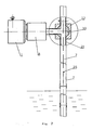
- the main detector body 1 and the sleeve coupling 8 are arranged on one side at the angle to the acoustic waveguide 4 ( Fig.6 and Fig. 7 ). Then the intermediate acoustic waveguide of ⁇ -shaped 20 ( Fig.6 ) or T-shaped 21 form ( Fig.7 ) is installed between the sleeve coupling 8 and acoustic waveguide 4, and the sleeve coupling 8 is connected to the part of the intermediate acoustic waveguide (20, 21) placed at the angle to the acoustic waveguide 4.
- the section of the intermediate acoustic waveguide from the sleeve coupling 8 to the axis of the acoustic waveguide 4 has the length in the range of see (2) 1 ⁇ 3 • c 2 ⁇ f 0 .
- a ball valve 22 can be installed with a cut off (overlapping) element 30 in the form of the ball with the holes as it is shown in Fig. 7 .
- the cavity 10 of the acoustic matching unit 9 is connected with the cavity of the acoustic waveguide 4, and in the another position the cavity of the acoustic waveguide 4 is connected with the environment.
- the acoustic waveguide 4 is executed of separate tubes 7 connected between themselves by means of adapters 23 which allows to mount them easily. Besides at the tubes joints the reflectors in the form of the washers 24 of the reflector can be installed with the diameter that differs from the internal diameter of the tube 7 ( Fig. 5 ).
- the reflectors 5 along the length of the tube 7 can be executed in the form of the holes 25 or in the form of the rods 26 fixed in the internal walls of the tubes 7 perpendicular to the axis of the acoustic waveguide 4 ( Fig. 5 ).
- the compensation holes 31 and 32 are executed in order to equalize pressure in the measured reservoir and the pressure in the cavity of the acoustical-electrical transducer 2 to provide normal operating condition of the membrane 6.
- a filter permeable to air and opaque to moisture is installed which can prevent a piezoelectric element 27 from operation.
- the liquid level detector operates in the following way.
- An impulse signal generator (not shown in figures) produces a periodic sequence of rectangular radio impulses in the narrow range of frequencies that are fed (for example) on the thin disk piezoelectric element 27. bending oscillations of the piezoelectric element 27 excite the membrane 6 radiating short impulse acoustic signals.
- the acoustic wave propagates through the cavity 10 0f the acoustic matching unit 9, along the channel 14 of the diaphragm 11 and propagate in the tube 7 of the acoustic waveguide 4 in the gas medium.
- the geometric dimensions of the cavity 10 of the acoustic matching unit 9 are selected in such a way that the output acoustic resistance of the membrane 6 and that of the load (acoustic channel with the waveguide) are equal.
- the acoustic matching unit 9 by selection of geometric dimensions is adjusted to resonance with the membrane 6 at the operating frequency.
- the acoustic wav When passing along the acoustic waveguide 4 the acoustic wav reflects from the reflectors 5 situated higher than the liquid level.
- the reflective properties of the reflectors 5 are selected in such away that the amplitude of the reflected signals was several times smaller (at least 10 times) than the amplitude of the signal reflected from the liquid surface.
- the reflectors 5 work as reference points the distance to which is known precisely before, that allows to take into consideration changing properties of the environment when processing the reflected signals.
- the reflectors 5 in the form of the holes 25 most often are combined with the reflectors in the form of the rods 26. If the holes 26 are closed, for example, by liquid drops due to the surface tension forces the reference points do remain.
- the holes 26 play as well the role of the drainage holes allowing to equalize the levels of the measured medium inside the waveguide and outside it even in case of layered medium.
- the acoustic waveguide 4 In the reception mode of signals reflected from the liquid surface and reflectors 5 the acoustic waveguide 4 is a source and is connected to the channel 14 of the acoustic matching unit 9. Wave resistance (or characteristic wave impedance) of the waveguide 7 is also appeared to be matched with the input resistance of the acoustic matching unit 9 and the membrane 6.
- the acoustic matching unit 9 reduces secondary signals reflections from the internal construction of the acoustic channel thus reducing secondary reflections of the acoustic signals.
- the ratio signal/noise is improved (the ratio of the legitimate signal to parasitic signals of multiple re-reflection), and finally, improves accuracy of the liquid level detector.
- the detector operates well when ⁇ -shaped or T-shaped intermediate acoustic waveguide is used it is necessary that the section length of the intermediate acoustic waveguide from the sleeve coupling to the axis of the acoustic waveguide be determined by the expression (2).
- the channel to the measuring device can be closed, and washing solution, for example, for reservoir and tubes cleaning can be fed into the cavity of the tube 7.
- washing solution for example, for reservoir and tubes cleaning
- the length of the line end cavities of the cut off element should meet the relation (2).
- a mechanical detector of the liquid level can be lowed through the tube cavity as well.
- the liquid level detector can be applied in different fields of technology for the level determination of any liquids including the aggressive ones. Its application allows to achieve greater noise immunity and accuracy of measurements.
Landscapes
- Physics & Mathematics (AREA)
- Acoustics & Sound (AREA)
- Electromagnetism (AREA)
- Thermal Sciences (AREA)
- Fluid Mechanics (AREA)
- General Physics & Mathematics (AREA)
- Measurement Of Levels Of Liquids Or Fluent Solid Materials (AREA)
- Investigating Or Analyzing Materials By The Use Of Ultrasonic Waves (AREA)
- Automatic Analysis And Handling Materials Therefor (AREA)
- Measurement Of Mechanical Vibrations Or Ultrasonic Waves (AREA)
Applications Claiming Priority (3)
| Application Number | Priority Date | Filing Date | Title |
|---|---|---|---|
| RU2001127653 | 2001-10-05 | ||
| RU2001127653A RU2193164C1 (ru) | 2001-10-05 | 2001-10-05 | Устройство для измерения уровня жидкости (варианты) |
| PCT/RU2002/000134 WO2003031919A1 (en) | 2001-10-05 | 2002-03-21 | Liquid level measuring device |
Publications (3)
| Publication Number | Publication Date |
|---|---|
| EP1434039A1 EP1434039A1 (en) | 2004-06-30 |
| EP1434039A4 EP1434039A4 (en) | 2005-08-31 |
| EP1434039B1 true EP1434039B1 (en) | 2012-05-09 |
Family
ID=20253708
Family Applications (1)
| Application Number | Title | Priority Date | Filing Date |
|---|---|---|---|
| EP02722998A Expired - Lifetime EP1434039B1 (en) | 2001-10-05 | 2002-03-21 | Liquid level measuring device |
Country Status (7)
| Country | Link |
|---|---|
| US (1) | US6983654B2 (da) |
| EP (1) | EP1434039B1 (da) |
| JP (1) | JP4034730B2 (da) |
| AT (1) | ATE557265T1 (da) |
| DK (1) | DK1434039T3 (da) |
| RU (1) | RU2193164C1 (da) |
| WO (1) | WO2003031919A1 (da) |
Families Citing this family (47)
| Publication number | Priority date | Publication date | Assignee | Title |
|---|---|---|---|---|
| US7117738B2 (en) * | 2003-10-02 | 2006-10-10 | Denso Corporation | Liquid level detecting apparatus |
| ATE399309T1 (de) * | 2003-10-15 | 2008-07-15 | Axsensor Ab | Messeinrichtung für fluidpegel |
| RU2249796C1 (ru) * | 2003-11-10 | 2005-04-10 | Гусев Александр Леонидович | Способ измерения уровня криогенной жидкости в сосуде и уровнемер для криогенных жидкостей |
| US20070169549A1 (en) * | 2006-01-23 | 2007-07-26 | Southwest Research Institute | Method and apparatus for sensing fuel levels in tanks |
| US7795783B2 (en) | 2006-04-26 | 2010-09-14 | Thermo Fisher Scientific Inc. | Transducer assembly |
| US8100006B2 (en) * | 2006-08-21 | 2012-01-24 | Engineering Technologies Canada Ltd. | Liquid level measurement device and installation incorporating the same |
| US8746045B2 (en) | 2006-11-17 | 2014-06-10 | Meggitt (Orange County), Inc. | System and method for identifying fluids and monitoring fluid quality in a vessel |
| MX2009005635A (es) * | 2006-11-28 | 2009-07-31 | Rubicon Res Pty Ltd | Dispositivo ultrasonico de deteccion de nivel con seccion ensanchada de distorsion reducida. |
| US8794063B2 (en) * | 2007-01-08 | 2014-08-05 | Meggitt (Orange County), Inc. | System and method for optimizing sweep delay and aliasing for time domain reflectometric measurement of liquid height within a tank |
| CN101034156B (zh) * | 2007-01-25 | 2010-05-19 | 西安交通大学 | 可抵消机械振动信号的压电式次声波传感器 |
| WO2008112220A1 (en) * | 2007-03-08 | 2008-09-18 | Davidson Instruments Inc. | Apparatus and methods for monitoring combustion dynamics in a gas turbine engine |
| US8322209B2 (en) * | 2007-08-07 | 2012-12-04 | Axsensor Ab | Liquid level measurement device and method |
| JP2010540942A (ja) | 2007-10-01 | 2010-12-24 | バイブロ−メーター インコーポレイテッド | 容器中の流体レベルを正確に測定するシステムおよび方法 |
| US8850893B2 (en) * | 2007-12-05 | 2014-10-07 | Valtion Teknillinen Tutkimuskeskus | Device for measuring pressure, variation in acoustic pressure, a magnetic field, acceleration, vibration, or the composition of a gas |
| US8104500B2 (en) * | 2008-04-18 | 2012-01-31 | Texas Institute Of Science, Inc. | Acoustic liquid level detection |
| US8002078B2 (en) * | 2009-02-19 | 2011-08-23 | Bose Corporation | Acoustic waveguide vibration damping |
| US8902704B2 (en) | 2010-03-22 | 2014-12-02 | Rohol-Aufsuchungs Ag | Method and device for logging the fluid depth in a wellbore |
| EA016638B1 (ru) * | 2010-03-31 | 2012-06-29 | Роэль-Ауфзухунгс Аг | Способ определения уровня пластовой жидкости в скважине и устройство для его осуществления |
| CN103261852B (zh) * | 2010-12-16 | 2015-07-15 | Vega格里沙贝两合公司 | 用于物位测量的测量装置、控制装置和测量仪器 |
| WO2012113776A1 (de) * | 2011-02-23 | 2012-08-30 | Gaslock Gmbh | Vorrichtung zur messung des füllstands von flüssigkeiten |
| EP2551846B1 (en) * | 2011-07-26 | 2022-01-19 | AKG Acoustics GmbH | Noise reducing sound reproduction |
| DE102012109405B4 (de) * | 2011-10-05 | 2020-11-12 | Dr. Hielscher Gmbh | Ultraschallsystem mit Ultraschallerzeuger, Resonator und Lichtquelle |
| RU2498234C1 (ru) * | 2012-03-06 | 2013-11-10 | Федеральное государственное автономное образовательное учреждение высшего профессионального образования "Национальный исследовательский ядерный университет "МИФИ" (НИЯУ МИФИ) | Устройство для измерения уровня жидкости |
| US9354101B2 (en) * | 2013-07-11 | 2016-05-31 | Axsensor Ab | Device for providing a gas composition and temperature compensated acoustic measurement of a liquid level |
| US9383246B2 (en) | 2013-09-06 | 2016-07-05 | Rosemount Tank Radar Ab | Sectioned probe for a radar level gauge |
| US10365146B2 (en) * | 2014-12-26 | 2019-07-30 | Ford Global Technologies, Llc | Method and system for engine cooling system control |
| EP3056877B1 (de) * | 2015-02-13 | 2020-12-02 | VEGA Grieshaber KG | Vibrationsmessanordnung |
| JP6384382B2 (ja) * | 2015-03-30 | 2018-09-05 | 日本精機株式会社 | 液面位置検出装置 |
| DE102015008992A1 (de) * | 2015-07-15 | 2017-01-19 | Hella Kgaa Hueck & Co. | Mediensensor mit mindestens einem Ultraschallwandler |
| JP6703775B2 (ja) * | 2016-05-20 | 2020-06-03 | 国立研究開発法人産業技術総合研究所 | 音波伝搬長測定方法、及び音波伝搬長測定装置 |
| RU170767U1 (ru) * | 2016-08-16 | 2017-05-05 | Акционерное общество "Высокотехнологический научно-исследовательский институт неорганических материалов имени академика А.А. Бочвара" | Ультразвуковой датчик уровня раздела сред |
| US10578479B2 (en) * | 2017-08-09 | 2020-03-03 | Fluke Corporation | Calibration bath with acoustic liquid level sensor |
| US10801877B2 (en) * | 2017-12-01 | 2020-10-13 | The Boeing Company | Ultrasonic fluid measurement calibration probe |
| DE102018202209B3 (de) * | 2018-02-13 | 2019-05-29 | Continental Automotive Gmbh | Vorrichtung zum Bestimmen einer Höhe und/oder Qualität eines Fluids in einem Fluidbehälter |
| RU2700286C2 (ru) * | 2018-02-14 | 2019-09-16 | Александр Петрович Демченко | Ультразвуковой датчик уровня жидкости |
| CN112714862A (zh) * | 2018-07-12 | 2021-04-27 | 艾伯林基督大学 | 高温管道中流量的非侵入性测量的装置、系统和方法 |
| US10787899B2 (en) * | 2018-07-17 | 2020-09-29 | Stephen Vaughn Judd | Resonant acoustic structure for measuring well or borehole depth |
| KR102161755B1 (ko) * | 2019-06-27 | 2020-10-05 | 주식회사 엔엔에프텍 | 지하수위계 |
| CN110687937B (zh) * | 2019-10-14 | 2021-09-28 | 东北大学 | 基于多变量广义最小方差解耦控制的水箱液位控制方法 |
| DE102020205194A1 (de) | 2020-04-23 | 2021-10-28 | Continental Automotive Gmbh | Sensorvorrichtung mit einem Ultraschallsensor |
| EP4083583A1 (en) * | 2021-04-30 | 2022-11-02 | Tekelek Group Holdings Limited | An ultrasonic distance sensor and a method for protecting an ultrasonic transducer in an ultrasonic distance sensor |
| CN118103239A (zh) * | 2021-10-15 | 2024-05-28 | 海拉有限双合股份公司 | 冷却剂箱、冷却剂引导系统和机动车 |
| US12467831B2 (en) | 2022-11-18 | 2025-11-11 | Georgia Tech Research Corporation | Molten salt sampling system and methods of use thereof |
| US12480860B2 (en) | 2022-12-07 | 2025-11-25 | Abilene Christian University | In-situ corrosion monitoring device and methods of use thereof |
| WO2025015124A2 (en) | 2023-07-11 | 2025-01-16 | Abilene Christian University | Nuclear reactor fluid level control system |
| US12444514B2 (en) | 2023-08-07 | 2025-10-14 | Abilene Christian University | Calibration of power monitors in molten salt reactors |
| EP4650619A1 (en) * | 2024-05-16 | 2025-11-19 | Rosemount Tank Radar AB | Field device with tunable damping arrangement and configuration method |
Family Cites Families (13)
| Publication number | Priority date | Publication date | Assignee | Title |
|---|---|---|---|---|
| JPS4831863B1 (da) * | 1965-03-08 | 1973-10-02 | ||
| CH546949A (fr) * | 1971-11-02 | 1974-03-15 | Zosi Emmanuel | Sonde de detection d'un depot solide dans un liquide. |
| SU599203A1 (ru) * | 1975-08-11 | 1978-03-25 | Всесоюзный научно-исследовательский и конструкторский институт "Цветметавтоматика" | Устройство дл контрол физических параметров жидких сред в закрытых емкост х |
| US4130018A (en) * | 1977-08-30 | 1978-12-19 | Envirotech Corporation | Ultrasonic transducer with reference reflector |
| US5184512A (en) * | 1989-01-16 | 1993-02-09 | Hrdlicka Armin W | Measuring the length of a column of fluid in a tube |
| FR2672678A1 (fr) | 1991-02-13 | 1992-08-14 | Geostock | Procede et dispositif pour la mesure et la surveillance du niveau d'un liquide, a partir d'un repere fixe, au moyen des ultrasons. |
| GB9205148D0 (en) * | 1992-03-10 | 1992-04-22 | Smiths Industries Plc | Liquid level gauging |
| CH681914A5 (da) * | 1992-03-31 | 1993-06-15 | Kuebler Ag Heinrich | |
| RU2037143C1 (ru) * | 1992-12-29 | 1995-06-09 | Товарищество с ограниченной ответственностью - фирма "Тевит" | Ультразвуковой датчик для измерения уровня жидкости |
| US5471872A (en) * | 1994-01-07 | 1995-12-05 | Semitool, Inc. | Acoustic liquid level measuring apparatus |
| US6612168B2 (en) * | 1995-05-11 | 2003-09-02 | Mts Systems Corporation | Explosion proof magnetostrictive probe |
| RU2127873C1 (ru) * | 1997-09-15 | 1999-03-20 | Николай Иванович Балин | Ультразвуковой датчик уровня жидкости |
| US6232769B1 (en) * | 1998-06-16 | 2001-05-15 | Balluff, Inc. | Modular waveguide assembly for a position sensor and method for making the same |
-
2001
- 2001-10-05 RU RU2001127653A patent/RU2193164C1/ru not_active IP Right Cessation
-
2002
- 2002-03-21 WO PCT/RU2002/000134 patent/WO2003031919A1/ru not_active Ceased
- 2002-03-21 EP EP02722998A patent/EP1434039B1/en not_active Expired - Lifetime
- 2002-03-21 AT AT02722998T patent/ATE557265T1/de active
- 2002-03-21 JP JP2003534852A patent/JP4034730B2/ja not_active Expired - Fee Related
- 2002-03-21 DK DK02722998.8T patent/DK1434039T3/da active
-
2004
- 2004-04-01 US US10/816,305 patent/US6983654B2/en not_active Expired - Fee Related
Also Published As
| Publication number | Publication date |
|---|---|
| WO2003031919A1 (en) | 2003-04-17 |
| RU2193164C1 (ru) | 2002-11-20 |
| JP2005504979A (ja) | 2005-02-17 |
| US6983654B2 (en) | 2006-01-10 |
| EP1434039A4 (en) | 2005-08-31 |
| JP4034730B2 (ja) | 2008-01-16 |
| ATE557265T1 (de) | 2012-05-15 |
| DK1434039T3 (da) | 2012-07-16 |
| EP1434039A1 (en) | 2004-06-30 |
| US20040182149A1 (en) | 2004-09-23 |
Similar Documents
| Publication | Publication Date | Title |
|---|---|---|
| EP1434039B1 (en) | Liquid level measuring device | |
| Silk et al. | The propagation in metal tubing of ultrasonic wave modes equivalent to Lamb waves | |
| JP3104956B2 (ja) | 混合ガスの音響分析装置と方法 | |
| US4679430A (en) | Ultrasonic liquid interface detector | |
| US5119676A (en) | Ultrasonic method and apparatus for determining water level in a closed vessel | |
| CN101676693B (zh) | 超声换能器 | |
| US4065958A (en) | Method of controlling physical characteristics of fluid medium | |
| CN113242959A (zh) | 超声仪器 | |
| CN103477194B (zh) | 用于超声流量测量装置的超声换能器的耦合元件 | |
| JP5504276B2 (ja) | 改善された指向性を有する音波変換器及びソナーアンテナ | |
| EP3710795B1 (en) | Device and method for detecting deposition layers in a conduit conducting a liquid or a soft medium and/or for level detection | |
| CN114111928A (zh) | 一种适用于气体流量检测的高频超声波传感器 | |
| CN114111927B (zh) | 一种适用于气体流量检测的高频超声波传感器 | |
| US10677757B2 (en) | Method for acoustically determining properties of a medium, and device for acoustically determining properties of a medium, comprising a reflective element | |
| US20200024940A1 (en) | Resonant acoustic structure for measuring well or borehole depth | |
| RU2661455C1 (ru) | Способ определения вязкоупругих свойств жидких и твёрдых сред и устройство для его реализации | |
| JP2003106880A (ja) | 超音波送受信装置 | |
| Royer et al. | A liquid level sensor using the absorption of guided acoustic waves | |
| JP3256608B2 (ja) | 超音波水位計測方法およびその装置 | |
| JPS61132822A (ja) | 超音波流量計 | |
| US11150123B2 (en) | System for measuring a filling level | |
| RU2844729C1 (ru) | Ультразвуковой преобразователь для эхолокационного уровнемера | |
| GB2427273A (en) | Fluid level sensor using Rayleigh-Lamb waves | |
| JP2685590B2 (ja) | 超音波送受信装置 | |
| JP2883057B2 (ja) | 超音波送受波器 |
Legal Events
| Date | Code | Title | Description |
|---|---|---|---|
| PUAI | Public reference made under article 153(3) epc to a published international application that has entered the european phase |
Free format text: ORIGINAL CODE: 0009012 |
|
| 17P | Request for examination filed |
Effective date: 20031215 |
|
| AK | Designated contracting states |
Kind code of ref document: A1 Designated state(s): AT BE CH CY DE DK ES FI FR GB GR IE IT LI LU MC NL PT SE TR |
|
| A4 | Supplementary search report drawn up and despatched |
Effective date: 20050714 |
|
| 17Q | First examination report despatched |
Effective date: 20070614 |
|
| GRAP | Despatch of communication of intention to grant a patent |
Free format text: ORIGINAL CODE: EPIDOSNIGR1 |
|
| GRAS | Grant fee paid |
Free format text: ORIGINAL CODE: EPIDOSNIGR3 |
|
| GRAA | (expected) grant |
Free format text: ORIGINAL CODE: 0009210 |
|
| AK | Designated contracting states |
Kind code of ref document: B1 Designated state(s): AT BE CH CY DE DK ES FI FR GB GR IE IT LI LU MC NL PT SE TR |
|
| REG | Reference to a national code |
Ref country code: GB Ref legal event code: FG4D |
|
| REG | Reference to a national code |
Ref country code: CH Ref legal event code: EP Ref country code: AT Ref legal event code: REF Ref document number: 557265 Country of ref document: AT Kind code of ref document: T Effective date: 20120515 |
|
| REG | Reference to a national code |
Ref country code: IE Ref legal event code: FG4D |
|
| REG | Reference to a national code |
Ref country code: DE Ref legal event code: R096 Ref document number: 60242871 Country of ref document: DE Effective date: 20120705 |
|
| REG | Reference to a national code |
Ref country code: DK Ref legal event code: T3 |
|
| REG | Reference to a national code |
Ref country code: NL Ref legal event code: VDEP Effective date: 20120509 |
|
| PG25 | Lapsed in a contracting state [announced via postgrant information from national office to epo] |
Ref country code: SE Free format text: LAPSE BECAUSE OF FAILURE TO SUBMIT A TRANSLATION OF THE DESCRIPTION OR TO PAY THE FEE WITHIN THE PRESCRIBED TIME-LIMIT Effective date: 20120509 Ref country code: FI Free format text: LAPSE BECAUSE OF FAILURE TO SUBMIT A TRANSLATION OF THE DESCRIPTION OR TO PAY THE FEE WITHIN THE PRESCRIBED TIME-LIMIT Effective date: 20120509 Ref country code: CY Free format text: LAPSE BECAUSE OF FAILURE TO SUBMIT A TRANSLATION OF THE DESCRIPTION OR TO PAY THE FEE WITHIN THE PRESCRIBED TIME-LIMIT Effective date: 20120509 |
|
| REG | Reference to a national code |
Ref country code: AT Ref legal event code: MK05 Ref document number: 557265 Country of ref document: AT Kind code of ref document: T Effective date: 20120509 |
|
| PG25 | Lapsed in a contracting state [announced via postgrant information from national office to epo] |
Ref country code: PT Free format text: LAPSE BECAUSE OF FAILURE TO SUBMIT A TRANSLATION OF THE DESCRIPTION OR TO PAY THE FEE WITHIN THE PRESCRIBED TIME-LIMIT Effective date: 20120910 Ref country code: GR Free format text: LAPSE BECAUSE OF FAILURE TO SUBMIT A TRANSLATION OF THE DESCRIPTION OR TO PAY THE FEE WITHIN THE PRESCRIBED TIME-LIMIT Effective date: 20120810 |
|
| PG25 | Lapsed in a contracting state [announced via postgrant information from national office to epo] |
Ref country code: BE Free format text: LAPSE BECAUSE OF FAILURE TO SUBMIT A TRANSLATION OF THE DESCRIPTION OR TO PAY THE FEE WITHIN THE PRESCRIBED TIME-LIMIT Effective date: 20120509 |
|
| PG25 | Lapsed in a contracting state [announced via postgrant information from national office to epo] |
Ref country code: NL Free format text: LAPSE BECAUSE OF FAILURE TO SUBMIT A TRANSLATION OF THE DESCRIPTION OR TO PAY THE FEE WITHIN THE PRESCRIBED TIME-LIMIT Effective date: 20120509 Ref country code: AT Free format text: LAPSE BECAUSE OF FAILURE TO SUBMIT A TRANSLATION OF THE DESCRIPTION OR TO PAY THE FEE WITHIN THE PRESCRIBED TIME-LIMIT Effective date: 20120509 |
|
| PLBE | No opposition filed within time limit |
Free format text: ORIGINAL CODE: 0009261 |
|
| STAA | Information on the status of an ep patent application or granted ep patent |
Free format text: STATUS: NO OPPOSITION FILED WITHIN TIME LIMIT |
|
| 26N | No opposition filed |
Effective date: 20130212 |
|
| PG25 | Lapsed in a contracting state [announced via postgrant information from national office to epo] |
Ref country code: ES Free format text: LAPSE BECAUSE OF FAILURE TO SUBMIT A TRANSLATION OF THE DESCRIPTION OR TO PAY THE FEE WITHIN THE PRESCRIBED TIME-LIMIT Effective date: 20120820 |
|
| REG | Reference to a national code |
Ref country code: DE Ref legal event code: R097 Ref document number: 60242871 Country of ref document: DE Effective date: 20130212 |
|
| PG25 | Lapsed in a contracting state [announced via postgrant information from national office to epo] |
Ref country code: MC Free format text: LAPSE BECAUSE OF NON-PAYMENT OF DUE FEES Effective date: 20130331 |
|
| REG | Reference to a national code |
Ref country code: CH Ref legal event code: PL |
|
| GBPC | Gb: european patent ceased through non-payment of renewal fee |
Effective date: 20130321 |
|
| REG | Reference to a national code |
Ref country code: IE Ref legal event code: MM4A |
|
| PG25 | Lapsed in a contracting state [announced via postgrant information from national office to epo] |
Ref country code: IE Free format text: LAPSE BECAUSE OF NON-PAYMENT OF DUE FEES Effective date: 20130321 Ref country code: LI Free format text: LAPSE BECAUSE OF NON-PAYMENT OF DUE FEES Effective date: 20130331 Ref country code: CH Free format text: LAPSE BECAUSE OF NON-PAYMENT OF DUE FEES Effective date: 20130331 Ref country code: GB Free format text: LAPSE BECAUSE OF NON-PAYMENT OF DUE FEES Effective date: 20130321 |
|
| PG25 | Lapsed in a contracting state [announced via postgrant information from national office to epo] |
Ref country code: TR Free format text: LAPSE BECAUSE OF FAILURE TO SUBMIT A TRANSLATION OF THE DESCRIPTION OR TO PAY THE FEE WITHIN THE PRESCRIBED TIME-LIMIT Effective date: 20120509 |
|
| PG25 | Lapsed in a contracting state [announced via postgrant information from national office to epo] |
Ref country code: LU Free format text: LAPSE BECAUSE OF NON-PAYMENT OF DUE FEES Effective date: 20130321 |
|
| REG | Reference to a national code |
Ref country code: FR Ref legal event code: PLFP Year of fee payment: 15 |
|
| REG | Reference to a national code |
Ref country code: FR Ref legal event code: PLFP Year of fee payment: 16 |
|
| REG | Reference to a national code |
Ref country code: FR Ref legal event code: PLFP Year of fee payment: 17 |
|
| PGFP | Annual fee paid to national office [announced via postgrant information from national office to epo] |
Ref country code: DE Payment date: 20200306 Year of fee payment: 19 Ref country code: IT Payment date: 20200331 Year of fee payment: 19 Ref country code: DK Payment date: 20200320 Year of fee payment: 19 |
|
| PGFP | Annual fee paid to national office [announced via postgrant information from national office to epo] |
Ref country code: FR Payment date: 20200401 Year of fee payment: 19 |
|
| REG | Reference to a national code |
Ref country code: DE Ref legal event code: R119 Ref document number: 60242871 Country of ref document: DE |
|
| REG | Reference to a national code |
Ref country code: DK Ref legal event code: EBP Effective date: 20210331 |
|
| PG25 | Lapsed in a contracting state [announced via postgrant information from national office to epo] |
Ref country code: FR Free format text: LAPSE BECAUSE OF NON-PAYMENT OF DUE FEES Effective date: 20210331 Ref country code: DE Free format text: LAPSE BECAUSE OF NON-PAYMENT OF DUE FEES Effective date: 20211001 |
|
| PG25 | Lapsed in a contracting state [announced via postgrant information from national office to epo] |
Ref country code: IT Free format text: LAPSE BECAUSE OF NON-PAYMENT OF DUE FEES Effective date: 20210321 Ref country code: DK Free format text: LAPSE BECAUSE OF NON-PAYMENT OF DUE FEES Effective date: 20210331 |