EP1434009A1 - Spiessstütze, Gerät mit einer solchen Stütze und Elektroherd mit einem solchen Gerät - Google Patents
Spiessstütze, Gerät mit einer solchen Stütze und Elektroherd mit einem solchen Gerät Download PDFInfo
- Publication number
- EP1434009A1 EP1434009A1 EP03293308A EP03293308A EP1434009A1 EP 1434009 A1 EP1434009 A1 EP 1434009A1 EP 03293308 A EP03293308 A EP 03293308A EP 03293308 A EP03293308 A EP 03293308A EP 1434009 A1 EP1434009 A1 EP 1434009A1
- Authority
- EP
- European Patent Office
- Prior art keywords
- support
- spindle
- frame
- oven
- equipment
- Prior art date
- Legal status (The legal status is an assumption and is not a legal conclusion. Google has not performed a legal analysis and makes no representation as to the accuracy of the status listed.)
- Granted
Links
- 239000004519 grease Substances 0.000 claims abstract description 8
- 239000003925 fat Substances 0.000 claims description 41
- 238000011084 recovery Methods 0.000 claims description 37
- 238000010411 cooking Methods 0.000 claims description 13
- 230000000295 complement effect Effects 0.000 claims description 8
- 239000002184 metal Substances 0.000 claims description 8
- 238000011144 upstream manufacturing Methods 0.000 claims description 4
- 238000006073 displacement reaction Methods 0.000 abstract description 2
- 235000019197 fats Nutrition 0.000 description 34
- 235000013372 meat Nutrition 0.000 description 14
- 230000002093 peripheral effect Effects 0.000 description 9
- 238000009434 installation Methods 0.000 description 4
- 238000012986 modification Methods 0.000 description 4
- 230000004048 modification Effects 0.000 description 4
- 238000012423 maintenance Methods 0.000 description 2
- 238000004519 manufacturing process Methods 0.000 description 2
- 238000005452 bending Methods 0.000 description 1
- 235000014541 cooking fats Nutrition 0.000 description 1
- 238000000151 deposition Methods 0.000 description 1
- 238000011161 development Methods 0.000 description 1
- 230000018109 developmental process Effects 0.000 description 1
- 235000013305 food Nutrition 0.000 description 1
- 235000011389 fruit/vegetable juice Nutrition 0.000 description 1
- 238000005304 joining Methods 0.000 description 1
- 244000144977 poultry Species 0.000 description 1
- 238000003825 pressing Methods 0.000 description 1
- 230000002787 reinforcement Effects 0.000 description 1
- XLYOFNOQVPJJNP-UHFFFAOYSA-N water Substances O XLYOFNOQVPJJNP-UHFFFAOYSA-N 0.000 description 1
- 238000003466 welding Methods 0.000 description 1
Images

Classifications
-
- F—MECHANICAL ENGINEERING; LIGHTING; HEATING; WEAPONS; BLASTING
- F24—HEATING; RANGES; VENTILATING
- F24C—DOMESTIC STOVES OR RANGES ; DETAILS OF DOMESTIC STOVES OR RANGES, OF GENERAL APPLICATION
- F24C15/00—Details
- F24C15/16—Shelves, racks or trays inside ovens; Supports therefor
- F24C15/164—Rotisserie spits inside ovens
-
- F—MECHANICAL ENGINEERING; LIGHTING; HEATING; WEAPONS; BLASTING
- F24—HEATING; RANGES; VENTILATING
- F24C—DOMESTIC STOVES OR RANGES ; DETAILS OF DOMESTIC STOVES OR RANGES, OF GENERAL APPLICATION
- F24C15/00—Details
- F24C15/16—Shelves, racks or trays inside ovens; Supports therefor
-
- A—HUMAN NECESSITIES
- A47—FURNITURE; DOMESTIC ARTICLES OR APPLIANCES; COFFEE MILLS; SPICE MILLS; SUCTION CLEANERS IN GENERAL
- A47J—KITCHEN EQUIPMENT; COFFEE MILLS; SPICE MILLS; APPARATUS FOR MAKING BEVERAGES
- A47J37/00—Baking; Roasting; Grilling; Frying
- A47J37/04—Roasting apparatus with movably-mounted food supports or with movable heating implements; Spits
- A47J37/049—Details of the food supports not specially adapted to one of the preceding types of food supports
Definitions
- the invention relates in particular to a spindle support for an oven of the household appliance type.
- Such a spindle support takes, for example, the appearance of a frame rigid made of metal wire and whose general shape is substantially in a plan.
- the frame that forms a closed structure has two portions lateral and two longitudinal portions.
- the oven meanwhile, has an internal cooking cavity which is delimited by a wall forming the lateral internal faces, of the bottom, of the below and above the cavity, the oven door closing this cavity.
- elements in relief with shapes convex are provided to receive all or part of the lateral portions of the frame when the latter is introduced into the oven cavity by the user.
- the frame slides, by means of its lateral portions, on the elements in relief which, generally, take the form of steps or of pressings.
- the spit carrying the meat to be cooked is positioned on the frame at the two locations provided for this purpose.
- These locations are materialized, for example, by parts of the frame where the metal wire is deformed towards the internal face of the bottom of the cavity so as to each form a concave zone which is used to receive one of the two ends of the spindle.
- the pin is also positioned in holes made in the internal faces of the cavity so that the pin can be rotated by the motor disposed behind one of these faces internal.
- a fat recovery dish is introduced into the cavity from the oven in the lower part to collect the fat from the cooking of the meat that is placed on top.
- This dish is also based on relief elements arranged on the lateral internal faces of the wall delimiting the cavity.
- the user opens the oven door and remove the spit holder and the spit from the internal cooking cavity to remove the skewered meat from the oven.
- the present invention aims to remedy at least one of the disadvantages mentioned above by proposing a spindle support for an oven of the type household appliance, characterized in that the spindle support has joining means which make it suitable for being attached to a dish of fat recovery in an oven, following at least one direction of displacement of the equipment consisting of the support and the dish and which corresponds in the direction of removal of this equipment from the oven, the spindle support also comprising support means which make it suitable for cooperating with a wall defining an internal cavity in the oven.
- the spit holder when it supports a meat to roasted skewered, continues to be supported mainly by the wall defining the internal cavity of the oven, which simplifies the modifications to be made to a conventional spindle holder and to a fat recovery dish conventional.
- the weight resulting from the spindle holder and the associated spit is always mainly supported by the wall defining the internal cavity of the oven.
- the spindle support is present under the shape of a rigid frame that has at least two separate locations able to each receive one end of a pin.
- the rigid frame is made of wire metallic.
- the framework of the spindle support forms a closed structure.
- the means for securing the support are reported to said executive.
- the means for securing the support of spindle are formed of fixing lugs of which at least part is able to engage in recesses made in the recovery dish fats.
- the fixing lugs are made up of straight portions of metal wire reported substantially perpendicularly to the general shape of the frame.
- the means of securing of the support are formed areas of the frame which are deformed locally so as to cooperate with complementary developments provided in the fat recovery dish.
- the deformed zones of the frame are able to engage in recesses arranged in the dish fat recovery.
- the zones deformed frame have a U shape.
- the frame of the support spindle forms an open structure having two ends which constitute the means for securing the support to the fat recovery dish.
- an open structure frame facilitates manipulation of the spindle by the user since a free space is provided between the two ends of the frame.
- the shape of the frame constituting the spindle support according to the invention is easily obtained from the initial shape of a frame conventional closed structure by opening the latter and bending the ends.
- one of the curved ends of the frame is placed near one of the locations which is suitable for receiving a end of a pin, the part of the frame disposed between said end curved and the location considered being curved towards the part of the frame arranged immediately upstream of said location relative to the end.
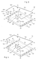
- an appliance type appliance comprises a spindle support 12, and a dish for collecting fats 14.
- the fat recovery dish 14 has a portion central forming a hollow 16, intended to recover the greases and, at the periphery of the latter, a strip forming a peripheral rim 18 and allowing in particular the gripping of the dish by the user, as well as its installation and maintenance inside an oven.
- the rim 18 has two long longitudinal sides or longitudinal portions 18a and 18b arranged opposite and two short sides side or side portions 18c and 18d, also arranged opposite.
- side portions 18c and 18d are identical to same as the longitudinal portions 18a and 18b, which thus allows introduce the dish into an oven either by the longitudinal portion 18a or by the longitudinal portion 18b.
- the spindle support 12 is in the form of a frame rigid device which is more particularly made of metal wire.
- the frame forms a closed structure of generally planar shape.
- the frame 12 has two longitudinal portions 12a and 12b, mutually parallel, arranged opposite, as well as two lateral portions 12c and 12d also parallel to each other and arranged opposite;
- each of the longitudinal portions 12a and 12b is provided a location noted 32 for the longitudinal portion 12a and 34 for the portion longitudinal 12b.
- Each of these locations is in the form of a more or less pronounced local deformation directed downwards in the representation which makes on figure 1, so that the local area as well concave deformed constitutes a housing suitable for receiving one of the ends of the aforementioned paperback.
- the spindle support 12 according to the invention also comprises two legs produced by portions of metal wire which are attached to the frame substantially perpendicular to the general shape of the latter, for example, by welding.
- These legs 36, 38 constitute securing means which make the spindle support 12 able to be secured to the recovery dish greases 14 following at least one direction of movement of the equipment consisting of the support and the dish relative to the oven, as is will see later during the description made with reference to FIG. 2.
- the direction of movement in question corresponds to the direction that the equipment in question is removed from the oven.
- this direction is perpendicular to the plane in which the peripheral edge 18 of the plate 14 extends.
- the above-mentioned securing means 36, 38 cooperate with additional means provided on the fat recovery dish 14, and which in this case are the recesses 24 and 26.
- spindle support can also be secured to the dish via the other recesses 28 and 30 arranged in the longitudinal portion 18b.
- the equipment consisting of the support spindle with its spindle and the dish can be translated in a direction perpendicular to the alignment axis of legs 36 and 38, as if this equipment was made of a single piece.
- the equipment thus formed according to the invention is particularly simple to manufacture insofar as it takes up a support of spit and a conventional fat collection dish.
- recesses 24 and 26, 28 and 30 made in the fat recovery dish 14 may or may not be through.
- FIG 2 there is shown the equipment of Figure 1 installed in a household appliance oven 40 partially shown so schematic, once the spindle support is coupled to the flat fat recovery.
- the oven 40 has a wall 42 which defines an internal cooking cavity in the oven 44 by means of these lateral internal faces, of its internal face of the bottom, of its internal face of the below and its inner face from above.
- a hinged door 46 having an internal face 46a is shown in the open position in Figure 2 and, when in position closed, it closes the internal cooking cavity of the oven.
- the lateral internal face 42b is provided with elements in relief of convex shapes arranged, for example, in the form of steps 48, 50 and 52.
- this lateral portion may not be carried out when no roasting meat is placed on the spit support.
- the user can push the equipment inside the oven, into the internal cavity 44, making slide the lateral portion 18d of the peripheral rim 18 and the lateral portion 12d of the frame 12 respectively on the upper parts 48a and 50a of the bleachers 48 and 50.
- the lateral portions 12c and 12d of the frame of the support for spindle according to the invention constitute support means which make the support pin adapted to cooperate with the lateral internal faces of the wall 42 of the oven.
- these supports are generally made up when skewered meat is positioned on the support but not necessarily in the absence of the meat.
- the spindle support according to the invention is only attached to the fat recovery dish by through the two legs 36 and 38, if the frame was not supported by through its side portions on the steps of the oven wall, it additional legs should be added to said frame in order to engage in the corresponding recesses 28 and 30, thereby distributing the load exerted on this framework.
- the invention thus makes it possible to water skewered meat during cooking by removing in one operation, both the support spit and the fat collection dish located below, in the direction indicated by the arrow marked R in FIG. 2.
- the invention makes it possible to position the spindle in the axis of the motor not represented by performing a simple translation of the equipment consisting of support for spit and grease collecting dish.
- Figure 3 is shown a second embodiment equipment for a household appliance according to the invention.
- the equipment shown, marked 60 includes a support for pin 62 which is provided with means making it possible to secure it at least in a direction to the fat recovery dish identical to that of the figures 1 and 2.
- the spindle support 62 is in the form of a frame rigid device forming an open structure unlike the structure closed frame 12 shown in Figures 1 and 2.
- the frame 62 has a large rear longitudinal portion 62a and two small lateral portions 62b and 62c which are arranged opposite one from the other.
- the portions 62d and 62e are shaped so as to spare between them a free space allowing access to the interior of the frame.
- the portion 62d also comprises, on the one hand, a second section 62i which extends perpendicular to the first section, in a plane perpendicular to the plane defined by the portions 62a, 62b, and 62c, this second section extending over a small height and, on the other hand, a third section 62j which extends perpendicular to the second section, always in the same vertical plane perpendicular to the plane defined by the portions 62a, 62b, 62c.
- the third section 62j thus forms a return and ends with the end 62f which is bent, still in the vertical plane, downwards in order to be able to be inserted into one of the corresponding recesses in the dish 14.
- This portion 62e comprises a second section 621 which extends to from the free end of the first section, perpendicular to the defined plane by the portions 62a, 62b, and 62c downwards, over a small height which corresponds to that of the second section 62i of the lateral portion 62d.
- the third section 62m extends perpendicular to the second section 62l so as to form a return with respect to the first section 62k.
- the 62g end is bent down towards the flat fat recovery so that it can be inserted into the recess correspondent 26 of the latter.
- the folded structure of sections 62d and 62e upstream of curved ends of the frame stiffens these areas of the frame and thus give said frame sufficient general mechanical strength to the use made of it.
- the mechanical reinforcement provided by the structure of the portion 62e is particularly useful for supporting the weight transmitted by the spindle, one of which end will rest at location 32.
- FIG. 4 illustrates an alternative embodiment of the equipment 60 shown in Figure 3 in which the equipment 70 consists of a dish of recovery of the greases 14 and of a spindle support 72 with an open structure, one end of which differs from that of the support shown in Figure 3.
- the spindle support 70 has portions 72a, 72b, 72c identical to the portions 62a, 62b, 62c of the frame 62 of FIG. 3.
- the frame 72 finally comprises a second front portion 72l which extends, via a first section 72i, from the end lateral 72b, over a very short distance towards the opposite end of the lateral portion 72c, then extends along a second section 72j, perpendicularly, downwards, in a plane perpendicular to the plane defined by portions 72a, 72b, and 72c.
- This second section 72j ends with a 72k end intended to be inserted into the corresponding recess 24 of the plate 14.
- the return formed by the first section 72i in the plane defined by the portions 72a, 72b, 72c gives this part of the frame a certain rigidity of same as the deployment of the second section 72j in a perpendicular plane vertical.
- the shape of the spindle support 62 or 72 allows recover the fat juices accumulated in the dish 14 and sprinkle the meat during its cooking, while remaining permanently above the dish, thus preventing any risk of fat depositing out of the dish and especially on the door 46.
- the opening thus formed between the front portions 62d and 62e for the equipment 60 of FIG. 3, and front portions 72l and 72d for the equipment 70 of FIG. 4, allows the user to more easily access the pin when it is in position on the support, for example, to come the remove from this support or even to perform various manipulations inside from the oven.
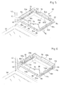
- equipment 80 for an oven of the household appliance type comprises a spindle support 82, and a dish for collecting fats 84, as shown in FIG. 5.
- the fat recovery dish 84 has a portion central forming a hollow 86, intended to recover the greases and, at the periphery of the latter, a strip forming a peripheral rim 88 and allowing in particular the gripping of the dish by the user, as well as its installation and maintenance inside an oven.
- the rim 88 has two long longitudinal sides or longitudinal portions 88a and 88b arranged opposite and two short sides lateral or lateral portions 88c and 88d, also arranged opposite.
- the lateral portions 88c and 88d are identical with same as the longitudinal portions 88a and 88b, which thus allows introduce the dish into an oven either by the longitudinal portion 88a or by the longitudinal portion 88b.
- the dish also has two interior recesses arranged in the portions 88a and 88b of the strip 88 in order to constitute each a hook or shoulder in the thickness of the strip.
- the spindle support 82 is in the form of a frame rigid device which is more particularly made of metal wire.
- the frame forms a closed structure of general shape substantially flat.
- the frame 82 has two longitudinal portions 82a, 82b, mutually parallel, arranged opposite, as well as two lateral portions 82c and 82d also parallel to each other and arranged opposite.
- each of the longitudinal portions 82a and 82b is provided a location noted 94 for the longitudinal portion 82a and 96 for the portion longitudinal 82b.
- Each of these locations is in the form of a more or less pronounced local deformation directed downwards to location 94, so that the local area thus deformed constitutes a housing capable of receiving one of the ends of the aforementioned pin.
- the spindle support also includes means for securing the support 82 to the plate 84 which are formed from zones of the frame locally deformed downward, substantially perpendicular to the shape general of the frame.
- the deformed areas are are in the form of U-shaped hooks 100, 102 and 104 ensuring the feet function for the support which thus comes to bear on the dish 84.
- feet are, for example, three in number but there could be having only two or more than three without affecting the principle of the invention.
- the two feet 102 and 104 rest on the inner shoulder 84b while the foot 100 rests on the inner shoulder 84a.
- the deformed zones 100, 102 and 104 of the frame thus ensure the securing the support 82 to the plate 84 in one direction, during movement described above.
- the three-legged support variant provides great stability support, especially when equipped with its spit and skewered meat.
- the deformations thus created also confer good mechanical rigidity to support.
- the support 82 also has a portion 98 angled horizontally inward of the frame, providing rigidity mechanical to the part of the frame (location 94) which will receive one end of the spindle.
- FIG. 6 includes the same elements as those of Figure 5 and they will therefore not be described again here.
- the unchanged elements keep the same references.
- the deformed zones of the frame which have the form of U-shaped hooks or slots are four in number, 110, 112, 114 and 116, and are produced in the lateral portions 118c and 118d of the frame and not in the longitudinal portions 118a and 118b.
- these feet 110, 112, 114 and 116 are able to engage in recesses formed by the openings 90 and 92 of the lateral portions 88c and 88d of the dish 84.
- the lateral portions of the support also have deformations horizontal.
- each lateral portion 118c, 118d is not only locally deformed into two downward regions to form a U, but also in a horizontal plane, towards the inside of the frame.
- the spindle support 118 is made integral with the plate 84 in two directions: the direction of advance in the oven or withdrawal of the oven and the direction perpendicular to it.
- the four feet provide good stability to the spindle support but it would however have been possible to have only two feet on one side and one of the other.
- this alternative embodiment has all the advantages which have been described for the variant of FIG. 5 and the embodiment of the Figures 1 and 2.
- the spindle support frame of this other variant comprises at least three locally deformed zones in order to constitute feet for the support, two of them cooperating with openings 90, 92 and the third for stability with the shoulder 84a or 84b.
Landscapes
- Engineering & Computer Science (AREA)
- Chemical & Material Sciences (AREA)
- Combustion & Propulsion (AREA)
- Mechanical Engineering (AREA)
- General Engineering & Computer Science (AREA)
- Baking, Grill, Roasting (AREA)
- Food-Manufacturing Devices (AREA)
- Electric Stoves And Ranges (AREA)
- Supports Or Holders For Household Use (AREA)
- Resistance Heating (AREA)
Applications Claiming Priority (2)
| Application Number | Priority Date | Filing Date | Title |
|---|---|---|---|
| FR0216536 | 2002-12-23 | ||
| FR0216536A FR2849168B1 (fr) | 2002-12-23 | 2002-12-23 | Support de broche, equipement comprenant un tel support et four electromenager comprenant un tel equipement. |
Publications (2)
| Publication Number | Publication Date |
|---|---|
| EP1434009A1 true EP1434009A1 (de) | 2004-06-30 |
| EP1434009B1 EP1434009B1 (de) | 2010-11-24 |
Family
ID=32406413
Family Applications (1)
| Application Number | Title | Priority Date | Filing Date |
|---|---|---|---|
| EP03293308A Expired - Lifetime EP1434009B1 (de) | 2002-12-23 | 2003-12-23 | Spiessstütze, Gerät mit einer solchen Stütze und Elektroherd mit einem solchen Gerät |
Country Status (5)
| Country | Link |
|---|---|
| EP (1) | EP1434009B1 (de) |
| AT (1) | ATE489586T1 (de) |
| DE (1) | DE60335073D1 (de) |
| ES (1) | ES2356124T3 (de) |
| FR (1) | FR2849168B1 (de) |
Cited By (4)
| Publication number | Priority date | Publication date | Assignee | Title |
|---|---|---|---|---|
| DE102007015247A1 (de) * | 2007-03-29 | 2008-10-02 | BSH Bosch und Siemens Hausgeräte GmbH | Hausgerätevorrichtung |
| CN101120860B (zh) * | 2006-08-10 | 2011-03-02 | 乐金电子(天津)电器有限公司 | 具有防油渍的烧烤盘烧烤架结构 |
| DE102011088075A1 (de) * | 2011-12-09 | 2013-06-13 | BSH Bosch und Siemens Hausgeräte GmbH | Behandlungsgutträger für einen Behandlungsraum eines Lebensmittels |
| EP1892475A3 (de) * | 2006-08-23 | 2016-12-28 | Electrolux Home Products, Inc. | Vorrichtung mit Backbleck und Abtropfblech |
Citations (4)
| Publication number | Priority date | Publication date | Assignee | Title |
|---|---|---|---|---|
| US2985096A (en) * | 1956-11-05 | 1961-05-23 | Whirlpool Co | Rotisserie apparatus |
| US3691937A (en) * | 1971-02-04 | 1972-09-19 | Gen Electric | Combined broiler pan and broil rack |
| NL7706187A (en) * | 1977-06-03 | 1978-12-05 | Atag Bv Apparatenfab | Oven or rotary grill with drive motor - has non-coinciding motor and rotary grill shaft axes |
| US5171951A (en) * | 1990-01-10 | 1992-12-15 | Moulinex (Societe Anonyme) | Combined microwave and resistance heated electric oven |
-
2002
- 2002-12-23 FR FR0216536A patent/FR2849168B1/fr not_active Expired - Fee Related
-
2003
- 2003-12-23 EP EP03293308A patent/EP1434009B1/de not_active Expired - Lifetime
- 2003-12-23 AT AT03293308T patent/ATE489586T1/de not_active IP Right Cessation
- 2003-12-23 ES ES03293308T patent/ES2356124T3/es not_active Expired - Lifetime
- 2003-12-23 DE DE60335073T patent/DE60335073D1/de not_active Expired - Lifetime
Patent Citations (4)
| Publication number | Priority date | Publication date | Assignee | Title |
|---|---|---|---|---|
| US2985096A (en) * | 1956-11-05 | 1961-05-23 | Whirlpool Co | Rotisserie apparatus |
| US3691937A (en) * | 1971-02-04 | 1972-09-19 | Gen Electric | Combined broiler pan and broil rack |
| NL7706187A (en) * | 1977-06-03 | 1978-12-05 | Atag Bv Apparatenfab | Oven or rotary grill with drive motor - has non-coinciding motor and rotary grill shaft axes |
| US5171951A (en) * | 1990-01-10 | 1992-12-15 | Moulinex (Societe Anonyme) | Combined microwave and resistance heated electric oven |
Cited By (4)
| Publication number | Priority date | Publication date | Assignee | Title |
|---|---|---|---|---|
| CN101120860B (zh) * | 2006-08-10 | 2011-03-02 | 乐金电子(天津)电器有限公司 | 具有防油渍的烧烤盘烧烤架结构 |
| EP1892475A3 (de) * | 2006-08-23 | 2016-12-28 | Electrolux Home Products, Inc. | Vorrichtung mit Backbleck und Abtropfblech |
| DE102007015247A1 (de) * | 2007-03-29 | 2008-10-02 | BSH Bosch und Siemens Hausgeräte GmbH | Hausgerätevorrichtung |
| DE102011088075A1 (de) * | 2011-12-09 | 2013-06-13 | BSH Bosch und Siemens Hausgeräte GmbH | Behandlungsgutträger für einen Behandlungsraum eines Lebensmittels |
Also Published As
| Publication number | Publication date |
|---|---|
| DE60335073D1 (de) | 2011-01-05 |
| FR2849168B1 (fr) | 2005-03-11 |
| ES2356124T3 (es) | 2011-04-05 |
| FR2849168A1 (fr) | 2004-06-25 |
| ATE489586T1 (de) | 2010-12-15 |
| EP1434009B1 (de) | 2010-11-24 |
Similar Documents
| Publication | Publication Date | Title |
|---|---|---|
| EP1491122B1 (de) | Elektrisches Haushaltsgerät | |
| EP2059985A1 (de) | Installationsmechanismus zur anbringung hinter einer installationshalterung und elektrische geräte mit einem solchen mechanismus | |
| EP1237453B1 (de) | Griffelement für kochgeschirr | |
| WO2002021985A1 (fr) | Appareil culinaire a plaque de cuisson amovible par dispositif de blocage et deblocage | |
| FR2892008A3 (fr) | Appareil a frire ou cuire inclinable | |
| EP3368376A1 (de) | Konsole mit gelenkiger armstütze mit verbessertem entriegelungsmechanismus | |
| EP1434009B1 (de) | Spiessstütze, Gerät mit einer solchen Stütze und Elektroherd mit einem solchen Gerät | |
| EP2458700B1 (de) | Elektrisches Gerät mit Stützvorrichtung für ein schwenkbares Gerät | |
| EP0495394A2 (de) | Kochgerät, zum Beispiel Küchenherd, der ein Schutzgitter für ein elektrisches Heizelement enthält | |
| EP1811883B1 (de) | Kompakter umwandelbarer barbecue-grill | |
| EP0792608B1 (de) | Scharnier für Elektrokochplatten und Kochgerät mit Scharnier | |
| EP3378364B1 (de) | Kochgerät mit gelenkarmmechanismus | |
| EP0930813B1 (de) | Gehäuse, insbesondere für autonome Notbeleuchtungseinheit | |
| FR2961679A1 (fr) | Barbecue | |
| CH469475A (fr) | Rôtissoire | |
| EP1400195B1 (de) | Haushaltsgerät aus scharnierartig verbundenen Rostelementen | |
| EP2603126B1 (de) | Grill, vor allem zur verwendung in geschlossenen räumen | |
| FR2803994A1 (fr) | Caisson mobile pour le maintien en temperature et le rechauffage des plats cuisines | |
| EP0291433A1 (de) | Klappstuhl | |
| CA2966441A1 (fr) | Dispositif de prehension amovible pour anse, en forme d'oreille, d'ustensile de cuisine | |
| FR2984105A1 (fr) | Appareil electrique de cuisson | |
| FR2855034A1 (fr) | Appareil electromenager comprenant deux plaques de cuisson a articulation decalee | |
| EP0928592B1 (de) | Kochgerät mit einem Griff für eine Kochplatte | |
| EP1060702B1 (de) | Verfahren zum Heben und Senken für einen Fritierkorb | |
| FR2897253A1 (fr) | Element destine a etre monte sur le corps d'un barbecue pour former un module de cuisson vertical, et barbecue comportant un tel element |
Legal Events
| Date | Code | Title | Description |
|---|---|---|---|
| PUAI | Public reference made under article 153(3) epc to a published international application that has entered the european phase |
Free format text: ORIGINAL CODE: 0009012 |
|
| AK | Designated contracting states |
Kind code of ref document: A1 Designated state(s): AT BE BG CH CY CZ DE DK EE ES FI FR GB GR HU IE IT LI LU MC NL PT RO SE SI SK TR |
|
| AX | Request for extension of the european patent |
Extension state: AL LT LV MK |
|
| 17P | Request for examination filed |
Effective date: 20041227 |
|
| AKX | Designation fees paid |
Designated state(s): AT BE BG CH CY CZ DE DK EE ES FI FR GB GR HU IE IT LI LU MC NL PT RO SE SI SK TR |
|
| RIN1 | Information on inventor provided before grant (corrected) |
Inventor name: FAURE, PIERRE-ERIC Inventor name: LEFOL, EMMANUEL Inventor name: DELAFOY, PIERRE-ANTOINE |
|
| RAP1 | Party data changed (applicant data changed or rights of an application transferred) |
Owner name: FAGORBRANDT SAS |
|
| GRAP | Despatch of communication of intention to grant a patent |
Free format text: ORIGINAL CODE: EPIDOSNIGR1 |
|
| GRAS | Grant fee paid |
Free format text: ORIGINAL CODE: EPIDOSNIGR3 |
|
| GRAA | (expected) grant |
Free format text: ORIGINAL CODE: 0009210 |
|
| AK | Designated contracting states |
Kind code of ref document: B1 Designated state(s): AT BE BG CH CY CZ DE DK EE ES FI FR GB GR HU IE IT LI LU MC NL PT RO SE SI SK TR |
|
| REG | Reference to a national code |
Ref country code: GB Ref legal event code: FG4D Free format text: NOT ENGLISH |
|
| REG | Reference to a national code |
Ref country code: CH Ref legal event code: EP |
|
| REG | Reference to a national code |
Ref country code: IE Ref legal event code: FG4D |
|
| REF | Corresponds to: |
Ref document number: 60335073 Country of ref document: DE Date of ref document: 20110105 Kind code of ref document: P |
|
| REG | Reference to a national code |
Ref country code: NL Ref legal event code: VDEP Effective date: 20101124 |
|
| REG | Reference to a national code |
Ref country code: ES Ref legal event code: FG2A Ref document number: 2356124 Country of ref document: ES Kind code of ref document: T3 Effective date: 20110405 |
|
| PG25 | Lapsed in a contracting state [announced via postgrant information from national office to epo] |
Ref country code: CY Free format text: LAPSE BECAUSE OF FAILURE TO SUBMIT A TRANSLATION OF THE DESCRIPTION OR TO PAY THE FEE WITHIN THE PRESCRIBED TIME-LIMIT Effective date: 20101124 Ref country code: NL Free format text: LAPSE BECAUSE OF FAILURE TO SUBMIT A TRANSLATION OF THE DESCRIPTION OR TO PAY THE FEE WITHIN THE PRESCRIBED TIME-LIMIT Effective date: 20101124 Ref country code: BG Free format text: LAPSE BECAUSE OF FAILURE TO SUBMIT A TRANSLATION OF THE DESCRIPTION OR TO PAY THE FEE WITHIN THE PRESCRIBED TIME-LIMIT Effective date: 20110224 Ref country code: SE Free format text: LAPSE BECAUSE OF FAILURE TO SUBMIT A TRANSLATION OF THE DESCRIPTION OR TO PAY THE FEE WITHIN THE PRESCRIBED TIME-LIMIT Effective date: 20101124 Ref country code: SI Free format text: LAPSE BECAUSE OF FAILURE TO SUBMIT A TRANSLATION OF THE DESCRIPTION OR TO PAY THE FEE WITHIN THE PRESCRIBED TIME-LIMIT Effective date: 20101124 Ref country code: PT Free format text: LAPSE BECAUSE OF FAILURE TO SUBMIT A TRANSLATION OF THE DESCRIPTION OR TO PAY THE FEE WITHIN THE PRESCRIBED TIME-LIMIT Effective date: 20110324 Ref country code: FI Free format text: LAPSE BECAUSE OF FAILURE TO SUBMIT A TRANSLATION OF THE DESCRIPTION OR TO PAY THE FEE WITHIN THE PRESCRIBED TIME-LIMIT Effective date: 20101124 Ref country code: AT Free format text: LAPSE BECAUSE OF FAILURE TO SUBMIT A TRANSLATION OF THE DESCRIPTION OR TO PAY THE FEE WITHIN THE PRESCRIBED TIME-LIMIT Effective date: 20101124 |
|
| REG | Reference to a national code |
Ref country code: IE Ref legal event code: FD4D |
|
| BERE | Be: lapsed |
Owner name: FAGORBRANDT SAS Effective date: 20101231 |
|
| PG25 | Lapsed in a contracting state [announced via postgrant information from national office to epo] |
Ref country code: GR Free format text: LAPSE BECAUSE OF FAILURE TO SUBMIT A TRANSLATION OF THE DESCRIPTION OR TO PAY THE FEE WITHIN THE PRESCRIBED TIME-LIMIT Effective date: 20110225 |
|
| PG25 | Lapsed in a contracting state [announced via postgrant information from national office to epo] |
Ref country code: CZ Free format text: LAPSE BECAUSE OF FAILURE TO SUBMIT A TRANSLATION OF THE DESCRIPTION OR TO PAY THE FEE WITHIN THE PRESCRIBED TIME-LIMIT Effective date: 20101124 Ref country code: EE Free format text: LAPSE BECAUSE OF FAILURE TO SUBMIT A TRANSLATION OF THE DESCRIPTION OR TO PAY THE FEE WITHIN THE PRESCRIBED TIME-LIMIT Effective date: 20101124 Ref country code: MC Free format text: LAPSE BECAUSE OF NON-PAYMENT OF DUE FEES Effective date: 20101231 Ref country code: IE Free format text: LAPSE BECAUSE OF FAILURE TO SUBMIT A TRANSLATION OF THE DESCRIPTION OR TO PAY THE FEE WITHIN THE PRESCRIBED TIME-LIMIT Effective date: 20101124 |
|
| REG | Reference to a national code |
Ref country code: CH Ref legal event code: PL |
|
| PG25 | Lapsed in a contracting state [announced via postgrant information from national office to epo] |
Ref country code: DK Free format text: LAPSE BECAUSE OF FAILURE TO SUBMIT A TRANSLATION OF THE DESCRIPTION OR TO PAY THE FEE WITHIN THE PRESCRIBED TIME-LIMIT Effective date: 20101124 Ref country code: RO Free format text: LAPSE BECAUSE OF FAILURE TO SUBMIT A TRANSLATION OF THE DESCRIPTION OR TO PAY THE FEE WITHIN THE PRESCRIBED TIME-LIMIT Effective date: 20101124 Ref country code: SK Free format text: LAPSE BECAUSE OF FAILURE TO SUBMIT A TRANSLATION OF THE DESCRIPTION OR TO PAY THE FEE WITHIN THE PRESCRIBED TIME-LIMIT Effective date: 20101124 |
|
| PG25 | Lapsed in a contracting state [announced via postgrant information from national office to epo] |
Ref country code: BE Free format text: LAPSE BECAUSE OF NON-PAYMENT OF DUE FEES Effective date: 20101231 |
|
| PLBE | No opposition filed within time limit |
Free format text: ORIGINAL CODE: 0009261 |
|
| STAA | Information on the status of an ep patent application or granted ep patent |
Free format text: STATUS: NO OPPOSITION FILED WITHIN TIME LIMIT |
|
| GBPC | Gb: european patent ceased through non-payment of renewal fee |
Effective date: 20110224 |
|
| PG25 | Lapsed in a contracting state [announced via postgrant information from national office to epo] |
Ref country code: CH Free format text: LAPSE BECAUSE OF NON-PAYMENT OF DUE FEES Effective date: 20101231 Ref country code: LI Free format text: LAPSE BECAUSE OF NON-PAYMENT OF DUE FEES Effective date: 20101231 |
|
| 26N | No opposition filed |
Effective date: 20110825 |
|
| REG | Reference to a national code |
Ref country code: DE Ref legal event code: R097 Ref document number: 60335073 Country of ref document: DE Effective date: 20110825 |
|
| PG25 | Lapsed in a contracting state [announced via postgrant information from national office to epo] |
Ref country code: GB Free format text: LAPSE BECAUSE OF NON-PAYMENT OF DUE FEES Effective date: 20110224 |
|
| PG25 | Lapsed in a contracting state [announced via postgrant information from national office to epo] |
Ref country code: HU Free format text: LAPSE BECAUSE OF FAILURE TO SUBMIT A TRANSLATION OF THE DESCRIPTION OR TO PAY THE FEE WITHIN THE PRESCRIBED TIME-LIMIT Effective date: 20110525 Ref country code: LU Free format text: LAPSE BECAUSE OF NON-PAYMENT OF DUE FEES Effective date: 20101223 |
|
| PG25 | Lapsed in a contracting state [announced via postgrant information from national office to epo] |
Ref country code: TR Free format text: LAPSE BECAUSE OF FAILURE TO SUBMIT A TRANSLATION OF THE DESCRIPTION OR TO PAY THE FEE WITHIN THE PRESCRIBED TIME-LIMIT Effective date: 20101124 |
|
| REG | Reference to a national code |
Ref country code: FR Ref legal event code: PLFP Year of fee payment: 13 |
|
| REG | Reference to a national code |
Ref country code: ES Ref legal event code: PC2A Owner name: GROUPE BRANDT Effective date: 20160226 |
|
| REG | Reference to a national code |
Ref country code: DE Ref legal event code: R082 Ref document number: 60335073 Country of ref document: DE Representative=s name: PRINZ & PARTNER MBB PATENTANWAELTE RECHTSANWAE, DE Ref country code: DE Ref legal event code: R081 Ref document number: 60335073 Country of ref document: DE Owner name: GROUPE BRANDT, FR Free format text: FORMER OWNER: FAGORBRANDT SAS, RUEIL-MALMAISON, FR |
|
| REG | Reference to a national code |
Ref country code: FR Ref legal event code: TP Owner name: GROUPE BRANDT, FR Effective date: 20160420 |
|
| REG | Reference to a national code |
Ref country code: FR Ref legal event code: GC Effective date: 20160426 |
|
| REG | Reference to a national code |
Ref country code: FR Ref legal event code: PLFP Year of fee payment: 14 |
|
| REG | Reference to a national code |
Ref country code: FR Ref legal event code: PLFP Year of fee payment: 15 |
|
| PGFP | Annual fee paid to national office [announced via postgrant information from national office to epo] |
Ref country code: IT Payment date: 20191231 Year of fee payment: 17 |
|
| PGFP | Annual fee paid to national office [announced via postgrant information from national office to epo] |
Ref country code: ES Payment date: 20200109 Year of fee payment: 17 Ref country code: DE Payment date: 20200113 Year of fee payment: 17 |
|
| REG | Reference to a national code |
Ref country code: DE Ref legal event code: R119 Ref document number: 60335073 Country of ref document: DE |
|
| PG25 | Lapsed in a contracting state [announced via postgrant information from national office to epo] |
Ref country code: IT Free format text: LAPSE BECAUSE OF NON-PAYMENT OF DUE FEES Effective date: 20201223 |
|
| PG25 | Lapsed in a contracting state [announced via postgrant information from national office to epo] |
Ref country code: DE Free format text: LAPSE BECAUSE OF NON-PAYMENT OF DUE FEES Effective date: 20210701 |
|
| PGFP | Annual fee paid to national office [announced via postgrant information from national office to epo] |
Ref country code: FR Payment date: 20211230 Year of fee payment: 19 |
|
| REG | Reference to a national code |
Ref country code: ES Ref legal event code: FD2A Effective date: 20220221 |
|
| PG25 | Lapsed in a contracting state [announced via postgrant information from national office to epo] |
Ref country code: ES Free format text: LAPSE BECAUSE OF NON-PAYMENT OF DUE FEES Effective date: 20201224 |
|
| PG25 | Lapsed in a contracting state [announced via postgrant information from national office to epo] |
Ref country code: FR Free format text: LAPSE BECAUSE OF NON-PAYMENT OF DUE FEES Effective date: 20221231 |