EP1433938A2 - Internal combustion engine having variable compression ratio mechanism and control method therefor - Google Patents
Internal combustion engine having variable compression ratio mechanism and control method therefor Download PDFInfo
- Publication number
- EP1433938A2 EP1433938A2 EP03029075A EP03029075A EP1433938A2 EP 1433938 A2 EP1433938 A2 EP 1433938A2 EP 03029075 A EP03029075 A EP 03029075A EP 03029075 A EP03029075 A EP 03029075A EP 1433938 A2 EP1433938 A2 EP 1433938A2
- Authority
- EP
- European Patent Office
- Prior art keywords
- compression ratio
- engine
- speed
- fuel
- amount
- Prior art date
- Legal status (The legal status is an assumption and is not a legal conclusion. Google has not performed a legal analysis and makes no representation as to the accuracy of the status listed.)
- Granted
Links
Images


Classifications
-
- F—MECHANICAL ENGINEERING; LIGHTING; HEATING; WEAPONS; BLASTING
- F02—COMBUSTION ENGINES; HOT-GAS OR COMBUSTION-PRODUCT ENGINE PLANTS
- F02B—INTERNAL-COMBUSTION PISTON ENGINES; COMBUSTION ENGINES IN GENERAL
- F02B75/00—Other engines
- F02B75/04—Engines with variable distances between pistons at top dead-centre positions and cylinder heads
- F02B75/048—Engines with variable distances between pistons at top dead-centre positions and cylinder heads by means of a variable crank stroke length
-
- F—MECHANICAL ENGINEERING; LIGHTING; HEATING; WEAPONS; BLASTING
- F02—COMBUSTION ENGINES; HOT-GAS OR COMBUSTION-PRODUCT ENGINE PLANTS
- F02D—CONTROLLING COMBUSTION ENGINES
- F02D15/00—Varying compression ratio
- F02D15/02—Varying compression ratio by alteration or displacement of piston stroke
-
- F—MECHANICAL ENGINEERING; LIGHTING; HEATING; WEAPONS; BLASTING
- F02—COMBUSTION ENGINES; HOT-GAS OR COMBUSTION-PRODUCT ENGINE PLANTS
- F02D—CONTROLLING COMBUSTION ENGINES
- F02D41/00—Electrical control of supply of combustible mixture or its constituents
- F02D41/30—Controlling fuel injection
- F02D41/32—Controlling fuel injection of the low pressure type
- F02D41/34—Controlling fuel injection of the low pressure type with means for controlling injection timing or duration
-
- F—MECHANICAL ENGINEERING; LIGHTING; HEATING; WEAPONS; BLASTING
- F02—COMBUSTION ENGINES; HOT-GAS OR COMBUSTION-PRODUCT ENGINE PLANTS
- F02D—CONTROLLING COMBUSTION ENGINES
- F02D41/00—Electrical control of supply of combustible mixture or its constituents
- F02D41/30—Controlling fuel injection
- F02D41/38—Controlling fuel injection of the high pressure type
- F02D41/40—Controlling fuel injection of the high pressure type with means for controlling injection timing or duration
- F02D41/402—Multiple injections
-
- Y—GENERAL TAGGING OF NEW TECHNOLOGICAL DEVELOPMENTS; GENERAL TAGGING OF CROSS-SECTIONAL TECHNOLOGIES SPANNING OVER SEVERAL SECTIONS OF THE IPC; TECHNICAL SUBJECTS COVERED BY FORMER USPC CROSS-REFERENCE ART COLLECTIONS [XRACs] AND DIGESTS
- Y02—TECHNOLOGIES OR APPLICATIONS FOR MITIGATION OR ADAPTATION AGAINST CLIMATE CHANGE
- Y02T—CLIMATE CHANGE MITIGATION TECHNOLOGIES RELATED TO TRANSPORTATION
- Y02T10/00—Road transport of goods or passengers
- Y02T10/10—Internal combustion engine [ICE] based vehicles
- Y02T10/40—Engine management systems
Definitions
- the present invention relates to an internal combustion engine having a variable compression ratio mechanism, and more specifically relates to a technique for preventing an air-fuel ratio deviation that can be caused by a transient change in piston displacement volume under compression ratio control in the internal combustion engine.
- the present invention further relates to a control method for an internal combustion engine having a variable compression ratio mechanism.
- Japanese Laid-Open Patent Publication No. 2001-263114 discloses one type of internal combustion engine having a variable compression ratio mechanism operatable during a piston intake stroke to control a compression ratio.
- This variable compression ratio mechanism includes a plurality of links (such as a connecting rod pivotally connected to a piston) and operates in such a manner that the compression ratio is set high in a low/middle-load engine operating range, or is set low in a low/middle-speed high-load engine operating range and high in a low/middle-speed low/middle-load engine operating range.
- the compression ratio is generally shifted in a load direction so as to satisfy the demands for both the fuel economy and the power output.
- the compression ratio quickly changes in response to accelerator pedal operation without an increase in the engine speed. Accordingly, there arises a possibility that, when the engine speed is relatively low, the compression ratio substantially changes during the intake stroke to thereby cause a transient change in piston displacement volume in the cycle.
- the piston displacement volume transiently increases with decrease in the compression ratio under fast acceleration. If a fuel injection amount has been decided before such an increase in piston displacement volume, an actual air-fuel ratio of the engine deviates from its target value toward a lean side. This leads to a deterioration of engine acceleration and exhaust performance.
- an internal combustion engine comprising a variable compression ratio mechanism operatable during an intake stroke to change an actual compression ratio of the engine, the engine being capable of correcting an amount of fuel injected into the engine in response to a change in the compression ratio.
- an internal combustion engine comprising a variable compression ratio mechanism operatable during an intake stroke to change an actual compression ratio of the engine, the engine being capable of regulating a compression ratio control speed of the variable compression ratio mechanism.
- a control method for an internal combustion engine comprising: operating a variable compression ratio mechanism of the engine to change an actual compression ratio; allowing a fuel injection valve of the engine to inject fuel into the engine during exhaust and intake strokes; and controlling the fuel injection valve so as to correct the amount of fuel injected into the engine during the intake stroke in response to a change in the compression ratio.
- a control method for an internal combustion engine comprising: operating a variable compression ratio mechanism of the engine to change an actual compression ratio; and regulating a compression ratio control speed of the variable compression ratio mechanism in response to a change in the compression ratio.
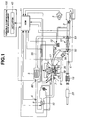
- FIG.1 is a system configuration of an internal combustion engine having a variable compression ratio mechanism according to one exemplary embodiment of the present invention.
- FIG. 2 is an assembled view of the variable compression ratio mechanism of FIG. 1.
- FIG. 3 is a diagram showing a compression ratio characteristic of the engine of FIG. 1.
- FIG. 4 is a diagram showing piston movements in high and low compression ratio states.
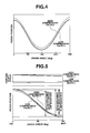
- FIG. 5 is a diagram showing a piston movement at the time of shifting from a high compression ratio state to a low compression ratio state during a piston intake stroke.
- FIG. 6 is a diagram showing a fuel injection characteristic of the engine of FIG. 1.
- FIG. 7 is a fuel injection amount correction map according to a first embodiment of the present invention.
- FIG. 8 is a flowchart for correction of a fuel injection amount according to the first embodiment of the present invention.
- FIG. 9 is a fuel injection amount correction map according to a second embodiment of the present invention.
- FIG. 10 is a flowchart for correction of a fuel injection amount according to the second embodiment of the present invention.
- FIG. 11 is a fuel injection amount correction map according to a third embodiment of the present invention.
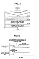
- FIG. 12 is a flowchart for correction of a fuel injection amount according to the third embodiment of the present invention.
- FIG. 13 is a diagram showing a secular change in the deviation between an actual compression ratio and a target compression ratio of the engine.
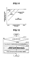
- FIG. 14 is a compression ratio control speed regulation map according to a fourth embodiment of the present invention.
- FIG. 15 is a flowchart for regulation of a compression ratio control speed according to the fourth embodiment of the present invention.
- internal combustion engine 1 has intake pipe 55, exhaust pipe 54, compressor 53, air flow meter 2, intercooler 3, intake pressure gauge 4, turbocharger (supercharger) 51, turbine 52, fuel injection valve 16, spark plug 17, piston 38, cylinder 39, crankshaft 31 (see FIG. 2), catalytic converter 19, muffler 20, engine control module (ECM) 11 and various sensors.
- Compressor 53 is disposed in intake pipe 55.
- Air flow meter 2 is located at an upstream side of compressor 53 to detect an intake gas amount.
- Intercooler 3 is located at a downstream side of compressor 53, and intake pressure gauge 4 is located at a downstream side of intercooler 3 to detect a boost pressure.
- the installed sensors include crank angle sensor 5 to detect a crank angle and an engine speed Ne, oxygen sensor 6 to detect the concentration of oxygen in exhaust gas, knock sensor 8 to detect the occurrence of knocking, throttle sensor 10 to detect an opening of throttle valve 9 (hereinafter referred to as a "throttle valve opening TVO") and intake temperature sensor 60 to detect the temperature of intake gas at an outlet side of intercooler 3.
- Turbine 52 is disposed in exhaust pipe 54.
- Turbocharger 51 is located concentrically to both of turbine 52 and compressor 53, and has exhaust bypass valve 56 to bypass a part of the exhaust gas from an upstream side of turbine 52 so as to control the boost pressure in accordance with the engine operating conditions.
- Fuel injection valve 16 is disposed on each cylinder 39 to inject fuel into an intake port of cylinder 39 and thereby form an air-fuel mixture in a combustion chamber. In the first embodiment, the fuel is injected during an exhaust stroke and an intake stroke of piston 38 in every cycle. The air-fuel mixture is ignited by spark plug 17 to cause combustion in the combustion chamber.
- the combustion exhaust gas flows through exhaust pipe 54 to give a rotational energy to turbine 52.
- the exhaust gas is cleaned by catalytic converter 19, and then, the cleaned gas is discharged through muffler 20.
- engine 1 is designed as a four-cylinder engine and has three other sets of pistons 38, cylinders 39, fuel injection valves 16 and spark plugs 17 although not shown in FIG. 1.
- each piston 38 is given a number (see FIG. 6).
- internal combustion engine 1 has variable compression ratio mechanism 100 to control an engine compression ratio ⁇ .
- variable compression ratio mechanism 100 is coupled to crankshaft 31 and includes lower link 34, upper link 35 and control link 40 for each cylinder 39, control shaft 42 and actuator 43.
- Crankshaft 31 has a plurality of journals 32, crankpins 33 and counterweight 31a. Journals 32 are rotatably supported on the main bearings of an engine cylinder block (not shown). Each crankpin 33 is located eccentrically to journal 32 by a given amount. An engagement hole is formed in substantially the center of lower link 34, and crankpin 33 is engaged in the engagement hole of lower link 34 such that lower link 34 can pivot about crankpin 33.
- Upper link 35 is pivotally connected at a lower end thereof to one end of lower link 24 by connecting pin 36 and is pivotally connected at an upper end thereof to piston 38 by piston pin 37. Piston 38, when subjected to a combustion pressure, develops a reciprocating motion in cylinder 39.
- Control link 40 is pivotally connected at an upper end thereof to the other end of lower link 34 by connecting pin 41 and is pivotally connected at a lower end thereof to an engine body e.g. an appropriate portion of the cylinder block via control shaft 42.
- Control shaft 42 has small-diameter portion 42b and large-diameter portion 42a eccentric to small-diameter portion 42b, and is supported on the engine body so that control shaft 42 can rotate about small-diameter portion 42b while being connected at large-diameter portion 42a to the lower end of control link 40.
- control shaft 42 When control shaft 42 is rotated by means of actuator 43, the shaft center of large-diameter portion 42a relative to the engine body becomes shifted so as to displace the pivot point of control link 40 (i.e. the lower end of control link 40) and thereby change the position of piston 38 at piston top dead center (TDC).
- TDC piston top dead center
- variable compression ratio mechanism 100 is in the form of a multi-link type piston stroke mechanism as described above.
- the multi-link type piston stroke mechanism has the advantage that the knock resistance of engine 1 becomes relatively stable against a change in the compression ratio ⁇ because the engine combustion chamber does not get distorted even when the compression ratio ⁇ is low and does not have edge and point that can cause surface ignition.
- variable compression ratio mechanism 100 may be in the form of a sub-piston type piston stroke mechanism as disclosed in Japanese Patent Publication No. 7-3201.
- the compression ratio ⁇ is controlled in accordance with the engine speed Ne and the throttle valve opening TVO (i.e. engine load).
- ECU 11 sets a target compression ratio so that variable compression ratio mechanism 100 adjusts an actual compression ratio to the target compression ratio.
- the target compression ratio is set to increase with decrease in the throttle valve opening TVO so as to obtain an improvement in fuel economy, and to decrease with increase in the throttle valve opening TVO so as to prevent the occurrence of knocking.
- the throttle valve opening TVO is used as an engine load parameter in the first embodiment, the accelerator pedal opening APO or intake gas amount may be used in place of the throttle valve opening TVO.
- the target compression ratio is set to increase with the engine speed Ne. As the high-speed running of engine 1 develops a larger inertial force, it is alternatively possible to keep the target compression ratio constant when the engine speed Ne is relatively high.
- the target compression ratio is converted into a target angle (position) of control shaft 42 (hereinafter referred to as a "target control shaft angle").
- target control shaft angle a target angle (position) of control shaft 42
- ECU 11 Upon receipt of input about an actual control shaft angle from a control shaft angle sensor (not shown), ECU 11 generates a feedback control signal based on a deviation between the actual control shaft angle and the target control shaft angle and drives actuator 43 under the control signal.
- the piston displacement volume transiently increases compared to the case where the compression ratio ⁇ is kept constant.
- Such an increase in the piston displacement volume causes an increase in the amount of intake gas introduced into cylinder 39 in that cycle. If the fuel injection amount has been decided before the increase in the piston displacement volume, the actual air-fuel ratio of engine 1 deviates from a target air-fuel ratio toward a lean side.
- the piston displacement volume transiently decreases at the time of shifting from a low compression ratio state to a high compression ratio state. If the fuel injection amount has been decided before the decrease in the piston displacement volume, the actual air-fuel ratio of engine 1 deviates from the target air-fuel ratio toward a rich side.
- fuel injection is controlled as follows.
- the fuel is injected in two steps per cylinder per cycle.
- Main fuel injection is performed on the exhaust stroke to inject a standard amount of fuel into the intake port of cylinder 39.
- secondary fuel injection is performed on the intake stroke to inject an adjustable amount of fuel into the intake port of cylinder 30.
- the amount of fuel injected during the intake stroke is referred to as an "intake-stroke fuel injection amount.
- the intake-stroke fuel injection amount is corrected in response to the change in the compression ratio ⁇ in such a manner that the intake-stroke fuel injection amount increases with decrease in the compression ratio ⁇ and decreases with increase in the compression ratio ⁇ .
- the intake-stroke fuel injection amount is corrected by determining a correction value with reference to a fuel injection amount correction map of FIG. 7 that defines the correction value relative to the engine speed Ne and the rotation speed of control shaft 42 (hereinafter referred to as a "control shaft speed Vcsft").
- the control shaft speed Vcsft corresponds to a compression ratio control speed at which the compression ratio ⁇ is changed.
- the correction value is set at a positive value when control shaft 42 rotates in a direction that decreases the compression ratio ⁇ and is set at a negative value when control shaft 42 rotates in a direction that increases the compression ratio ⁇ . Further, the amount of change in the piston displacement volume per cycle decreases with increase in the engine speed Ne when the compression ratio control speed is kept constant, and decreases with decrease in the compression ratio control speed when the engine speed Ne is kept constant. The correction value is thus set in such a manner that the absolute magnitude of the correction value increases with decrease in the engine speed Ne and with increase in the control shaft speed Vcsft.
- the correction of the intake-stroke fuel injection amount is carried out as indicated in FIG. 8.
- step S101 ECM 11 reads the engine speed Ne and the control shaft speed Vcsft in response to the change in the compression ratio ⁇ .
- ECM 11 refers to the fuel injection amount correction map and looks up the correction value in the correction map in correspondence with the engine speed Ne and the control shaft speed Vcsft.
- step S103 ECM 11 corrects the intake-stroke fuel injection amount based on the correction value to thereby adjust a fuel injection pulse width.
- the intake-stroke fuel injection amount is corrected by adding the correction value to a reference fuel amount. If the correction value is zero, the intake-stroke fuel injection amount is set at the reference fuel amount. If the correction value is greater than zero, the intake-stroke fuel injection amount increases by the correction value with respect to the reference fuel amount so as to be commensurate with the transient increase in the piston displacement volume. If the correction value is smaller than zero, the intake-stroke fuel injection amount decreases by the correction value with respect to the reference fuel amount so as to be commensurate with the transient decrease in the piston displacement volume
- the intake-stroke fuel injection amount can be corrected based on not only the first-mentioned correction value set in response to the transient change in the piston displacement volume but also a second correction value set to control the air-fuel ratio to a desired value.
- the second correction value is set to increase the fuel injection amount such that the air-fuel ratio becomes richer when the compression ratio ⁇ decreases and to decrease the fuel injection amount such that the air-fuel ratio becomes leaner when the compression ratio ⁇ increases.
- the intake-stroke fuel injection amount is corrected in response to the change in the piston displacement volume when the control shaft speed Vcsft is larger than or equal to a given value Vcsft1 and the engine speed Ne is lower than or equal to a given value nl. Further, the fuel injection amount correction value is determined based on the compression ratio control speed, i.e., the control shaft speed Vcsft in the second embodiment.
- engine 1 has a displacement volume of 500 cc and a variable compression ratio ⁇ ranging from 8 to 15 and needs 0.1 second to change from the highest compression ratio to the lowest compression ratio (or change from the lowest compression ratio to the highest compression ratio).
- the compression ratio ⁇ changes by the maximum amount between the highest compression ratio and the lowest compression ratio during a single rotation. That is, the compression ratio ⁇ changes during the intake stroke by a half of the above maximum compression ratio change amount. At that time, the amount of change in the piston displacement volume during the intake stroke becomes approximately 17 cc and corresponds to 3.5% of the piston displacement volume.
- the amount of change in the compression ratio ⁇ during the intake stroke increases with increase in the compression ratio control speed. Then, the need for correcting the intake-stroke fuel injection amount increases so as to prevent the air-fuel ratio deviation. It is also reasonable to define, with reference to the minimum compression ratio control speed (at which the intake stroke is longest) , a threshold compression ratio control speed that leads to the air-fuel ratio deviation to be corrected and correct the intake-stroke fuel injection amount when the compression ratio control speed is higher than or equal to the threshold compression ratio control speed.
- the air-fuel deviation is more susceptible to the compression ratio control speed.
- the correction value can be thus determined based on the compression ratio control speed in the second embodiment.
- the correction of the intake-stroke fuel injection amount is carried out as indicated in FIG. 10.
- step S121 ECU 11 reads the engine speed Ne and the control shaft speed Vcsft.
- step S122 ECU 11 determines whether the control shaft speed Vcsft is larger than or equal to the given value Vcsft1 and the engine speed Ne is lower than or equal to the given value nl. If Yes in step S122, the program goes to step S123. If No in step S122, the program exits without correcting the intake-stroke fuel injection amount.
- ECM 11 refers to the fuel injection amount correction map and looks up the correction value in the correction map in correspondence with the control shaft speed Vcsft.
- step S124 ECM 11 corrects the intake-stroke fuel injection amount based on the correction value.
- engine 1 is supplied with an appropriate amount of fuel.
- the air-fuel ratio deviation can be thus prevented even when the piston displacement volume transiently changes under compression ratio control, thereby attaining improvements in running and exhaust performance.
- the control of engine 1 becomes more simplified in the second embodiment.
- the intake-stroke fuel injection amount can be corrected in the second embodiment based on not only the first-mentioned correction value set in response to the transient change in the piston displacement volume but also a second correction value set to control the air-fuel ratio to a desired value as in the first embodiment.
- the third embodiment is similar to the first embodiment, except for the correction procedure of the intake-stroke fuel injection amount.
- the compression ratio control speed is generally determined in accordance with a deviation ⁇ between the actual compression ratio and the target compression ratio at the initial stage of acceleration (hereinafter just referred to as a "compression ratio deviation").
- the correction value is thus set based on the engine speed Ne and the compression ratio deviation ⁇ in the third embodiment, so as to make substantially the same correction as in the first embodiment.
- the correction value is determined with reference to a fuel injection amount correction map of FIG. 11 in the third embodiment. As indicated in the correction map, the correction value is set to increase with decrease in the engine speed Ne and increase with increase in the compression ratio deviation ⁇ .
- FIG. 11 only shows the positive correction value relative to the engine speed Ne and the compression ratio deviation ⁇ at the decrease in the compression ratio ⁇ under acceleration, it is possible to set the negative correction value relative to the engine speed Ne and the compression ratio deviation ⁇ at the increase in the compression ratio ⁇ under deceleration such that the absolute magnitude of the correction value increases with decrease in the engine speed Ne and increases with increase in the compression ratio deviation ⁇ .
- the correction of the intake-stroke fuel injection amount is carried out as indicated in FIG. 12.
- step S131 ECU 11 determines whether engine 1 is in an acceleration state. If Yes in Step S131, the program goes to step S132. If No in step S131, the program exits.
- step S132 ECU 11 calculates the compression ratio deviation ⁇ .
- the compression ratio deviation ⁇ can be determined as a deviation between the actual control shaft angle and the target control shaft angle.
- step S133 ECU 11 refers to the fuel injection amount correction map to look up the correction value in the correction map in correspondence with the engine speed Ne and the compression ratio deviation ⁇ .
- step S134 ECU 11 corrects the intake-stroke fuel injection amount based on the correction value.
- the air-fuel ratio deviation can be thus prevented even when the piston displacement volume transiently changes under compression ratio control, thereby attaining improvements in running and exhaust performance.
- the compression ratio control speed i.e., control shaft speed Vcsft is not necessarily detected to correct the fuel injection amount. This makes it possible to easily make a judgment about whether the fuel injection amount needs correction or not at a relatively early stage without being affected by noises resulting from the detection of the control shaft speed Vcsft and thereby prevent a deterioration in driveability due to the air-fuel ratio deviation more effectively.
- the intake-stroke fuel injection amount may alternatively be corrected in the third embodiment based on not only the first-mentioned correction value set in response to the transient change in piston displacement volume but also a second correction value set to control the air-fuel ratio to a desired value.
- the intake-stroke fuel injection amount is corrected in response to the transient change in the piston displacement volume under compression ratio control in the first to third embodiments.
- the amount of such a transient change in the piston displacement volume can be reduced by regulating the compression ratio control speed (i.e. control shaft speed Vcsft).
- the compression ratio control speed is regulated in accordance with the engine speed Ne and the compression ratio deviation ⁇ in the fourth embodiment so as to prevent the air-fuel ratio deviation under compression ratio control.
- the compression ratio control speed is regulated by determining a regulation value with reference to a compression ratio control speed regulation map of FIG. 14. As indicated in the regulation map, the regulation value is set to increase with decrease in the engine speed Ne and to increase with increase in the compression ratio deviation ⁇ .
- a larger regulation value means that the maximum compression ratio control speed is regulated to a lower value.
- FIG. 14 only shows the regulation value relative to the engine speed Ne and the compression ratio deviation ⁇ at the decrease in the compression ratio ⁇ under acceleration, it is also possible to set the regulation value relative to the engine speed Ne and the compression ratio deviation ⁇ at the increase in the compression ratio ⁇ under deceleration.
- the compression ratio control speed is regulated as indicated in FIG. 15.
- step S141 ECU 11 determines whether engine 1 is in an acceleration state. If Yes in step S141, the program goes to step S142. If No in step S141, the program exits.
- step S142 ECU 11 calculates the compression ratio deviation ⁇ .
- the compression ratio deviation ⁇ can be determined as a deviation between the actual control shaft angle and the target control shaft angle.
- step S143 ECU 11 refers to the compression ratio control speed regulation map and looks up the regulation value in the regulation map in correspondence with the engine speed Ne and the compression ratio deviation ⁇ .
- step S144 ECU 11 regulates the actuator control signal based on the regulation value so as to control the compression ratio control speed.
- the transient change in the piston displacement volume under compression ratio control can be thus minimized so as to prevent the air-fuel deviation and thereby avoid a deterioration in the running and exhaust performance of engine 1.
- the regulation value is set to regulate the control shaft speed Vcsft in the fourth embodiment
- the regulation value may alternatively be set to regulate the maximum current amount when engine 1 is configured to control the compression ratio ⁇ by current regulation, or to regulate the maximum duty ratio when engine 1 is configured to control the compression ratio ⁇ by regulating the duty solenoid of a hydraulic circuit.
- the compression ratio control speed can be regulated based on not only the above-mentioned regulation value set in response to the transient change in piston displacement volume but also a second regulation value set to control the air-fuel ratio to a desired value.
Landscapes
- Engineering & Computer Science (AREA)
- Chemical & Material Sciences (AREA)
- Combustion & Propulsion (AREA)
- Mechanical Engineering (AREA)
- General Engineering & Computer Science (AREA)
- Output Control And Ontrol Of Special Type Engine (AREA)
- Combined Controls Of Internal Combustion Engines (AREA)
- Fuel-Injection Apparatus (AREA)
- Electrical Control Of Air Or Fuel Supplied To Internal-Combustion Engine (AREA)
Abstract
Description
Claims (17)
- An internal combustion engine comprising a variable compression ratio mechanism operatable during an intake stroke to change an actual compression ratio of the engine, the engine being capable of correcting an amount of fuel injected into the engine in response to a change in the compression ratio.
- An internal combustion engine according to Claim 1, wherein the amount of fuel injected into the engine is corrected so as to increase with decrease in the compression ratio.
- An internal combustion engine according to Claim 1 or 2, wherein the amount of fuel injected into the engine is corrected so as to decrease with increase in the compression ratio.
- An internal combustion engine according to any one of Claims 1 to 3, wherein the engine sets a correction value in accordance with an engine speed and a compression ratio control speed to correct the amount of fuel injected into the engine based on the correction value.
- An internal combustion engine according to any one of Claims 1 to 3, wherein the engine sets a correction value in accordance with an engine speed and a deviation between the actual compression ratio and a target compression ratio to correct the amount of fuel injected into the engine based on the correction value.
- An internal combustion engine according to any one of Claims 1 to 3, wherein the engine corrects the amount of fuel injected into the engine when an engine speed is lower than or equal to a first given value and a compression ratio control speed is higher than or equal to a second given value.
- An internal combustion engine according to Claim 6, wherein the engine sets a correction value in accordance with the compression ratio control speed to correct the amount of fuel injected into the engine based on the correction value.
- An internal combustion engine according to any one of Claims 1 to 7, further comprising:a cylinder having an intake port;a fuel injection valve to inject fuel into the intake port of the cylinder during an exhaust stroke and the intake stroke, the fuel being injected in a first fuel amount during the exhaust stroke and in a second fuel amount during the intake stroke; anda control module to control the fuel injection valve so as to correct the second fuel amount in response to the change in the compression ratio.
- An internal combustion engine comprising a variable compression ratio mechanism operatable during an intake stroke to change an actual compression ratio of the engine, the engine being capable of regulating a compression ratio control speed of the variable compression ratio mechanism.
- An internal combustion engine according to Claim 9, wherein the engine sets a regulation value in accordance with an engine speed and a deviation between the actual compression ratio and a target compression ratio to regulate the compression ratio control speed based on the regulation value.
- A control method for an internal combustion engine, comprising:operating a variable compression ratio mechanism of the engine to change an actual compression ratio;allowing a fuel injection valve of the engine to inject fuel into the engine during exhaust and intake strokes; andcontrolling the fuel injection valve so as to correct the amount of fuel injected into the engine during the intake stroke in response to a change in the compression ratio.
- A control method according to Claim 11, wherein the amount of fuel injected into the engine during the intake stroke is corrected so as to increase with decrease in the compression ratio and decrease with increase in the compression ratio.
- A control method according to Claim 11 or 12, wherein said controlling comprises setting a correction value in accordance with an engine speed and a compression ratio control speed to correct the amount of fuel injected into the engine during the intake stroke based on the correction value.
- A control method according to Claim 11 or 12, wherein said controlling comprises setting a correction value in accordance with an engine speed and a deviation between the actual compression ratio and a target compression ratio to correct the amount of fuel injected into the engine during the intake stroke based on the correction value.
- A control method according to Claim 11 or 12, wherein said controlling comprises:determining whether an engine speed is lower than or equal to a first given value and a compression ratio control speed is higher than or equal to a second given value; andwhen the engine speed is lower than or equal to the first given value and the compression ratio control speed is higher than or equal to the second given value, setting a correction value in accordance with the compression ratio control speed to correct the amount of fuel injected into the engine during the intake stroke based on the correction value.
- A control method for an internal combustion engine, comprising:operating a variable compression ratio mechanism of the engine to change an actual compression ratio; andregulating a compression ratio control speed of the variable compression ratio mechanism in response to a change in the compression ratio.
- A control method according to Claim 16, wherein said regulating comprises setting a regulation value in accordance with an engine speed and a deviation between the actual compression ratio and a target compression ratio to regulate the compression ratio control speed based on the regulation value.
Applications Claiming Priority (2)
| Application Number | Priority Date | Filing Date | Title |
|---|---|---|---|
| JP2002382130 | 2002-12-27 | ||
| JP2002382130A JP4175110B2 (en) | 2002-12-27 | 2002-12-27 | Internal combustion engine with variable compression ratio mechanism |
Publications (3)
| Publication Number | Publication Date |
|---|---|
| EP1433938A2 true EP1433938A2 (en) | 2004-06-30 |
| EP1433938A3 EP1433938A3 (en) | 2004-09-01 |
| EP1433938B1 EP1433938B1 (en) | 2006-04-12 |
Family
ID=32463664
Family Applications (1)
| Application Number | Title | Priority Date | Filing Date |
|---|---|---|---|
| EP03029075A Expired - Lifetime EP1433938B1 (en) | 2002-12-27 | 2003-12-17 | Internal combustion engine having variable compression ratio mechanism and control method therefor |
Country Status (5)
| Country | Link |
|---|---|
| US (1) | US6990934B2 (en) |
| EP (1) | EP1433938B1 (en) |
| JP (1) | JP4175110B2 (en) |
| CN (1) | CN1313720C (en) |
| DE (1) | DE60304551T2 (en) |
Cited By (4)
| Publication number | Priority date | Publication date | Assignee | Title |
|---|---|---|---|---|
| WO2012139609A1 (en) | 2011-04-15 | 2012-10-18 | Daimler Ag | Method for operating an adjustment device for variably adjusting a compression ration of an internal combustion engine |
| JP2013241845A (en) * | 2012-05-18 | 2013-12-05 | Nissan Motor Co Ltd | Variable compression ratio internal combustion engine |
| CN101550875B (en) * | 2008-03-31 | 2014-01-08 | 现代自动车株式会社 | Variable compression ratio apparatus |
| EP1911952A3 (en) * | 2006-10-11 | 2016-03-23 | Nissan Motor Co., Ltd. | Internal combustion engine |
Families Citing this family (24)
| Publication number | Priority date | Publication date | Assignee | Title |
|---|---|---|---|---|
| JP2006046193A (en) * | 2004-08-05 | 2006-02-16 | Nissan Motor Co Ltd | Control device for internal combustion engine |
| JP4600074B2 (en) * | 2005-02-15 | 2010-12-15 | 日産自動車株式会社 | Variable compression ratio device for internal combustion engine |
| JP4657162B2 (en) * | 2006-07-10 | 2011-03-23 | 本田技研工業株式会社 | Variable compression ratio device for internal combustion engine |
| JP5118839B2 (en) * | 2006-10-31 | 2013-01-16 | 日産自動車株式会社 | In-cylinder direct injection internal combustion engine |
| JP4450024B2 (en) * | 2007-07-12 | 2010-04-14 | トヨタ自動車株式会社 | Spark ignition internal combustion engine |
| JP5332645B2 (en) * | 2008-03-03 | 2013-11-06 | 日産自動車株式会社 | In-cylinder direct injection internal combustion engine |
| JP5126410B2 (en) * | 2009-02-20 | 2013-01-23 | トヨタ自動車株式会社 | Spark ignition internal combustion engine |
| JP4962580B2 (en) * | 2010-02-24 | 2012-06-27 | 日産自動車株式会社 | Control device for internal combustion engine |
| JP5782680B2 (en) * | 2010-05-19 | 2015-09-24 | 日産自動車株式会社 | Control device for internal combustion engine |
| JP5585521B2 (en) * | 2011-04-13 | 2014-09-10 | トヨタ自動車株式会社 | Internal combustion engine having a variable compression ratio mechanism |
| WO2012160724A1 (en) | 2011-05-23 | 2012-11-29 | トヨタ自動車株式会社 | Internal combustion engine with variable compression ratio mechanism |
| JP5206856B2 (en) * | 2011-10-31 | 2013-06-12 | 日産自動車株式会社 | Control device for internal combustion engine |
| US20160222895A1 (en) * | 2011-12-16 | 2016-08-04 | General Electric Company | Multi-fuel system and method |
| US9429095B2 (en) * | 2012-06-11 | 2016-08-30 | International Engine Intellectual Property Company, Llc. | System and method of controlling fuel injection droplet size in an engine having an in cylinder pressure |
| JP5971396B2 (en) * | 2013-02-22 | 2016-08-17 | 日産自動車株式会社 | Control device and control method for internal combustion engine |
| US9422873B2 (en) * | 2013-12-12 | 2016-08-23 | Ford Global Technologies, Llc | Methods and systems for operating an engine |
| US9890716B2 (en) * | 2015-01-23 | 2018-02-13 | Ford Global Technologies, Llc | Method and system for pre-ignition control |
| US10202898B2 (en) | 2017-04-25 | 2019-02-12 | Ford Global Technologies, Llc | Method and system for fuel injection control |
| CN106958550B (en) * | 2017-05-18 | 2018-04-20 | 重庆交通大学 | VCR engine crankshaft connecting rod hydraulic control systems and its control method |
| KR20190018822A (en) * | 2017-08-16 | 2019-02-26 | 현대자동차주식회사 | Variable compression ratio device, and the control method thereof |
| KR102406127B1 (en) * | 2017-10-16 | 2022-06-07 | 현대자동차 주식회사 | Variable compression ratio engine |
| WO2020140843A1 (en) * | 2018-12-30 | 2020-07-09 | 长城汽车股份有限公司 | Variable compression ratio mechanism, engine and automobile |
| US11092089B1 (en) * | 2020-06-30 | 2021-08-17 | GM Global Technology Operations LLC | Variable compression ratio engine control strategy |
| CN114790941A (en) * | 2021-01-26 | 2022-07-26 | 长城汽车股份有限公司 | Method and device for controlling position of eccentric shaft of variable compression ratio mechanism |
Family Cites Families (8)
| Publication number | Priority date | Publication date | Assignee | Title |
|---|---|---|---|---|
| JPS60230526A (en) * | 1984-04-27 | 1985-11-16 | Mazda Motor Corp | Variable compression-ratio type engine |
| JPH0692746B2 (en) * | 1984-04-27 | 1994-11-16 | マツダ株式会社 | Variable compression ratio engine |
| JPH073201B2 (en) | 1985-10-01 | 1995-01-18 | トヨタ自動車株式会社 | Mechanical supercharged engine with variable compression ratio device |
| EP0387372B1 (en) * | 1989-03-14 | 1994-05-25 | Vasant Mukund Joshi | Improvements in reciprocating piston internal combustion engines and like machines |
| US6125801A (en) * | 1997-11-25 | 2000-10-03 | Mendler; Edward Charles | Lean-burn variable compression ratio engine |
| JP3991550B2 (en) | 2000-03-21 | 2007-10-17 | 日産自動車株式会社 | Internal combustion engine with variable compression ratio mechanism |
| ATE371103T1 (en) * | 2000-11-29 | 2007-09-15 | Kenneth W Cowans | HIGH PERFORMANCE ENGINE WITH VARIABLE COMPRESSION RATIO AND VARIABLE CHARGE (VCRC ENGINE) |
| US6394048B1 (en) * | 2001-01-16 | 2002-05-28 | Ford Global Technologies, Inc. | Variable compression ratio internal combustion engine using field-sensitive fluid |
-
2002
- 2002-12-27 JP JP2002382130A patent/JP4175110B2/en not_active Expired - Fee Related
-
2003
- 2003-12-08 US US10/728,900 patent/US6990934B2/en not_active Expired - Lifetime
- 2003-12-17 EP EP03029075A patent/EP1433938B1/en not_active Expired - Lifetime
- 2003-12-17 DE DE60304551T patent/DE60304551T2/en not_active Expired - Lifetime
- 2003-12-26 CN CNB2003101244414A patent/CN1313720C/en not_active Expired - Lifetime
Cited By (5)
| Publication number | Priority date | Publication date | Assignee | Title |
|---|---|---|---|---|
| EP1911952A3 (en) * | 2006-10-11 | 2016-03-23 | Nissan Motor Co., Ltd. | Internal combustion engine |
| CN101550875B (en) * | 2008-03-31 | 2014-01-08 | 现代自动车株式会社 | Variable compression ratio apparatus |
| WO2012139609A1 (en) | 2011-04-15 | 2012-10-18 | Daimler Ag | Method for operating an adjustment device for variably adjusting a compression ration of an internal combustion engine |
| DE102011017185A1 (en) | 2011-04-15 | 2012-10-18 | Daimler Ag | Method for operating an adjusting device of an internal combustion engine |
| JP2013241845A (en) * | 2012-05-18 | 2013-12-05 | Nissan Motor Co Ltd | Variable compression ratio internal combustion engine |
Also Published As
| Publication number | Publication date |
|---|---|
| DE60304551D1 (en) | 2006-05-24 |
| CN1512050A (en) | 2004-07-14 |
| EP1433938B1 (en) | 2006-04-12 |
| JP2004211598A (en) | 2004-07-29 |
| EP1433938A3 (en) | 2004-09-01 |
| CN1313720C (en) | 2007-05-02 |
| JP4175110B2 (en) | 2008-11-05 |
| US20040123818A1 (en) | 2004-07-01 |
| DE60304551T2 (en) | 2006-08-24 |
| US6990934B2 (en) | 2006-01-31 |
Similar Documents
| Publication | Publication Date | Title |
|---|---|---|
| EP1433938B1 (en) | Internal combustion engine having variable compression ratio mechanism and control method therefor | |
| US6915784B2 (en) | System and method for controlling spark-ignition internal combustion engine | |
| US6691022B2 (en) | Intake air quantity measurement for internal combustion engine | |
| US6516757B2 (en) | Internal combustion engine with a supercharger and an improved piston crank mechanism | |
| CN103874839B (en) | Apparatus and method for controlling speed of internal combustion engine | |
| US8818687B2 (en) | Control apparatus of internal combustion engine | |
| US7082898B2 (en) | Internal combustion engine of compression ignition type | |
| US6581564B2 (en) | Ignition time controller, ignition time control method and engine control unit for internal combustion engine | |
| US7328673B2 (en) | Valve timing correction control apparatus and method for an internal combustion engine | |
| US7121238B2 (en) | Intake valve control system and method for internal combustion engine | |
| JP4438368B2 (en) | Control device for variable compression ratio engine | |
| CN110730861B (en) | Method and device for controlling internal combustion engine | |
| JP4277623B2 (en) | Ignition timing control device for internal combustion engine with variable compression ratio mechanism | |
| JP4400116B2 (en) | Ignition control device for internal combustion engine with variable compression ratio mechanism | |
| JP6941652B2 (en) | Supercharging pressure setting device | |
| JP2004316545A (en) | Cylinder control device for compression ignition type internal combustion engine | |
| JP6870350B2 (en) | Internal combustion engine control device | |
| JP2007132217A (en) | Combustion control device for compression ignition engine | |
| JP2005139986A (en) | Combustion control method for gasoline self-ignition engine | |
| JP2005030253A (en) | Control device for internal combustion engine with variable compression ratio mechanism | |
| JP7767980B2 (en) | Homogeneous charge compression ignition internal combustion engine and control method thereof | |
| JP7439655B2 (en) | Engine control method and control device | |
| WO2019058728A1 (en) | Internal combustion engine control device and internal combustion engine control method | |
| JP2009127485A (en) | Internal combustion engine |
Legal Events
| Date | Code | Title | Description |
|---|---|---|---|
| PUAI | Public reference made under article 153(3) epc to a published international application that has entered the european phase |
Free format text: ORIGINAL CODE: 0009012 |
|
| 17P | Request for examination filed |
Effective date: 20031217 |
|
| AK | Designated contracting states |
Kind code of ref document: A2 Designated state(s): AT BE BG CH CY CZ DE DK EE ES FI FR GB GR HU IE IT LI LU MC NL PT RO SE SI SK TR |
|
| AX | Request for extension of the european patent |
Extension state: AL LT LV MK |
|
| PUAL | Search report despatched |
Free format text: ORIGINAL CODE: 0009013 |
|
| AK | Designated contracting states |
Kind code of ref document: A3 Designated state(s): AT BE BG CH CY CZ DE DK EE ES FI FR GB GR HU IE IT LI LU MC NL PT RO SE SI SK TR |
|
| AX | Request for extension of the european patent |
Extension state: AL LT LV MK |
|
| 17Q | First examination report despatched |
Effective date: 20050316 |
|
| AKX | Designation fees paid |
Designated state(s): DE FR GB |
|
| RBV | Designated contracting states (corrected) |
Designated state(s): DE FR GB |
|
| GRAP | Despatch of communication of intention to grant a patent |
Free format text: ORIGINAL CODE: EPIDOSNIGR1 |
|
| GRAS | Grant fee paid |
Free format text: ORIGINAL CODE: EPIDOSNIGR3 |
|
| GRAA | (expected) grant |
Free format text: ORIGINAL CODE: 0009210 |
|
| AK | Designated contracting states |
Kind code of ref document: B1 Designated state(s): DE FR GB |
|
| REG | Reference to a national code |
Ref country code: GB Ref legal event code: FG4D |
|
| RIN1 | Information on inventor provided before grant (corrected) |
Inventor name: SUGIYAMA, TAKANOBU Inventor name: TAKEMURA, SHINICHI,KANAZAWAHAKKEIKOPORASU 410, Inventor name: HIYOSHI, RYOSUKE Inventor name: AOYAMA, SHUNICHI |
|
| REF | Corresponds to: |
Ref document number: 60304551 Country of ref document: DE Date of ref document: 20060524 Kind code of ref document: P |
|
| ET | Fr: translation filed | ||
| PLBE | No opposition filed within time limit |
Free format text: ORIGINAL CODE: 0009261 |
|
| STAA | Information on the status of an ep patent application or granted ep patent |
Free format text: STATUS: NO OPPOSITION FILED WITHIN TIME LIMIT |
|
| 26N | No opposition filed |
Effective date: 20070115 |
|
| REG | Reference to a national code |
Ref country code: FR Ref legal event code: PLFP Year of fee payment: 13 |
|
| REG | Reference to a national code |
Ref country code: FR Ref legal event code: PLFP Year of fee payment: 14 |
|
| REG | Reference to a national code |
Ref country code: FR Ref legal event code: PLFP Year of fee payment: 15 |
|
| PGFP | Annual fee paid to national office [announced via postgrant information from national office to epo] |
Ref country code: FR Payment date: 20230119 Year of fee payment: 20 |
|
| PGFP | Annual fee paid to national office [announced via postgrant information from national office to epo] |
Ref country code: GB Payment date: 20230120 Year of fee payment: 20 Ref country code: DE Payment date: 20230119 Year of fee payment: 20 |
|
| REG | Reference to a national code |
Ref country code: DE Ref legal event code: R071 Ref document number: 60304551 Country of ref document: DE |
|
| REG | Reference to a national code |
Ref country code: GB Ref legal event code: PE20 Expiry date: 20231216 |
|
| PG25 | Lapsed in a contracting state [announced via postgrant information from national office to epo] |
Ref country code: GB Free format text: LAPSE BECAUSE OF EXPIRATION OF PROTECTION Effective date: 20231216 |
|
| PG25 | Lapsed in a contracting state [announced via postgrant information from national office to epo] |
Ref country code: GB Free format text: LAPSE BECAUSE OF EXPIRATION OF PROTECTION Effective date: 20231216 |