JP7439655B2 - Engine control method and control device - Google Patents
Engine control method and control device Download PDFInfo
- Publication number
- JP7439655B2 JP7439655B2 JP2020099942A JP2020099942A JP7439655B2 JP 7439655 B2 JP7439655 B2 JP 7439655B2 JP 2020099942 A JP2020099942 A JP 2020099942A JP 2020099942 A JP2020099942 A JP 2020099942A JP 7439655 B2 JP7439655 B2 JP 7439655B2
- Authority
- JP
- Japan
- Prior art keywords
- rate
- engine
- maximum
- increase
- cylinder pressure
- Prior art date
- Legal status (The legal status is an assumption and is not a legal conclusion. Google has not performed a legal analysis and makes no representation as to the accuracy of the status listed.)
- Active
Links
Images


Classifications
-
- Y—GENERAL TAGGING OF NEW TECHNOLOGICAL DEVELOPMENTS; GENERAL TAGGING OF CROSS-SECTIONAL TECHNOLOGIES SPANNING OVER SEVERAL SECTIONS OF THE IPC; TECHNICAL SUBJECTS COVERED BY FORMER USPC CROSS-REFERENCE ART COLLECTIONS [XRACs] AND DIGESTS
- Y02—TECHNOLOGIES OR APPLICATIONS FOR MITIGATION OR ADAPTATION AGAINST CLIMATE CHANGE
- Y02T—CLIMATE CHANGE MITIGATION TECHNOLOGIES RELATED TO TRANSPORTATION
- Y02T10/00—Road transport of goods or passengers
- Y02T10/10—Internal combustion engine [ICE] based vehicles
- Y02T10/40—Engine management systems
Landscapes
- Combined Controls Of Internal Combustion Engines (AREA)
Description
本発明は、エンジンの制御方法及び制御装置に関するものである。 The present invention relates to an engine control method and control device.
車両のエンジンの燃焼サイクルにおいて、各気筒の筒内圧が急激に上昇した場合に、ピストンに連結する部材に負荷がかかり、その結果、異音が発生してしまうことがあった。そこで、特許文献1に記載のエンジンの燃焼制御装置は、筒内圧の急激な上昇を抑制するため、各気筒の筒内圧上昇率の最大値とエンジン運転状態に基づいて設定した筒内圧上昇率の許容値と比較して、最大値が許容値を超えた場合に点火時期を遅角補正している。
In the combustion cycle of a vehicle engine, when the in-cylinder pressure of each cylinder increases rapidly, a load is applied to a member connected to a piston, and as a result, abnormal noise may be generated. Therefore, in order to suppress a sudden increase in cylinder pressure, the engine combustion control device described in
エンジンに発生する異音の大きさは、エンジンの運転状態のみならず、筒内圧が急激に上昇する時のクランク角によっても変化する。しかしながら、特許文献1に記載のエンジンの燃焼制御装置では、点火時期を遅角させるか否かの判断に、筒内圧の上昇率が最大となる時のクランク角が考慮されていない。そのため、異音の発生を充分に抑制することができないという問題があった。
The magnitude of abnormal noise generated in an engine varies not only by the operating state of the engine but also by the crank angle at which the cylinder pressure suddenly increases. However, in the engine combustion control device described in
本発明が解決しようとする課題は、筒内圧の急激な上昇に起因する異音の発生を抑制することができるエンジンの制御方法及び制御装置を提供することである。 The problem to be solved by the present invention is to provide an engine control method and a control device that can suppress the generation of abnormal noise caused by a sudden increase in cylinder pressure.
本発明に係るエンジンの制御方法及び制御装置は、筒内圧上昇率が最大となるクランク角及び筒内圧の最大上昇率を算出し、最大上昇率が筒内圧の許容上昇率より大きい場合に、点火時期を遅角させることによって、上記課題を解決する。 The engine control method and control device according to the present invention calculates the crank angle and the maximum rate of increase in cylinder pressure at which the rate of increase in cylinder pressure is maximum, and when the maximum rate of increase is greater than the allowable rate of increase in cylinder pressure, ignition is activated. The above problem is solved by delaying the timing.
本発明によれば、筒内圧の上昇率が最大となる時のクランク角に応じて点火時期を遅角させるため、筒内圧の急激な上昇に起因する異音の発生を抑制することができる。 According to the present invention, since the ignition timing is retarded in accordance with the crank angle at which the rate of increase in cylinder pressure is at its maximum, it is possible to suppress the occurrence of abnormal noise caused by a sudden increase in cylinder pressure.
以下、本発明の実施形態を図面に基づいて説明する。
まず、本実施形態のエンジンシステム1の全体構成について、図1を用いて説明する。
図1に示すように、エンジンシステム1は、内燃機関たるエンジン100を有し、自動車などに搭載される。本例のエンジン100の吸気側は、コレクタ15を介して、吸気通路11に接続されている。また、エンジン100の排気側は、排気通路21に接続されている。エンジンシステム1は、エンジンシステム1の動作を制御する制御装置50(ECU)を有している。なお、本実施形態におけるエンジン100は、圧縮比を変更可能な複リンク式の可変圧縮比エンジンである。エンジン100の各気筒には、燃料噴射バルブ17、及び点火プラグ20が設けられている。なお、図1に示す本例のエンジン100は、過給機30と排気ガス再循環機構40を備えたものであるが、本発明のエンジンの制御方法及び制御装置は、これら過給機30と排気ガス再循環機構40の少なくとも一方を備えないエンジンにも適用することができる。
Embodiments of the present invention will be described below based on the drawings.
First, the overall configuration of an
As shown in FIG. 1, an
本例のエンジン100の吸気通路11には、上流側から下流側に向かって、エアフィルタ12、エアフローメータ13、第1再循環調整バルブ72、過給機30のコンプレッサホイール34、インタークーラ36及びスロットルバルブ14が設けられている。第1再循環調整バルブ72の下流側かつコンプレッサホイール34の上流側には、排気ガス再循環機構40の再循環通路41が接続されている。また、第1再循環調整バルブ72の下流側かつ再循環通路41との接続部の上流側には、吸気圧センサ73が設けられている。また、吸気通路11には、過給機30のコンプレッサホイール34及びインタークーラ36を迂回する環流通路70が接続されている。環流通路70には、環流通路70を開閉する環流バルブ71が設けられている。環流バルブ71は、たとえば、アクセル開度がゼロになってスロットルバルブ14が閉じたときに、制御装置50の指示信号によって開状態となる。これにより、コンプレッサホイール34によって圧縮された吸気は、環流通路70を介して吸気通路11のコンプレッサホイール34の上流側に環流する。
The
本例のエンジン100の排気通路21には、上流側から下流側に向かって、過給機30のタービンホイール32、排気浄化触媒24及びマフラ23が設けられている。なお、排気通路21には、タービンホイール32を迂回する迂回路35が接続されている。迂回路35には、タービンホイール32を迂回する排気ガスの量を調整するためのウェイストゲートバルブ31が設けられている。また、排気通路21の排気浄化触媒24の下流側かつマフラ23の上流側には、排気ガスの圧力を検出する排気圧センサ25が設けられている。さらに、排気圧センサ25の下流側かつマフラ23の上流側には、排気ガス再循環機構40の再循環通路41が接続されている。
In the
再循環通路41には、第2再循環調整バルブ42が設けられている。再循環通路41を介して排気通路21側から吸気通路11側へ再循環する排気ガスの流量は、吸気通路11の第1再循環調整バルブ72及び再循環通路41の第2再循環調整バルブ42によって制御される。
A second
制御装置50は、エアフローメータ13、吸気圧センサ73、排気圧センサ25、アクセル開度センサ26、及びクランク角センサ27からの検出信号を受け取る。また、制御装置50は、スロットルバルブ14、環流バルブ71、第1再循環調整バルブ72、第2再循環調整バルブ42及びウェイストゲートバルブ31の開閉情報を受け取るとともに、これらのバルブの各々の開閉状態を制御する。特に、制御装置50は、運転者のアクセルペダル操作量等に基づき演算される要求トルクを達成するように、スロットルバルブ14、及びウェイストゲートバルブ31の開度を制御して吸気量を調整する。
The
また、エンジン100の燃料噴射バルブ17は、制御装置50において設定される駆動パルス信号によって開弁駆動され、燃料ポンプ(不図示)から圧送されてプレッシャレギュレータ(不図示)により所定圧力に制御された燃料を、エンジン100の燃焼室内に直接または間接的に噴射する。また、エンジン100の点火プラグ20は、制御装置50からの点火信号に基づいて吸入混合気に対して点火を行う。なお、制御装置50による具体的な点火時期の制御については、後述する。
Further, the
次に、エンジン100の具体的な機械的構造について、図2を用いて説明する。
図2に示すように、エンジン100は、例えば直列4気筒エンジンであり、図2は一つの気筒の断面を示している。本発明に係るエンジンは気筒数に限定されず、直列4気筒エンジンのほか、直列3気筒、直列6気筒、V型6気筒、V型8気筒など、公知のエンジンに適用することができる。本実施形態のエンジン100は、ピストン102の上死点位置を変化させて圧縮比を変更するマルチリンク機構101を備える可変圧縮比エンジンである。マルチリンク機構101は、ピストン102とクランクシャフト103とを、アッパリンク104及びロアリンク105で連結している。すなわち、ピストン102は、複数のリンク部材(アッパリンク104,ロアリンク105)を介して、エンジン100のクランクシャフト103に連結されている。また、マルチリンク機構101は、コントロールリンク106によってロアリンク105の姿勢を制御することで圧縮比を変更する。
Next, the specific mechanical structure of the
As shown in FIG. 2, the
アッパリンク104は、その上端においてピストンピン107を介して且つ当該ピストンピン107を中心にしてピストン102に回動可能に連結されている。アッパリンク104は、その下端においてアッパピン108を介して且つ当該アッパピン108を中心にしてロアリンク105の一端に回動可能に連結されている。ロアリンク105の他端は、コントロールピン109を介して且つ当該コントロールピン109を中心にしてコントロールリンク106に回動可能に連結されている。
The
ロアリンク105には、アッパピン108の中心とコントロールピン109の中心との間にクランクピン110が配置されるように、クランクピン110が連結される連結孔111が形成されている。ロアリンク105は、ほぼ中央に連結孔111を有し、後からクランクピン110に組み付けることができるように、図示する上下の2部材から分割可能に構成されている。ロアリンク105は、連結孔111にクランクシャフト103のクランクピン110が挿入されることで、クランクピン110を中心に揺動する。
A connecting hole 111 to which the crank pin 110 is connected is formed in the
クランクシャフト103は、クランクピン110、ジャーナル112及びカウンターウェイト113を備える。クランクピン110の中心110Cは、ジャーナル112の中心(すなわちクランクシャフト103の回転軸中心103C)から所定量偏心している。カウンターウェイト113は、クランクアームに一体形成されて、ピストン運動の回転1次振動成分を低減する。クランクシャフト103は、シリンダブロック116に回転可能に支持されている。
The
コントロールリンク106の上端は、コントロールピン109を介して且つ当該コントロールピン109を中心にロアリンク105に対して回動可能に連結されている。コントロールリンク106の下端は、コントロールシャフト114の偏心軸(揺動軸)115に連結されている。コントロールリンク106は、偏心軸115を中心に揺動する。コントロールシャフト114は、クランクシャフト103と平行(図面の紙面に対して垂直な方向に平行)に配置され、シリンダブロック116に回転自在に支持されている。コントロールシャフト114の偏心軸115は、コントロールシャフト114の軸心から所定量だけ偏心した位置に形成されている。コントロールシャフト114は、ウォーム&ウォームホイール等の機構を介してアクチュエータ117によって回転制御され、これにより偏心軸115を移動させる。
The upper end of the
アクチュエータ117によってコントロールシャフト114が回転し、偏心軸115がコントロールシャフト114の中心軸に対して相対的に低くなる方向に移動すると、ロアリンク105はクランクピン110を中心としてアッパピン108の位置が相対的に上昇する方向に傾く。これによりピストン102の上死点位置が上昇して、エンジン100の幾何学的な圧縮比(ピストン上死点位置での燃焼室容積に対するピストン下死点位置での燃焼室容積の比)が高くなる。これに対して、偏心軸115がコントロールシャフト114の中心軸に対して相対的に高くなる方向に移動すると、ロアリンク105はクランクピン110を中心としてアッパピン108の位置が相対的に低くなる方向に傾く。これによりピストン102の上死点位置が下降して、エンジン100の圧縮比が低くなる。なお実際の有効圧縮比は、上述した幾何学的な圧縮比に加えて、吸気弁の開閉時期によって変動する。
When the
次に、制御装置50による点火時期の制御方法について、図3~8を用いて説明する。
図3に示すように、制御装置50は、運転状態取得部51、クランク角算出部52、筒内圧最大上昇率算出部53、筒内圧許容上昇率算出部54、及び、点火時期制御部55を有する。点火時期制御部55は、異音判定部56、基本点火時期算出部57、及び、点火時期補正部58を有する。制御装置50は、CPU、ROM及びRAMを備えるコンピュータからなり、運転状態取得部51、クランク角算出部52、筒内圧最大上昇率算出部53、筒内圧許容上昇率算出部54、及び、点火時期制御部55は、制御装置50の機能を実行するためのプログラムとしてROMに格納されている。
Next, a method of controlling ignition timing by the
As shown in FIG. 3, the
運転状態取得部51は、各種センサの検出信号等からエンジン100の現在の運転状態を取得する。エンジン100の運転状態とは、具体的には、エンジン100の回転速度、充填効率(エンジンの燃焼に寄与するフレッシュエアーの絶対量)、点火プラグ20の気筒別点火時期、筒内圧が最大となるときのクランク角(Θ‐Pmax)、再循環排気ガスの流量、可変圧縮比(有効圧縮比)、空燃比(A/F)、吸気量、排気量、エンジン100の冷却水温度、吸気温度、吸気圧等である。なお、エンジン100が吸気バルブと排気バルブの開閉タイミングやリフト量を可変とする可変バルブ機構を有する場合は、そのバルブタイミングをエンジンの運転状態の一つとしてもよい。このようなエンジン100の運転状態の取得には、エンジンの一般的な制御に用いられる各種センサの検出信号を共用することができる。
The operating state acquisition unit 51 obtains the current operating state of the
クランク角算出部52は、運転状態取得部51が取得したエンジン100の運転状態に基づいて、エンジン100の各気筒の筒内圧上昇率(dP/dΘ)が最大となるクランク角(Θ‐dP/dΘmax)を算出する。また、筒内圧最大上昇率算出部53は、運転状態取得部51が取得したエンジン100の運転状態に基づいて、各気筒の筒内圧上昇率の最大値(以下、最大上昇率(dP/dΘmax)ともいう)を算出する。
The crank angle calculating section 52 calculates a crank angle (Θ-dP/ dΘmax). Further, the maximum cylinder pressure increase rate calculation unit 53 calculates the maximum value of the cylinder pressure increase rate of each cylinder (hereinafter referred to as maximum rate of increase (dP/dΘmax)) based on the operating state of the
これらクランク角算出部52及び筒内圧最大上昇率算出部53は、具体的には、図5のグラフに示すように、推定した筒内圧とクランク角センサ27の検出値に基づいて、上死点(TDC)を基準としたクランク角(Θ)と筒内圧(P)との関係を算出する。なお、筒内圧は可変バルブ機構のバルブタイミング、可変圧縮比機構の圧縮比、及び吸気圧等から推定するが、筒内圧センサで検出しても構わない。図5のグラフにおいて、筒内圧が上昇して筒内圧最大値(Pmax)に達するクランク角をΘ‐Pmaxとする。クランク角算出部52は、クランク角が上死点(TDC)からΘ‐Pmaxに到るまでの間に、筒内圧上昇率(dP/dΘmax)、すなわち、グラフの接線Tの傾きが最大になるときのクランク角(Θ‐dP/dΘmax)を算出する。また、筒内圧最大上昇率算出部53は、筒内圧(P)の最大上昇率(dP/dΘmax)、すなわち接線Tの傾きの最大値を算出する。なお、筒内圧上昇率(dP/dΘ)が最大となるクランク角(Θ‐dP/dΘmax)や筒内圧(P)の最大上昇率(dP/dΘmax)は、筒内圧最大値(Pmax)、筒内圧が最大となるクランク角(Θ‐Pmax)、及び筒内圧が上昇してから最大値(Pmax)に到達するまでの期間などから算出しているが、これに限らない。 Specifically, as shown in the graph of FIG. 5, the crank angle calculation section 52 and the cylinder pressure maximum increase rate calculation section 53 calculate The relationship between the crank angle (Θ) and the cylinder pressure (P) based on (TDC) is calculated. Note that the cylinder pressure is estimated from the valve timing of the variable valve mechanism, the compression ratio of the variable compression ratio mechanism, the intake pressure, etc., but it may also be detected by a cylinder pressure sensor. In the graph of FIG. 5, the crank angle at which the cylinder pressure increases and reaches the maximum cylinder pressure value (Pmax) is defined as Θ-Pmax. The crank angle calculation unit 52 calculates that the in-cylinder pressure increase rate (dP/dΘmax), that is, the slope of the tangent line T of the graph, becomes maximum during the time when the crank angle reaches Θ-Pmax from top dead center (TDC). The crank angle (Θ-dP/dΘmax) at that time is calculated. Further, the cylinder pressure maximum increase rate calculation unit 53 calculates the maximum increase rate (dP/dΘmax) of the cylinder pressure (P), that is, the maximum value of the slope of the tangent line T. The crank angle (Θ-dP/dΘmax) at which the rate of increase in cylinder pressure (dP/dΘ) is maximum and the maximum rate of increase in cylinder pressure (P) (dP/dΘmax) are determined by the maximum value of cylinder pressure (Pmax) and the maximum rate of increase in cylinder pressure (Pmax). It is calculated from the crank angle (Θ-Pmax) at which the internal pressure is maximum, the period from when the cylinder internal pressure increases until it reaches the maximum value (Pmax), but is not limited thereto.
なお、クランク角(Θ)と筒内圧(P)との関係は、エンジン100の運転状態に応じて異なるため、筒内圧上昇率が最大になるときのクランク角(Θ‐dP/dΘmax)、及び、最大上昇率(dP/dΘmax)は、エンジン100の運転状態に応じて算出される。また、図5に示す例では、筒内圧上昇率(dP/dΘmax)が最大になるときのクランク角(Θ‐dP/dΘmax)は上死点(TDC)よりも後に位置しているが、これに限定されず、上死点(TDC)よりも前のクランク角において筒内圧上昇率(dP/dΘmax)が最大になる場合もある。
Note that the relationship between the crank angle (Θ) and the cylinder pressure (P) differs depending on the operating state of the
図3に戻り、筒内圧許容上昇率算出部54は、筒内圧上昇率(dP/dΘ)が最大となるクランク角(Θ‐dP/dΘmax)における許容上昇率(dPa/dΘ)を算出する。なお、許容上昇率(dPa/dΘ)は、各気筒の筒内圧上昇率(dP/dΘ)の許容値である。 Returning to FIG. 3, the cylinder pressure allowable increase rate calculation unit 54 calculates the allowable increase rate (dPa/dΘ) at the crank angle (Θ-dP/dΘmax) at which the cylinder pressure increase rate (dP/dΘ) is maximum. Note that the allowable rate of increase (dPa/dΘ) is an allowable value for the rate of increase in cylinder pressure (dP/dΘ) of each cylinder.
ここで、エンジン100における異音の発生と、筒内圧上昇率(dP/dΘ)と、クランク角(Θ)との関係について、図6,7の模式図を用いて説明する。まず、図6に示すように、上死点(TDC)を基準にしたクランク角がΘxであるとき、ピストン102を押し下げる力として働く筒内圧Pは、クランクシャフト103の回転軸中心103Cには、Px=PcosΘxの負荷として作用する。また、筒内圧Pの任意の変化値をdPとすると、クランクシャフト103の回転軸中心103Cに作用する力(負荷)の変化値は、dPx=dPcosΘxとなる。ここで、クランクシャフト103は、図2に示すシリンダブロック116に回転可能に支持されているため、クランクシャフト103の回転軸中心103Cに作用する力(Px)は、シリンダブロック116へ入力される力(負荷)となる。そして、クランクシャフト103の回転軸中心103Cに作用する力の上昇率(dPx/dΘ)、すなわち、シリンダブロック116へ入力される力の上昇率は、異音の発生の原因となる。すなわち、クランクシャフト103を介してシリンダブロック116に加わる負荷が急激に大きくなる程、異音は大きくなる。
Here, the relationship between the occurrence of abnormal noise in the
図7は、クランク角がΘxよりも大きいΘyである場合を示すが、筒内圧Pは、クランクシャフト103の回転軸中心103Cには、Py=PcosΘyの負荷として作用する。また、筒内圧Pの任意の変化値をdPとすると、クランクシャフト103の回転軸中心103Cに作用する力(負荷)の変化値は、dPy=dPcosΘyとなる。すなわち、Θx<Θyの場合は、dPx=dPcosΘx>dPy=dPcosΘyとなる。換言すれば、クランク角(Θ)が上死点(TDC)から離れて大きくなる程、シリンダブロック116に加わる負荷の上昇率は小さくなり、異音は小さくなる傾向にある。
FIG. 7 shows a case where the crank angle is Θy larger than Θx, and the in-cylinder pressure P acts on the
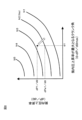
図8は、筒内圧上昇率(dP/dΘ)と筒内圧上昇率が最大となるクランク角(Θ‐dP/dΘmax)との関係に対して、発生する異音の大きさを測定した例を示している。図8に示される5本の曲線は、各々、異音の大きさのレベルであるN1[dB]、N2[dB]、N3[dB]、N4[dB]及びN5[dB]を示している。なお、異音の大きさは、N1からN5にかけて順次大きくなる。すなわち、図8のグラフに示すように、筒内圧上昇率が最大となるクランク角(Θ‐dP/dΘmax)が大きい程、発生する異音のレベルは小さくなり、筒内圧上昇率が最大となるクランク角(Θ‐dP/dΘmax)が小さい程、異音のレベルは大きくなる。ここで、図8のグラフにおいては、N2が、許容可能な異音の大きさの閾値、すなわち、許容閾値(Na)として設定されているものとすると、筒内圧許容上昇率算出部54は、許容閾値(Na=N2)に対応する筒内圧上昇率(dP/dΘ)を許容上昇率(dPa/dΘ)として算出する。具体的には、図8に例示されるように、筒内圧上昇率が最大となるクランク角(Θ‐dP/dΘmax)がΘ1である場合、許容上昇率(dPa/dΘ)は、異音の大きさN2に対応する数値であるPa/dΘ=dPa1/dΘとして算出される。すなわち、筒内圧許容上昇率算出部54は、許容閾値(Na)に基づいて、各気筒の筒内圧上昇率が最大となるクランク角(Θ‐dP/dΘmax)における筒内圧上昇率の許容値である許容上昇率(dPa/dΘ)を算出する。 Figure 8 shows an example of measuring the magnitude of abnormal noise generated with respect to the relationship between the rate of increase in cylinder pressure (dP/dΘ) and the crank angle at which the rate of increase in cylinder pressure is maximum (Θ-dP/dΘmax). Showing. The five curves shown in FIG. 8 each indicate the level of abnormal noise, N1 [dB], N2 [dB], N3 [dB], N4 [dB], and N5 [dB]. . Note that the magnitude of the abnormal noise increases sequentially from N1 to N5. In other words, as shown in the graph of Fig. 8, the larger the crank angle (Θ-dP/dΘmax) at which the rate of increase in cylinder pressure is maximum, the lower the level of abnormal noise generated, and the maximum rate of increase in cylinder pressure. The smaller the crank angle (Θ-dP/dΘmax), the higher the level of abnormal noise. Here, in the graph of FIG. 8, assuming that N2 is set as the threshold value of the allowable abnormal noise level, that is, the allowable threshold value (Na), the cylinder pressure allowable increase rate calculation unit 54 calculates the following: The in-cylinder pressure increase rate (dP/dΘ) corresponding to the allowable threshold value (Na=N2) is calculated as the allowable increase rate (dPa/dΘ). Specifically, as illustrated in FIG. 8, when the crank angle (Θ-dP/dΘmax) at which the in-cylinder pressure rise rate is maximum is Θ1, the allowable rise rate (dPa/dΘ) is It is calculated as Pa/dΘ=dPa1/dΘ, which is a numerical value corresponding to the size N2. That is, the cylinder pressure permissible increase rate calculation unit 54 calculates the permissible value of the cylinder pressure increase rate at the crank angle (Θ-dP/dΘmax) at which the cylinder pressure increase rate of each cylinder is maximum, based on the permissible threshold value (Na). A certain allowable rate of increase (dPa/dΘ) is calculated.
図3に戻り、点火時期制御部55の異音判定部56は、筒内圧最大上昇率算出部53が算出した筒内圧の最大上昇率(dP/dΘmax)と、筒内圧許容上昇率算出部54が算出した許容上昇率(dPa/dΘ)とを比較し、最大上昇率(dP/dΘmax)が許容上昇率(dPa/dΘ)よりも大きいか否かを判定する。すなわち、最大上昇率(dP/dΘmax)が許容上昇率(dPa/dΘ)よりも大きい場合は、異音の大きさが、許容閾値(Na)を超えていると判定される。 Returning to FIG. 3, the abnormal noise determination unit 56 of the ignition timing control unit 55 uses the maximum rate of increase in cylinder pressure (dP/dΘmax) calculated by the maximum rate of increase in cylinder pressure calculation unit 53 and the allowable rate of increase in cylinder pressure calculation unit 54. It is determined whether the maximum rate of increase (dP/dΘmax) is larger than the permissible rate of increase (dPa/dΘ). That is, when the maximum rate of increase (dP/dΘmax) is larger than the allowable rate of increase (dPa/dΘ), it is determined that the magnitude of the abnormal noise exceeds the allowable threshold (Na).
点火時期制御部55の基本点火時期算出部57は、運転状態取得部51からエンジン100の運転状態を取得し、現在の運転状態において最大トルクが発生する点火プラグ20の点火時期(基本点火時期)を算出する。
The basic ignition timing calculation unit 57 of the ignition timing control unit 55 acquires the operating state of the
点火時期制御部55の点火時期補正部58は、基本点火時期算出部57にて算出した基本点火時期に対し、異音判定部56にて判定した結果に基づく補正を加え、最終的な点火プラグ20の点火時期を算出する。 The ignition timing correction section 58 of the ignition timing control section 55 corrects the basic ignition timing calculated by the basic ignition timing calculation section 57 based on the result determined by the abnormal noise determination section 56, and adjusts the final spark plug. Calculate the ignition timing of 20.
次に、制御装置50による点火時期の制御方法の手順について、図4を参照しながら説明する。なお、図4に示す点火時期の制御は、エンジン100の各気筒の燃焼サイクル毎に実行される。
図4に示すように、ステップS1において、制御装置50の運転状態取得部51は、各種センサの検出信号等からエンジン100の現在の運転状態を取得する。
Next, the procedure of the ignition timing control method by the
As shown in FIG. 4, in step S1, the operating state acquisition unit 51 of the
次に、ステップS2において、制御装置50のクランク角算出部52は、運転状態取得部51が取得したエンジン100の運転状態に基づいて、エンジン100の各気筒の筒内圧上昇率(dP/dΘ)が最大となるクランク角(Θ‐dP/dΘmax)を算出する。さらに、ステップS3において、制御装置50の筒内圧最大上昇率算出部53は、エンジン100の運転状態に基づいて、各気筒の筒内圧上昇率の最大値である最大上昇率(dP/dΘmax)を算出する。
Next, in step S2, the crank angle calculating unit 52 of the
次に、図4のステップS4において、制御装置50の筒内圧許容上昇率算出部54は、エンジン100の運転状態に応じた許容閾値(Na)基づいて、筒内圧上昇率(dP/dΘ)が最大となるクランク角(Θ‐dP/dΘmax)における許容上昇率(dPa/dΘ)を算出する。
Next, in step S4 of FIG. 4, the in-cylinder pressure allowable increase rate calculation unit 54 of the
次に、図4のステップS5において、点火時期制御部55の異音判定部56は、筒内圧の最大上昇率(dP/dΘmax)と許容上昇率(dPa/dΘ)とを比較し、最大上昇率(dP/dΘmax)が許容上昇率(dPa/dΘ)よりも大きいか否かを判定する。すなわち、最大上昇率(dP/dΘmax)が許容上昇率(dPa/dΘ)よりも大きい場合は、異音の大きさが、許容閾値(Na)を超えていると判定される。換言すれば、図8に示されるNa=N2の曲線よりも左上の領域は、許容可能な異音の大きさの閾値(Na=N2)を超えていると判定される領域である。具体的には、図8に例示されるように、筒内圧上昇率が最大となるクランク角(Θ‐dP/dΘmax)がΘ1である場合の最大上昇率(dP1/dΘmax)は、許容上昇率(dPa1/dΘ)よりも大きい。そのため、異音判定部56は、異音の大きさが、許容閾値(Na=N2)を超えていると判定する。 Next, in step S5 of FIG. 4, the abnormal noise determination unit 56 of the ignition timing control unit 55 compares the maximum rate of increase in cylinder pressure (dP/dΘmax) with the allowable rate of increase (dPa/dΘ), and determines the maximum increase in cylinder pressure. It is determined whether the rate (dP/dΘmax) is larger than the allowable increase rate (dPa/dΘ). That is, when the maximum rate of increase (dP/dΘmax) is larger than the allowable rate of increase (dPa/dΘ), it is determined that the magnitude of the abnormal noise exceeds the allowable threshold (Na). In other words, the area above and to the left of the Na=N2 curve shown in FIG. 8 is the area where it is determined that the threshold value (Na=N2) of the allowable abnormal noise level is exceeded. Specifically, as illustrated in FIG. 8, when the crank angle (Θ-dP/dΘmax) at which the in-cylinder pressure rise rate is maximum is Θ1, the maximum increase rate (dP1/dΘmax) is the allowable increase rate. (dPa1/dΘ). Therefore, the abnormal noise determination unit 56 determines that the magnitude of the abnormal noise exceeds the allowable threshold (Na=N2).
ステップS5において、最大上昇率(dP/dΘmax)が許容上昇率(dPa/dΘ)よりも大きいと判定された場合は、ステップS6に進む。ステップS6において、点火時期制御部55の点火時期補正部58は、基本点火時期算出部57が算出した基本点火時期に対して、点火時期を予め設定された所定角だけ遅角補正する。このように、制御装置50は、点火時期を遅角させることにより、図8の矢印に示すように、最大上昇率(dP/dΘmax)を許容上昇率(dPa/dΘ)よりも小さくなるように変化させることができる。すなわち、制御装置50は、点火時期を遅角させることにより、エンジン100に発生する異音の大きさを、許容閾値(Na)を下回るように抑制することができる。なお、ステップS6では、点火時期補正部58は、基本点火時期に対して点火時期を遅角補正しているが、これに限定されず、全気筒の平均点火時期又は前回の燃焼サイクルにおける点火時期に対して遅角補正を行ってもよい。
一方、ステップS5において、最大上昇率(dP/dΘmax)が許容上昇率(dPa/dΘ)以下の値であると判定された場合は、点火時期の補正は行われず、制御は終了する。
If it is determined in step S5 that the maximum rate of increase (dP/dΘmax) is greater than the allowable rate of increase (dPa/dΘ), the process advances to step S6. In step S6, the ignition timing correction section 58 of the ignition timing control section 55 retards the ignition timing by a predetermined angle with respect to the basic ignition timing calculated by the basic ignition timing calculation section 57. In this way, by retarding the ignition timing, the
On the other hand, if it is determined in step S5 that the maximum rate of increase (dP/dΘmax) is less than or equal to the allowable rate of increase (dPa/dΘ), the ignition timing is not corrected and the control ends.
なお、異音の大きさと、筒内圧上昇率(dP/dΘ)と、筒内圧上昇率が最大となるクランク角(Θ‐dP/dΘmax)との関係は、図8のグラフに例示されるものに限定されず、エンジン100の運転状態によって異なる。例えば、エンジン100の回転速度が図8の例よりも高い場合における、異音の大きさと、筒内圧上昇率(dP/dΘ)と、筒内圧上昇率が最大となるクランク角(Θ‐dP/dΘmax)との関係の例を図9に示す。図9に示される5本の曲線は、各々、異音の大きさのレベルであるN3[dB]、N4[dB]、N5[dB]、N6[dB]及びN7[dB]を示している。N6[dB]及びN7[dB]は、N5[dB]よりも異音の大きさのレベルが大きい。すなわち、エンジン100の回転速度が高くなる程、筒内圧上昇率(dP/dΘ)に対する異音の大きさは大きくなる傾向にある。
The relationship between the magnitude of the abnormal noise, the rate of increase in cylinder pressure (dP/dΘ), and the crank angle at which the rate of increase in cylinder pressure is maximum (Θ-dP/dΘmax) is illustrated in the graph of FIG. It is not limited to, but varies depending on the operating state of
また、エンジン100の回転速度が高くなる程、暗騒音(雑音)が大きくなるため、図9のグラフにおいては、N2よりも異音の大きさのレベルが高いN5が、許容閾値(Na)として設定されている。従って、エンジン100の回転速度が高い程、筒内圧許容上昇率算出部54が算出する許容上昇率(dPa/dΘ)は大きくなる。すなわち、筒内圧許容上昇率算出部54は、エンジン100の運転状態に応じた許容閾値(Na)に基づいて許容上昇率(dPa/dΘ)を算出することになる。
Also, as the rotational speed of the
具体的には、図9に例示されるように、筒内圧上昇率が最大となるクランク角(Θ‐dP/dΘmax)が、図8の例と同様のΘ1である場合、許容上昇率(dPa1/dΘ)は、異音の大きさN5に対応する数値であるPa/dΘ=dPa2/dΘとして算出される。図9の例の許容上昇率(dPa2/dΘ)は、図8の例の許容上昇率(dPa1/dΘ)よりも大きい。また、筒内圧上昇率が最大となるクランク角(Θ‐dP/dΘmax)がΘ1である場合の最大上昇率(dP2/dΘmax)が、許容上昇率(dPa2/dΘ)よりも大きいと判定された場合は、制御装置50は、点火時期を遅角補正する。これにより、制御装置50は、図9の矢印に示すように、最大上昇率(dP/dΘmax)が許容上昇率(dPa2/dΘ)以下の数値となるように調整する。
Specifically, as illustrated in FIG. 9, when the crank angle (Θ-dP/dΘmax) at which the in-cylinder pressure increase rate is maximum is Θ1, which is the same as the example in FIG. 8, the allowable increase rate (dPa1 /dΘ) is calculated as Pa/dΘ=dPa2/dΘ, which is a numerical value corresponding to the noise level N5. The allowable increase rate (dPa2/dΘ) in the example of FIG. 9 is larger than the allowable increase rate (dPa1/dΘ) in the example of FIG. Furthermore, when the crank angle (Θ-dP/dΘmax) at which the cylinder pressure rise rate is maximum is Θ1, the maximum rate of increase (dP2/dΘmax) was determined to be larger than the allowable rate of increase (dPa2/dΘ). If so, the
すなわち、図8,9に示すように、本例の制御装置50は、エンジン100の回転速度等の運転状態の条件に応じて、異音の大きさと、筒内圧上昇率(dP/dΘ)と、筒内圧上昇率が最大となるクランク角(Θ‐dP/dΘmax)との関係、及び、許容閾値(Na)を含む制御マップを複数パターン記憶している。
That is, as shown in FIGS. 8 and 9, the
なお、点火時期が遅角補正された場合は、エンジン100の出力トルクが低下するため、制御装置50は、たとえば吸気通路11のスロットルバルブ14の開度を制御し、エンジン100の吸気量を増加させることにより、出力トルクを補填してもよい。
Note that when the ignition timing is retarded, the output torque of the
以上より、本実施形態に係る制御装置50は、筒内圧の最大上昇率と許容上昇率とを比較して、最大上昇率が許容上昇率よりも大きい場合に、各気筒の点火時期を遅角させる。これにより、制御装置50は、筒内圧上昇率が許容上昇率を超えないように調整するため、エンジン100の筒内圧の急激な上昇に起因する異音の発生を抑制することができる。
As described above, the
また、エンジン100は、上死点におけるピストン102の位置を変更することにより圧縮比を変更可能な複リンク式の可変圧縮比エンジンであり、ピストン102は、複数のリンク部材を介して、クランクシャフト103に連結されている。このように、複数のリンク部材を有するエンジン100では、部材同士の接続箇所が増える分、より異音が発生しやすくなるが、上述のように、最大上昇率が許容上昇率よりも大きい場合に点火時期を遅角させることによって、異音の発生を抑制することができる。
Further, the
また、各気筒の筒内圧上昇率が最大となるクランク角が上死点から離れる程、許容上昇率は大きく設定される。これにより、制御装置50は、クランク角が大きくなるほど異音の大きさが小さくなるという傾向に対応して、異音の発生を抑制することができる。
Furthermore, the allowable rate of increase is set to be larger as the crank angle at which the rate of increase in cylinder pressure in each cylinder becomes maximum is farther away from top dead center. Thereby, the
また、エンジン100の回転速度が高い程、許容上昇率は大きく設定される。これにより、制御装置50は、エンジン100の回転速度の上昇に伴って暗騒音(雑音)が増加するという事情にも対応して、異音の発生を抑制することができる。
Further, the higher the rotational speed of
なお、本実施形態において、エンジン100は可変圧縮比エンジンであるが、これに限定されず、制御装置50の制御方法を用いて、可変圧縮比エンジン以外のエンジンに関しても異音の発生を抑制することができる。
Note that in this embodiment, the
50…制御装置
51…運転状態取得部
52…クランク角算出部
53…筒内圧最大上昇率算出部
54…筒内圧許容上昇率算出部
55…点火時期制御部
100…エンジン
102…ピストン
103…クランクシャフト
104…アッパリンク(リンク部材)
105…ロアリンク(リンク部材)
50...Control device 51...Operating state acquisition section 52...Crank angle calculation section 53...In-cylinder pressure maximum increase rate calculation section 54...In-cylinder pressure allowable increase rate calculation section 55...Ignition
105...Lower link (link member)
Claims (4)
前記エンジンの運転状態に基づいて、各気筒の筒内圧上昇率が最大となるクランク角、及び、前記各気筒の筒内圧上昇率の最大値である最大上昇率を算出し、
前記エンジンの運転状態に応じた異音の大きさの許容閾値に基づいて、前記各気筒の筒内圧上昇率が最大となるクランク角における前記筒内圧上昇率の許容値である許容上昇率を算出し、かつ、前記各気筒の筒内圧上昇率が最大となるクランク角が上死点から離れる程、前記許容上昇率を大きく設定し、
前記最大上昇率と前記許容上昇率とを比較して、前記最大上昇率が前記許容上昇率よりも大きい場合に、前記各気筒の点火時期を遅角させる、エンジンの制御方法。 Obtain the operating status of the vehicle's engine,
Based on the operating state of the engine, calculate the crank angle at which the in-cylinder pressure increase rate of each cylinder is maximum, and the maximum increase rate that is the maximum value of the in-cylinder pressure increase rate of each cylinder,
Calculate an allowable increase rate that is an allowable value for the in-cylinder pressure increase rate at a crank angle at which the in-cylinder pressure increase rate of each cylinder is maximum, based on an allowable threshold value for the magnitude of abnormal noise depending on the operating state of the engine. and the allowable increase rate is set to be larger as the crank angle at which the in-cylinder pressure increase rate of each cylinder is maximum is farther from top dead center,
An engine control method comprising: comparing the maximum rate of increase with the permissible rate of increase, and retarding the ignition timing of each cylinder if the maximum rate of increase is larger than the permissible rate of increase.
前記ピストンは、複数のリンク部材を介して、前記エンジンのクランクシャフトに連結されている、請求項1に記載のエンジンの制御方法。 The engine is a multi-link variable compression ratio engine that can change the compression ratio by changing the position of the piston at top dead center,
The method for controlling an engine according to claim 1, wherein the piston is connected to a crankshaft of the engine via a plurality of link members.
前記エンジンの記運転状態に基づいて、各気筒の筒内圧上昇率が最大となるクランク角を算出するクランク角算出部と、
前記エンジンの運転状態に基づいて、前記各気筒の筒内圧上昇率の最大値である最大上昇率を算出する筒内圧最大上昇率算出部と、
前記エンジンの運転状態に応じた異音の大きさの許容閾値に基づいて、前記各気筒の筒内圧上昇率が最大となるクランク角における前記筒内圧上昇率の許容値である許容上昇率を算出し、かつ、前記各気筒の筒内圧上昇率が最大となるクランク角が上死点から離れる程、前記許容上昇率を大きく設定する筒内圧許容上昇率算出部と、
前記最大上昇率と前記許容上昇率とを比較して、前記最大上昇率が前記許容上昇率よりも大きい場合に、前記各気筒の点火時期を遅角させる点火時期制御部とを備える、エンジンの制御装置。 an operating state acquisition unit that obtains the operating state of the engine of the vehicle;
a crank angle calculation unit that calculates a crank angle at which the in-cylinder pressure increase rate of each cylinder is maximum based on the operating state of the engine;
an in-cylinder pressure maximum increase rate calculation unit that calculates a maximum increase rate that is a maximum value of the in-cylinder pressure increase rate of each cylinder based on the operating state of the engine;
Calculate an allowable increase rate that is an allowable value for the in-cylinder pressure increase rate at a crank angle at which the in-cylinder pressure increase rate of each cylinder is maximum, based on an allowable threshold value for the magnitude of abnormal noise depending on the operating state of the engine. and an in-cylinder pressure allowable increase rate calculation unit that sets the allowable increase rate to be larger as the crank angle at which the in-cylinder pressure increase rate of each cylinder is maximum is farther from top dead center ;
an ignition timing control section that compares the maximum rate of increase with the allowable rate of increase and retards the ignition timing of each cylinder if the maximum rate of increase is greater than the rate of increase; Control device.
Priority Applications (1)
| Application Number | Priority Date | Filing Date | Title |
|---|---|---|---|
| JP2020099942A JP7439655B2 (en) | 2020-06-09 | 2020-06-09 | Engine control method and control device |
Applications Claiming Priority (1)
| Application Number | Priority Date | Filing Date | Title |
|---|---|---|---|
| JP2020099942A JP7439655B2 (en) | 2020-06-09 | 2020-06-09 | Engine control method and control device |
Publications (2)
| Publication Number | Publication Date |
|---|---|
| JP2021195868A JP2021195868A (en) | 2021-12-27 |
| JP7439655B2 true JP7439655B2 (en) | 2024-02-28 |
Family
ID=79197581
Family Applications (1)
| Application Number | Title | Priority Date | Filing Date |
|---|---|---|---|
| JP2020099942A Active JP7439655B2 (en) | 2020-06-09 | 2020-06-09 | Engine control method and control device |
Country Status (1)
| Country | Link |
|---|---|
| JP (1) | JP7439655B2 (en) |
Citations (4)
| Publication number | Priority date | Publication date | Assignee | Title |
|---|---|---|---|---|
| JP2006177270A (en) | 2004-12-24 | 2006-07-06 | Nissan Motor Co Ltd | Variable compression ratio mechanism of internal combustion engine |
| JP2013057268A (en) | 2011-09-07 | 2013-03-28 | Mazda Motor Corp | Direct injection gasoline engine |
| JP2015068193A (en) | 2013-09-27 | 2015-04-13 | 三菱自動車工業株式会社 | Control device for engine |
| US20160138486A1 (en) | 2014-11-17 | 2016-05-19 | Hyundai Motor Company | Method and apparatus for fuel injection of engine system |
Family Cites Families (2)
| Publication number | Priority date | Publication date | Assignee | Title |
|---|---|---|---|---|
| JPH02145640U (en) * | 1989-05-16 | 1990-12-11 | ||
| JPH10110638A (en) * | 1996-10-04 | 1998-04-28 | Fuji Heavy Ind Ltd | Combustion controller for engine |
-
2020
- 2020-06-09 JP JP2020099942A patent/JP7439655B2/en active Active
Patent Citations (4)
| Publication number | Priority date | Publication date | Assignee | Title |
|---|---|---|---|---|
| JP2006177270A (en) | 2004-12-24 | 2006-07-06 | Nissan Motor Co Ltd | Variable compression ratio mechanism of internal combustion engine |
| JP2013057268A (en) | 2011-09-07 | 2013-03-28 | Mazda Motor Corp | Direct injection gasoline engine |
| JP2015068193A (en) | 2013-09-27 | 2015-04-13 | 三菱自動車工業株式会社 | Control device for engine |
| US20160138486A1 (en) | 2014-11-17 | 2016-05-19 | Hyundai Motor Company | Method and apparatus for fuel injection of engine system |
Also Published As
| Publication number | Publication date |
|---|---|
| JP2021195868A (en) | 2021-12-27 |
Similar Documents
| Publication | Publication Date | Title |
|---|---|---|
| US6779508B2 (en) | Control system of internal combustion engine | |
| US10683797B2 (en) | Waste gate valve control method and control device | |
| US9863338B2 (en) | Engine control apparatus | |
| CN1550653A (en) | Knock control device and method for variable cylinder internal combustion engine | |
| JP4339572B2 (en) | Control device for internal combustion engine | |
| JP4438368B2 (en) | Control device for variable compression ratio engine | |
| CN110730861B (en) | Method and device for controlling internal combustion engine | |
| CN111065805B (en) | Method and device for controlling internal combustion engine | |
| WO2017009962A1 (en) | Internal combustion engine control device | |
| JP7439655B2 (en) | Engine control method and control device | |
| JP4277623B2 (en) | Ignition timing control device for internal combustion engine with variable compression ratio mechanism | |
| JP6191230B2 (en) | Control device and control method for internal combustion engine | |
| JP4003182B2 (en) | Variable valve control device for internal combustion engine | |
| JP4232636B2 (en) | Control device for internal combustion engine | |
| JPH10141097A (en) | Control device for internal combustion engine, valve timing control device, and valve timing control method | |
| US10563595B2 (en) | Control device of internal combustion engine | |
| CN115803519B (en) | Engine control method and control device | |
| JP4075056B2 (en) | Variable valve control device for internal combustion engine | |
| JP4134821B2 (en) | Control device for internal combustion engine | |
| JP2007009835A (en) | Control device for internal combustion engine | |
| CN121593882A (en) | Abnormality diagnosis device for gas sensor | |
| JP4033028B2 (en) | Variable valve control device for internal combustion engine | |
| JP2004036582A (en) | Control process for internal combustion engine |
Legal Events
| Date | Code | Title | Description |
|---|---|---|---|
| A621 | Written request for application examination |
Free format text: JAPANESE INTERMEDIATE CODE: A621 Effective date: 20230404 |
|
| A131 | Notification of reasons for refusal |
Free format text: JAPANESE INTERMEDIATE CODE: A131 Effective date: 20231024 |
|
| A977 | Report on retrieval |
Free format text: JAPANESE INTERMEDIATE CODE: A971007 Effective date: 20231025 |
|
| A521 | Request for written amendment filed |
Free format text: JAPANESE INTERMEDIATE CODE: A523 Effective date: 20231220 |
|
| TRDD | Decision of grant or rejection written | ||
| A01 | Written decision to grant a patent or to grant a registration (utility model) |
Free format text: JAPANESE INTERMEDIATE CODE: A01 Effective date: 20240116 |
|
| A61 | First payment of annual fees (during grant procedure) |
Free format text: JAPANESE INTERMEDIATE CODE: A61 Effective date: 20240129 |
|
| R151 | Written notification of patent or utility model registration |
Ref document number: 7439655 Country of ref document: JP Free format text: JAPANESE INTERMEDIATE CODE: R151 |