EP1433935A2 - Brennkraftmaschine mit direkter Kraftstoffeinspritzung - Google Patents
Brennkraftmaschine mit direkter Kraftstoffeinspritzung Download PDFInfo
- Publication number
- EP1433935A2 EP1433935A2 EP03029237A EP03029237A EP1433935A2 EP 1433935 A2 EP1433935 A2 EP 1433935A2 EP 03029237 A EP03029237 A EP 03029237A EP 03029237 A EP03029237 A EP 03029237A EP 1433935 A2 EP1433935 A2 EP 1433935A2
- Authority
- EP
- European Patent Office
- Prior art keywords
- fuel injection
- fuel
- injection engine
- direct
- air
- Prior art date
- Legal status (The legal status is an assumption and is not a legal conclusion. Google has not performed a legal analysis and makes no representation as to the accuracy of the status listed.)
- Withdrawn
Links
- 239000000446 fuel Substances 0.000 title claims abstract description 695
- 238000002347 injection Methods 0.000 title claims abstract description 349
- 239000007924 injection Substances 0.000 title claims abstract description 349
- 238000002485 combustion reaction Methods 0.000 claims abstract description 299
- 239000000203 mixture Substances 0.000 claims abstract description 128
- 230000035515 penetration Effects 0.000 claims description 24
- 239000012530 fluid Substances 0.000 claims description 20
- 230000002093 peripheral effect Effects 0.000 claims description 20
- 238000000034 method Methods 0.000 claims description 12
- 230000008859 change Effects 0.000 claims description 3
- 230000002829 reductive effect Effects 0.000 abstract description 11
- 238000009826 distribution Methods 0.000 description 27
- 230000007423 decrease Effects 0.000 description 9
- 230000006870 function Effects 0.000 description 9
- 238000009792 diffusion process Methods 0.000 description 6
- 230000036961 partial effect Effects 0.000 description 6
- 230000000694 effects Effects 0.000 description 5
- 230000007246 mechanism Effects 0.000 description 5
- 238000002156 mixing Methods 0.000 description 5
- 230000003247 decreasing effect Effects 0.000 description 4
- 230000006835 compression Effects 0.000 description 3
- 238000007906 compression Methods 0.000 description 3
- 238000010276 construction Methods 0.000 description 3
- 239000000498 cooling water Substances 0.000 description 2
- 230000000670 limiting effect Effects 0.000 description 2
- 238000000889 atomisation Methods 0.000 description 1
- 230000015572 biosynthetic process Effects 0.000 description 1
- 238000001816 cooling Methods 0.000 description 1
- 230000003111 delayed effect Effects 0.000 description 1
- 230000002939 deleterious effect Effects 0.000 description 1
- 229930195733 hydrocarbon Natural products 0.000 description 1
- 150000002430 hydrocarbons Chemical class 0.000 description 1
- 238000012986 modification Methods 0.000 description 1
- 230000004048 modification Effects 0.000 description 1
- 230000000979 retarding effect Effects 0.000 description 1
- 230000007480 spreading Effects 0.000 description 1
- 238000003892 spreading Methods 0.000 description 1
- 238000003860 storage Methods 0.000 description 1
- 238000005728 strengthening Methods 0.000 description 1
Images







Classifications
-
- F—MECHANICAL ENGINEERING; LIGHTING; HEATING; WEAPONS; BLASTING
- F02—COMBUSTION ENGINES; HOT-GAS OR COMBUSTION-PRODUCT ENGINE PLANTS
- F02D—CONTROLLING COMBUSTION ENGINES
- F02D13/00—Controlling the engine output power by varying inlet or exhaust valve operating characteristics, e.g. timing
- F02D13/02—Controlling the engine output power by varying inlet or exhaust valve operating characteristics, e.g. timing during engine operation
- F02D13/0203—Variable control of intake and exhaust valves
- F02D13/0215—Variable control of intake and exhaust valves changing the valve timing only
-
- F—MECHANICAL ENGINEERING; LIGHTING; HEATING; WEAPONS; BLASTING
- F02—COMBUSTION ENGINES; HOT-GAS OR COMBUSTION-PRODUCT ENGINE PLANTS
- F02B—INTERNAL-COMBUSTION PISTON ENGINES; COMBUSTION ENGINES IN GENERAL
- F02B17/00—Engines characterised by means for effecting stratification of charge in cylinders
- F02B17/005—Engines characterised by means for effecting stratification of charge in cylinders having direct injection in the combustion chamber
-
- F—MECHANICAL ENGINEERING; LIGHTING; HEATING; WEAPONS; BLASTING
- F02—COMBUSTION ENGINES; HOT-GAS OR COMBUSTION-PRODUCT ENGINE PLANTS
- F02B—INTERNAL-COMBUSTION PISTON ENGINES; COMBUSTION ENGINES IN GENERAL
- F02B23/00—Other engines characterised by special shape or construction of combustion chambers to improve operation
- F02B23/08—Other engines characterised by special shape or construction of combustion chambers to improve operation with positive ignition
- F02B23/10—Other engines characterised by special shape or construction of combustion chambers to improve operation with positive ignition with separate admission of air and fuel into cylinder
- F02B23/101—Other engines characterised by special shape or construction of combustion chambers to improve operation with positive ignition with separate admission of air and fuel into cylinder the injector being placed on or close to the cylinder centre axis, e.g. with mixture formation using spray guided concepts
-
- F—MECHANICAL ENGINEERING; LIGHTING; HEATING; WEAPONS; BLASTING
- F02—COMBUSTION ENGINES; HOT-GAS OR COMBUSTION-PRODUCT ENGINE PLANTS
- F02D—CONTROLLING COMBUSTION ENGINES
- F02D41/00—Electrical control of supply of combustible mixture or its constituents
- F02D41/30—Controlling fuel injection
- F02D41/3011—Controlling fuel injection according to or using specific or several modes of combustion
- F02D41/3017—Controlling fuel injection according to or using specific or several modes of combustion characterised by the mode(s) being used
- F02D41/3023—Controlling fuel injection according to or using specific or several modes of combustion characterised by the mode(s) being used a mode being the stratified charge spark-ignited mode
- F02D41/3029—Controlling fuel injection according to or using specific or several modes of combustion characterised by the mode(s) being used a mode being the stratified charge spark-ignited mode further comprising a homogeneous charge spark-ignited mode
-
- Y—GENERAL TAGGING OF NEW TECHNOLOGICAL DEVELOPMENTS; GENERAL TAGGING OF CROSS-SECTIONAL TECHNOLOGIES SPANNING OVER SEVERAL SECTIONS OF THE IPC; TECHNICAL SUBJECTS COVERED BY FORMER USPC CROSS-REFERENCE ART COLLECTIONS [XRACs] AND DIGESTS
- Y02—TECHNOLOGIES OR APPLICATIONS FOR MITIGATION OR ADAPTATION AGAINST CLIMATE CHANGE
- Y02T—CLIMATE CHANGE MITIGATION TECHNOLOGIES RELATED TO TRANSPORTATION
- Y02T10/00—Road transport of goods or passengers
- Y02T10/10—Internal combustion engine [ICE] based vehicles
- Y02T10/12—Improving ICE efficiencies
Definitions
- the present invention generally relates to a spark ignition internal combustion engine with direct fuel injection. More specifically, the present invention relates to a spark ignition internal combustion engine with direct fuel injection that achieves an improved combustibility of the fuel during stratified combustion.
- a spark ignition internal combustion engine with direct fuel injection is configured and arranged to perform a highly lean combustion by directly injecting a fuel into a cylinder from a fuel injection valve and forming a stratified air-fuel mixture in the cylinder during spark ignition combustion.
- the fuel consumption can be significantly reduced, particularly when the engine is operating under low and medium loads.
- An appropriate stratified air-fuel mixture can be formed in the cylinder by providing a bowl-shaped cavity on a piston, setting a fuel stream injected from the fuel injection valve to collide against a wall surface of the bowl-shaped cavity, and forming a fuel stream circulation along the wall surface of the bowl-shaped cavity.
- Japanese Laid-Open Patent Publication No. 11-82028 discloses a direct fuel injection spark ignition internal combustion engine that forms an appropriate stratified air-fuel mixture in a cylinder by disposing the fuel injection valve in the vicinity directly above the cavity, setting the fuel stream to collide against the cavity perimeter wall surface, and thereby forming a fuel stream circulation toward the center part of the cavity.
- the present invention considers the abovementioned problems, and has the object to enable forming of an air-fuel mixture mass of an appropriate air-fuel ratio and size according to the operating conditions of the engine in a combustion chamber having a fixed-volume cavity.
- a direct fuel injection engine that basically comprises a combustion chamber, a spark plug, a fuel injection valve, a piston and a controller.
- the spark plug is positioned in an upper surface of the combustion chamber.
- the fuel injection valve is positioned in a substantially center portion of the upper surface of the combustion chamber, the fuel injection valve being configured and arranged to directly inject a fuel stream inside the combustion chamber.
- the piston has a guide wall surface being configured and arranged to guide the fuel stream injected from the fuel injection valve.
- the controller is configured and arranged to control operations of the spark plug and the fuel injection valve.
- the controller is further configured and arranged to ignite a first air-fuel mixture formed directly after the fuel stream is injected from the fuel injection valve and prior to a majority of the fuel stream being guide by the guide wall surface of the piston when the direct fuel injection engine is operating in a low-load stratified combustion region.
- the controller is further configured and arranged to ignite a second air-fuel mixture formed after a majority of the fuel stream is guided to an upper portion of the combustion chamber by the guide wall surface of the piston when the direct fuel injection engine is operating in a high-load stratified combustion region.
- Figure 1 is a partial cross-sectional view of an injection portion of a direct fuel injection spark ignition internal combustion engine in accordance with a first embodiment of the present invention
- Figure 2 is a partial cross-sectional view of one example of a fuel injection valve with a controllable fuel injection angle in accordance with the first embodiment of the present invention
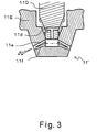
- Figure 3 is a partial cross-sectional view of another example of a fuel injection valve with a controllable fuel injection angle in accordance with the first embodiment of the present invention
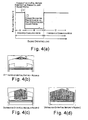
- Figure 4(a) is a diagrammatic chart illustrating the relationship between the engine operating load and the fuel stream angle in accordance with the first embodiment of the present invention
- Figure 4(b) is a diagrammatic cross-sectional view of a combustion chamber illustrating distribution of the air-fuel mixture in the combustion chamber under a low-load stratified combustion region shown as "A" in Figure 4(a);
- Figure 4(c) is a diagrammatic cross-sectional view of a combustion chamber illustrating distribution of the air-fuel mixture in the combustion chamber under a high-load stratified combustion region shown as "B" in Figure 4(a);
- Figure 4(d) is a diagrammatic cross-sectional view of a combustion chamber illustrating distributions of the air-fuel mixture in the combustion chamber under a homogeneous combustion region shown as "C" in Figure 4(a);
- Figure 5(a) is a flow chart of the control executed in a controller of the direct fuel injection engine in accordance with the first embodiment of the present invention
- Figure 5(b) is a flow chart of an alternate control executed in the controller of the direct fuel injection engine in accordance with the first embodiment of the present invention
- Figure 6 is a partial cross-sectional view of an injection portion of a direct fuel injection spark ignition internal combustion engine in accordance with a second embodiment of the present invention.
- Figure 7(a) is a diagrammatic chart illustrating the relationship between the engine operating load and the injected fuel mass ratio to the air in accordance with the second embodiment of the present invention
- Figure 7(b) is a diagrammatic cross-sectional view of a combustion chamber illustrating distribution of the air-fuel mixture in the combustion chamber under a low-load stratified combustion region shown as "A" in Figure 7(a);
- Figure 7(c) is a diagrammatic cross-sectional view of a combustion chamber illustrating distribution of the air-fuel mixture in the combustion chamber under a high-load stratified combustion region shown as "B" in Figure 7(a);
- Figure 7(d) is a diagrammatic cross-sectional view of a combustion chamber illustrating distributions of the air-fuel mixture in the combustion chamber under a homogeneous combustion region shown as "C" in Figure 7(a);
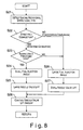
- Figure 8 is a flow chart of the control executed in a controller of the direct fuel injection engine in accordance with the second embodiment of the present invention.
- Figure 9(a) is a diagrammatic chart illustrating one example of the relationship between the engine operating load and the intake valve close timing in accordance with a third embodiment of the present invention.
- Figure 9(b) is a diagrammatic cross-sectional view of a combustion chamber illustrating distribution of the air-fuel mixture in the combustion chamber under a low-load stratified combustion region shown as "A" in Figure 9(a);
- Figure 9(c) is a diagrammatic cross-sectional view of a combustion chamber illustrating distribution of the air-fuel mixture in the combustion chamber under a high-load stratified combustion region shown as "B1" in Figure 9(a);
- Figure 9(d) is a diagrammatic cross-sectional view of a combustion chamber illustrating distribution of the air-fuel mixture in the combustion chamber under a high-load stratified combustion region shown as "B2" in Figure 9(a);
- Figure 9(e) is a diagrammatic cross-sectional view of a combustion chamber illustrating distributions of the air-fuel mixture in the combustion chamber under a homogeneous combustion region shown as "C" in Figure 9(a);
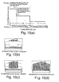
- Figure 10(a) is a diagrammatic chart illustrating another example of the relationship between the engine operating load and the intake valve close timing in accordance with the third embodiment of the present invention.
- Figure 10(b) is a diagrammatic cross-sectional view of a combustion chamber illustrating distribution of the air-fuel mixture in the combustion chamber under a low-load stratified combustion region shown as "A" in Figure 10(a);
- Figure 10(c) is a diagrammatic cross-sectional view of a combustion chamber illustrating distribution of the air-fuel mixture in the combustion chamber under a high-load stratified combustion region shown as "B" in Figure 10(a);
- Figure 10(d) is a diagrammatic cross-sectional view of a combustion chamber illustrating distributions of the air-fuel mixture in the combustion chamber under a homogeneous combustion region shown as "C" in Figure 10(a);
- Figure 11 is a flow chart of the control executed in a controller of the direct fuel injection engine in accordance with the third embodiment of the present invention.
- Figure 12(a) is a diagrammatic chart illustrating one example of the relationship between the engine operating load and the fuel pressure in accordance with a fourth embodiment of the present invention.
- Figure 12(b) is a diagrammatic cross-sectional view of a combustion chamber illustrating distribution of the air-fuel mixture in the combustion chamber under a low-load stratified combustion region shown as "A" in Figure 12(a);
- Figure 12(c) is a diagrammatic cross-sectional view of a combustion chamber illustrating distribution of the air-fuel mixture in the combustion chamber under a high-load stratified combustion region shown as "B" in Figure 12(a);
- Figure 12(d) is a diagrammatic cross-sectional view of a combustion chamber illustrating distributions of the air-fuel mixture in the combustion chamber under a homogeneous combustion region shown as "C" in Figure 12(a);
- Figure 13 is a flow chart of the control executed in a controller of the direct fuel injection engine in accordance with the fourth embodiment of the present invention.
- Figure 14(a) is a diagrammatic chart illustrating another example of the relationship between the engine operating load and the fuel injection pressure in accordance with the fifth embodiment of the present invention.
- Figure 14(b) is a diagrammatic cross-sectional view of a combustion chamber illustrating distribution of the air-fuel mixture in the combustion chamber under a low-load stratified combustion region shown as "A" in Figure 14(a);
- Figure 14(c) is a diagrammatic cross-sectional view of a combustion chamber illustrating distribution of the air-fuel mixture in the combustion chamber under a high-load stratified combustion region shown as "B1' " in Figure 14(a);
- Figure 14(d) is a diagrammatic cross-sectional view of a combustion chamber illustrating distributions of the air-fuel mixture in the combustion chamber under a homogeneous combustion region shown as "B2' " in Figure 14(a);
- Figure 14(e) is a diagrammatic cross-sectional view of a combustion chamber illustrating distributions of the air-fuel mixture in the combustion chamber under a homogeneous combustion region shown as "C" in Figure 14(a);
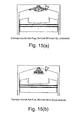
- Figure 15(a) is a diagrammatic view of the combustion chamber illustrating an air-fuel mixture distribution with a counterbore in the vicinity of the fuel injection valve;
- Figure 15(a) and 15(b) is a diagrammatic view of the combustion chamber illustrating an air-fuel mixture distribution without a counterbore in the vicinity of the fuel injection valve.
- FIG. 1 is a partial cross-sectional view of an injection portion of the direct fuel injection engine of the first embodiment.
- the injection portion of the direct fuel injection engine includes a cylinder head 1, a cylinder block 2, a piston 3, at least one intake valve 5, at least one exhaust valve 6, at least one intake port 7, at least one exhaust port 8, a fuel injection valve 11 and a spark plug 12.
- a combustion chamber 4 is basically defined by the cylinder head 1, the cylinder block 2 and the piston 3.
- a fuel pump 9 is disposed at the end of the camshaft which drives the intake valve 5.
- the fuel pump 9 can be arranged to be driven by a separately arranged electric motor.
- a variably valve timing mechanism 5a is preferably used to control a valve timing of the intake cam. Variably valve timing mechanism are well known in the art, and thus, the variably valve timing mechanism 5a will not be discussed or illustrated in detail herein.
- the fuel injection valve 11 is positioned in a substantially center portion of an upper surface of the combustion chamber 4.
- the fuel injection valve 11 is preferably centered or substantially centered on the center longitudinal axis of the piston 3.
- the fuel injection valve 11 is configured and arranged to inject the fuel pressurized by the fuel pump 9 and conveyed via a fuel conduit 10 into the combustion chamber 4.
- the fuel injection valve 11 is preferably configured and arranged such that the fuel stream injected from the fuel injection valve 11 spreads in a substantially conical shape in the combustion chamber 4.
- the fuel injection valve 11 is configured and arranged to inject a fuel stream in at least two different fuel injection angles, i.e., angles of an apex of the conical-shaped fuel stream, by changing a lift of a needle valve of the fuel injection valve 11.
- the fuel injection valve 11 utilizing a needle valve is disclosed in Japanese Laid Open Patent Publication No. H8-177684.
- the fuel injection valve 11 includes a needle valve 11A and a valve body 11B in which the needle valve 11A is inserted.
- the valve body 11B also includes a nozzle hole 11C.
- a fuel passageway 11a is formed in the valve body 11B.
- the downstream end of the fuel passageway 11a is branched into a lower side wide angle spout 11b and a narrow angle spout 11c.
- the wide angle spout 11b is arranged to be perpendicular to the axial direction of the needle valve 11A.
- the narrow angle spout 11c is inclined downwardly toward the nozzle hole 11C.
- the swirl of the fuel spouted from the wide angle spout 11b is weakened by the force of the fuel flow spouted from the downwardly inclined narrow angle spout 11c toward the nozzle hole 11C.
- the fuel injection angle of the fuel stream injected from the fuel injection valve 11 is smaller than the fuel injection angle of the fuel stream injected from the fuel injection valve 11 when the lift of the needle valve 11A is small.
- the injection angle of the conically spreading fuel stream from the nozzle hole 11C increases comparatively when the lift of the needle valve 11A is small, opening only the wide angle spout 11b, and decreases comparatively when the lift of the needle valve 11A is large, opening both the wide angle spout 11b and the narrow angle spout 11c.
- a fuel injection valve 11' can be substituted with the fuel injection valve 11 in the direct fuel injection engine of the first embodiment. More specifically, the fuel injection valve 11' is configured and arranged as disclosed in Japanese Laid Open Patent Publication No. 2000-303936. As shown in Figure 3, the fuel injection valve 11' basically comprises a needle valve 11D and a valve body 11E. A T-shaped fuel passageway 11d is formed in the needle valve 11D. An upper narrow angle nozzle 11e and a lower wide angle nozzle 11f are formed in a valve body 11E. The upper narrow angle nozzle 11e has a large downwardly angled injection angle, and the lower wide angle nozzle 11f has a small downwardly angled injection angle.
- the injection angle is comparatively large when the lift of the needle valve 11D is small, opening only the wide angle nozzle 11f, and is relatively small when the lift of the needle valve 11D is large, opening both the wide angle nozzle 11f and the narrow angle nozzle 11e.
- any construction of the fuel injection valve 11 is not limited to the above mentioned examples. Rather, any construction of the fuel injection valve 11 can be utilized provided that the fuel injection valve 11 is adopted to carry out the same functions in the present invention. More specifically, in the first embodiment of the present invention, any construction of the fuel injection valve 11 can be utilized as long as the fuel injection valve 11 is arranged to inject the fuel into the combustion chamber 4 in at least two different fuel injection angles.
- the piston 3 of the direct fuel injection engine includes a bowl-shaped cavity 3a on the piston crown surface which is a position opposite the fuel injection valve 11.
- the fuel injected from the fuel injection valve 11 principally forms a stratified air-fuel mixture mass within the cavity 3a and in the upper space of the cavity 3a.
- the cavity 3a is defined by a guide wall surface comprising a bottom surface and a peripheral wall surface that curves upwardly from the bottom surface of the cavity 3a and is angled inwardly towards the center axis of the piston 3 at its upper end section.
- the bottom surface and the peripheral wall surface of the cavity 3a are shaped so that the fuel stream collided against the cavity 3a is oriented toward the substantially upper center part of the combustion chamber 4, which includes the spark plug 12.
- the shape of the peripheral wall surface of the cavity 3a is curved generally toward the fuel injection valve 11, and formed so that the edge peripheral wall surface is oriented at an angle formed between the cylinder axis and the approximate direction in which the fuel stream is injected from the fuel injection valve 11.
- the fuel stream collided against the cavity 3a wall spreads outwardly beyond the outer edge of the initial fuel stream from the fuel injection valve 11 to the outside of the cavity 3a, but the spread can be accumulated on the approximately inner side of the space above the cavity 3a, and it is possible to form the stratified combustible air-fuel mixture because excessive diffusion of the air-fuel mixture is suppressed.
- the spark plug 12 is configured and arranged to ignite and combust the air-fuel mixture. As seen in Figure 1, the spark plug 12 is positioned in the upper surface of the combustion chamber 4 and is located adjacent the fuel injection valve 11.
- the direct fuel injection engine of the present invention is controlled in an integrated manner by a controller or engine control unit (ECU) 13. Moreover, the direct fuel injection engine of the present invention includes various sensors that monitor an operating condition of the vehicle, such as a crank angle sensor, a cooling water temperature sensor and a throttle opening sensor. More specifically, a crank angle sensor signal, a cooling water temperature signal, and a throttle opening signal are input to the ECU 13, and the ECU 13 is configured to perform the above mentioned various control functions, such as control of the needle valve 11A of the fuel injection valve 11 and control of the spark plug 12, based the above mentioned input signals.
- various sensors that monitor an operating condition of the vehicle, such as a crank angle sensor, a cooling water temperature sensor and a throttle opening sensor. More specifically, a crank angle sensor signal, a cooling water temperature signal, and a throttle opening signal are input to the ECU 13, and the ECU 13 is configured to perform the above mentioned various control functions, such as control of the needle valve 11A of the fuel injection valve 11 and control of the spark plug 12, based the
- the ECU 13 preferably includes a microcomputer with a control program that controls the direct fuel injection engine as discussed below.
- the ECU 13 can also include other conventional components such as an input interface circuit, an output interface circuit, and storage devices such as a ROM (Read Only Memory) device and a RAM (Random Access Memory) device.
- the microcomputer of the ECU 13 is programmed to control the direct fuel injection engine.
- the memory circuit stores processing results and control programs that are run by the processor circuit.
- the ECU 13 is operatively coupled to the various components of the direct fuel injection engine in a conventional manner.
- the internal RAM of the ECU 13 stores statuses of operational flags and various control data.
- the ECU 13 is capable of selectively controlling any of the components of the control system in accordance with the control program.
- the direct fuel injection engine of the present invention is configured and arranged to perform combustion of the air-fuel mixture in a stratified combustion mode or a homogeneous combustion mode depending on an operating condition of the direct fuel injection engine.
- a stratified combustion mode a relatively small amount of fuel is injected during a compression stroke (particularly in the latter half of the compression stroke) to form a stratified fuel-air mixture mass to improve fuel economy through lean operation. Since the stratified fuel-air mixture is formed with the surrounding area in the combustion chamber 4 being occupied by air, stable combustion is accomplished even with the relatively small amount of fuel.
- the fuel is injected during an intake stroke (particularly in the former half of the intake stroke) to perform a stoichiometric operation (stoichiometric air-fuel ratio operation).
- a stoichiometric operation stoichiometric air-fuel ratio operation.
- Figure 4(a) is a diagrammatic chart showing the relationship between the operating condition (load) and the fuel injection angle of the fuel stream injected from the fuel injection valve 11.
- Figures 4(b)-4(d) show the distribution of the air-fuel mixture in the combustion chamber 4 under various operating loads with the reference to the loads shown in Figure 4(a).
- the operating load is generally divided into a low-load stratified combustion region shown as "A" in Figure 4(a), a high-load stratified combustion region shown as "B” in Figure 4(a), and a homogeneous combustion region shown as "C” in Figure 4(a).
- A low-load stratified combustion region
- B high-load stratified combustion region
- C homogeneous combustion region
- the amount of fuel injected during the low-load stratified combustion region A is small. If the fuel injection angle is set to be relatively small so that the injected fuel stream collides against the wall surface of the cavity 3a, the fuel stream will be highly diffused in the cavity 3a and above the cavity 3a.
- the fuel injection valve 11 is configured and arranged to set the fuel injection angle such that a combustible air-fuel mixture is formed in the combustion chamber 4 before the fuel stream collides against the cavity 3a in the low-load stratified combustion region A. More specifically, the fuel injection valve 11 is configured and arranged to set the injection angle of the fuel stream to be relatively large in the low-load stratified combustion region A as seen in Figure 4(a).
- a first air-fuel mixture that is close to stoichiometric state is formed in the upper center portion of the combustion chamber 4 where the spark plug 12 is located before the fuel stream collides against the wall surface of the cavity 3a, as shown in Figure 4(b).
- the first air-fuel mixture is a combustible air-fuel mixture that is close to the stoichiometric state formed in the combustion chamber 4 relatively immediately after the fuel stream is injected from the fuel injection valve 11.
- the first air-fuel mixture has a superior ignitability and combustion stability in the low-load stratified combustion region A.
- the fuel stream injected from the fuel injection valve 11 is arranged to directly reach a plug gap of the spark plug 12 and form the first air-fuel mixture in the upper portion of the combustion chamber 4 in the low-load stratified combustion region A.
- the spark plug 12 is configured and arranged to ignite the first air-fuel mixture relatively immediately after the fuel is injected from the fuel injection valve 11 when the direct fuel injection engine is operating in the low-load stratified combustion region A.
- the amount of the fuel injected from the fuel injection valve 11 in the high-load stratified combustion region B is larger than the amount of fuel injected in the low-load stratified combustion region A.
- the fuel injection angle is set relatively small under the high-load stratified combustion region B. Accordingly, the fuel stream collides against the wall surface of the cavity 3a, and becomes highly diffused in the cavity 3a and the upper space of the cavity 3a, as seen in Figure 4(c).
- a second air-fuel mixture that is close to a stoichiometric state can be formed after the fuel stream collides against the cavity 3a in the high-load stratified combustion region B.
- the second air-fuel mixture is a combustible air-fuel mixture close to the stoichiometric state formed after the fuel stream injected from the fuel injection valve 11 collides against the cavity 3a and is guided toward the upper portion of the combustion chamber 4.
- the second air-fuel mixture is formed within the cavity 3a and thereabove where the spark plug 12 is located and_has a superior ignitability and combustion stability.
- the fuel stream injected from the fuel injection valve 11 is arranged to reach the spark plug 12 and form the second air-fuel mixture after the fuel stream collides against the cavity 3a and is guided toward the upper portion of the combustion chamber 4.
- the spark plug 12 is configured and arranged to ignite the second air-fuel mixture after the fuel stream collides the wall surface of the cavity 3a and the fuel stream is guided to the upper portion of the combustion chamber 4 by the wall surface of the cavity 3a when the internal combustion engine is operating in a high-load stratified combustion region B. Since the fuel stream is not directly oriented toward the spark plug 12 after the fuel stream is injected from the fuel injection valve 11, the wet fouling or dry fouling of the spark plug 12 is prevented.
- the fuel injection angle in the homogeneous combustion mode is preferably set to a relatively large angle as shown in Figure 4(a).
- the fuel injection angle in the homogeneous combustion region C is not limited to the angle shown in Figure 4(a). Rather, the fuel injection angle in the homogeneous combustion region C can be set to any angle as long as the air-fuel mixture that achieves the homogeneous combustion can be formed in the combustion chamber 4 as shown in Figure 4(d) to carry out the present invention.
- the fuel injection angle of the fuel stream injected from the fuel injection valve 11 is controlled in accordance with the load of the direct fuel injection engine.
- the load is relatively low, the diffusion of the fuel stream is suppressed and a comparatively small air-fuel mixture mass is formed by forming the combustible first air-fuel mixture before the fuel stream collides against the wall surface of the cavity 3a.
- the load is relatively high, the diffusion and mixing of the fuel stream is promoted as the fuel stream hits the wall surface of the cavity 3a and is guided toward the upper space of the cavity 3a.
- the comparatively large second air-fuel mixture mass is formed from the interior to the exterior of the cavity 3a. Therefore, the fuel can be effectively combusted under a broad range of engine operation conditions.
- a control flow executed by the ECU 13 is shown in Figure 5(a) in accordance with the first embodiment of the present invention.
- the direct fuel injection engine of the first embodiment is basically configured and arranged to control the fuel injection angle of the fuel stream, and the size of the air-fuel mixture mass in the combustion chamber 4 such that the spark plug 12 ignites the first air-fuel mixture directly after the fuel is injected from the fuel injection valve 11 in the low-load stratified combustion region A, and the spark plug 12 ignites the second air-fuel mixture after the fuel stream is guided to the upper portion of the combustion chamber by the cavity 3a in the high-load stratified combustion region B.
- Step S1 in Figure 5(a) the ECU 13 is configured to detect the rotational speed and load of the direct fuel injection engine based on input signals from the crank angle sensor, the throttle opening sensor, and the like.
- step S2 the ECU 13 is configured to determine whether to perform stratified combustion mode or homogeneous combustion mode based on the operating condition of the direct fuel injection engine determined based on the signals obtained in step S1.
- the determination of the combustion mode is made based on a previously stored table containing entries derived by empirically examining the relationship between the rotational speed and load, and the combustion mode. If a determination was made in step S2 to perform the homogeneous combustion mode, then the procedure proceeds to step S6.
- step S3 the ECU 13 is configured to determine whether the load of the direct fuel injection engine is greater than or equal to a prescribed load. More specifically, the prescribed load is a threshold value used to decide whether the internal combustion engine is operating in the low-load stratified combustion region A or the high-load stratified combustion region B.
- the prescribed load is preferably derived empirically and prestored in the ECU 13.
- the ECU 13 is configured to select, in accordance with the load of the direct fuel injection engine, whether to form a combustible first air-fuel mixture before the fuel stream collides against the cavity 3a on the piston crown surface, or to form a combustible second air-fuel mixture after the fuel stream collides against the cavity 3a on piston crown surface.
- the fuel injection angle is set to be relatively large.
- step S3 if the engine load is greater than or equal to the prescribed load in step S3, then the procedure proceeds to step S4. If the engine load is smaller than the prescribed load in step S3, then the procedure proceeds to step S6.
- step S4 the ECU 13 is configured to select a relatively small fuel injection angle.
- step S5 the ECU 13 is configured to select a large lift of the needle valve 11A to achieve the relatively small fuel injection angle.
- step S6 the ECU 13 is configured to select a relatively large fuel injection angle.
- step S7 the ECU 13 is configured to select a small lift of the needle valve 11A to achieve a relatively large fuel injection angle.
- step S8 the ECU 13 is configured to control the fuel injection angle by outputting a signal that drives the needle valve 11A to lift by a predetermined amount in accordance with an injection parameter determined in steps S5 or S7.
- the ECU 13 can be configured to control other fuel injection parameters including, but not limited to, outputting a signal that drives to the fuel pump 9, which supplies a prescribed fuel pressure.
- control of the direct fuel injection engine of the present invention can be implemented by referencing tables containing the fuel injection timing, fuel injection quantity, and fuel injection angle, which are assigned beforehand for each operating condition. These tables are preferably empirically derived beforehand.
- step S1' in Figure 5(b) the ECU 13 is configured to detect the rotational speed and load of the direct fuel injection engine based on signals from the crank angle sensor, throttle opening sensor, and the like.
- the ECU 13 is configured to read in the tables wherein the fuel injection timing, fuel injection quantity, and fuel injection angle based on engine operating conditions are prestored. Based on the values set in the tables, the ECU 13 is configured to select, in accordance with the engine load, whether to directly orient the fuel stream toward the vicinity of the spark plug gap, or to form a combustible air-fuel mixture after first colliding against the piston crown surface. More specifically, the ECU 13 is configured to increase the fuel injection angle when orienting the fuel stream directly toward the vicinity of the spark plug gap, and decrease the fuel injection angle when forming a combustible second air-fuel mixture after the fuel stream collides against the cavity 3a of the piston crown surface.
- step S3' in accordance with injection parameters decided in a previous step, the ECU 13 is configured to control the fuel injection by at least outputting a signal that drives the needle valve 11A of the fuel injection valve 11, and the fuel pump 9, which supplies a prescribed fuel pressure.
- a compact first air-fuel mixture mass can be formed in the low-load stratified combustion region A and a relatively large second air-fuel mixture mass can be formed in the high-load stratified combustion region B.
- the direct fuel injection engine of the present invention enables stable combustion over a wide load range.
- the fuel stream does not collide against the cavity 3a on the piston crown surface in the low-load stratified combustion region A, the unburned hydrocarbons and cooling losses can be reduced.
- the fuel consumption can be improved and the deleterious exhaust emissions can be reduced.
- FIG 6 is a partial cross-sectional view of an injection portion of the direct fuel injection engine of the second embodiment.
- the direct fuel injection engine of the second embodiment is identical to the first embodiment shown in Figure 1, except that an air pump 14 is provided at the end of the intake camshaft, and a dual-fluid fuel injection valve 11" is used as the fuel injection valve 11.
- the air pressurized by the air pump 14 is conveyed to the dual-fluid fuel injection valve 11" via an air conduit 15 and injected into the combustion chamber 4 along with the fuel by the dual-fluid fuel injection valve 11".
- the dual-fluid fuel injection valve 11' is configured and arranged to inject the fuel and the air separately into the combustion chamber 4 in a predetermined ratio by controlling the lift of a needle valve of the dual-fluid fuel injection valve 11".
- the lift of the needle valve is small, the area of the opening of the air nozzle connected to the air pump 14 and facing the dual-fluid fuel injection valve 11' is small or substantially zero (in other words, closed).
- the ratio of the mass of the air to the mass of the fuel between the air and fuel injected into the combustion chamber 4 is small.
- the lift of the needle valve is large, the area of the opening of the air nozzle is large.
- the ratio of the mass of the air to the mass of the fuel increases.
- the fuel-air mass ratio between the fuel and air injected from the dual-fluid fuel injection valve 11" can be easily varied by varying the amount of air injected from the dual-fluid fuel injection valve 11".
- the dual-fluid fuel injection valves are conventional components that are well known in the art. Since the dual-fluid fuel injection valves are well known in the art, these structures will not be discussed or illustrated in detail herein.
- Figure 7(a) is a diagrammatic chart illustrating the relationship between the engine operating load and the injected fuel-air mass ratio in accordance with the second embodiment of the present invention.
- Figures 7(b)-7(d) are diagrammatic cross-sectional views of the combustion chamber 4 illustrating distributions of the air-fuel mixture in the combustion chamber 4 under various engine operating regions shown in Figure 7(a).
- the direct fuel injection engine is configured and arranged to increase the mass ratio of the fuel injected to the air when the direct fuel injection engine is operating in a low-load stratified combustion region A.
- the fuel injection angle is increased.
- a first air-fuel mixture having superior ignitability and combustion stability can be formed in the upper center portion of the combustion chamber 4 where the spark plug 12 is located before the fuel stream collides against the cavity 3a of the piston.
- the direct fuel injection engine is configured and arranged to decrease the mass ratio of the fuel to the air injected into the combustion chamber 4 when the direct fuel injection engine is operating in the high-load stratified combustion region B.
- the fuel injection angle becomes smaller.
- comparatively large second air-fuel mixture mass can be formed from the interior to the exterior of the cavity 3a after the fuel stream collides against the bottom surface of the cavity 3a and the diffusion and mixing of the fuel stream is promoted.
- the fuel-air mass ratio between the fuel and air injected from the dual-fluid fuel injection valve 11" can be easily varied by varying the amount of air injected.
- a homogeneous air-fuel mixture fills the combustion chamber 4, as seen in Figure 7(d).
- the fuel mass ratio to the air in the homogeneous combustion mode is preferably set to a relatively large as shown in Figure 7(a) to achieve a relatively large fuel injection angle.
- the fuel mass ratio in the homogeneous combustion region C is not limited to the ratio shown in Figure 7(a). Rather, the fuel mass ratio in the homogeneous combustion region C can be set to any value as long as the air-fuel mixture that achieves the homogeneous combustion can be formed in the combustion chamber as shown in Figure 7(d) to carry out the present invention.
- FIG 8 is a flow chart of the control executed in the ECU 13 of the direct fuel injection engine in accordance with the second embodiment.
- Steps S21-S23 in Figure 8 are basically identical to steps S1-S3 in Figure 5(a) of the first embodiment.
- the ECU 13 is configured to set the fuel injection angle to be a relatively large angle in step S26.
- step S27 the lift of the needle valve of the dual-fluid fuel injection valve 11" is reduced to achieve the relatively large fuel injection angle by reducing the amount of air and increasing the mass ratio of the fuel injected from the dual-fluid fuel injection valve 11".
- the ECU 13 is configured to set the fuel injection angle to be a relatively small angle in step S24.
- step S25 the lift of the needle valve of the dual-fluid fuel injection valve 11" is increased to achieve a small fuel injection angle by increasing the amount of air and decreasing the fuel mass ratio of the fuel injected from the dual-fluid fuel injection valve 11".
- the dual-fluid fuel injection valve 11" is used as a fuel injection valve, and the injected liquid-air mass ratio (the mass ratio of fuel) is increased or decreased to control the fuel injection angle.
- the fuel injection angle can be varied merely by controlling the dual-fluid fuel injection valve 11" without increasing the complexity of the injection valve structure.
- the direct fuel injection engine of the third embodiment is basically the same as the direct fuel injection engine of the first embodiment, except that the fuel injection angle is varied by controlling a back pressure (pressure inside the combustion chamber 4) at the time when the fuel stream is injected by variably controlling a valve timing of the intake cam, e.g., using the variable valve timing mechanism 5a that is diaramatically shown in Figure 1.
- the valve timing of the intake cam can be variably controlled by the variable valve timing mechanism 5a, for example, by varying the phase of the cam or switching between a plurality of cams.
- the configuration of how to variably control the valve timing of the intake cam is not limited to the above mentioned configurations.
- any configuration in which the timing of the valve can be arbitrarily varied can be used in order to carry out the third embodiment of the present invention.
- any type of fuel injection valves such as a swirl-type injection valve or a dual-fluid fuel injection valve, can be used as the fuel injection valve 11 provided the fuel injection angle of the fuel stream injected from the injection valve 11 increases as the back pressure (pressure inside the combustion chamber 4) decreases.
- Figure 9(a) is a diagrammatic chart illustrating the relationship between the engine operating load and the closing timing of the intake valve 5 in accordance with the third embodiment of the present invention.
- Figures 9(b)-9(e) are diagrammatic cross-sectional views of the combustion chamber 4 illustrating distributions of the air-fuel mixture in the combustion chamber 4 under various engine operating regions shown in Figure 9(a).
- the closing timing of the intake valve 5 is set to be more retarded when the direct fuel injection engine is operating in the low-load stratified combustion region A.
- the back pressure pressure inside the combustion chamber 4
- the fuel injection angle increases to a relatively large angle and a combustible air-fuel mixture is formed before the fuel stream collides against the cavity 3a of the piston crown surface.
- a first air-fuel mixture can be formed having superior ignitability and combustion stability as shown in Figure 9(b) by retarding the close timing of the intake valve 5 in the low-load stratified combustion region A.
- the closing timing of the intake valve 5 is set to be more advanced in the high-load stratified combustion region B than in the low-load stratified combustion region A.
- the back pressure pressure inside the combustion chamber 4
- the fuel injection angle decreases to a relatively small angle such that the fuel stream collides the cavity 3a of the piston crown surface and the diffusion and mixing of the fuel stream is promoted. Accordingly, a comparatively large second air-fuel mixture mass can be formed from the interior to the exterior of the cavity 3a as shown in Figures 9(c) and 9(d).
- the closing timing of the intake valve 5 is set to be relatively more delayed so that the fuel injection angle is set to be relatively large.
- the second combustible air-fuel mixture is formed as the fuel stream first collides against the peripheral surface of the cavity 3a and guided toward a center axis of the cavity 3a, as shown in Figure 9(c).
- the fuel stream that is guided from the cavity peripheral wall surface toward the center axis continues to be oriented in the vicinity of the plug gap of the spark plug 12 to form a relatively small stratified air-fuel mixture. Accordingly, more stable combustion is accomplished when the load is relatively low in the high-load stratified combustion region B.
- the closing timing of the intake valve 5 is set to be relatively more advanced so that the fuel injection angle is set to be relatively small.
- the second air-fuel mixture is formed as the fuel stream first collides against the bottom surface of the cavity 3a in the vicinity of the cavity center axis and guided toward the direction of the peripheral surface of the cavity 3a, as shown in Figure 9(d).
- the fuel stream that is guided from the vicinity of the center axis toward the direction of the peripheral wall surface continues to be oriented toward the vicinity of the plug gap of the spark plug 12 to form a relatively large stratified air-fuel mixture mass. Accordingly, a stable combustion can be accomplished in when the load is relatively high in the high-stratified combustion region B.
- a homogeneous air-fuel mixture fills the combustion chamber 4, as seen in Figure 9(e). Since a large amount of air is needed in the homogeneous combustion mode in the vicinity of full throttle load, the close timing of the intake valve 5 is preferably advanced more than in the high-load stratified combustion region B.
- the close timing of the intake valve 5 in the high-load stratified region B can be set as a single value as shown in Figure 10(a).
- the close timing of the intake valve 5 is set to be relatively advanced so that the fuel injection angle is set to be relatively small.
- the second air-fuel mixture is formed as the fuel stream first collides against the bottom surface of the cavity 3a in the vicinity of the cavity center axis and guided toward the direction of the peripheral surface of the cavity 3a, as shown in Figure 10(c).
- the fuel stream that is guided from the vicinity of the center axis toward the direction of the peripheral wall surface continues to be oriented toward the vicinity of the plug gap of the spark plug 12 to form a relatively large stratified air-fuel mixture mass.
- FIG 11 is a flow chart of the control executed in the ECU 13 of the direct fuel injection engine in accordance with the third embodiment.
- step S31 the ECU 13 is configured to detect the rotational speed and load of the direct fuel injection engine.
- step S32 the ECU 13 is configured to determine whether to perform stratified combustion or homogeneous combustion based on the operating conditions of the direct fuel injection engine obtained in step S31. When the ECU 13 determines to perform the homogeneous combustion in step S32, then the procedure proceeds to step S34.
- step S34 the ECU 13 is configured to determine whether the engine load is greater than or equal to a prescribed load TB2. Since homogeneous combustion is being preformed, the engine is operating under a high load condition that is greater than the prescribed load TB2.
- step S34 when homogeneous combustion is being preformed, it is determined in step S34 that the load is greater than or equal to TB2, and then the fuel injection angle is set to a minimum angle in step S35, and the procedure proceeds to step S36.
- step S36 the ECU 13 is configured to maximally advance the close timing of the intake valve 5 to minimize the back pressure (pressure inside the combustion chamber 4) during the fuel injection so that the fuel injection angle is controlled to the minimum angle ⁇ 1. More preferably, the close timing of the intake valve 5 is preferably advanced more than in the high-load stratified combustion region B because the load in the homogeneous combustion is higher than in the stratified combustion and a greater amount of air is required.
- step S33 the ECU 13 is configured to determine whether the load is greater than or equal to a prescribed load TB1.
- TB1 When the load is greater than or equal to TB1, it is determined that the direct fuel injection engine is operating in the high-load stratified combustion region B.
- the combustible second air-fuel mixture is formed after the fuel stream first collides against the cavity 3a of the piston crown surface.
- the load is less than TB1, it is determined that the direct fuel injection engine is operating in the low-load stratified combustion region A.
- a combustible first air-fuel mixture is formed before the fuel stream collides against the cavity 3a of the piston crown surface.
- the fuel injection angle is set to be relatively large.
- the fuel injection angle is set to be relatively small.
- step S34 the ECU 13 is configured to determine whether the engine load is greater than or equal to a prescribed load TB2.
- the prescribed load TB2 is set larger than the prescribed load TB1.
- step S36 the ECU 13 is configured to advance the close timing of the intake valve 5 to minimize the back pressure (pressure inside the combustion chamber 4) during the fuel injection so that the fuel injection angle is controlled to the minimum angle ⁇ 1
- step S34 When it is determined in step S34 that the load is less than TB2, then in step S37, the fuel injection angle is set to a prescribed angle ⁇ 2, which is larger than the minimum angle ⁇ 1.
- the prescribed angle ⁇ 2 is set to be a smaller angle than the fuel injection angle used in the low-load stratified combustion region A.
- step S38 the close timing of the intake valve 5 is set so that the fuel injection angle becomes the prescribed angle ⁇ 2. In other words, the close timing of the intake valve 5 is more retarded than the closing timing used when the load is greater than or equal to the prescribed load TB2.
- the close timing set in step S38 is more advanced than the close timing used in the low-load stratified combustion region A.
- step S33 When it is determined in step S33 that the load is lower than the prescribed load TB1, then the fuel injection angle is set to be relatively large in step S39. Then in step S40, the close timing of the intake valve 5 is retarded so that the back pressure (pressure inside the combustion chamber 4) increases to achieve the large fuel injection angle.
- Step 41 the ECU 13 is configured to control the fuel injection angle by outputting a signal that drives the intake valve to the close timing set in accordance with the fuel injection angle determined in the previous steps.
- the fuel injection angle is varied by changing the back pressure by controlling the close timing of the intake valve 5.
- the fuel injection angle can be increased or decreased without complicating the structure of the fuel injection valve.
- the fuel injection angle can also be easily varied in various control regions to generate an air-fuel mixture more suited to a particular load condition.
- the constitution of the direct fuel injection engine of the fourth embodiment is basically the same as that of the first embodiment shown in Figure 1, except that the fuel pump 9 is further configured and arranged to variably control the fuel pressure. Also, the fuel pump 9 can be arranged to have a fuel pressure sensor to perform a feedback control of the fuel pressure. Moreover, in the fourth embodiment of the present invention, the fuel injection valve 11 is configured and arranged such that the fuel stream penetration force is reduced by lowering the fuel pressure.
- the direct fuel injection engine of the fourth embodiment is configured and arranged to control the formation of the first and second air-fuel mixture by varying the fuel stream penetration force. More specifically, when the fuel stream penetration force is small, the first air-fuel mixture is formed before the fuel stream collides against the cavity 3a of the piston.
- the fuel pressure is set to be relatively small in the low-load stratified region A to form the first air-fuel mixture, and the fuel pressure is set to be relatively large in the high-load stratified region B to form the second air-fuel mixture.
- any type of fuel injection valves such as a swirl-type injection valve, and a dual-fluid fuel injection valve, can be used as the fuel injection valve 11 provided that the fuel injection valve 11 is configured and arranged to reduce the fuel stream penetration force when the fuel pressure is lowered.
- Figure 12(a) is a diagrammatic chart illustrating one example of the relationship between the engine operating load and the fuel pressure in accordance with the fourth embodiment of the present invention.
- Figures 12(b)-12(d) are diagrammatic cross-sectional views of the combustion chamber 4 illustrating distributions of the air-fuel mixture in the combustion chamber 4 under various engine operating loads shown in Figure 12(a).
- the fuel pressure is set to be relatively low so that the fuel stream penetration force is reduced.
- the first air-fuel mixture having superior ignitability and combustion stability is formed in the upper center area of the combustion chamber 4 before the fuel stream collides against the cavity 3a of the piston crown surface, as shown in Figure 12(b).
- the fuel pressure is set to be relatively high so that the fuel stream penetration force is increased.
- the fuel stream injected from the fuel injection valve 11 collides against the cavity 3a of the piston and diffusion and mixing of the fuel stream is promoted to form the comparatively large second air-fuel mixture mass in the interior to the exterior of the cavity 3a as shown in Figure 12(c).
- a homogeneous air-fuel mixture fills the combustion chamber 4, as seen in Figure 12(d).
- the fuel pressure in the homogeneous combustion mode is preferably set to be relatively small angle as shown in Figure 12(a) to achieve a relatively small fuel stream penetration force.
- the fuel pressure in the homogeneous combustion region C is not limited to the fuel pressure shown in Figure 4(a). Rather, the fuel pressure in the homogeneous combustion region C can be set to any value as long as the air-fuel mixture that achieves the homogeneous combustion can be formed in the combustion chamber 4 as shown in Figure 12(d) to carry out the present invention.
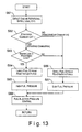
- FIG. 13 is a flow chart of the control executed in the ECU 13 of the direct fuel injection engine in accordance with the fourth embodiment of the present invention.
- Steps S61 to S63 in Figure 13 are the same as steps S1 to S3 of the first embodiment shown in Figure 5(a).
- the ECU 13 is configured to set the fuel stream penetration force to be relatively small in step S66.
- the fuel stream penetration force is set to be relatively small, a combustible first air-fuel mixture is formed in the combustion chamber 4 before the fuel stream collides against cavity 3a of the piston crown surface.
- step S67 the ECU 13 is configured to set the fuel pressure to be relatively low to achieve the relatively small fuel stream penetration force set in step S66.
- the ECU 13 is configured to set the fuel stream penetration force to be relatively large in step S64.
- the fuel stream penetration force is set to be relatively large, a combustible second air-fuel mixture after the fuel stream first collides against the cavity 3a of the piston crown surface.
- step S65 the ECU 13 is configured to set the fuel pressure to be relatively low to achieve the relatively large fuel stream penetration force set in step S64.
- step S68 the ECU 13 is configured to control the fuel stream penetration force by outputting a signal that drives the fuel injection pressure at a prescribed pressure in accordance with the fuel stream penetration force set for each regions as determined in the previous steps.
- the fuel stream penetration force is easily varied by changing the fuel pressure.
- the nozzle cross sectional area in order to reduce the penetration force of the fuel stream.
- the fuel stream penetration force is easily varied.
- the atomization of the fuel droplets can be improved when the nozzle cross sectional area is reduced.
- strengthening the swirl flow in the combustion chamber 4 can be also alternatively utilized in order to reduce the penetration force of the fuel stream. In such a case too, the fuel stream penetration force is easily varied. Moreover the mixing of the air-fuel mixture is further promoted when the swirl flow in the combustion chamber 4 is strengthened.
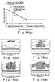
- the constitution of the direct fuel injection engine of the fifth embodiment is basically same as that of the fourth embodiment, except that the fuel injection valve 11 is a swirl type injection valve, and the fuel pump 9 is configured to control the fuel injection pressure to change the fuel injection angle of the fuel stream injected from the fuel injection valve 11.
- the fuel injection angle increases when the fuel injection pressure increases, and the fuel injection angle decreases when the fuel injection pressure decreases.
- the fuel injection pressure is increased to increase the fuel injection angle, and thus, a combustible first air-fuel mixture is formed, which is combusted before the fuel stream collides against the cavity 3a.
- the fuel injection pressure is reduced to decrease the fuel injection angle, and thus, a second air-fuel mixture is formed, which is combusted after the fuel stream collides against the cavity 3a and guided to the upper portion of the combustion chamber 4.
- Figure 14(a) is a diagrammatic chart illustrating another example of the relationship between the engine operating load and the fuel injection pressure in accordance with the fourth embodiment of the present invention.
- Figures 14(b)-14(e) are diagrammatic cross-sectional views of a combustion chamber illustrating distributions of the air-fuel mixture in the combustion chamber under various engine operating loads shown in Figure 14(a).
- the fuel injection pressure is preferably continuously varied in accordance with the engine operating load. More specifically, in the low-load stratified region A, the fuel injection pressure is set to be relatively large, and the fuel injection pressure is reduced as the load increases. Thus, the fuel injection angle in the low-load stratified combustion region A is relatively large, and the fuel injection angle decreases as the load increases. Accordingly, the first air-fuel mixture is formed during the low-load stratified combustion region A before the fuel stream collides against the cavity 3a.
- the fuel injection pressure is set to achieve a fuel injection angle with which the second combustible air-fuel mixture is formed as the fuel stream first collides against the peripheral surface of the cavity 3a and guided toward a center axis of the cavity 3a, as shown in Figure 14(c).
- the fuel stream that is guided from the cavity peripheral wall surface toward the center axis of the piston 3 continues to be oriented in the vicinity of the plug gap of the spark plug 12 to form a relatively small stratified air-fuel mixture. Accordingly, more stable combustion is accomplished when the load is relatively low in the high-load stratified combustion region B.
- the fuel injection pressure is set to achieve a fuel injection angle with which the second air-fuel mixture is formed as the fuel stream first collides against the bottom surface of the cavity 3a in the vicinity of the cavity center axis and guided toward the direction of the peripheral surface of the cavity 3a, as shown in Figure 14(d).
- the fuel stream that is guided from the vicinity of the center axis of the piston toward the direction of the peripheral wall surface of the cavity 3a continues to be oriented toward the vicinity of a plug gap of the spark plug 12 to form a relatively large stratified air-fuel mixture mass. Accordingly, a stable combustion can be accomplished in when the load is relatively high in the high-stratified combustion region B.
- the fifth embodiment of the present invention utilizes a swirl type injection valve as the fuel injection valve 11, and the fuel injection angle can be varied without complicating the structure of the fuel injection valve 11 by varying the fuel pressure (fuel injection pressure).
- the combustion chamber 4 can be arranged to have an alternate shape as shown in Figure 15(a). More specifically, the alternate shape of the combustion chamber 4 has a conically shaped guide wall (counterbore) around the perimeter of the injection valve 11 or the nozzle thereof, as shown in Figure 15(a).
- the guide wall (counterbore) is shaped so that the fuel stream exhibits almost no Coanda effect when the fuel injection angle is small (low fuel pressure, low fuel ratio, high back pressure), and exhibits a large Coanda effect when the fuel stream angle is large (high fuel pressure, high fuel ratio, low back pressure).
- the fuel injection angle can more easily be modified by effectively utilizing the Coanda effect by forming the approximately conically shaped counterbore around the perimeter of the fuel injection valve 11.
- the direct fuel injection engine of the present invention can more effectively vary the fuel injection angle by providing the guide wall (counterbore) in comparison with the shape of the combustion chamber 4 without a guide wall shown in Figure 15(b), in addition to controlling the fuel injection angle by controlling the fuel pressure, the fuel-air mass ratio, or the back pressure.
- the guide wall (counterbore) is approximately conically shaped, the Coanda effect can by utilized around the entire perimeter of the fuel stream, enabling more effective varying of the fuel injection angle.
Landscapes
- Engineering & Computer Science (AREA)
- Chemical & Material Sciences (AREA)
- Combustion & Propulsion (AREA)
- Mechanical Engineering (AREA)
- General Engineering & Computer Science (AREA)
- Combustion Methods Of Internal-Combustion Engines (AREA)
- Electrical Control Of Air Or Fuel Supplied To Internal-Combustion Engine (AREA)
- Fuel-Injection Apparatus (AREA)
Applications Claiming Priority (4)
| Application Number | Priority Date | Filing Date | Title |
|---|---|---|---|
| JP2002374874 | 2002-12-25 | ||
| JP2002374874A JP2004204775A (ja) | 2002-12-25 | 2002-12-25 | 内燃機関の燃料噴射制御装置 |
| JP2003025914 | 2003-02-03 | ||
| JP2003025914A JP4029737B2 (ja) | 2003-02-03 | 2003-02-03 | 直噴火花点火式内燃機関 |
Publications (2)
| Publication Number | Publication Date |
|---|---|
| EP1433935A2 true EP1433935A2 (de) | 2004-06-30 |
| EP1433935A3 EP1433935A3 (de) | 2006-06-28 |
Family
ID=32473732
Family Applications (1)
| Application Number | Title | Priority Date | Filing Date |
|---|---|---|---|
| EP03029237A Withdrawn EP1433935A3 (de) | 2002-12-25 | 2003-12-18 | Brennkraftmaschine mit direkter Kraftstoffeinspritzung |
Country Status (3)
| Country | Link |
|---|---|
| US (1) | US6851408B2 (de) |
| EP (1) | EP1433935A3 (de) |
| CN (1) | CN1274951C (de) |
Cited By (2)
| Publication number | Priority date | Publication date | Assignee | Title |
|---|---|---|---|---|
| EP1707783A1 (de) * | 2005-03-18 | 2006-10-04 | Nissan Motor Co., Ltd. | Steuerung direkteinspritzender Brennkraftmaschinen mit Fremdzündung |
| DE102019210551A1 (de) * | 2019-07-17 | 2021-01-21 | Robert Bosch Gmbh | Kraftstoffinjektor |
Families Citing this family (12)
| Publication number | Priority date | Publication date | Assignee | Title |
|---|---|---|---|---|
| US6832594B2 (en) * | 2002-01-09 | 2004-12-21 | Nissan Motor Co., Ltd. | Direct fuel injection engine |
| JP4244745B2 (ja) * | 2003-08-07 | 2009-03-25 | 日産自動車株式会社 | 筒内直噴式ガソリン機関 |
| JP4649142B2 (ja) * | 2004-07-30 | 2011-03-09 | トヨタ自動車株式会社 | 内燃機関の点火時期制御装置 |
| US9022003B2 (en) * | 2011-04-06 | 2015-05-05 | GM Global Technology Operations LLC | Piston for robust auto-ignition |
| JP6098489B2 (ja) * | 2013-11-25 | 2017-03-22 | マツダ株式会社 | 直噴ガソリンエンジンの制御装置 |
| JP6171959B2 (ja) * | 2014-01-30 | 2017-08-02 | マツダ株式会社 | 直噴ガソリンエンジンの制御装置 |
| DE102014205454A1 (de) * | 2014-03-24 | 2015-09-24 | Robert Bosch Gmbh | Gasinjektor mit Doppelventilnadel |
| JP6299819B2 (ja) * | 2016-08-08 | 2018-03-28 | マツダ株式会社 | 直噴エンジンの制御装置 |
| GB201717437D0 (en) * | 2017-10-24 | 2017-12-06 | Rolls Royce Plc | Apparatus and methods for controlling reciprocating internal combustion engines |
| CN107762803A (zh) * | 2017-11-22 | 2018-03-06 | 台州中际汽车零部件有限公司 | 平衡气旋高压空压机 |
| CN114060164A (zh) * | 2020-08-06 | 2022-02-18 | 广州汽车集团股份有限公司 | 一种发动机燃油喷射控制方法及装置 |
| CN116608041A (zh) * | 2023-03-28 | 2023-08-18 | 广西精磁科技有限公司 | 一种点燃式四冲程重油活塞发动机 |
Citations (1)
| Publication number | Priority date | Publication date | Assignee | Title |
|---|---|---|---|---|
| EP1369561A2 (de) | 2002-06-04 | 2003-12-10 | Nissan Motor Co., Ltd. | Direkteinspritzungsbrennkraftmaschine |
Family Cites Families (16)
| Publication number | Priority date | Publication date | Assignee | Title |
|---|---|---|---|---|
| JPH08177684A (ja) | 1994-12-26 | 1996-07-12 | Hitachi Ltd | 燃料噴射弁、及びこれを備えた内燃機関装置 |
| JPH1182028A (ja) | 1997-08-29 | 1999-03-26 | Toyota Motor Corp | 筒内噴射式火花点火内燃機関 |
| JP3147092B2 (ja) * | 1998-07-10 | 2001-03-19 | トヨタ自動車株式会社 | 内燃機関 |
| JP2000303936A (ja) | 1999-04-22 | 2000-10-31 | Toyota Motor Corp | 燃料噴射ノズル |
| JP4253426B2 (ja) * | 1999-09-14 | 2009-04-15 | 日産自動車株式会社 | 圧縮自己着火式ガソリン機関 |
| DE60015885T2 (de) * | 1999-09-17 | 2005-03-17 | Nissan Motor Co., Ltd., Yokohama | Benzinbrennkraftmaschine mit Verdichtungszündung |
| JP3815163B2 (ja) * | 2000-01-25 | 2006-08-30 | 日産自動車株式会社 | 圧縮自己着火式内燃機関 |
| EP1134400B1 (de) * | 2000-01-27 | 2012-01-18 | Nissan Motor Company Limited | Regelung von selbstzündender Verbrennung in einer Brennkraftmaschine |
| JP3920526B2 (ja) * | 2000-03-08 | 2007-05-30 | トヨタ自動車株式会社 | 火花点火式成層燃焼内燃機関 |
| JP4134492B2 (ja) * | 2000-06-08 | 2008-08-20 | 三菱自動車工業株式会社 | 筒内噴射型内燃機関 |
| JP3852310B2 (ja) * | 2000-08-07 | 2006-11-29 | トヨタ自動車株式会社 | 筒内噴射式火花点火内燃機関 |
| JP3945152B2 (ja) * | 2000-11-21 | 2007-07-18 | 日産自動車株式会社 | 内燃機関の燃焼制御装置 |
| JP3952693B2 (ja) * | 2001-01-09 | 2007-08-01 | 日産自動車株式会社 | 筒内直接燃料噴射式火花点火エンジンの燃料噴射制御装置 |
| JP2002332934A (ja) * | 2001-05-10 | 2002-11-22 | Toyota Motor Corp | 燃料噴射弁 |
| JP2002339789A (ja) * | 2001-05-16 | 2002-11-27 | Mazda Motor Corp | 火花点火式直噴エンジンの制御装置および燃料噴射時期設定方法 |
| JP3975702B2 (ja) * | 2001-08-02 | 2007-09-12 | 日産自動車株式会社 | 自己着火式エンジンの制御装置 |
-
2003
- 2003-10-28 US US10/694,013 patent/US6851408B2/en not_active Expired - Fee Related
- 2003-12-18 EP EP03029237A patent/EP1433935A3/de not_active Withdrawn
- 2003-12-25 CN CNB2003101235858A patent/CN1274951C/zh not_active Expired - Fee Related
Patent Citations (1)
| Publication number | Priority date | Publication date | Assignee | Title |
|---|---|---|---|---|
| EP1369561A2 (de) | 2002-06-04 | 2003-12-10 | Nissan Motor Co., Ltd. | Direkteinspritzungsbrennkraftmaschine |
Cited By (4)
| Publication number | Priority date | Publication date | Assignee | Title |
|---|---|---|---|---|
| EP1707783A1 (de) * | 2005-03-18 | 2006-10-04 | Nissan Motor Co., Ltd. | Steuerung direkteinspritzender Brennkraftmaschinen mit Fremdzündung |
| US7234437B2 (en) | 2005-03-18 | 2007-06-26 | Nissan Motor Co., Ltd. | Direct-injection internal combustion engine and combustion method therefor |
| DE102019210551A1 (de) * | 2019-07-17 | 2021-01-21 | Robert Bosch Gmbh | Kraftstoffinjektor |
| US12234795B2 (en) | 2019-07-17 | 2025-02-25 | Robert Bosch Gmbh | Fuel injector |
Also Published As
| Publication number | Publication date |
|---|---|
| CN1510257A (zh) | 2004-07-07 |
| EP1433935A3 (de) | 2006-06-28 |
| CN1274951C (zh) | 2006-09-13 |
| US20040123833A1 (en) | 2004-07-01 |
| US6851408B2 (en) | 2005-02-08 |
Similar Documents
| Publication | Publication Date | Title |
|---|---|---|
| EP1857654B1 (de) | Verbrennungsmotor | |
| EP1134400B1 (de) | Regelung von selbstzündender Verbrennung in einer Brennkraftmaschine | |
| US6668792B2 (en) | Control system for in-cylinder direct injection engine | |
| US6814046B1 (en) | Direct fuel injection engine | |
| KR100556648B1 (ko) | 실린더 내부 직접분사 불꽃점화 엔진 | |
| US6851408B2 (en) | Direct fuel injection engine | |
| JP2003534495A (ja) | 燃料噴射システム | |
| US20030221658A1 (en) | Direct fuel injection internal combustion engine | |
| EP2138683A1 (de) | Verbrennungsmotor und Steuerverfahren dafür | |
| US7028662B2 (en) | Direct fuel injection engine | |
| JP2000104551A (ja) | 直接噴射ガソリンエンジン | |
| EP1837504B1 (de) | Verbrennungsmotor mit fremdzündung und direkteinspritzung | |
| EP1832741A2 (de) | Verbrennungsmotor mit Direkteinspritzung | |
| US7104249B2 (en) | Direct fuel injection/spark ignition engine control device | |
| EP0237065B1 (de) | Brennkammer für Brennkraftmaschinen | |
| JP3921732B2 (ja) | 筒内噴射型火花点火式エンジン | |
| JP3767125B2 (ja) | 筒内噴射式内燃機関のピストン | |
| JP2002155748A (ja) | 筒内噴射式火花点火内燃機関 | |
| JPH11182248A (ja) | 筒内噴射式エンジンの燃焼室構造 | |
| EP4063636B1 (de) | Motorsystem | |
| JP2006046276A (ja) | 直噴火花点火式内燃機関の点火制御装置 | |
| JP2005140006A (ja) | 筒内直接噴射式内燃機関 | |
| JP2004251143A (ja) | 直噴火花点火式内燃機関の燃焼制御装置 | |
| JP4122890B2 (ja) | 直噴火花点火式内燃機関 | |
| JP2004204775A (ja) | 内燃機関の燃料噴射制御装置 |
Legal Events
| Date | Code | Title | Description |
|---|---|---|---|
| PUAI | Public reference made under article 153(3) epc to a published international application that has entered the european phase |
Free format text: ORIGINAL CODE: 0009012 |
|
| 17P | Request for examination filed |
Effective date: 20031218 |
|
| AK | Designated contracting states |
Kind code of ref document: A2 Designated state(s): AT BE BG CH CY CZ DE DK EE ES FI FR GB GR HU IE IT LI LU MC NL PT RO SE SI SK TR |
|
| AX | Request for extension of the european patent |
Extension state: AL LT LV MK |
|
| PUAL | Search report despatched |
Free format text: ORIGINAL CODE: 0009013 |
|
| AK | Designated contracting states |
Kind code of ref document: A3 Designated state(s): AT BE BG CH CY CZ DE DK EE ES FI FR GB GR HU IE IT LI LU MC NL PT RO SE SI SK TR |
|
| AX | Request for extension of the european patent |
Extension state: AL LT LV MK |
|
| AKX | Designation fees paid |
Designated state(s): DE FR GB |
|
| 17Q | First examination report despatched |
Effective date: 20081106 |
|
| STAA | Information on the status of an ep patent application or granted ep patent |
Free format text: STATUS: THE APPLICATION IS DEEMED TO BE WITHDRAWN |
|
| 18D | Application deemed to be withdrawn |
Effective date: 20110701 |