EP1433935A2 - Direct fuel injection engine - Google Patents
Direct fuel injection engine Download PDFInfo
- Publication number
- EP1433935A2 EP1433935A2 EP03029237A EP03029237A EP1433935A2 EP 1433935 A2 EP1433935 A2 EP 1433935A2 EP 03029237 A EP03029237 A EP 03029237A EP 03029237 A EP03029237 A EP 03029237A EP 1433935 A2 EP1433935 A2 EP 1433935A2
- Authority
- EP
- European Patent Office
- Prior art keywords
- fuel injection
- fuel
- injection engine
- direct
- air
- Prior art date
- Legal status (The legal status is an assumption and is not a legal conclusion. Google has not performed a legal analysis and makes no representation as to the accuracy of the status listed.)
- Withdrawn
Links
Images


Classifications
-
- F—MECHANICAL ENGINEERING; LIGHTING; HEATING; WEAPONS; BLASTING
- F02—COMBUSTION ENGINES; HOT-GAS OR COMBUSTION-PRODUCT ENGINE PLANTS
- F02D—CONTROLLING COMBUSTION ENGINES
- F02D13/00—Controlling the engine output power by varying inlet or exhaust valve operating characteristics, e.g. timing
- F02D13/02—Controlling the engine output power by varying inlet or exhaust valve operating characteristics, e.g. timing during engine operation
- F02D13/0203—Variable control of intake and exhaust valves
- F02D13/0215—Variable control of intake and exhaust valves changing the valve timing only
-
- F—MECHANICAL ENGINEERING; LIGHTING; HEATING; WEAPONS; BLASTING
- F02—COMBUSTION ENGINES; HOT-GAS OR COMBUSTION-PRODUCT ENGINE PLANTS
- F02B—INTERNAL-COMBUSTION PISTON ENGINES; COMBUSTION ENGINES IN GENERAL
- F02B17/00—Engines characterised by means for effecting stratification of charge in cylinders
- F02B17/005—Engines characterised by means for effecting stratification of charge in cylinders having direct injection in the combustion chamber
-
- F—MECHANICAL ENGINEERING; LIGHTING; HEATING; WEAPONS; BLASTING
- F02—COMBUSTION ENGINES; HOT-GAS OR COMBUSTION-PRODUCT ENGINE PLANTS
- F02B—INTERNAL-COMBUSTION PISTON ENGINES; COMBUSTION ENGINES IN GENERAL
- F02B23/00—Other engines characterised by special shape or construction of combustion chambers to improve operation
- F02B23/08—Other engines characterised by special shape or construction of combustion chambers to improve operation with positive ignition
- F02B23/10—Other engines characterised by special shape or construction of combustion chambers to improve operation with positive ignition with separate admission of air and fuel into cylinder
- F02B23/101—Other engines characterised by special shape or construction of combustion chambers to improve operation with positive ignition with separate admission of air and fuel into cylinder the injector being placed on or close to the cylinder centre axis, e.g. with mixture formation using spray guided concepts
-
- F—MECHANICAL ENGINEERING; LIGHTING; HEATING; WEAPONS; BLASTING
- F02—COMBUSTION ENGINES; HOT-GAS OR COMBUSTION-PRODUCT ENGINE PLANTS
- F02D—CONTROLLING COMBUSTION ENGINES
- F02D41/00—Electrical control of supply of combustible mixture or its constituents
- F02D41/30—Controlling fuel injection
- F02D41/3011—Controlling fuel injection according to or using specific or several modes of combustion
- F02D41/3017—Controlling fuel injection according to or using specific or several modes of combustion characterised by the mode(s) being used
- F02D41/3023—Controlling fuel injection according to or using specific or several modes of combustion characterised by the mode(s) being used a mode being the stratified charge spark-ignited mode
- F02D41/3029—Controlling fuel injection according to or using specific or several modes of combustion characterised by the mode(s) being used a mode being the stratified charge spark-ignited mode further comprising a homogeneous charge spark-ignited mode
-
- Y—GENERAL TAGGING OF NEW TECHNOLOGICAL DEVELOPMENTS; GENERAL TAGGING OF CROSS-SECTIONAL TECHNOLOGIES SPANNING OVER SEVERAL SECTIONS OF THE IPC; TECHNICAL SUBJECTS COVERED BY FORMER USPC CROSS-REFERENCE ART COLLECTIONS [XRACs] AND DIGESTS
- Y02—TECHNOLOGIES OR APPLICATIONS FOR MITIGATION OR ADAPTATION AGAINST CLIMATE CHANGE
- Y02T—CLIMATE CHANGE MITIGATION TECHNOLOGIES RELATED TO TRANSPORTATION
- Y02T10/00—Road transport of goods or passengers
- Y02T10/10—Internal combustion engine [ICE] based vehicles
- Y02T10/12—Improving ICE efficiencies
Definitions
- the present invention generally relates to a spark ignition internal combustion engine with direct fuel injection. More specifically, the present invention relates to a spark ignition internal combustion engine with direct fuel injection that achieves an improved combustibility of the fuel during stratified combustion.
- a spark ignition internal combustion engine with direct fuel injection is configured and arranged to perform a highly lean combustion by directly injecting a fuel into a cylinder from a fuel injection valve and forming a stratified air-fuel mixture in the cylinder during spark ignition combustion.
- the fuel consumption can be significantly reduced, particularly when the engine is operating under low and medium loads.
- An appropriate stratified air-fuel mixture can be formed in the cylinder by providing a bowl-shaped cavity on a piston, setting a fuel stream injected from the fuel injection valve to collide against a wall surface of the bowl-shaped cavity, and forming a fuel stream circulation along the wall surface of the bowl-shaped cavity.
- Japanese Laid-Open Patent Publication No. 11-82028 discloses a direct fuel injection spark ignition internal combustion engine that forms an appropriate stratified air-fuel mixture in a cylinder by disposing the fuel injection valve in the vicinity directly above the cavity, setting the fuel stream to collide against the cavity perimeter wall surface, and thereby forming a fuel stream circulation toward the center part of the cavity.
- the present invention considers the abovementioned problems, and has the object to enable forming of an air-fuel mixture mass of an appropriate air-fuel ratio and size according to the operating conditions of the engine in a combustion chamber having a fixed-volume cavity.
- a direct fuel injection engine that basically comprises a combustion chamber, a spark plug, a fuel injection valve, a piston and a controller.
- the spark plug is positioned in an upper surface of the combustion chamber.
- the fuel injection valve is positioned in a substantially center portion of the upper surface of the combustion chamber, the fuel injection valve being configured and arranged to directly inject a fuel stream inside the combustion chamber.
- the piston has a guide wall surface being configured and arranged to guide the fuel stream injected from the fuel injection valve.
- the controller is configured and arranged to control operations of the spark plug and the fuel injection valve.
- the controller is further configured and arranged to ignite a first air-fuel mixture formed directly after the fuel stream is injected from the fuel injection valve and prior to a majority of the fuel stream being guide by the guide wall surface of the piston when the direct fuel injection engine is operating in a low-load stratified combustion region.
- the controller is further configured and arranged to ignite a second air-fuel mixture formed after a majority of the fuel stream is guided to an upper portion of the combustion chamber by the guide wall surface of the piston when the direct fuel injection engine is operating in a high-load stratified combustion region.
- Figure 1 is a partial cross-sectional view of an injection portion of a direct fuel injection spark ignition internal combustion engine in accordance with a first embodiment of the present invention
- Figure 2 is a partial cross-sectional view of one example of a fuel injection valve with a controllable fuel injection angle in accordance with the first embodiment of the present invention
- Figure 3 is a partial cross-sectional view of another example of a fuel injection valve with a controllable fuel injection angle in accordance with the first embodiment of the present invention
- Figure 4(a) is a diagrammatic chart illustrating the relationship between the engine operating load and the fuel stream angle in accordance with the first embodiment of the present invention
- Figure 4(b) is a diagrammatic cross-sectional view of a combustion chamber illustrating distribution of the air-fuel mixture in the combustion chamber under a low-load stratified combustion region shown as "A" in Figure 4(a);
- Figure 4(c) is a diagrammatic cross-sectional view of a combustion chamber illustrating distribution of the air-fuel mixture in the combustion chamber under a high-load stratified combustion region shown as "B" in Figure 4(a);
- Figure 4(d) is a diagrammatic cross-sectional view of a combustion chamber illustrating distributions of the air-fuel mixture in the combustion chamber under a homogeneous combustion region shown as "C" in Figure 4(a);
- Figure 5(a) is a flow chart of the control executed in a controller of the direct fuel injection engine in accordance with the first embodiment of the present invention
- Figure 5(b) is a flow chart of an alternate control executed in the controller of the direct fuel injection engine in accordance with the first embodiment of the present invention
- Figure 6 is a partial cross-sectional view of an injection portion of a direct fuel injection spark ignition internal combustion engine in accordance with a second embodiment of the present invention.
- Figure 7(a) is a diagrammatic chart illustrating the relationship between the engine operating load and the injected fuel mass ratio to the air in accordance with the second embodiment of the present invention
- Figure 7(b) is a diagrammatic cross-sectional view of a combustion chamber illustrating distribution of the air-fuel mixture in the combustion chamber under a low-load stratified combustion region shown as "A" in Figure 7(a);
- Figure 7(c) is a diagrammatic cross-sectional view of a combustion chamber illustrating distribution of the air-fuel mixture in the combustion chamber under a high-load stratified combustion region shown as "B" in Figure 7(a);
- Figure 7(d) is a diagrammatic cross-sectional view of a combustion chamber illustrating distributions of the air-fuel mixture in the combustion chamber under a homogeneous combustion region shown as "C" in Figure 7(a);
- Figure 8 is a flow chart of the control executed in a controller of the direct fuel injection engine in accordance with the second embodiment of the present invention.
- Figure 9(a) is a diagrammatic chart illustrating one example of the relationship between the engine operating load and the intake valve close timing in accordance with a third embodiment of the present invention.
- Figure 9(b) is a diagrammatic cross-sectional view of a combustion chamber illustrating distribution of the air-fuel mixture in the combustion chamber under a low-load stratified combustion region shown as "A" in Figure 9(a);
- Figure 9(c) is a diagrammatic cross-sectional view of a combustion chamber illustrating distribution of the air-fuel mixture in the combustion chamber under a high-load stratified combustion region shown as "B1" in Figure 9(a);
- Figure 9(d) is a diagrammatic cross-sectional view of a combustion chamber illustrating distribution of the air-fuel mixture in the combustion chamber under a high-load stratified combustion region shown as "B2" in Figure 9(a);
- Figure 9(e) is a diagrammatic cross-sectional view of a combustion chamber illustrating distributions of the air-fuel mixture in the combustion chamber under a homogeneous combustion region shown as "C" in Figure 9(a);
- Figure 10(a) is a diagrammatic chart illustrating another example of the relationship between the engine operating load and the intake valve close timing in accordance with the third embodiment of the present invention.
- Figure 10(b) is a diagrammatic cross-sectional view of a combustion chamber illustrating distribution of the air-fuel mixture in the combustion chamber under a low-load stratified combustion region shown as "A" in Figure 10(a);
- Figure 10(c) is a diagrammatic cross-sectional view of a combustion chamber illustrating distribution of the air-fuel mixture in the combustion chamber under a high-load stratified combustion region shown as "B" in Figure 10(a);
- Figure 10(d) is a diagrammatic cross-sectional view of a combustion chamber illustrating distributions of the air-fuel mixture in the combustion chamber under a homogeneous combustion region shown as "C" in Figure 10(a);
- Figure 11 is a flow chart of the control executed in a controller of the direct fuel injection engine in accordance with the third embodiment of the present invention.
- Figure 12(a) is a diagrammatic chart illustrating one example of the relationship between the engine operating load and the fuel pressure in accordance with a fourth embodiment of the present invention.
- Figure 12(b) is a diagrammatic cross-sectional view of a combustion chamber illustrating distribution of the air-fuel mixture in the combustion chamber under a low-load stratified combustion region shown as "A" in Figure 12(a);
- Figure 12(c) is a diagrammatic cross-sectional view of a combustion chamber illustrating distribution of the air-fuel mixture in the combustion chamber under a high-load stratified combustion region shown as "B" in Figure 12(a);
- Figure 12(d) is a diagrammatic cross-sectional view of a combustion chamber illustrating distributions of the air-fuel mixture in the combustion chamber under a homogeneous combustion region shown as "C" in Figure 12(a);
- Figure 13 is a flow chart of the control executed in a controller of the direct fuel injection engine in accordance with the fourth embodiment of the present invention.
- Figure 14(a) is a diagrammatic chart illustrating another example of the relationship between the engine operating load and the fuel injection pressure in accordance with the fifth embodiment of the present invention.
- Figure 14(b) is a diagrammatic cross-sectional view of a combustion chamber illustrating distribution of the air-fuel mixture in the combustion chamber under a low-load stratified combustion region shown as "A" in Figure 14(a);
- Figure 14(c) is a diagrammatic cross-sectional view of a combustion chamber illustrating distribution of the air-fuel mixture in the combustion chamber under a high-load stratified combustion region shown as "B1' " in Figure 14(a);
- Figure 14(d) is a diagrammatic cross-sectional view of a combustion chamber illustrating distributions of the air-fuel mixture in the combustion chamber under a homogeneous combustion region shown as "B2' " in Figure 14(a);
- Figure 14(e) is a diagrammatic cross-sectional view of a combustion chamber illustrating distributions of the air-fuel mixture in the combustion chamber under a homogeneous combustion region shown as "C" in Figure 14(a);
- Figure 15(a) is a diagrammatic view of the combustion chamber illustrating an air-fuel mixture distribution with a counterbore in the vicinity of the fuel injection valve;
- Figure 15(a) and 15(b) is a diagrammatic view of the combustion chamber illustrating an air-fuel mixture distribution without a counterbore in the vicinity of the fuel injection valve.
- FIG. 1 is a partial cross-sectional view of an injection portion of the direct fuel injection engine of the first embodiment.
- the injection portion of the direct fuel injection engine includes a cylinder head 1, a cylinder block 2, a piston 3, at least one intake valve 5, at least one exhaust valve 6, at least one intake port 7, at least one exhaust port 8, a fuel injection valve 11 and a spark plug 12.
- a combustion chamber 4 is basically defined by the cylinder head 1, the cylinder block 2 and the piston 3.
- a fuel pump 9 is disposed at the end of the camshaft which drives the intake valve 5.
- the fuel pump 9 can be arranged to be driven by a separately arranged electric motor.
- a variably valve timing mechanism 5a is preferably used to control a valve timing of the intake cam. Variably valve timing mechanism are well known in the art, and thus, the variably valve timing mechanism 5a will not be discussed or illustrated in detail herein.
- the fuel injection valve 11 is positioned in a substantially center portion of an upper surface of the combustion chamber 4.
- the fuel injection valve 11 is preferably centered or substantially centered on the center longitudinal axis of the piston 3.
- the fuel injection valve 11 is configured and arranged to inject the fuel pressurized by the fuel pump 9 and conveyed via a fuel conduit 10 into the combustion chamber 4.
- the fuel injection valve 11 is preferably configured and arranged such that the fuel stream injected from the fuel injection valve 11 spreads in a substantially conical shape in the combustion chamber 4.
- the fuel injection valve 11 is configured and arranged to inject a fuel stream in at least two different fuel injection angles, i.e., angles of an apex of the conical-shaped fuel stream, by changing a lift of a needle valve of the fuel injection valve 11.
- the fuel injection valve 11 utilizing a needle valve is disclosed in Japanese Laid Open Patent Publication No. H8-177684.
- the fuel injection valve 11 includes a needle valve 11A and a valve body 11B in which the needle valve 11A is inserted.
- the valve body 11B also includes a nozzle hole 11C.
- a fuel passageway 11a is formed in the valve body 11B.
- the downstream end of the fuel passageway 11a is branched into a lower side wide angle spout 11b and a narrow angle spout 11c.
- the wide angle spout 11b is arranged to be perpendicular to the axial direction of the needle valve 11A.
- the narrow angle spout 11c is inclined downwardly toward the nozzle hole 11C.
- the swirl of the fuel spouted from the wide angle spout 11b is weakened by the force of the fuel flow spouted from the downwardly inclined narrow angle spout 11c toward the nozzle hole 11C.
- the fuel injection angle of the fuel stream injected from the fuel injection valve 11 is smaller than the fuel injection angle of the fuel stream injected from the fuel injection valve 11 when the lift of the needle valve 11A is small.
- the injection angle of the conically spreading fuel stream from the nozzle hole 11C increases comparatively when the lift of the needle valve 11A is small, opening only the wide angle spout 11b, and decreases comparatively when the lift of the needle valve 11A is large, opening both the wide angle spout 11b and the narrow angle spout 11c.
- a fuel injection valve 11' can be substituted with the fuel injection valve 11 in the direct fuel injection engine of the first embodiment. More specifically, the fuel injection valve 11' is configured and arranged as disclosed in Japanese Laid Open Patent Publication No. 2000-303936. As shown in Figure 3, the fuel injection valve 11' basically comprises a needle valve 11D and a valve body 11E. A T-shaped fuel passageway 11d is formed in the needle valve 11D. An upper narrow angle nozzle 11e and a lower wide angle nozzle 11f are formed in a valve body 11E. The upper narrow angle nozzle 11e has a large downwardly angled injection angle, and the lower wide angle nozzle 11f has a small downwardly angled injection angle.
- the injection angle is comparatively large when the lift of the needle valve 11D is small, opening only the wide angle nozzle 11f, and is relatively small when the lift of the needle valve 11D is large, opening both the wide angle nozzle 11f and the narrow angle nozzle 11e.
- any construction of the fuel injection valve 11 is not limited to the above mentioned examples. Rather, any construction of the fuel injection valve 11 can be utilized provided that the fuel injection valve 11 is adopted to carry out the same functions in the present invention. More specifically, in the first embodiment of the present invention, any construction of the fuel injection valve 11 can be utilized as long as the fuel injection valve 11 is arranged to inject the fuel into the combustion chamber 4 in at least two different fuel injection angles.
- the piston 3 of the direct fuel injection engine includes a bowl-shaped cavity 3a on the piston crown surface which is a position opposite the fuel injection valve 11.
- the fuel injected from the fuel injection valve 11 principally forms a stratified air-fuel mixture mass within the cavity 3a and in the upper space of the cavity 3a.
- the cavity 3a is defined by a guide wall surface comprising a bottom surface and a peripheral wall surface that curves upwardly from the bottom surface of the cavity 3a and is angled inwardly towards the center axis of the piston 3 at its upper end section.
- the bottom surface and the peripheral wall surface of the cavity 3a are shaped so that the fuel stream collided against the cavity 3a is oriented toward the substantially upper center part of the combustion chamber 4, which includes the spark plug 12.
- the shape of the peripheral wall surface of the cavity 3a is curved generally toward the fuel injection valve 11, and formed so that the edge peripheral wall surface is oriented at an angle formed between the cylinder axis and the approximate direction in which the fuel stream is injected from the fuel injection valve 11.
- the fuel stream collided against the cavity 3a wall spreads outwardly beyond the outer edge of the initial fuel stream from the fuel injection valve 11 to the outside of the cavity 3a, but the spread can be accumulated on the approximately inner side of the space above the cavity 3a, and it is possible to form the stratified combustible air-fuel mixture because excessive diffusion of the air-fuel mixture is suppressed.
- the spark plug 12 is configured and arranged to ignite and combust the air-fuel mixture. As seen in Figure 1, the spark plug 12 is positioned in the upper surface of the combustion chamber 4 and is located adjacent the fuel injection valve 11.
- the direct fuel injection engine of the present invention is controlled in an integrated manner by a controller or engine control unit (ECU) 13. Moreover, the direct fuel injection engine of the present invention includes various sensors that monitor an operating condition of the vehicle, such as a crank angle sensor, a cooling water temperature sensor and a throttle opening sensor. More specifically, a crank angle sensor signal, a cooling water temperature signal, and a throttle opening signal are input to the ECU 13, and the ECU 13 is configured to perform the above mentioned various control functions, such as control of the needle valve 11A of the fuel injection valve 11 and control of the spark plug 12, based the above mentioned input signals.
- various sensors that monitor an operating condition of the vehicle, such as a crank angle sensor, a cooling water temperature sensor and a throttle opening sensor. More specifically, a crank angle sensor signal, a cooling water temperature signal, and a throttle opening signal are input to the ECU 13, and the ECU 13 is configured to perform the above mentioned various control functions, such as control of the needle valve 11A of the fuel injection valve 11 and control of the spark plug 12, based the
- the ECU 13 preferably includes a microcomputer with a control program that controls the direct fuel injection engine as discussed below.
- the ECU 13 can also include other conventional components such as an input interface circuit, an output interface circuit, and storage devices such as a ROM (Read Only Memory) device and a RAM (Random Access Memory) device.
- the microcomputer of the ECU 13 is programmed to control the direct fuel injection engine.
- the memory circuit stores processing results and control programs that are run by the processor circuit.
- the ECU 13 is operatively coupled to the various components of the direct fuel injection engine in a conventional manner.
- the internal RAM of the ECU 13 stores statuses of operational flags and various control data.
- the ECU 13 is capable of selectively controlling any of the components of the control system in accordance with the control program.
- the direct fuel injection engine of the present invention is configured and arranged to perform combustion of the air-fuel mixture in a stratified combustion mode or a homogeneous combustion mode depending on an operating condition of the direct fuel injection engine.
- a stratified combustion mode a relatively small amount of fuel is injected during a compression stroke (particularly in the latter half of the compression stroke) to form a stratified fuel-air mixture mass to improve fuel economy through lean operation. Since the stratified fuel-air mixture is formed with the surrounding area in the combustion chamber 4 being occupied by air, stable combustion is accomplished even with the relatively small amount of fuel.
- the fuel is injected during an intake stroke (particularly in the former half of the intake stroke) to perform a stoichiometric operation (stoichiometric air-fuel ratio operation).
- a stoichiometric operation stoichiometric air-fuel ratio operation.
- Figure 4(a) is a diagrammatic chart showing the relationship between the operating condition (load) and the fuel injection angle of the fuel stream injected from the fuel injection valve 11.
- Figures 4(b)-4(d) show the distribution of the air-fuel mixture in the combustion chamber 4 under various operating loads with the reference to the loads shown in Figure 4(a).
- the operating load is generally divided into a low-load stratified combustion region shown as "A" in Figure 4(a), a high-load stratified combustion region shown as "B” in Figure 4(a), and a homogeneous combustion region shown as "C” in Figure 4(a).
- A low-load stratified combustion region
- B high-load stratified combustion region
- C homogeneous combustion region
- the amount of fuel injected during the low-load stratified combustion region A is small. If the fuel injection angle is set to be relatively small so that the injected fuel stream collides against the wall surface of the cavity 3a, the fuel stream will be highly diffused in the cavity 3a and above the cavity 3a.
- the fuel injection valve 11 is configured and arranged to set the fuel injection angle such that a combustible air-fuel mixture is formed in the combustion chamber 4 before the fuel stream collides against the cavity 3a in the low-load stratified combustion region A. More specifically, the fuel injection valve 11 is configured and arranged to set the injection angle of the fuel stream to be relatively large in the low-load stratified combustion region A as seen in Figure 4(a).
- a first air-fuel mixture that is close to stoichiometric state is formed in the upper center portion of the combustion chamber 4 where the spark plug 12 is located before the fuel stream collides against the wall surface of the cavity 3a, as shown in Figure 4(b).
- the first air-fuel mixture is a combustible air-fuel mixture that is close to the stoichiometric state formed in the combustion chamber 4 relatively immediately after the fuel stream is injected from the fuel injection valve 11.
- the first air-fuel mixture has a superior ignitability and combustion stability in the low-load stratified combustion region A.
- the fuel stream injected from the fuel injection valve 11 is arranged to directly reach a plug gap of the spark plug 12 and form the first air-fuel mixture in the upper portion of the combustion chamber 4 in the low-load stratified combustion region A.
- the spark plug 12 is configured and arranged to ignite the first air-fuel mixture relatively immediately after the fuel is injected from the fuel injection valve 11 when the direct fuel injection engine is operating in the low-load stratified combustion region A.
- the amount of the fuel injected from the fuel injection valve 11 in the high-load stratified combustion region B is larger than the amount of fuel injected in the low-load stratified combustion region A.
- the fuel injection angle is set relatively small under the high-load stratified combustion region B. Accordingly, the fuel stream collides against the wall surface of the cavity 3a, and becomes highly diffused in the cavity 3a and the upper space of the cavity 3a, as seen in Figure 4(c).
- a second air-fuel mixture that is close to a stoichiometric state can be formed after the fuel stream collides against the cavity 3a in the high-load stratified combustion region B.
- the second air-fuel mixture is a combustible air-fuel mixture close to the stoichiometric state formed after the fuel stream injected from the fuel injection valve 11 collides against the cavity 3a and is guided toward the upper portion of the combustion chamber 4.
- the second air-fuel mixture is formed within the cavity 3a and thereabove where the spark plug 12 is located and_has a superior ignitability and combustion stability.
- the fuel stream injected from the fuel injection valve 11 is arranged to reach the spark plug 12 and form the second air-fuel mixture after the fuel stream collides against the cavity 3a and is guided toward the upper portion of the combustion chamber 4.
- the spark plug 12 is configured and arranged to ignite the second air-fuel mixture after the fuel stream collides the wall surface of the cavity 3a and the fuel stream is guided to the upper portion of the combustion chamber 4 by the wall surface of the cavity 3a when the internal combustion engine is operating in a high-load stratified combustion region B. Since the fuel stream is not directly oriented toward the spark plug 12 after the fuel stream is injected from the fuel injection valve 11, the wet fouling or dry fouling of the spark plug 12 is prevented.
- the fuel injection angle in the homogeneous combustion mode is preferably set to a relatively large angle as shown in Figure 4(a).
- the fuel injection angle in the homogeneous combustion region C is not limited to the angle shown in Figure 4(a). Rather, the fuel injection angle in the homogeneous combustion region C can be set to any angle as long as the air-fuel mixture that achieves the homogeneous combustion can be formed in the combustion chamber 4 as shown in Figure 4(d) to carry out the present invention.
- the fuel injection angle of the fuel stream injected from the fuel injection valve 11 is controlled in accordance with the load of the direct fuel injection engine.
- the load is relatively low, the diffusion of the fuel stream is suppressed and a comparatively small air-fuel mixture mass is formed by forming the combustible first air-fuel mixture before the fuel stream collides against the wall surface of the cavity 3a.
- the load is relatively high, the diffusion and mixing of the fuel stream is promoted as the fuel stream hits the wall surface of the cavity 3a and is guided toward the upper space of the cavity 3a.
- the comparatively large second air-fuel mixture mass is formed from the interior to the exterior of the cavity 3a. Therefore, the fuel can be effectively combusted under a broad range of engine operation conditions.
- a control flow executed by the ECU 13 is shown in Figure 5(a) in accordance with the first embodiment of the present invention.
- the direct fuel injection engine of the first embodiment is basically configured and arranged to control the fuel injection angle of the fuel stream, and the size of the air-fuel mixture mass in the combustion chamber 4 such that the spark plug 12 ignites the first air-fuel mixture directly after the fuel is injected from the fuel injection valve 11 in the low-load stratified combustion region A, and the spark plug 12 ignites the second air-fuel mixture after the fuel stream is guided to the upper portion of the combustion chamber by the cavity 3a in the high-load stratified combustion region B.
- Step S1 in Figure 5(a) the ECU 13 is configured to detect the rotational speed and load of the direct fuel injection engine based on input signals from the crank angle sensor, the throttle opening sensor, and the like.
- step S2 the ECU 13 is configured to determine whether to perform stratified combustion mode or homogeneous combustion mode based on the operating condition of the direct fuel injection engine determined based on the signals obtained in step S1.
- the determination of the combustion mode is made based on a previously stored table containing entries derived by empirically examining the relationship between the rotational speed and load, and the combustion mode. If a determination was made in step S2 to perform the homogeneous combustion mode, then the procedure proceeds to step S6.
- step S3 the ECU 13 is configured to determine whether the load of the direct fuel injection engine is greater than or equal to a prescribed load. More specifically, the prescribed load is a threshold value used to decide whether the internal combustion engine is operating in the low-load stratified combustion region A or the high-load stratified combustion region B.
- the prescribed load is preferably derived empirically and prestored in the ECU 13.
- the ECU 13 is configured to select, in accordance with the load of the direct fuel injection engine, whether to form a combustible first air-fuel mixture before the fuel stream collides against the cavity 3a on the piston crown surface, or to form a combustible second air-fuel mixture after the fuel stream collides against the cavity 3a on piston crown surface.
- the fuel injection angle is set to be relatively large.
- step S3 if the engine load is greater than or equal to the prescribed load in step S3, then the procedure proceeds to step S4. If the engine load is smaller than the prescribed load in step S3, then the procedure proceeds to step S6.
- step S4 the ECU 13 is configured to select a relatively small fuel injection angle.
- step S5 the ECU 13 is configured to select a large lift of the needle valve 11A to achieve the relatively small fuel injection angle.
- step S6 the ECU 13 is configured to select a relatively large fuel injection angle.
- step S7 the ECU 13 is configured to select a small lift of the needle valve 11A to achieve a relatively large fuel injection angle.
- step S8 the ECU 13 is configured to control the fuel injection angle by outputting a signal that drives the needle valve 11A to lift by a predetermined amount in accordance with an injection parameter determined in steps S5 or S7.
- the ECU 13 can be configured to control other fuel injection parameters including, but not limited to, outputting a signal that drives to the fuel pump 9, which supplies a prescribed fuel pressure.
- control of the direct fuel injection engine of the present invention can be implemented by referencing tables containing the fuel injection timing, fuel injection quantity, and fuel injection angle, which are assigned beforehand for each operating condition. These tables are preferably empirically derived beforehand.
- step S1' in Figure 5(b) the ECU 13 is configured to detect the rotational speed and load of the direct fuel injection engine based on signals from the crank angle sensor, throttle opening sensor, and the like.
- the ECU 13 is configured to read in the tables wherein the fuel injection timing, fuel injection quantity, and fuel injection angle based on engine operating conditions are prestored. Based on the values set in the tables, the ECU 13 is configured to select, in accordance with the engine load, whether to directly orient the fuel stream toward the vicinity of the spark plug gap, or to form a combustible air-fuel mixture after first colliding against the piston crown surface. More specifically, the ECU 13 is configured to increase the fuel injection angle when orienting the fuel stream directly toward the vicinity of the spark plug gap, and decrease the fuel injection angle when forming a combustible second air-fuel mixture after the fuel stream collides against the cavity 3a of the piston crown surface.
- step S3' in accordance with injection parameters decided in a previous step, the ECU 13 is configured to control the fuel injection by at least outputting a signal that drives the needle valve 11A of the fuel injection valve 11, and the fuel pump 9, which supplies a prescribed fuel pressure.
- a compact first air-fuel mixture mass can be formed in the low-load stratified combustion region A and a relatively large second air-fuel mixture mass can be formed in the high-load stratified combustion region B.
- the direct fuel injection engine of the present invention enables stable combustion over a wide load range.
- the fuel stream does not collide against the cavity 3a on the piston crown surface in the low-load stratified combustion region A, the unburned hydrocarbons and cooling losses can be reduced.
- the fuel consumption can be improved and the deleterious exhaust emissions can be reduced.
- FIG 6 is a partial cross-sectional view of an injection portion of the direct fuel injection engine of the second embodiment.
- the direct fuel injection engine of the second embodiment is identical to the first embodiment shown in Figure 1, except that an air pump 14 is provided at the end of the intake camshaft, and a dual-fluid fuel injection valve 11" is used as the fuel injection valve 11.
- the air pressurized by the air pump 14 is conveyed to the dual-fluid fuel injection valve 11" via an air conduit 15 and injected into the combustion chamber 4 along with the fuel by the dual-fluid fuel injection valve 11".
- the dual-fluid fuel injection valve 11' is configured and arranged to inject the fuel and the air separately into the combustion chamber 4 in a predetermined ratio by controlling the lift of a needle valve of the dual-fluid fuel injection valve 11".
- the lift of the needle valve is small, the area of the opening of the air nozzle connected to the air pump 14 and facing the dual-fluid fuel injection valve 11' is small or substantially zero (in other words, closed).
- the ratio of the mass of the air to the mass of the fuel between the air and fuel injected into the combustion chamber 4 is small.
- the lift of the needle valve is large, the area of the opening of the air nozzle is large.
- the ratio of the mass of the air to the mass of the fuel increases.
- the fuel-air mass ratio between the fuel and air injected from the dual-fluid fuel injection valve 11" can be easily varied by varying the amount of air injected from the dual-fluid fuel injection valve 11".
- the dual-fluid fuel injection valves are conventional components that are well known in the art. Since the dual-fluid fuel injection valves are well known in the art, these structures will not be discussed or illustrated in detail herein.
- Figure 7(a) is a diagrammatic chart illustrating the relationship between the engine operating load and the injected fuel-air mass ratio in accordance with the second embodiment of the present invention.
- Figures 7(b)-7(d) are diagrammatic cross-sectional views of the combustion chamber 4 illustrating distributions of the air-fuel mixture in the combustion chamber 4 under various engine operating regions shown in Figure 7(a).
- the direct fuel injection engine is configured and arranged to increase the mass ratio of the fuel injected to the air when the direct fuel injection engine is operating in a low-load stratified combustion region A.
- the fuel injection angle is increased.
- a first air-fuel mixture having superior ignitability and combustion stability can be formed in the upper center portion of the combustion chamber 4 where the spark plug 12 is located before the fuel stream collides against the cavity 3a of the piston.
- the direct fuel injection engine is configured and arranged to decrease the mass ratio of the fuel to the air injected into the combustion chamber 4 when the direct fuel injection engine is operating in the high-load stratified combustion region B.
- the fuel injection angle becomes smaller.
- comparatively large second air-fuel mixture mass can be formed from the interior to the exterior of the cavity 3a after the fuel stream collides against the bottom surface of the cavity 3a and the diffusion and mixing of the fuel stream is promoted.
- the fuel-air mass ratio between the fuel and air injected from the dual-fluid fuel injection valve 11" can be easily varied by varying the amount of air injected.
- a homogeneous air-fuel mixture fills the combustion chamber 4, as seen in Figure 7(d).
- the fuel mass ratio to the air in the homogeneous combustion mode is preferably set to a relatively large as shown in Figure 7(a) to achieve a relatively large fuel injection angle.
- the fuel mass ratio in the homogeneous combustion region C is not limited to the ratio shown in Figure 7(a). Rather, the fuel mass ratio in the homogeneous combustion region C can be set to any value as long as the air-fuel mixture that achieves the homogeneous combustion can be formed in the combustion chamber as shown in Figure 7(d) to carry out the present invention.
- FIG 8 is a flow chart of the control executed in the ECU 13 of the direct fuel injection engine in accordance with the second embodiment.
- Steps S21-S23 in Figure 8 are basically identical to steps S1-S3 in Figure 5(a) of the first embodiment.
- the ECU 13 is configured to set the fuel injection angle to be a relatively large angle in step S26.
- step S27 the lift of the needle valve of the dual-fluid fuel injection valve 11" is reduced to achieve the relatively large fuel injection angle by reducing the amount of air and increasing the mass ratio of the fuel injected from the dual-fluid fuel injection valve 11".
- the ECU 13 is configured to set the fuel injection angle to be a relatively small angle in step S24.
- step S25 the lift of the needle valve of the dual-fluid fuel injection valve 11" is increased to achieve a small fuel injection angle by increasing the amount of air and decreasing the fuel mass ratio of the fuel injected from the dual-fluid fuel injection valve 11".
- the dual-fluid fuel injection valve 11" is used as a fuel injection valve, and the injected liquid-air mass ratio (the mass ratio of fuel) is increased or decreased to control the fuel injection angle.
- the fuel injection angle can be varied merely by controlling the dual-fluid fuel injection valve 11" without increasing the complexity of the injection valve structure.
- the direct fuel injection engine of the third embodiment is basically the same as the direct fuel injection engine of the first embodiment, except that the fuel injection angle is varied by controlling a back pressure (pressure inside the combustion chamber 4) at the time when the fuel stream is injected by variably controlling a valve timing of the intake cam, e.g., using the variable valve timing mechanism 5a that is diaramatically shown in Figure 1.
- the valve timing of the intake cam can be variably controlled by the variable valve timing mechanism 5a, for example, by varying the phase of the cam or switching between a plurality of cams.
- the configuration of how to variably control the valve timing of the intake cam is not limited to the above mentioned configurations.
- any configuration in which the timing of the valve can be arbitrarily varied can be used in order to carry out the third embodiment of the present invention.
- any type of fuel injection valves such as a swirl-type injection valve or a dual-fluid fuel injection valve, can be used as the fuel injection valve 11 provided the fuel injection angle of the fuel stream injected from the injection valve 11 increases as the back pressure (pressure inside the combustion chamber 4) decreases.
- Figure 9(a) is a diagrammatic chart illustrating the relationship between the engine operating load and the closing timing of the intake valve 5 in accordance with the third embodiment of the present invention.
- Figures 9(b)-9(e) are diagrammatic cross-sectional views of the combustion chamber 4 illustrating distributions of the air-fuel mixture in the combustion chamber 4 under various engine operating regions shown in Figure 9(a).
- the closing timing of the intake valve 5 is set to be more retarded when the direct fuel injection engine is operating in the low-load stratified combustion region A.
- the back pressure pressure inside the combustion chamber 4
- the fuel injection angle increases to a relatively large angle and a combustible air-fuel mixture is formed before the fuel stream collides against the cavity 3a of the piston crown surface.
- a first air-fuel mixture can be formed having superior ignitability and combustion stability as shown in Figure 9(b) by retarding the close timing of the intake valve 5 in the low-load stratified combustion region A.
- the closing timing of the intake valve 5 is set to be more advanced in the high-load stratified combustion region B than in the low-load stratified combustion region A.
- the back pressure pressure inside the combustion chamber 4
- the fuel injection angle decreases to a relatively small angle such that the fuel stream collides the cavity 3a of the piston crown surface and the diffusion and mixing of the fuel stream is promoted. Accordingly, a comparatively large second air-fuel mixture mass can be formed from the interior to the exterior of the cavity 3a as shown in Figures 9(c) and 9(d).
- the closing timing of the intake valve 5 is set to be relatively more delayed so that the fuel injection angle is set to be relatively large.
- the second combustible air-fuel mixture is formed as the fuel stream first collides against the peripheral surface of the cavity 3a and guided toward a center axis of the cavity 3a, as shown in Figure 9(c).
- the fuel stream that is guided from the cavity peripheral wall surface toward the center axis continues to be oriented in the vicinity of the plug gap of the spark plug 12 to form a relatively small stratified air-fuel mixture. Accordingly, more stable combustion is accomplished when the load is relatively low in the high-load stratified combustion region B.
- the closing timing of the intake valve 5 is set to be relatively more advanced so that the fuel injection angle is set to be relatively small.
- the second air-fuel mixture is formed as the fuel stream first collides against the bottom surface of the cavity 3a in the vicinity of the cavity center axis and guided toward the direction of the peripheral surface of the cavity 3a, as shown in Figure 9(d).
- the fuel stream that is guided from the vicinity of the center axis toward the direction of the peripheral wall surface continues to be oriented toward the vicinity of the plug gap of the spark plug 12 to form a relatively large stratified air-fuel mixture mass. Accordingly, a stable combustion can be accomplished in when the load is relatively high in the high-stratified combustion region B.
- a homogeneous air-fuel mixture fills the combustion chamber 4, as seen in Figure 9(e). Since a large amount of air is needed in the homogeneous combustion mode in the vicinity of full throttle load, the close timing of the intake valve 5 is preferably advanced more than in the high-load stratified combustion region B.
- the close timing of the intake valve 5 in the high-load stratified region B can be set as a single value as shown in Figure 10(a).
- the close timing of the intake valve 5 is set to be relatively advanced so that the fuel injection angle is set to be relatively small.
- the second air-fuel mixture is formed as the fuel stream first collides against the bottom surface of the cavity 3a in the vicinity of the cavity center axis and guided toward the direction of the peripheral surface of the cavity 3a, as shown in Figure 10(c).
- the fuel stream that is guided from the vicinity of the center axis toward the direction of the peripheral wall surface continues to be oriented toward the vicinity of the plug gap of the spark plug 12 to form a relatively large stratified air-fuel mixture mass.
- FIG 11 is a flow chart of the control executed in the ECU 13 of the direct fuel injection engine in accordance with the third embodiment.
- step S31 the ECU 13 is configured to detect the rotational speed and load of the direct fuel injection engine.
- step S32 the ECU 13 is configured to determine whether to perform stratified combustion or homogeneous combustion based on the operating conditions of the direct fuel injection engine obtained in step S31. When the ECU 13 determines to perform the homogeneous combustion in step S32, then the procedure proceeds to step S34.
- step S34 the ECU 13 is configured to determine whether the engine load is greater than or equal to a prescribed load TB2. Since homogeneous combustion is being preformed, the engine is operating under a high load condition that is greater than the prescribed load TB2.
- step S34 when homogeneous combustion is being preformed, it is determined in step S34 that the load is greater than or equal to TB2, and then the fuel injection angle is set to a minimum angle in step S35, and the procedure proceeds to step S36.
- step S36 the ECU 13 is configured to maximally advance the close timing of the intake valve 5 to minimize the back pressure (pressure inside the combustion chamber 4) during the fuel injection so that the fuel injection angle is controlled to the minimum angle ⁇ 1. More preferably, the close timing of the intake valve 5 is preferably advanced more than in the high-load stratified combustion region B because the load in the homogeneous combustion is higher than in the stratified combustion and a greater amount of air is required.
- step S33 the ECU 13 is configured to determine whether the load is greater than or equal to a prescribed load TB1.
- TB1 When the load is greater than or equal to TB1, it is determined that the direct fuel injection engine is operating in the high-load stratified combustion region B.
- the combustible second air-fuel mixture is formed after the fuel stream first collides against the cavity 3a of the piston crown surface.
- the load is less than TB1, it is determined that the direct fuel injection engine is operating in the low-load stratified combustion region A.
- a combustible first air-fuel mixture is formed before the fuel stream collides against the cavity 3a of the piston crown surface.
- the fuel injection angle is set to be relatively large.
- the fuel injection angle is set to be relatively small.
- step S34 the ECU 13 is configured to determine whether the engine load is greater than or equal to a prescribed load TB2.
- the prescribed load TB2 is set larger than the prescribed load TB1.
- step S36 the ECU 13 is configured to advance the close timing of the intake valve 5 to minimize the back pressure (pressure inside the combustion chamber 4) during the fuel injection so that the fuel injection angle is controlled to the minimum angle ⁇ 1
- step S34 When it is determined in step S34 that the load is less than TB2, then in step S37, the fuel injection angle is set to a prescribed angle ⁇ 2, which is larger than the minimum angle ⁇ 1.
- the prescribed angle ⁇ 2 is set to be a smaller angle than the fuel injection angle used in the low-load stratified combustion region A.
- step S38 the close timing of the intake valve 5 is set so that the fuel injection angle becomes the prescribed angle ⁇ 2. In other words, the close timing of the intake valve 5 is more retarded than the closing timing used when the load is greater than or equal to the prescribed load TB2.
- the close timing set in step S38 is more advanced than the close timing used in the low-load stratified combustion region A.
- step S33 When it is determined in step S33 that the load is lower than the prescribed load TB1, then the fuel injection angle is set to be relatively large in step S39. Then in step S40, the close timing of the intake valve 5 is retarded so that the back pressure (pressure inside the combustion chamber 4) increases to achieve the large fuel injection angle.
- Step 41 the ECU 13 is configured to control the fuel injection angle by outputting a signal that drives the intake valve to the close timing set in accordance with the fuel injection angle determined in the previous steps.
- the fuel injection angle is varied by changing the back pressure by controlling the close timing of the intake valve 5.
- the fuel injection angle can be increased or decreased without complicating the structure of the fuel injection valve.
- the fuel injection angle can also be easily varied in various control regions to generate an air-fuel mixture more suited to a particular load condition.
- the constitution of the direct fuel injection engine of the fourth embodiment is basically the same as that of the first embodiment shown in Figure 1, except that the fuel pump 9 is further configured and arranged to variably control the fuel pressure. Also, the fuel pump 9 can be arranged to have a fuel pressure sensor to perform a feedback control of the fuel pressure. Moreover, in the fourth embodiment of the present invention, the fuel injection valve 11 is configured and arranged such that the fuel stream penetration force is reduced by lowering the fuel pressure.
- the direct fuel injection engine of the fourth embodiment is configured and arranged to control the formation of the first and second air-fuel mixture by varying the fuel stream penetration force. More specifically, when the fuel stream penetration force is small, the first air-fuel mixture is formed before the fuel stream collides against the cavity 3a of the piston.
- the fuel pressure is set to be relatively small in the low-load stratified region A to form the first air-fuel mixture, and the fuel pressure is set to be relatively large in the high-load stratified region B to form the second air-fuel mixture.
- any type of fuel injection valves such as a swirl-type injection valve, and a dual-fluid fuel injection valve, can be used as the fuel injection valve 11 provided that the fuel injection valve 11 is configured and arranged to reduce the fuel stream penetration force when the fuel pressure is lowered.
- Figure 12(a) is a diagrammatic chart illustrating one example of the relationship between the engine operating load and the fuel pressure in accordance with the fourth embodiment of the present invention.
- Figures 12(b)-12(d) are diagrammatic cross-sectional views of the combustion chamber 4 illustrating distributions of the air-fuel mixture in the combustion chamber 4 under various engine operating loads shown in Figure 12(a).
- the fuel pressure is set to be relatively low so that the fuel stream penetration force is reduced.
- the first air-fuel mixture having superior ignitability and combustion stability is formed in the upper center area of the combustion chamber 4 before the fuel stream collides against the cavity 3a of the piston crown surface, as shown in Figure 12(b).
- the fuel pressure is set to be relatively high so that the fuel stream penetration force is increased.
- the fuel stream injected from the fuel injection valve 11 collides against the cavity 3a of the piston and diffusion and mixing of the fuel stream is promoted to form the comparatively large second air-fuel mixture mass in the interior to the exterior of the cavity 3a as shown in Figure 12(c).
- a homogeneous air-fuel mixture fills the combustion chamber 4, as seen in Figure 12(d).
- the fuel pressure in the homogeneous combustion mode is preferably set to be relatively small angle as shown in Figure 12(a) to achieve a relatively small fuel stream penetration force.
- the fuel pressure in the homogeneous combustion region C is not limited to the fuel pressure shown in Figure 4(a). Rather, the fuel pressure in the homogeneous combustion region C can be set to any value as long as the air-fuel mixture that achieves the homogeneous combustion can be formed in the combustion chamber 4 as shown in Figure 12(d) to carry out the present invention.
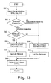
- FIG. 13 is a flow chart of the control executed in the ECU 13 of the direct fuel injection engine in accordance with the fourth embodiment of the present invention.
- Steps S61 to S63 in Figure 13 are the same as steps S1 to S3 of the first embodiment shown in Figure 5(a).
- the ECU 13 is configured to set the fuel stream penetration force to be relatively small in step S66.
- the fuel stream penetration force is set to be relatively small, a combustible first air-fuel mixture is formed in the combustion chamber 4 before the fuel stream collides against cavity 3a of the piston crown surface.
- step S67 the ECU 13 is configured to set the fuel pressure to be relatively low to achieve the relatively small fuel stream penetration force set in step S66.
- the ECU 13 is configured to set the fuel stream penetration force to be relatively large in step S64.
- the fuel stream penetration force is set to be relatively large, a combustible second air-fuel mixture after the fuel stream first collides against the cavity 3a of the piston crown surface.
- step S65 the ECU 13 is configured to set the fuel pressure to be relatively low to achieve the relatively large fuel stream penetration force set in step S64.
- step S68 the ECU 13 is configured to control the fuel stream penetration force by outputting a signal that drives the fuel injection pressure at a prescribed pressure in accordance with the fuel stream penetration force set for each regions as determined in the previous steps.
- the fuel stream penetration force is easily varied by changing the fuel pressure.
- the nozzle cross sectional area in order to reduce the penetration force of the fuel stream.
- the fuel stream penetration force is easily varied.
- the atomization of the fuel droplets can be improved when the nozzle cross sectional area is reduced.
- strengthening the swirl flow in the combustion chamber 4 can be also alternatively utilized in order to reduce the penetration force of the fuel stream. In such a case too, the fuel stream penetration force is easily varied. Moreover the mixing of the air-fuel mixture is further promoted when the swirl flow in the combustion chamber 4 is strengthened.
- the constitution of the direct fuel injection engine of the fifth embodiment is basically same as that of the fourth embodiment, except that the fuel injection valve 11 is a swirl type injection valve, and the fuel pump 9 is configured to control the fuel injection pressure to change the fuel injection angle of the fuel stream injected from the fuel injection valve 11.
- the fuel injection angle increases when the fuel injection pressure increases, and the fuel injection angle decreases when the fuel injection pressure decreases.
- the fuel injection pressure is increased to increase the fuel injection angle, and thus, a combustible first air-fuel mixture is formed, which is combusted before the fuel stream collides against the cavity 3a.
- the fuel injection pressure is reduced to decrease the fuel injection angle, and thus, a second air-fuel mixture is formed, which is combusted after the fuel stream collides against the cavity 3a and guided to the upper portion of the combustion chamber 4.
- Figure 14(a) is a diagrammatic chart illustrating another example of the relationship between the engine operating load and the fuel injection pressure in accordance with the fourth embodiment of the present invention.
- Figures 14(b)-14(e) are diagrammatic cross-sectional views of a combustion chamber illustrating distributions of the air-fuel mixture in the combustion chamber under various engine operating loads shown in Figure 14(a).
- the fuel injection pressure is preferably continuously varied in accordance with the engine operating load. More specifically, in the low-load stratified region A, the fuel injection pressure is set to be relatively large, and the fuel injection pressure is reduced as the load increases. Thus, the fuel injection angle in the low-load stratified combustion region A is relatively large, and the fuel injection angle decreases as the load increases. Accordingly, the first air-fuel mixture is formed during the low-load stratified combustion region A before the fuel stream collides against the cavity 3a.
- the fuel injection pressure is set to achieve a fuel injection angle with which the second combustible air-fuel mixture is formed as the fuel stream first collides against the peripheral surface of the cavity 3a and guided toward a center axis of the cavity 3a, as shown in Figure 14(c).
- the fuel stream that is guided from the cavity peripheral wall surface toward the center axis of the piston 3 continues to be oriented in the vicinity of the plug gap of the spark plug 12 to form a relatively small stratified air-fuel mixture. Accordingly, more stable combustion is accomplished when the load is relatively low in the high-load stratified combustion region B.
- the fuel injection pressure is set to achieve a fuel injection angle with which the second air-fuel mixture is formed as the fuel stream first collides against the bottom surface of the cavity 3a in the vicinity of the cavity center axis and guided toward the direction of the peripheral surface of the cavity 3a, as shown in Figure 14(d).
- the fuel stream that is guided from the vicinity of the center axis of the piston toward the direction of the peripheral wall surface of the cavity 3a continues to be oriented toward the vicinity of a plug gap of the spark plug 12 to form a relatively large stratified air-fuel mixture mass. Accordingly, a stable combustion can be accomplished in when the load is relatively high in the high-stratified combustion region B.
- the fifth embodiment of the present invention utilizes a swirl type injection valve as the fuel injection valve 11, and the fuel injection angle can be varied without complicating the structure of the fuel injection valve 11 by varying the fuel pressure (fuel injection pressure).
- the combustion chamber 4 can be arranged to have an alternate shape as shown in Figure 15(a). More specifically, the alternate shape of the combustion chamber 4 has a conically shaped guide wall (counterbore) around the perimeter of the injection valve 11 or the nozzle thereof, as shown in Figure 15(a).
- the guide wall (counterbore) is shaped so that the fuel stream exhibits almost no Coanda effect when the fuel injection angle is small (low fuel pressure, low fuel ratio, high back pressure), and exhibits a large Coanda effect when the fuel stream angle is large (high fuel pressure, high fuel ratio, low back pressure).
- the fuel injection angle can more easily be modified by effectively utilizing the Coanda effect by forming the approximately conically shaped counterbore around the perimeter of the fuel injection valve 11.
- the direct fuel injection engine of the present invention can more effectively vary the fuel injection angle by providing the guide wall (counterbore) in comparison with the shape of the combustion chamber 4 without a guide wall shown in Figure 15(b), in addition to controlling the fuel injection angle by controlling the fuel pressure, the fuel-air mass ratio, or the back pressure.
- the guide wall (counterbore) is approximately conically shaped, the Coanda effect can by utilized around the entire perimeter of the fuel stream, enabling more effective varying of the fuel injection angle.
Abstract
Description
- The present invention generally relates to a spark ignition internal combustion engine with direct fuel injection. More specifically, the present invention relates to a spark ignition internal combustion engine with direct fuel injection that achieves an improved combustibility of the fuel during stratified combustion.
- A spark ignition internal combustion engine with direct fuel injection is configured and arranged to perform a highly lean combustion by directly injecting a fuel into a cylinder from a fuel injection valve and forming a stratified air-fuel mixture in the cylinder during spark ignition combustion. Thus, with the direct fuel injection engine, the fuel consumption can be significantly reduced, particularly when the engine is operating under low and medium loads.
- In order to steadily ignite and combust the air-fuel mixture in the direct fuel injection engine, it is critical to reliably form an air-fuel mixture mass in a stratified state in the cylinder, which has an appropriate size and appropriate air-fuel ratio according to the speed and load of the engine.
- An appropriate stratified air-fuel mixture can be formed in the cylinder by providing a bowl-shaped cavity on a piston, setting a fuel stream injected from the fuel injection valve to collide against a wall surface of the bowl-shaped cavity, and forming a fuel stream circulation along the wall surface of the bowl-shaped cavity. For example, Japanese Laid-Open Patent Publication No. 11-82028 discloses a direct fuel injection spark ignition internal combustion engine that forms an appropriate stratified air-fuel mixture in a cylinder by disposing the fuel injection valve in the vicinity directly above the cavity, setting the fuel stream to collide against the cavity perimeter wall surface, and thereby forming a fuel stream circulation toward the center part of the cavity.
- In view of the above, it will be apparent to those skilled in the art from this disclosure that there exists a need for an improved spark ignition internal combustion engine with direct fuel injection. This invention addresses this need in the art as well as other needs, which will become apparent to those skilled in the art from this disclosure.
- With a spark ignition internal combustion engine with direct fuel injection, it is important to control the size of the air-fuel mixture mass in order to maintain the air-fuel ratio of the air-fuel mixture mass at the so-called ideal or stoichiometric air-fuel ratio under various load conditions of the engine. However, in the case of using the above mentioned conventional direct fuel injection spark ignition internal combustion engine that principally utilizes a cavity to form a stratified air-fuel mixture, it is difficult to vary the cavity volume in accordance with the various loads. Therefore, with the conventional direct fuel injection spark ignition internal combustion engine, the air-fuel ratio of the air-fuel mixture mass becomes too lean when the engine is operating in a low-load condition and too rich when the engine is operating in a high-load condition.
- The present invention considers the abovementioned problems, and has the object to enable forming of an air-fuel mixture mass of an appropriate air-fuel ratio and size according to the operating conditions of the engine in a combustion chamber having a fixed-volume cavity.
- Accordingly, in order to achieve the above object, a direct fuel injection engine is provided that basically comprises a combustion chamber, a spark plug, a fuel injection valve, a piston and a controller. The spark plug is positioned in an upper surface of the combustion chamber. The fuel injection valve is positioned in a substantially center portion of the upper surface of the combustion chamber, the fuel injection valve being configured and arranged to directly inject a fuel stream inside the combustion chamber. The piston has a guide wall surface being configured and arranged to guide the fuel stream injected from the fuel injection valve. The controller is configured and arranged to control operations of the spark plug and the fuel injection valve. The controller is further configured and arranged to ignite a first air-fuel mixture formed directly after the fuel stream is injected from the fuel injection valve and prior to a majority of the fuel stream being guide by the guide wall surface of the piston when the direct fuel injection engine is operating in a low-load stratified combustion region. The controller is further configured and arranged to ignite a second air-fuel mixture formed after a majority of the fuel stream is guided to an upper portion of the combustion chamber by the guide wall surface of the piston when the direct fuel injection engine is operating in a high-load stratified combustion region.
- These and other objects, features, aspects and advantages of the present invention will become apparent to those skilled in the art from the following detailed description, which, taken in conjunction with the annexed drawings, discloses a preferred embodiment of the present invention.
- Referring now to the attached drawings which form a part of this original disclosure:
- Figure 1 is a partial cross-sectional view of an injection portion of a direct fuel injection spark ignition internal combustion engine in accordance with a first embodiment of the present invention;
- Figure 2 is a partial cross-sectional view of one example of a fuel injection valve with a controllable fuel injection angle in accordance with the first embodiment of the present invention;
- Figure 3 is a partial cross-sectional view of another example of a fuel injection valve with a controllable fuel injection angle in accordance with the first embodiment of the present invention;
- Figure 4(a) is a diagrammatic chart illustrating the relationship between the engine operating load and the fuel stream angle in accordance with the first embodiment of the present invention;
- Figure 4(b) is a diagrammatic cross-sectional view of a combustion chamber illustrating distribution of the air-fuel mixture in the combustion chamber under a low-load stratified combustion region shown as "A" in Figure 4(a);
- Figure 4(c) is a diagrammatic cross-sectional view of a combustion chamber illustrating distribution of the air-fuel mixture in the combustion chamber under a high-load stratified combustion region shown as "B" in Figure 4(a);
- Figure 4(d) is a diagrammatic cross-sectional view of a combustion chamber illustrating distributions of the air-fuel mixture in the combustion chamber under a homogeneous combustion region shown as "C" in Figure 4(a);
- Figure 5(a) is a flow chart of the control executed in a controller of the direct fuel injection engine in accordance with the first embodiment of the present invention;
- Figure 5(b) is a flow chart of an alternate control executed in the controller of the direct fuel injection engine in accordance with the first embodiment of the present invention;
- Figure 6 is a partial cross-sectional view of an injection portion of a direct fuel injection spark ignition internal combustion engine in accordance with a second embodiment of the present invention;
- Figure 7(a) is a diagrammatic chart illustrating the relationship between the engine operating load and the injected fuel mass ratio to the air in accordance with the second embodiment of the present invention;
- Figure 7(b) is a diagrammatic cross-sectional view of a combustion chamber illustrating distribution of the air-fuel mixture in the combustion chamber under a low-load stratified combustion region shown as "A" in Figure 7(a);
- Figure 7(c) is a diagrammatic cross-sectional view of a combustion chamber illustrating distribution of the air-fuel mixture in the combustion chamber under a high-load stratified combustion region shown as "B" in Figure 7(a);
- Figure 7(d) is a diagrammatic cross-sectional view of a combustion chamber illustrating distributions of the air-fuel mixture in the combustion chamber under a homogeneous combustion region shown as "C" in Figure 7(a);
- Figure 8 is a flow chart of the control executed in a controller of the direct fuel injection engine in accordance with the second embodiment of the present invention;
- Figure 9(a) is a diagrammatic chart illustrating one example of the relationship between the engine operating load and the intake valve close timing in accordance with a third embodiment of the present invention;
- Figure 9(b) is a diagrammatic cross-sectional view of a combustion chamber illustrating distribution of the air-fuel mixture in the combustion chamber under a low-load stratified combustion region shown as "A" in Figure 9(a);
- Figure 9(c) is a diagrammatic cross-sectional view of a combustion chamber illustrating distribution of the air-fuel mixture in the combustion chamber under a high-load stratified combustion region shown as "B1" in Figure 9(a);
- Figure 9(d) is a diagrammatic cross-sectional view of a combustion chamber illustrating distribution of the air-fuel mixture in the combustion chamber under a high-load stratified combustion region shown as "B2" in Figure 9(a);
- Figure 9(e) is a diagrammatic cross-sectional view of a combustion chamber illustrating distributions of the air-fuel mixture in the combustion chamber under a homogeneous combustion region shown as "C" in Figure 9(a);
- Figure 10(a) is a diagrammatic chart illustrating another example of the relationship between the engine operating load and the intake valve close timing in accordance with the third embodiment of the present invention;
- Figure 10(b) is a diagrammatic cross-sectional view of a combustion chamber illustrating distribution of the air-fuel mixture in the combustion chamber under a low-load stratified combustion region shown as "A" in Figure 10(a);
- Figure 10(c) is a diagrammatic cross-sectional view of a combustion chamber illustrating distribution of the air-fuel mixture in the combustion chamber under a high-load stratified combustion region shown as "B" in Figure 10(a);
- Figure 10(d) is a diagrammatic cross-sectional view of a combustion chamber illustrating distributions of the air-fuel mixture in the combustion chamber under a homogeneous combustion region shown as "C" in Figure 10(a);
- Figure 11 is a flow chart of the control executed in a controller of the direct fuel injection engine in accordance with the third embodiment of the present invention;
- Figure 12(a) is a diagrammatic chart illustrating one example of the relationship between the engine operating load and the fuel pressure in accordance with a fourth embodiment of the present invention;
- Figure 12(b) is a diagrammatic cross-sectional view of a combustion chamber illustrating distribution of the air-fuel mixture in the combustion chamber under a low-load stratified combustion region shown as "A" in Figure 12(a);
- Figure 12(c) is a diagrammatic cross-sectional view of a combustion chamber illustrating distribution of the air-fuel mixture in the combustion chamber under a high-load stratified combustion region shown as "B" in Figure 12(a);
- Figure 12(d) is a diagrammatic cross-sectional view of a combustion chamber illustrating distributions of the air-fuel mixture in the combustion chamber under a homogeneous combustion region shown as "C" in Figure 12(a);
- Figure 13 is a flow chart of the control executed in a controller of the direct fuel injection engine in accordance with the fourth embodiment of the present invention;
- Figure 14(a) is a diagrammatic chart illustrating another example of the relationship between the engine operating load and the fuel injection pressure in accordance with the fifth embodiment of the present invention;
- Figure 14(b) is a diagrammatic cross-sectional view of a combustion chamber illustrating distribution of the air-fuel mixture in the combustion chamber under a low-load stratified combustion region shown as "A" in Figure 14(a);
- Figure 14(c) is a diagrammatic cross-sectional view of a combustion chamber illustrating distribution of the air-fuel mixture in the combustion chamber under a high-load stratified combustion region shown as "B1' " in Figure 14(a);
- Figure 14(d) is a diagrammatic cross-sectional view of a combustion chamber illustrating distributions of the air-fuel mixture in the combustion chamber under a homogeneous combustion region shown as "B2' " in Figure 14(a);
- Figure 14(e) is a diagrammatic cross-sectional view of a combustion chamber illustrating distributions of the air-fuel mixture in the combustion chamber under a homogeneous combustion region shown as "C" in Figure 14(a);
- Figure 15(a) is a diagrammatic view of the combustion chamber illustrating an air-fuel mixture distribution with a counterbore in the vicinity of the fuel injection valve; and
- Figure 15(a) and 15(b) is a diagrammatic view of the combustion chamber illustrating an air-fuel mixture distribution without a counterbore in the vicinity of the fuel injection valve.
- Selected embodiments of the present invention will now be explained with reference to the drawings. It will be apparent to those skilled in the art from this disclosure that the following descriptions of the embodiments of the present invention are provided for illustration only and not for the purpose of limiting the invention as defined by the appended claims and their equivalents.
- Referring initially to Figure 1, a spark ignition internal combustion engine with direct fuel injection (herein after referred to as "direct fuel injection engine") is illustrated in accordance with a first embodiment of the present invention. Figure 1 is a partial cross-sectional view of an injection portion of the direct fuel injection engine of the first embodiment. As seen in Figure 1, the injection portion of the direct fuel injection engine includes a
cylinder head 1, acylinder block 2, apiston 3, at least oneintake valve 5, at least one exhaust valve 6, at least oneintake port 7, at least oneexhaust port 8, afuel injection valve 11 and aspark plug 12. Acombustion chamber 4 is basically defined by thecylinder head 1, thecylinder block 2 and thepiston 3. New air is introduced into thecombustion chamber 4 from theintake port 7 via theintake valve 5, while exhaust gas is exhausted from theexhaust port 8 via the exhaust valve 6. A fuel pump 9 is disposed at the end of the camshaft which drives theintake valve 5. Of course, it will be apparent to those skilled in the art from this disclosure that the fuel pump 9 can be arranged to be driven by a separately arranged electric motor. Moreover, a variablyvalve timing mechanism 5a is preferably used to control a valve timing of the intake cam. Variably valve timing mechanism are well known in the art, and thus, the variablyvalve timing mechanism 5a will not be discussed or illustrated in detail herein. - As seen in Figure 1, the
fuel injection valve 11 is positioned in a substantially center portion of an upper surface of thecombustion chamber 4. In other words, thefuel injection valve 11 is preferably centered or substantially centered on the center longitudinal axis of thepiston 3. Thefuel injection valve 11 is configured and arranged to inject the fuel pressurized by the fuel pump 9 and conveyed via afuel conduit 10 into thecombustion chamber 4. Thefuel injection valve 11 is preferably configured and arranged such that the fuel stream injected from thefuel injection valve 11 spreads in a substantially conical shape in thecombustion chamber 4. Moreover, in the first embodiment of the present invention, thefuel injection valve 11 is configured and arranged to inject a fuel stream in at least two different fuel injection angles, i.e., angles of an apex of the conical-shaped fuel stream, by changing a lift of a needle valve of thefuel injection valve 11. - One example of the
fuel injection valve 11 utilizing a needle valve is disclosed in Japanese Laid Open Patent Publication No. H8-177684. As shown in Figure 2, thefuel injection valve 11 includes aneedle valve 11A and avalve body 11B in which theneedle valve 11A is inserted. Thevalve body 11B also includes anozzle hole 11C. Afuel passageway 11a is formed in thevalve body 11B. The downstream end of thefuel passageway 11a is branched into a lower sidewide angle spout 11b and anarrow angle spout 11c. Thewide angle spout 11b is arranged to be perpendicular to the axial direction of theneedle valve 11A. Thenarrow angle spout 11c is inclined downwardly toward thenozzle hole 11C. With thefuel injection valve 11 shown in Figure 2, when a lift of theneedle valve 11A is small, only thewide angle spout 11b opens. Thus, the fuel spouted from thewide angle spout 11b forms a strong swirl in a space inside thevalve body 11B wherein theneedle valve 11A moves, and is injected in a substantially conical shape from thenozzle hole 11C into thecombustion chamber 4. On the other hand, when the lift of theneedle valve 11 A is large, thewide angle spout 11b and thenarrow angle spout 11c both open. Thus, the swirl of the fuel spouted from thewide angle spout 11b is weakened by the force of the fuel flow spouted from the downwardly inclinednarrow angle spout 11c toward thenozzle hole 11C. Thus, when the lift of theneedle valve 11A is large, the fuel injection angle of the fuel stream injected from thefuel injection valve 11 is smaller than the fuel injection angle of the fuel stream injected from thefuel injection valve 11 when the lift of theneedle valve 11A is small. Accordingly, the injection angle of the conically spreading fuel stream from thenozzle hole 11C increases comparatively when the lift of theneedle valve 11A is small, opening only thewide angle spout 11b, and decreases comparatively when the lift of theneedle valve 11A is large, opening both thewide angle spout 11b and thenarrow angle spout 11c. - Alternatively, a fuel injection valve 11' can be substituted with the
fuel injection valve 11 in the direct fuel injection engine of the first embodiment. More specifically, the fuel injection valve 11' is configured and arranged as disclosed in Japanese Laid Open Patent Publication No. 2000-303936. As shown in Figure 3, the fuel injection valve 11' basically comprises aneedle valve 11D and avalve body 11E. A T-shapedfuel passageway 11d is formed in theneedle valve 11D. An uppernarrow angle nozzle 11e and a lowerwide angle nozzle 11f are formed in avalve body 11E. The uppernarrow angle nozzle 11e has a large downwardly angled injection angle, and the lowerwide angle nozzle 11f has a small downwardly angled injection angle. When the lift of theneedle valve 11D is small, only thewide angle nozzle 11f opens. Thus, the fuel is injected from thewide angle nozzle 11f at a small downwardly angled injection angle into thecombustion chamber 4. When the lift of theneedle valve 11D is large, both thewide angle nozzle 11f and thenarrow angle nozzle 11e open. Thus, the fuel is urged with a downwardly directed injection force by the fuel injected from thenarrow angle nozzle 11e, and thus, the fuel injection angle from the fuel injection valve 11' is relatively small. Accordingly, with the fuel injection valve 11', the injection angle is comparatively large when the lift of theneedle valve 11D is small, opening only thewide angle nozzle 11f, and is relatively small when the lift of theneedle valve 11D is large, opening both thewide angle nozzle 11f and thenarrow angle nozzle 11e. - Of course, it will be apparent to those skilled in the art from this disclosure that a construction of the
fuel injection valve 11 is not limited to the above mentioned examples. Rather, any construction of thefuel injection valve 11 can be utilized provided that thefuel injection valve 11 is adopted to carry out the same functions in the present invention. More specifically, in the first embodiment of the present invention, any construction of thefuel injection valve 11 can be utilized as long as thefuel injection valve 11 is arranged to inject the fuel into thecombustion chamber 4 in at least two different fuel injection angles. - As shown in Figure 1, the
piston 3 of the direct fuel injection engine includes a bowl-shapedcavity 3a on the piston crown surface which is a position opposite thefuel injection valve 11. When the direct fuel injection engine is operating in a high-load stratified combustion region, the fuel injected from thefuel injection valve 11 principally forms a stratified air-fuel mixture mass within thecavity 3a and in the upper space of thecavity 3a. Thecavity 3a is defined by a guide wall surface comprising a bottom surface and a peripheral wall surface that curves upwardly from the bottom surface of thecavity 3a and is angled inwardly towards the center axis of thepiston 3 at its upper end section. Thus, the bottom surface and the peripheral wall surface of thecavity 3a are shaped so that the fuel stream collided against thecavity 3a is oriented toward the substantially upper center part of thecombustion chamber 4, which includes thespark plug 12. Specifically, the shape of the peripheral wall surface of thecavity 3a is curved generally toward thefuel injection valve 11, and formed so that the edge peripheral wall surface is oriented at an angle formed between the cylinder axis and the approximate direction in which the fuel stream is injected from thefuel injection valve 11. Therefore, the fuel stream collided against thecavity 3a wall spreads outwardly beyond the outer edge of the initial fuel stream from thefuel injection valve 11 to the outside of thecavity 3a, but the spread can be accumulated on the approximately inner side of the space above thecavity 3a, and it is possible to form the stratified combustible air-fuel mixture because excessive diffusion of the air-fuel mixture is suppressed. - Then, the
spark plug 12 is configured and arranged to ignite and combust the air-fuel mixture. As seen in Figure 1, thespark plug 12 is positioned in the upper surface of thecombustion chamber 4 and is located adjacent thefuel injection valve 11. - The direct fuel injection engine of the present invention is controlled in an integrated manner by a controller or engine control unit (ECU) 13. Moreover, the direct fuel injection engine of the present invention includes various sensors that monitor an operating condition of the vehicle, such as a crank angle sensor, a cooling water temperature sensor and a throttle opening sensor. More specifically, a crank angle sensor signal, a cooling water temperature signal, and a throttle opening signal are input to the
ECU 13, and theECU 13 is configured to perform the above mentioned various control functions, such as control of theneedle valve 11A of thefuel injection valve 11 and control of thespark plug 12, based the above mentioned input signals. - The
ECU 13 preferably includes a microcomputer with a control program that controls the direct fuel injection engine as discussed below. TheECU 13 can also include other conventional components such as an input interface circuit, an output interface circuit, and storage devices such as a ROM (Read Only Memory) device and a RAM (Random Access Memory) device. The microcomputer of theECU 13 is programmed to control the direct fuel injection engine. The memory circuit stores processing results and control programs that are run by the processor circuit. TheECU 13 is operatively coupled to the various components of the direct fuel injection engine in a conventional manner. The internal RAM of theECU 13 stores statuses of operational flags and various control data. TheECU 13 is capable of selectively controlling any of the components of the control system in accordance with the control program. It will be apparent to those skilled in the art from this disclosure that the precise structure and algorithms for theECU 13 can be any combination of hardware and software that will carry out the functions of the present invention. In other words, "means plus function" clauses as utilized in the specification and claims should include any structure or hardware and/or algorithm or software that can be utilized to carry out the function of the "means plus function" clause. - The direct fuel injection engine of the present invention is configured and arranged to perform combustion of the air-fuel mixture in a stratified combustion mode or a homogeneous combustion mode depending on an operating condition of the direct fuel injection engine. In the stratified combustion mode, a relatively small amount of fuel is injected during a compression stroke (particularly in the latter half of the compression stroke) to form a stratified fuel-air mixture mass to improve fuel economy through lean operation. Since the stratified fuel-air mixture is formed with the surrounding area in the
combustion chamber 4 being occupied by air, stable combustion is accomplished even with the relatively small amount of fuel. On the other hand, in the homogeneous combustion mode, the fuel is injected during an intake stroke (particularly in the former half of the intake stroke) to perform a stoichiometric operation (stoichiometric air-fuel ratio operation). Thus, a homogeneous fuel-air mixture is formed throughout thecombustion chamber 4. Since the air and the fuel are mixed thoroughly before the combustion occurs, high power output can be obtained in the homogeneous combustion. - Figure 4(a) is a diagrammatic chart showing the relationship between the operating condition (load) and the fuel injection angle of the fuel stream injected from the
fuel injection valve 11. Figures 4(b)-4(d) show the distribution of the air-fuel mixture in thecombustion chamber 4 under various operating loads with the reference to the loads shown in Figure 4(a). - The operating load is generally divided into a low-load stratified combustion region shown as "A" in Figure 4(a), a high-load stratified combustion region shown as "B" in Figure 4(a), and a homogeneous combustion region shown as "C" in Figure 4(a). Generally, the amount of fuel injected during the low-load stratified combustion region A is small. If the fuel injection angle is set to be relatively small so that the injected fuel stream collides against the wall surface of the
cavity 3a, the fuel stream will be highly diffused in thecavity 3a and above thecavity 3a. However, since the amount of fuel injected in the low-load stratified combustion region A is small, a lean air-fuel mixture will be formed having poor ignitability and combustion stability if the fuel stream is diffused after the fuel stream collides against thecavity 3a. Thus, in the first embodiment of the present invention, thefuel injection valve 11 is configured and arranged to set the fuel injection angle such that a combustible air-fuel mixture is formed in thecombustion chamber 4 before the fuel stream collides against thecavity 3a in the low-load stratified combustion region A. More specifically, thefuel injection valve 11 is configured and arranged to set the injection angle of the fuel stream to be relatively large in the low-load stratified combustion region A as seen in Figure 4(a). Accordingly, a first air-fuel mixture that is close to stoichiometric state is formed in the upper center portion of thecombustion chamber 4 where thespark plug 12 is located before the fuel stream collides against the wall surface of thecavity 3a, as shown in Figure 4(b). As used herein, the first air-fuel mixture is a combustible air-fuel mixture that is close to the stoichiometric state formed in thecombustion chamber 4 relatively immediately after the fuel stream is injected from thefuel injection valve 11. The first air-fuel mixture has a superior ignitability and combustion stability in the low-load stratified combustion region A. _In other words, in the first embodiment of the present invention, the fuel stream injected from thefuel injection valve 11 is arranged to directly reach a plug gap of thespark plug 12 and form the first air-fuel mixture in the upper portion of thecombustion chamber 4 in the low-load stratified combustion region A. Thus, thespark plug 12 is configured and arranged to ignite the first air-fuel mixture relatively immediately after the fuel is injected from thefuel injection valve 11 when the direct fuel injection engine is operating in the low-load stratified combustion region A. - On the other hand, the amount of the fuel injected from the
fuel injection valve 11 in the high-load stratified combustion region B is larger than the amount of fuel injected in the low-load stratified combustion region A. Under such condition, if the fuel stream is oriented directly toward the vicinity of a plug gap of thespark plug 12, an excessively rich air-fuel mixture is formed in the upper part of the combustion chamber, and wet fouling or dry fouling of thespark plug 12 will occur. Thus, as seen in Figure 4(a), the fuel injection angle is set relatively small under the high-load stratified combustion region B. Accordingly, the fuel stream collides against the wall surface of thecavity 3a, and becomes highly diffused in thecavity 3a and the upper space of thecavity 3a, as seen in Figure 4(c). Therefore, a second air-fuel mixture that is close to a stoichiometric state can be formed after the fuel stream collides against thecavity 3a in the high-load stratified combustion region B. As used herein the second air-fuel mixture is a combustible air-fuel mixture close to the stoichiometric state formed after the fuel stream injected from thefuel injection valve 11 collides against thecavity 3a and is guided toward the upper portion of thecombustion chamber 4. Thus, the second air-fuel mixture is formed within thecavity 3a and thereabove where thespark plug 12 is located and_has a superior ignitability and combustion stability. In other words, in the first embodiment of the present invention, the fuel stream injected from thefuel injection valve 11 is arranged to reach thespark plug 12 and form the second air-fuel mixture after the fuel stream collides against thecavity 3a and is guided toward the upper portion of thecombustion chamber 4. Accordingly, thespark plug 12 is configured and arranged to ignite the second air-fuel mixture after the fuel stream collides the wall surface of thecavity 3a and the fuel stream is guided to the upper portion of thecombustion chamber 4 by the wall surface of thecavity 3a when the internal combustion engine is operating in a high-load stratified combustion region B. Since the fuel stream is not directly oriented toward thespark plug 12 after the fuel stream is injected from thefuel injection valve 11, the wet fouling or dry fouling of thespark plug 12 is prevented. - In the homogeneous combustion region C, a homogeneous air-fuel mixture fills the
combustion chamber 4, as seen in Figure 4(d). In the first embodiment of the present invention, the fuel injection angle in the homogeneous combustion mode is preferably set to a relatively large angle as shown in Figure 4(a). However, it is apparent to those skilled in the art from this disclosure that the fuel injection angle in the homogeneous combustion region C is not limited to the angle shown in Figure 4(a). Rather, the fuel injection angle in the homogeneous combustion region C can be set to any angle as long as the air-fuel mixture that achieves the homogeneous combustion can be formed in thecombustion chamber 4 as shown in Figure 4(d) to carry out the present invention. - As described above, the fuel injection angle of the fuel stream injected from the
fuel injection valve 11 is controlled in accordance with the load of the direct fuel injection engine. When the load is relatively low, the diffusion of the fuel stream is suppressed and a comparatively small air-fuel mixture mass is formed by forming the combustible first air-fuel mixture before the fuel stream collides against the wall surface of thecavity 3a. On the other hand, when the load is relatively high, the diffusion and mixing of the fuel stream is promoted as the fuel stream hits the wall surface of thecavity 3a and is guided toward the upper space of thecavity 3a. Thus, the comparatively large second air-fuel mixture mass is formed from the interior to the exterior of thecavity 3a. Therefore, the fuel can be effectively combusted under a broad range of engine operation conditions. A control flow executed by theECU 13 is shown in Figure 5(a) in accordance with the first embodiment of the present invention. The direct fuel injection engine of the first embodiment is basically configured and arranged to control the fuel injection angle of the fuel stream, and the size of the air-fuel mixture mass in thecombustion chamber 4 such that thespark plug 12 ignites the first air-fuel mixture directly after the fuel is injected from thefuel injection valve 11 in the low-load stratified combustion region A, and thespark plug 12 ignites the second air-fuel mixture after the fuel stream is guided to the upper portion of the combustion chamber by thecavity 3a in the high-load stratified combustion region B. - In Step S1 in Figure 5(a), the
ECU 13 is configured to detect the rotational speed and load of the direct fuel injection engine based on input signals from the crank angle sensor, the throttle opening sensor, and the like. - In step S2, the
ECU 13 is configured to determine whether to perform stratified combustion mode or homogeneous combustion mode based on the operating condition of the direct fuel injection engine determined based on the signals obtained in step S1. The determination of the combustion mode is made based on a previously stored table containing entries derived by empirically examining the relationship between the rotational speed and load, and the combustion mode. If a determination was made in step S2 to perform the homogeneous combustion mode, then the procedure proceeds to step S6. - On the other hand, if a determination was made in step S2 to perform the stratified combustion mode, then the procedure proceeds to step S3. In step S3 the
ECU 13 is configured to determine whether the load of the direct fuel injection engine is greater than or equal to a prescribed load. More specifically, the prescribed load is a threshold value used to decide whether the internal combustion engine is operating in the low-load stratified combustion region A or the high-load stratified combustion region B. The prescribed load is preferably derived empirically and prestored in theECU 13. Thus, theECU 13 is configured to select, in accordance with the load of the direct fuel injection engine, whether to form a combustible first air-fuel mixture before the fuel stream collides against thecavity 3a on the piston crown surface, or to form a combustible second air-fuel mixture after the fuel stream collides against thecavity 3a on piston crown surface. In other words, as explained above, in the low-load stratified combustion region A (when the load is lower than the prescribed load), the combustible first air-fuel mixture is formed before the fuel stream collides against thecavity 3a. Thus, the fuel injection angle is set to be relatively large. In the high-load stratified combustion region B (when the load is higher than the prescribed load), a combustible air-fuel mixture is formed after the fuel stream collides against the piston crown surface. Thus, the injection angle is set to be relatively small. Accordingly, if the engine load is greater than or equal to the prescribed load in step S3, then the procedure proceeds to step S4. If the engine load is smaller than the prescribed load in step S3, then the procedure proceeds to step S6. - In step S4, the
ECU 13 is configured to select a relatively small fuel injection angle. The procedure then proceeds to step S5, where theECU 13 is configured to select a large lift of theneedle valve 11A to achieve the relatively small fuel injection angle. - On the other hand, in step S6, the
ECU 13 is configured to select a relatively large fuel injection angle. The procedure then proceeds to step S7, where theECU 13 is configured to select a small lift of theneedle valve 11A to achieve a relatively large fuel injection angle. - Next, in step S8, the
ECU 13 is configured to control the fuel injection angle by outputting a signal that drives theneedle valve 11A to lift by a predetermined amount in accordance with an injection parameter determined in steps S5 or S7. Of course it will be apparent to those skilled in the art from this disclosure that in step S8, theECU 13 can be configured to control other fuel injection parameters including, but not limited to, outputting a signal that drives to the fuel pump 9, which supplies a prescribed fuel pressure. - Alternatively, as seen in Figure 5(b), the control of the direct fuel injection engine of the present invention can be implemented by referencing tables containing the fuel injection timing, fuel injection quantity, and fuel injection angle, which are assigned beforehand for each operating condition. These tables are preferably empirically derived beforehand.
- More specifically, in step S1' in Figure 5(b), the
ECU 13 is configured to detect the rotational speed and load of the direct fuel injection engine based on signals from the crank angle sensor, throttle opening sensor, and the like. - Next, in step S2', the
ECU 13 is configured to read in the tables wherein the fuel injection timing, fuel injection quantity, and fuel injection angle based on engine operating conditions are prestored. Based on the values set in the tables, theECU 13 is configured to select, in accordance with the engine load, whether to directly orient the fuel stream toward the vicinity of the spark plug gap, or to form a combustible air-fuel mixture after first colliding against the piston crown surface. More specifically, theECU 13 is configured to increase the fuel injection angle when orienting the fuel stream directly toward the vicinity of the spark plug gap, and decrease the fuel injection angle when forming a combustible second air-fuel mixture after the fuel stream collides against thecavity 3a of the piston crown surface. - In step S3', in accordance with injection parameters decided in a previous step, the
ECU 13 is configured to control the fuel injection by at least outputting a signal that drives theneedle valve 11A of thefuel injection valve 11, and the fuel pump 9, which supplies a prescribed fuel pressure. - Accordingly, with the direct fuel injection engine of the first embodiment, a compact first air-fuel mixture mass can be formed in the low-load stratified combustion region A and a relatively large second air-fuel mixture mass can be formed in the high-load stratified combustion region B. Thus, the direct fuel injection engine of the present invention enables stable combustion over a wide load range. In addition, because the fuel stream does not collide against the
cavity 3a on the piston crown surface in the low-load stratified combustion region A, the unburned hydrocarbons and cooling losses can be reduced. Thus, the fuel consumption can be improved and the deleterious exhaust emissions can be reduced. - Referring now to Figures 6 and 7, a direct fuel injection spark ignition internal combustion engine in accordance with a second embodiment will now be explained. In view of the similarity between the first and second embodiments, the parts of the second embodiment that are identical to the parts of the first embodiment will be given the same reference numerals as the parts of the first embodiment. Moreover, the descriptions of the parts of the second embodiment that are identical to the parts of the first embodiment may be omitted for the sake of brevity.
- Figure 6 is a partial cross-sectional view of an injection portion of the direct fuel injection engine of the second embodiment. Basically, the direct fuel injection engine of the second embodiment is identical to the first embodiment shown in Figure 1, except that an
air pump 14 is provided at the end of the intake camshaft, and a dual-fluidfuel injection valve 11" is used as thefuel injection valve 11. The air pressurized by theair pump 14 is conveyed to the dual-fluidfuel injection valve 11" via anair conduit 15 and injected into thecombustion chamber 4 along with the fuel by the dual-fluidfuel injection valve 11". The dual-fluid fuel injection valve 11' is configured and arranged to inject the fuel and the air separately into thecombustion chamber 4 in a predetermined ratio by controlling the lift of a needle valve of the dual-fluidfuel injection valve 11". When the lift of the needle valve is small, the area of the opening of the air nozzle connected to theair pump 14 and facing the dual-fluid fuel injection valve 11' is small or substantially zero (in other words, closed). Thus, the ratio of the mass of the air to the mass of the fuel between the air and fuel injected into thecombustion chamber 4 is small. When the lift of the needle valve is large, the area of the opening of the air nozzle is large. Thus, the ratio of the mass of the air to the mass of the fuel increases. Accordingly, the fuel-air mass ratio between the fuel and air injected from the dual-fluidfuel injection valve 11" can be easily varied by varying the amount of air injected from the dual-fluidfuel injection valve 11". The dual-fluid fuel injection valves are conventional components that are well known in the art. Since the dual-fluid fuel injection valves are well known in the art, these structures will not be discussed or illustrated in detail herein. - Figure 7(a) is a diagrammatic chart illustrating the relationship between the engine operating load and the injected fuel-air mass ratio in accordance with the second embodiment of the present invention. Figures 7(b)-7(d) are diagrammatic cross-sectional views of the
combustion chamber 4 illustrating distributions of the air-fuel mixture in thecombustion chamber 4 under various engine operating regions shown in Figure 7(a). - As seen in Figure 7(a), the direct fuel injection engine is configured and arranged to increase the mass ratio of the fuel injected to the air when the direct fuel injection engine is operating in a low-load stratified combustion region A. By increasing the mass ratio of the fuel to the air, the fuel injection angle is increased. Thus, as seen in Figure 7(b), a first air-fuel mixture having superior ignitability and combustion stability can be formed in the upper center portion of the
combustion chamber 4 where thespark plug 12 is located before the fuel stream collides against thecavity 3a of the piston. - On the other hand, as seen in Figure 7(b), the direct fuel injection engine is configured and arranged to decrease the mass ratio of the fuel to the air injected into the
combustion chamber 4 when the direct fuel injection engine is operating in the high-load stratified combustion region B. When the mass ratio of the fuel to the air is decreased, the fuel injection angle becomes smaller. Thus, as seen in Figure 7(c), comparatively large second air-fuel mixture mass can be formed from the interior to the exterior of thecavity 3a after the fuel stream collides against the bottom surface of thecavity 3a and the diffusion and mixing of the fuel stream is promoted. As explained above, the fuel-air mass ratio between the fuel and air injected from the dual-fluidfuel injection valve 11" can be easily varied by varying the amount of air injected. - In the homogeneous combustion region C, a homogeneous air-fuel mixture fills the
combustion chamber 4, as seen in Figure 7(d). In the second embodiment of the present invention, the fuel mass ratio to the air in the homogeneous combustion mode is preferably set to a relatively large as shown in Figure 7(a) to achieve a relatively large fuel injection angle. However, it is apparent to those skilled in the art from this disclosure that the fuel mass ratio in the homogeneous combustion region C is not limited to the ratio shown in Figure 7(a). Rather, the fuel mass ratio in the homogeneous combustion region C can be set to any value as long as the air-fuel mixture that achieves the homogeneous combustion can be formed in the combustion chamber as shown in Figure 7(d) to carry out the present invention. - Figure 8 is a flow chart of the control executed in the
ECU 13 of the direct fuel injection engine in accordance with the second embodiment. Steps S21-S23 in Figure 8 are basically identical to steps S1-S3 in Figure 5(a) of the first embodiment. When it is determined in step S22 to perform a homogeneous combustion or when it is determined in step S23 that the load is smaller than the prescribed load (when the direct fuel injection engine is operating in a low-load stratified combustion region A), theECU 13 is configured to set the fuel injection angle to be a relatively large angle in step S26. Thus, in step S27, the lift of the needle valve of the dual-fluidfuel injection valve 11" is reduced to achieve the relatively large fuel injection angle by reducing the amount of air and increasing the mass ratio of the fuel injected from the dual-fluidfuel injection valve 11". When it is determined in step S24 that the load is greater than the prescribed load (when the direct fuel injection engine is operating in a high-load stratified combustion region B), theECU 13 is configured to set the fuel injection angle to be a relatively small angle in step S24. Thus, in step S25, the lift of the needle valve of the dual-fluidfuel injection valve 11" is increased to achieve a small fuel injection angle by increasing the amount of air and decreasing the fuel mass ratio of the fuel injected from the dual-fluidfuel injection valve 11". - Accordingly, in the second embodiment of the present invention, the dual-fluid
fuel injection valve 11" is used as a fuel injection valve, and the injected liquid-air mass ratio (the mass ratio of fuel) is increased or decreased to control the fuel injection angle. Thus, the fuel injection angle can be varied merely by controlling the dual-fluidfuel injection valve 11" without increasing the complexity of the injection valve structure. - Referring now to Figures 9-11, a direct fuel injection spark ignition internal combustion engine in accordance with a third embodiment will now be explained. In view of the similarity between the first and third embodiments, the parts of the third embodiment that are identical to the parts of the first embodiment will be given the same reference numerals as the parts of the first embodiment. Moreover, the descriptions of the parts of the third embodiment that are identical to the parts of the first embodiment may be omitted for the sake of brevity.
- The direct fuel injection engine of the third embodiment is basically the same as the direct fuel injection engine of the first embodiment, except that the fuel injection angle is varied by controlling a back pressure (pressure inside the combustion chamber 4) at the time when the fuel stream is injected by variably controlling a valve timing of the intake cam, e.g., using the variable
valve timing mechanism 5a that is diaramatically shown in Figure 1. The valve timing of the intake cam can be variably controlled by the variablevalve timing mechanism 5a, for example, by varying the phase of the cam or switching between a plurality of cams. Of course, it is apparent to those skilled in the art from this disclosure that the configuration of how to variably control the valve timing of the intake cam is not limited to the above mentioned configurations. Rather, any configuration in which the timing of the valve can be arbitrarily varied can be used in order to carry out the third embodiment of the present invention. Moreover, in the third embodiment of the present invention, any type of fuel injection valves, such as a swirl-type injection valve or a dual-fluid fuel injection valve, can be used as thefuel injection valve 11 provided the fuel injection angle of the fuel stream injected from theinjection valve 11 increases as the back pressure (pressure inside the combustion chamber 4) decreases. - Figure 9(a) is a diagrammatic chart illustrating the relationship between the engine operating load and the closing timing of the
intake valve 5 in accordance with the third embodiment of the present invention. Figures 9(b)-9(e) are diagrammatic cross-sectional views of thecombustion chamber 4 illustrating distributions of the air-fuel mixture in thecombustion chamber 4 under various engine operating regions shown in Figure 9(a). - As shown in Figure 9(a), the closing timing of the
intake valve 5 is set to be more retarded when the direct fuel injection engine is operating in the low-load stratified combustion region A. When the closing timing of theintake valve 5 is retarded, the back pressure (pressure inside the combustion chamber 4) is reduced during the compression stroke in which the fuel is injected. Thus, the fuel injection angle increases to a relatively large angle and a combustible air-fuel mixture is formed before the fuel stream collides against thecavity 3a of the piston crown surface. Accordingly, a first air-fuel mixture can be formed having superior ignitability and combustion stability as shown in Figure 9(b) by retarding the close timing of theintake valve 5 in the low-load stratified combustion region A. - As shown in Figure 9(b), the closing timing of the
intake valve 5 is set to be more advanced in the high-load stratified combustion region B than in the low-load stratified combustion region A. When the closing timing of theintake valve 5 is advanced, the back pressure (pressure inside the combustion chamber 4) is increased. Thus, the fuel injection angle decreases to a relatively small angle such that the fuel stream collides thecavity 3a of the piston crown surface and the diffusion and mixing of the fuel stream is promoted. Accordingly, a comparatively large second air-fuel mixture mass can be formed from the interior to the exterior of thecavity 3a as shown in Figures 9(c) and 9(d). - Moreover, in the third embodiment of the present invention, when the load is relatively low in the high-load stratified combustion region B (shown as "B1" in Figure 9(a)), the closing timing of the
intake valve 5 is set to be relatively more delayed so that the fuel injection angle is set to be relatively large. In such a case, the second combustible air-fuel mixture is formed as the fuel stream first collides against the peripheral surface of thecavity 3a and guided toward a center axis of thecavity 3a, as shown in Figure 9(c). Thus, the fuel stream that is guided from the cavity peripheral wall surface toward the center axis continues to be oriented in the vicinity of the plug gap of thespark plug 12 to form a relatively small stratified air-fuel mixture. Accordingly, more stable combustion is accomplished when the load is relatively low in the high-load stratified combustion region B. - Furthermore, when the load is relatively large in the high-load stratified combustion region B (shown as "B2" in Figure 9(a)), the closing timing of the
intake valve 5 is set to be relatively more advanced so that the fuel injection angle is set to be relatively small. In such a case, the second air-fuel mixture is formed as the fuel stream first collides against the bottom surface of thecavity 3a in the vicinity of the cavity center axis and guided toward the direction of the peripheral surface of thecavity 3a, as shown in Figure 9(d). Thus, the fuel stream that is guided from the vicinity of the center axis toward the direction of the peripheral wall surface continues to be oriented toward the vicinity of the plug gap of thespark plug 12 to form a relatively large stratified air-fuel mixture mass. Accordingly, a stable combustion can be accomplished in when the load is relatively high in the high-stratified combustion region B. - In the homogeneous combustion region C, a homogeneous air-fuel mixture fills the
combustion chamber 4, as seen in Figure 9(e). Since a large amount of air is needed in the homogeneous combustion mode in the vicinity of full throttle load, the close timing of theintake valve 5 is preferably advanced more than in the high-load stratified combustion region B. - Alternatively, the close timing of the
intake valve 5 in the high-load stratified region B can be set as a single value as shown in Figure 10(a). In such a case, the close timing of theintake valve 5 is set to be relatively advanced so that the fuel injection angle is set to be relatively small. In such a case, the second air-fuel mixture is formed as the fuel stream first collides against the bottom surface of thecavity 3a in the vicinity of the cavity center axis and guided toward the direction of the peripheral surface of thecavity 3a, as shown in Figure 10(c). Thus, the fuel stream that is guided from the vicinity of the center axis toward the direction of the peripheral wall surface continues to be oriented toward the vicinity of the plug gap of thespark plug 12 to form a relatively large stratified air-fuel mixture mass. - Figure 11 is a flow chart of the control executed in the
ECU 13 of the direct fuel injection engine in accordance with the third embodiment. - In step S31, the
ECU 13 is configured to detect the rotational speed and load of the direct fuel injection engine. In step S32, theECU 13 is configured to determine whether to perform stratified combustion or homogeneous combustion based on the operating conditions of the direct fuel injection engine obtained in step S31. When theECU 13 determines to perform the homogeneous combustion in step S32, then the procedure proceeds to step S34. In step S34, theECU 13 is configured to determine whether the engine load is greater than or equal to a prescribed load TB2. Since homogeneous combustion is being preformed, the engine is operating under a high load condition that is greater than the prescribed load TB2. Thus, when homogeneous combustion is being preformed, it is determined in step S34 that the load is greater than or equal to TB2, and then the fuel injection angle is set to a minimum angle in step S35, and the procedure proceeds to step S36. In step S36, theECU 13 is configured to maximally advance the close timing of theintake valve 5 to minimize the back pressure (pressure inside the combustion chamber 4) during the fuel injection so that the fuel injection angle is controlled to the minimum angle 1. More preferably, the close timing of theintake valve 5 is preferably advanced more than in the high-load stratified combustion region B because the load in the homogeneous combustion is higher than in the stratified combustion and a greater amount of air is required. - When the
ECU 13 determines to perform the stratified combustion in step S32, the procedure proceeds to step S33. In step S33, theECU 13 is configured to determine whether the load is greater than or equal to a prescribed load TB1. When the load is greater than or equal to TB1, it is determined that the direct fuel injection engine is operating in the high-load stratified combustion region B. Thus, the combustible second air-fuel mixture is formed after the fuel stream first collides against thecavity 3a of the piston crown surface. When the load is less than TB1, it is determined that the direct fuel injection engine is operating in the low-load stratified combustion region A. Thus, a combustible first air-fuel mixture is formed before the fuel stream collides against thecavity 3a of the piston crown surface. As explained above, in order to form the first air-fuel mixture before the fuel stream collides against thecavity 3a of piston crown surface, the fuel injection angle is set to be relatively large. In order to form the second air-fuel mixture after the fuel stream first collides against thecavity 3a of the piston crown surface, the fuel injection angle is set to be relatively small. - Moreover, when the
ECU 13 determines in step S33 that the load is greater than or equal to TB1, the procedure proceeds to step S34, where theECU 13 is configured to determine whether the engine load is greater than or equal to a prescribed load TB2. The prescribed load TB2 is set larger than the prescribed load TB1. When it is determined in step S34 that the load is greater than or equal to TB2, then the fuel injection angle is set to a minimum angle in step S35, and the procedure proceeds to step S36. In step S36, theECU 13 is configured to advance the close timing of theintake valve 5 to minimize the back pressure (pressure inside the combustion chamber 4) during the fuel injection so that the fuel injection angle is controlled to the minimum angle 1 - When it is determined in step S34 that the load is less than TB2, then in step S37, the fuel injection angle is set to a prescribed angle 2, which is larger than the minimum angle 1. The prescribed angle 2 is set to be a smaller angle than the fuel injection angle used in the low-load stratified combustion region A. Then, in step S38, the close timing of the
intake valve 5 is set so that the fuel injection angle becomes the prescribed angle 2. In other words, the close timing of theintake valve 5 is more retarded than the closing timing used when the load is greater than or equal to the prescribed load TB2. The close timing set in step S38 is more advanced than the close timing used in the low-load stratified combustion region A. - When it is determined in step S33 that the load is lower than the prescribed load TB1, then the fuel injection angle is set to be relatively large in step S39. Then in step S40, the close timing of the
intake valve 5 is retarded so that the back pressure (pressure inside the combustion chamber 4) increases to achieve the large fuel injection angle. - In Step 41, the
ECU 13 is configured to control the fuel injection angle by outputting a signal that drives the intake valve to the close timing set in accordance with the fuel injection angle determined in the previous steps. - Accordingly, in the third embodiment of the present invention, the fuel injection angle is varied by changing the back pressure by controlling the close timing of the
intake valve 5. Thus, the fuel injection angle can be increased or decreased without complicating the structure of the fuel injection valve. Moreover, the fuel injection angle can also be easily varied in various control regions to generate an air-fuel mixture more suited to a particular load condition. - Referring now to Figures 12 and 13, a direct fuel injection spark ignition internal combustion engine in accordance with a fourth embodiment will now be explained. In view of the similarity between the first and fourth embodiments, the parts of the fourth embodiment that are identical to the parts of the first embodiment will be given the same reference numerals as the parts of the first embodiment. Moreover, the descriptions of the parts of the fourth embodiment that are identical to the parts of the first embodiment may be omitted for the sake of brevity.
- The constitution of the direct fuel injection engine of the fourth embodiment is basically the same as that of the first embodiment shown in Figure 1, except that the fuel pump 9 is further configured and arranged to variably control the fuel pressure. Also, the fuel pump 9 can be arranged to have a fuel pressure sensor to perform a feedback control of the fuel pressure. Moreover, in the fourth embodiment of the present invention, the
fuel injection valve 11 is configured and arranged such that the fuel stream penetration force is reduced by lowering the fuel pressure. Thus, the direct fuel injection engine of the fourth embodiment is configured and arranged to control the formation of the first and second air-fuel mixture by varying the fuel stream penetration force. More specifically, when the fuel stream penetration force is small, the first air-fuel mixture is formed before the fuel stream collides against thecavity 3a of the piston. When the fuel stream penetration force is large, the second air-fuel mixture is formed after the fuel stream collides against thecavity 3a of the piston. Thus, in the forth embodiment of the present invention, the fuel pressure is set to be relatively small in the low-load stratified region A to form the first air-fuel mixture, and the fuel pressure is set to be relatively large in the high-load stratified region B to form the second air-fuel mixture. Of course, it will be apparent to those skilled in the art from this disclosure that any type of fuel injection valves, such as a swirl-type injection valve, and a dual-fluid fuel injection valve, can be used as thefuel injection valve 11 provided that thefuel injection valve 11 is configured and arranged to reduce the fuel stream penetration force when the fuel pressure is lowered. - Figure 12(a) is a diagrammatic chart illustrating one example of the relationship between the engine operating load and the fuel pressure in accordance with the fourth embodiment of the present invention. Figures 12(b)-12(d) are diagrammatic cross-sectional views of the
combustion chamber 4 illustrating distributions of the air-fuel mixture in thecombustion chamber 4 under various engine operating loads shown in Figure 12(a). - As shown in Figure 12(a), when the direct fuel injection engine is operating in the low-load stratified combustion region A, the fuel pressure is set to be relatively low so that the fuel stream penetration force is reduced. Thus, the first air-fuel mixture having superior ignitability and combustion stability is formed in the upper center area of the
combustion chamber 4 before the fuel stream collides against thecavity 3a of the piston crown surface, as shown in Figure 12(b). - When the direct fuel injection engine is operating in the high-load stratified combustion region B, the fuel pressure is set to be relatively high so that the fuel stream penetration force is increased. Thus, the fuel stream injected from the
fuel injection valve 11 collides against thecavity 3a of the piston and diffusion and mixing of the fuel stream is promoted to form the comparatively large second air-fuel mixture mass in the interior to the exterior of thecavity 3a as shown in Figure 12(c). - In the homogeneous combustion region C, a homogeneous air-fuel mixture fills the
combustion chamber 4, as seen in Figure 12(d). In the fourth embodiment of the present invention, the fuel pressure in the homogeneous combustion mode is preferably set to be relatively small angle as shown in Figure 12(a) to achieve a relatively small fuel stream penetration force. However, it is apparent to those skilled in the art from this disclosure that the fuel pressure in the homogeneous combustion region C is not limited to the fuel pressure shown in Figure 4(a). Rather, the fuel pressure in the homogeneous combustion region C can be set to any value as long as the air-fuel mixture that achieves the homogeneous combustion can be formed in thecombustion chamber 4 as shown in Figure 12(d) to carry out the present invention. - Figure 13 is a flow chart of the control executed in the
ECU 13 of the direct fuel injection engine in accordance with the fourth embodiment of the present invention. - Steps S61 to S63 in Figure 13 are the same as steps S1 to S3 of the first embodiment shown in Figure 5(a). When it is determined to perform a homogeneous combustion in step S62 or when it is determined the load is not greater or equal to the prescribed load (when the direct fuel injection engine is operating in the low-load stratified combustion region A) in step S63, the
ECU 13 is configured to set the fuel stream penetration force to be relatively small in step S66. When the fuel stream penetration force is set to be relatively small, a combustible first air-fuel mixture is formed in thecombustion chamber 4 before the fuel stream collides againstcavity 3a of the piston crown surface. Thus, in step S67, theECU 13 is configured to set the fuel pressure to be relatively low to achieve the relatively small fuel stream penetration force set in step S66. On the other hand, when it is determined the load is greater or equal to the prescribed load (when the direct fuel injection engine is operating in the high-load stratified combustion region B) in step S63, theECU 13 is configured to set the fuel stream penetration force to be relatively large in step S64. When the fuel stream penetration force is set to be relatively large, a combustible second air-fuel mixture after the fuel stream first collides against thecavity 3a of the piston crown surface. Thus, in step S65, theECU 13 is configured to set the fuel pressure to be relatively low to achieve the relatively large fuel stream penetration force set in step S64. - In step S68, the
ECU 13 is configured to control the fuel stream penetration force by outputting a signal that drives the fuel injection pressure at a prescribed pressure in accordance with the fuel stream penetration force set for each regions as determined in the previous steps. - Accordingly, in the fourth embodiment of the present invention, the fuel stream penetration force is easily varied by changing the fuel pressure.
- Alternatively, it is also acceptable to adopt a structure that reduces the nozzle cross sectional area in order to reduce the penetration force of the fuel stream. In such a case too, the fuel stream penetration force is easily varied. Moreover, the atomization of the fuel droplets can be improved when the nozzle cross sectional area is reduced.
- Furthermore, strengthening the swirl flow in the
combustion chamber 4 can be also alternatively utilized in order to reduce the penetration force of the fuel stream. In such a case too, the fuel stream penetration force is easily varied. Moreover the mixing of the air-fuel mixture is further promoted when the swirl flow in thecombustion chamber 4 is strengthened. - Referring now to Figures 14(a)-14(e), a direct fuel injection spark ignition internal combustion engine in accordance with a fifth embodiment will now be explained. In view of the similarity between the fourth and fifth embodiments, the parts of the fifth embodiment that are identical to the parts of the fourth embodiment will be given the same reference numerals as the parts of the fourth embodiment. Moreover, the descriptions of the parts of the fifth embodiment that are identical to the parts of the fourth embodiment may be omitted for the sake of brevity.
- The constitution of the direct fuel injection engine of the fifth embodiment is basically same as that of the fourth embodiment, except that the
fuel injection valve 11 is a swirl type injection valve, and the fuel pump 9 is configured to control the fuel injection pressure to change the fuel injection angle of the fuel stream injected from thefuel injection valve 11. With the swirl-typefuel injection valve 11, the fuel injection angle increases when the fuel injection pressure increases, and the fuel injection angle decreases when the fuel injection pressure decreases. Thus, in the low-load stratified combustion region A, the fuel injection pressure is increased to increase the fuel injection angle, and thus, a combustible first air-fuel mixture is formed, which is combusted before the fuel stream collides against thecavity 3a. In the high-load stratified combustion region B, the fuel injection pressure is reduced to decrease the fuel injection angle, and thus, a second air-fuel mixture is formed, which is combusted after the fuel stream collides against thecavity 3a and guided to the upper portion of thecombustion chamber 4. - Figure 14(a) is a diagrammatic chart illustrating another example of the relationship between the engine operating load and the fuel injection pressure in accordance with the fourth embodiment of the present invention. Figures 14(b)-14(e) are diagrammatic cross-sectional views of a combustion chamber illustrating distributions of the air-fuel mixture in the combustion chamber under various engine operating loads shown in Figure 14(a).
- As seen in Figure 14(a), the fuel injection pressure is preferably continuously varied in accordance with the engine operating load. More specifically, in the low-load stratified region A, the fuel injection pressure is set to be relatively large, and the fuel injection pressure is reduced as the load increases. Thus, the fuel injection angle in the low-load stratified combustion region A is relatively large, and the fuel injection angle decreases as the load increases. Accordingly, the first air-fuel mixture is formed during the low-load stratified combustion region A before the fuel stream collides against the
cavity 3a. When the load is relatively low in the high-load stratified combustion region B (shown as "B1'" in Figure 14(a)), the fuel injection pressure is set to achieve a fuel injection angle with which the second combustible air-fuel mixture is formed as the fuel stream first collides against the peripheral surface of thecavity 3a and guided toward a center axis of thecavity 3a, as shown in Figure 14(c). Thus, the fuel stream that is guided from the cavity peripheral wall surface toward the center axis of thepiston 3 continues to be oriented in the vicinity of the plug gap of thespark plug 12 to form a relatively small stratified air-fuel mixture. Accordingly, more stable combustion is accomplished when the load is relatively low in the high-load stratified combustion region B. - On the other hand, when the load is relatively high in the high-load stratified combustion region B (shown as "B2'" in Figure 14(a)), the fuel injection pressure is set to achieve a fuel injection angle with which the second air-fuel mixture is formed as the fuel stream first collides against the bottom surface of the
cavity 3a in the vicinity of the cavity center axis and guided toward the direction of the peripheral surface of thecavity 3a, as shown in Figure 14(d). Thus, the fuel stream that is guided from the vicinity of the center axis of the piston toward the direction of the peripheral wall surface of thecavity 3a continues to be oriented toward the vicinity of a plug gap of thespark plug 12 to form a relatively large stratified air-fuel mixture mass. Accordingly, a stable combustion can be accomplished in when the load is relatively high in the high-stratified combustion region B. - Accordingly, the fifth embodiment of the present invention utilizes a swirl type injection valve as the
fuel injection valve 11, and the fuel injection angle can be varied without complicating the structure of thefuel injection valve 11 by varying the fuel pressure (fuel injection pressure). - In addition, when the load is relatively small in the high-load stratified combustion region B, a relatively small second stratified air-fuel mixture is formed because the fuel stream is guided from the peripheral wall surface of the
cavity 3a toward the direction of the center axis of the piston. On the other hand, when the load is relatively large in the high-load stratified combustion region B, a relatively large second stratified air-fuel mixture is formed because the fuel stream is guided from the direction of the center axis of the piston toward the peripheral wall surface of thecavity 3a. Thus the second air-fuel mixture that is more suited to a particular engine operating load can be formed. Accordingly, combustion stability and efficiency are improved. - In the first to fifth embodiments explained above, the
combustion chamber 4 can be arranged to have an alternate shape as shown in Figure 15(a). More specifically, the alternate shape of thecombustion chamber 4 has a conically shaped guide wall (counterbore) around the perimeter of theinjection valve 11 or the nozzle thereof, as shown in Figure 15(a). The guide wall (counterbore) is shaped so that the fuel stream exhibits almost no Coanda effect when the fuel injection angle is small (low fuel pressure, low fuel ratio, high back pressure), and exhibits a large Coanda effect when the fuel stream angle is large (high fuel pressure, high fuel ratio, low back pressure). When there is a large Coanda effect, the more fuel stream is drawn to the guide wall and an upper wall surface of thecombustion chamber 4. Thus, the fuel injection angle can more easily be modified by effectively utilizing the Coanda effect by forming the approximately conically shaped counterbore around the perimeter of thefuel injection valve 11. - Accordingly, with the alternate shape of the
combustion chamber 4, the direct fuel injection engine of the present invention can more effectively vary the fuel injection angle by providing the guide wall (counterbore) in comparison with the shape of thecombustion chamber 4 without a guide wall shown in Figure 15(b), in addition to controlling the fuel injection angle by controlling the fuel pressure, the fuel-air mass ratio, or the back pressure. In particular, because the guide wall (counterbore) is approximately conically shaped, the Coanda effect can by utilized around the entire perimeter of the fuel stream, enabling more effective varying of the fuel injection angle. - As used herein, the following directional terms "forward, rearward, above, downward, vertical, horizontal, below and transverse" as well as any other similar directional terms refer to those directions of a vehicle equipped with the present invention. Accordingly, these terms, as utilized to describe the present invention should be interpreted relative to a vehicle equipped with the present invention.
- The term "configured" as used herein to describe a component, section or part of a device includes hardware and/or software that is constructed and/or programmed to carry out the desired function.
- Moreover, terms that are expressed as "means-plus function" in the claims should include any structure that can be utilized to carry out the function of that part of the present invention.
- The terms of degree such as "substantially", "about" and "approximately" as used herein mean a reasonable amount of deviation of the modified term such that the end result is not significantly changed. For example, these terms can be construed as including a deviation of at least ± 5% of the modified term if this deviation would not negate the meaning of the word it modifies.
- This application claims priority to Japanese Patent Application Nos. 2002-374874 and 2003-25914. The entire disclosure of Japanese Patent Application Nos. 2002-374874 and 2003-25914 is hereby incorporated herein by reference.
- While only selected embodiments have been chosen to illustrate the present invention, it will be apparent to those skilled in the art from this disclosure that various changes and modifications can be made herein without departing from the scope of the invention as defined in the appended claims. Furthermore, the foregoing descriptions of the embodiments according to the present invention are provided for illustration only, and not for the purpose of limiting the invention as defined by the appended claims and their equivalents. Thus, the scope of the invention is not limited to the disclosed embodiments.
Claims (15)
- A direct fuel injection engine comprising:a combustion chamber (4);a spark plug (12) positioned in an upper surface of the combustion chamber (4);a fuel injection valve (11, 11', 11") positioned in a substantially center portion of the upper surface of the combustion chamber (4), the fuel injection valve (11, 11', 11") being configured and arranged to directly inject a fuel stream inside the combustion chamber (4);a piston (3) having a guide wall surface being configured and arranged to guide the fuel stream injected from the fuel injection valve (11, 11', 11"); anda controller (14) configured and arranged to control operations of the spark plug (12) and the fuel injection valve (11, 11', 11"),the controller (13) being further configured and arranged to ignite a first air-fuel mixture formed directly after the fuel stream is injected from the fuel injection valve (11, 11', 11") and prior to a majority of the fuel stream being guide by the guide wall surface of the piston (3) when the direct fuel injection engine is operating in a low-load stratified combustion region,the controller (13) being further configured and arranged to ignite a second air-fuel mixture formed after a majority of the fuel stream is guided to an upper portion of the combustion chamber (4) by the guide wall surface of the piston (3) when the direct fuel injection engine is operating in a high-load stratified combustion region.
- The direct fuel injection engine as recited in claim 1, wherein
the controller (13) is further configured and arranged to ignite the first air-fuel mixture before a tip of the fuel stream injected from the fuel injection valve (11, 11', 11") reaches the piston (3) when the direct fuel injection engine is operating in the low-load stratified combustion region. - The direct fuel injection engine as recited in claims 1 or 2, wherein
the piston (3) includes a cavity (3a) defined by the guide wall surface, the cavity (3a) having a substantially circular horizontal cross sectional shape that is substantially concentric to the fuel stream injected from the fuel injection valve (11, 11', 11"). - The direct fuel injection engine as recited in any one of claims 1 to 3, wherein
the guide wall surface comprises a cavity bottom surface and a cavity peripheral wall surface that extends from the cavity bottom surface, the cavity peripheral wall surface being oriented at an angle formed between a piston axis and an approximate direction in which the fuel stream is injected from the fuel injection valve (11, 11', 11"). - The direct fuel injection engine as recited in claim 4, wherein
the controller (13) is further configured and arranged to control the fuel injection valve (11, 11', 11") such that the fuel stream injected from the fuel injection valve (11, 11', 11") first collides against the cavity bottom surface and then is guided by the cavity peripheral wall surface toward the upper portion of the combustion chamber (4) to form the second air-fuel mixture when the direct fuel injection engine is operating in the high-load stratified combustion region. - The direct fuel injection engine as recited in claim 4, wherein
the controller (13) is further configured and arranged to control the fuel injection valve (11, 11', 11") such that the fuel stream injected from the fuel injection valve (11, 11', 11") first hits the cavity peripheral wall surface and then is guided by the cavity bottom surface toward the upper portion of the combustion chamber (4) to form the second air-fuel mixture when the direct fuel injection engine is operating in the high-load stratified combustion region. - The direct fuel injection engine as recited in any one of claims 1 to 6, wherein
the controller (13) is further configured and arranged to change control parameters for varying a penetration force of the fuel stream injected from the fuel injection valve (11, 11', 11"), and
the controller (13) is further configured and arranged to set the control parameters such that the penetration force of the fuel stream when the direct fuel injection engine is operating in the low-load stratified combustion region is smaller than the penetration force of the fuel stream when the direct fuel injection engine is operating in the high-load stratified combustion region. - The direct fuel injection engine as recited in any one of claims 1 to 7, wherein
the controller (13) is further configured and arranged to set a fuel pressure such that the fuel pressure when the direct fuel injection engine is operating in the low-load stratified combustion region is lower than the fuel pressure when the direct fuel injection engine is operating in the high-load stratified combustion region. - The direct fuel injection engine as recited in any one of claims 1 to 8, wherein
the controller (13) is further configured and arranged to change control parameters for controlling the fuel stream injected from the fuel injection valve (11, 11', 11"), and
the controller (13) is further configured and arranged to set the control parameters such that the fuel stream reaches in a vicinity of the spark plug (12) directly after the fuel stream is injected from the fuel injection valve (11, 11', 11") when the direct fuel injection engine is operating in the low-load stratified combustion region and that the fuel stream reaches in the vicinity of the spark plug (12) after the fuel stream is guided by the guide wall surface when the direct fuel injection engine is operating in the high-load stratified combustion region. - The direct fuel injection engine as recited in claim 9, wherein
the fuel injection valve (11, 11', 11") is configured and arranged to inject the fuel stream such that the fuel stream forms a circular cone shape, and
the controller (13) is further configured and arranged to set the control parameters such that a fuel injection angle of the fuel stream when the direct fuel injection engine is operating in the low-load stratified combustion region is larger than the fuel injection angle of the fuel stream when the direct fuel injection engine is operating in a high-load stratified combustion region. - The direct fuel injection engine as recited in claims 9 or 10, wherein
the controller (13) is further configured and arranged to set a fuel pressure such that the fuel pressure when the direct fuel injection engine is operating in the low-load stratified combustion region is higher than the fuel pressure when the direct fuel injection engine is operating in the high-load stratified combustion region. - The direct fuel injection engine as recited in claims 9 or 10, wherein
the controller (13) is further configured and arranged to set a pressure inside the combustion chamber (4) such that the pressure inside the combustion chamber (4) at a time of fuel injection when the direct fuel injection engine is operating in the low-load stratified combustion region is lower than the pressure inside the combustion chamber (4) at a time of fuel injection when the direct fuel injection engine is operating in the high-load stratified combustion region. - The direct fuel injection engine as recited in claims 9 or 10, wherein
the fuel injection valve (11, 11', 11") is a dual-fluid fuel injection valve that injects fuel and air in a predetermined ratio, and
the controller (13) is further configured and arranged to set a fuel-air ratio such that the ratio of the fuel to the air is higher when the direct fuel injection engine is operating in the low-load stratified combustion region than when the direct fuel injection engine is operating in the high-load stratified combustion region. - The direct fuel injection engine as recited in any one of claims 1 to 13, further comprising
a combustion chamber guide wall surface having a substantially circular cone shape located in the vicinity of a tip of the fuel injection valve (11, 11', 11"). - A method of operating a direct fuel injection engine comprising:injecting a fuel stream directly into a combustion chamber (4);selectively guiding the fuel stream toward a spark plug (12);selectively igniting a first air-fuel mixture formed directly after the fuel stream is injected into the combustion chamber (4) and prior to a majority of the fuel stream being guided back towards the spark plug (12) when the direct fuel injection engine is operating in a low-load stratified combustion region; andselectively igniting a second air-fuel mixture formed after a majority of the fuel stream is guided toward the spark plug (12) when the direct fuel injection engine is operating in a high-load stratified combustion region.
Applications Claiming Priority (4)
| Application Number | Priority Date | Filing Date | Title |
|---|---|---|---|
| JP2002374874A JP2004204775A (en) | 2002-12-25 | 2002-12-25 | Fuel injection control device for internal combustion engine |
| JP2002374874 | 2002-12-25 | ||
| JP2003025914 | 2003-02-03 | ||
| JP2003025914A JP4029737B2 (en) | 2003-02-03 | 2003-02-03 | Direct-injection spark ignition internal combustion engine |
Publications (2)
| Publication Number | Publication Date |
|---|---|
| EP1433935A2 true EP1433935A2 (en) | 2004-06-30 |
| EP1433935A3 EP1433935A3 (en) | 2006-06-28 |
Family
ID=32473732
Family Applications (1)
| Application Number | Title | Priority Date | Filing Date |
|---|---|---|---|
| EP03029237A Withdrawn EP1433935A3 (en) | 2002-12-25 | 2003-12-18 | Direct fuel injection engine |
Country Status (3)
| Country | Link |
|---|---|
| US (1) | US6851408B2 (en) |
| EP (1) | EP1433935A3 (en) |
| CN (1) | CN1274951C (en) |
Cited By (2)
| Publication number | Priority date | Publication date | Assignee | Title |
|---|---|---|---|---|
| EP1707783A1 (en) * | 2005-03-18 | 2006-10-04 | Nissan Motor Co., Ltd. | Spark ignition direct injection internal combustion engine control |
| DE102019210551A1 (en) * | 2019-07-17 | 2021-01-21 | Robert Bosch Gmbh | Fuel injector |
Families Citing this family (11)
| Publication number | Priority date | Publication date | Assignee | Title |
|---|---|---|---|---|
| US6832594B2 (en) * | 2002-01-09 | 2004-12-21 | Nissan Motor Co., Ltd. | Direct fuel injection engine |
| JP4244745B2 (en) * | 2003-08-07 | 2009-03-25 | 日産自動車株式会社 | In-cylinder direct injection gasoline engine |
| JP4649142B2 (en) * | 2004-07-30 | 2011-03-09 | トヨタ自動車株式会社 | Ignition timing control device for internal combustion engine |
| US9022003B2 (en) * | 2011-04-06 | 2015-05-05 | GM Global Technology Operations LLC | Piston for robust auto-ignition |
| JP6098489B2 (en) * | 2013-11-25 | 2017-03-22 | マツダ株式会社 | Control unit for direct injection gasoline engine |
| JP6171959B2 (en) * | 2014-01-30 | 2017-08-02 | マツダ株式会社 | Control unit for direct injection gasoline engine |
| DE102014205454A1 (en) * | 2014-03-24 | 2015-09-24 | Robert Bosch Gmbh | Gas injector with double valve needle |
| JP6299819B2 (en) * | 2016-08-08 | 2018-03-28 | マツダ株式会社 | Control unit for direct injection engine |
| GB201717437D0 (en) * | 2017-10-24 | 2017-12-06 | Rolls Royce Plc | Apparatus and methods for controlling reciprocating internal combustion engines |
| CN107762803A (en) * | 2017-11-22 | 2018-03-06 | 台州中际汽车零部件有限公司 | Balanced cyclone high-pressure air compressor |
| CN114060164A (en) * | 2020-08-06 | 2022-02-18 | 广州汽车集团股份有限公司 | Engine fuel injection control method and device |
Citations (1)
| Publication number | Priority date | Publication date | Assignee | Title |
|---|---|---|---|---|
| EP1369561A2 (en) | 2002-06-04 | 2003-12-10 | Nissan Motor Co., Ltd. | Direct fuel injection internal combustion engine |
Family Cites Families (16)
| Publication number | Priority date | Publication date | Assignee | Title |
|---|---|---|---|---|
| JPH08177684A (en) | 1994-12-26 | 1996-07-12 | Hitachi Ltd | Fuel injection valve and internal combustion engine device provided with this fuel injection valve |
| JPH1182028A (en) | 1997-08-29 | 1999-03-26 | Toyota Motor Corp | Cylinder injection type spark ignition internal combustion engine |
| JP3147092B2 (en) * | 1998-07-10 | 2001-03-19 | トヨタ自動車株式会社 | Internal combustion engine |
| JP2000303936A (en) | 1999-04-22 | 2000-10-31 | Toyota Motor Corp | Fuel injection nozzle |
| JP4253426B2 (en) * | 1999-09-14 | 2009-04-15 | 日産自動車株式会社 | Compression self-ignition gasoline engine |
| US6425367B1 (en) * | 1999-09-17 | 2002-07-30 | Nissan Motor Co., Ltd. | Compression self-ignition gasoline internal combustion engine |
| JP3815163B2 (en) * | 2000-01-25 | 2006-08-30 | 日産自動車株式会社 | Compression self-ignition internal combustion engine |
| US6401688B2 (en) * | 2000-01-27 | 2002-06-11 | Nissan Motor Co., Ltd. | Auto-ignition combustion management in internal combustion engine |
| JP3920526B2 (en) * | 2000-03-08 | 2007-05-30 | トヨタ自動車株式会社 | Spark ignition stratified combustion internal combustion engine |
| JP4134492B2 (en) * | 2000-06-08 | 2008-08-20 | 三菱自動車工業株式会社 | In-cylinder internal combustion engine |
| JP3852310B2 (en) * | 2000-08-07 | 2006-11-29 | トヨタ自動車株式会社 | In-cylinder injection spark ignition internal combustion engine |
| JP3945152B2 (en) * | 2000-11-21 | 2007-07-18 | 日産自動車株式会社 | Combustion control device for internal combustion engine |
| JP3952693B2 (en) * | 2001-01-09 | 2007-08-01 | 日産自動車株式会社 | In-cylinder direct fuel injection spark ignition engine fuel injection control device |
| JP2002332934A (en) * | 2001-05-10 | 2002-11-22 | Toyota Motor Corp | Fuel injection valve |
| JP2002339789A (en) * | 2001-05-16 | 2002-11-27 | Mazda Motor Corp | Control device for spark ignition type direct-injection engine and fuel injection time setting method |
| JP3975702B2 (en) * | 2001-08-02 | 2007-09-12 | 日産自動車株式会社 | Control device for self-igniting engine |
-
2003
- 2003-10-28 US US10/694,013 patent/US6851408B2/en not_active Expired - Fee Related
- 2003-12-18 EP EP03029237A patent/EP1433935A3/en not_active Withdrawn
- 2003-12-25 CN CNB2003101235858A patent/CN1274951C/en not_active Expired - Fee Related
Patent Citations (1)
| Publication number | Priority date | Publication date | Assignee | Title |
|---|---|---|---|---|
| EP1369561A2 (en) | 2002-06-04 | 2003-12-10 | Nissan Motor Co., Ltd. | Direct fuel injection internal combustion engine |
Cited By (3)
| Publication number | Priority date | Publication date | Assignee | Title |
|---|---|---|---|---|
| EP1707783A1 (en) * | 2005-03-18 | 2006-10-04 | Nissan Motor Co., Ltd. | Spark ignition direct injection internal combustion engine control |
| US7234437B2 (en) | 2005-03-18 | 2007-06-26 | Nissan Motor Co., Ltd. | Direct-injection internal combustion engine and combustion method therefor |
| DE102019210551A1 (en) * | 2019-07-17 | 2021-01-21 | Robert Bosch Gmbh | Fuel injector |
Also Published As
| Publication number | Publication date |
|---|---|
| CN1274951C (en) | 2006-09-13 |
| US6851408B2 (en) | 2005-02-08 |
| CN1510257A (en) | 2004-07-07 |
| US20040123833A1 (en) | 2004-07-01 |
| EP1433935A3 (en) | 2006-06-28 |
Similar Documents
| Publication | Publication Date | Title |
|---|---|---|
| EP1857654B1 (en) | Inernal combustion engine | |
| EP1134400B1 (en) | Auto-ignition combustion management in internal combustion engine | |
| US6668792B2 (en) | Control system for in-cylinder direct injection engine | |
| EP0767303B1 (en) | Diesel engine | |
| US6814046B1 (en) | Direct fuel injection engine | |
| KR100556648B1 (en) | Incylinder direct injection spark ignition engine | |
| US7104249B2 (en) | Direct fuel injection/spark ignition engine control device | |
| EP1837504B1 (en) | Cylinder injection spark ignition type internal combustion engine | |
| US6851408B2 (en) | Direct fuel injection engine | |
| US6739309B2 (en) | Direct fuel injection internal combustion engine | |
| JP2003534495A (en) | Fuel injection system | |
| EP2138683A1 (en) | Internal combustion engine and control method therefor | |
| JP2002188447A (en) | Internal combustion engine of direct in cylinder fuel injection | |
| US7028662B2 (en) | Direct fuel injection engine | |
| JP2000104551A (en) | Direct injection gasoline engine | |
| EP0237065B1 (en) | Combustion chamber for internal combustion engines | |
| JP3921732B2 (en) | In-cylinder injection type spark ignition engine | |
| EP1832741A2 (en) | In-cylinder injection type internal combustion engine | |
| JP3767125B2 (en) | Piston for in-cylinder internal combustion engine | |
| JPH11182248A (en) | Combustion chamber structure for direct injection type engine | |
| US11506135B2 (en) | Engine system | |
| JP2006046276A (en) | Ignition control device for direct spark ignition type internal combustion engine | |
| JP2004251143A (en) | Combustion control device of direct injection/spark ignition type internal-combustion engine | |
| JP2005140006A (en) | Cylinder direct injection internal combustion engine | |
| JP4122890B2 (en) | Direct-injection spark ignition internal combustion engine |
Legal Events
| Date | Code | Title | Description |
|---|---|---|---|
| PUAI | Public reference made under article 153(3) epc to a published international application that has entered the european phase |
Free format text: ORIGINAL CODE: 0009012 |
|
| 17P | Request for examination filed |
Effective date: 20031218 |
|
| AK | Designated contracting states |
Kind code of ref document: A2 Designated state(s): AT BE BG CH CY CZ DE DK EE ES FI FR GB GR HU IE IT LI LU MC NL PT RO SE SI SK TR |
|
| AX | Request for extension of the european patent |
Extension state: AL LT LV MK |
|
| PUAL | Search report despatched |
Free format text: ORIGINAL CODE: 0009013 |
|
| AK | Designated contracting states |
Kind code of ref document: A3 Designated state(s): AT BE BG CH CY CZ DE DK EE ES FI FR GB GR HU IE IT LI LU MC NL PT RO SE SI SK TR |
|
| AX | Request for extension of the european patent |
Extension state: AL LT LV MK |
|
| AKX | Designation fees paid |
Designated state(s): DE FR GB |
|
| 17Q | First examination report despatched |
Effective date: 20081106 |
|
| STAA | Information on the status of an ep patent application or granted ep patent |
Free format text: STATUS: THE APPLICATION IS DEEMED TO BE WITHDRAWN |
|
| 18D | Application deemed to be withdrawn |
Effective date: 20110701 |