EP1433728A1 - Banknote conveyor - Google Patents
Banknote conveyor Download PDFInfo
- Publication number
- EP1433728A1 EP1433728A1 EP02258869A EP02258869A EP1433728A1 EP 1433728 A1 EP1433728 A1 EP 1433728A1 EP 02258869 A EP02258869 A EP 02258869A EP 02258869 A EP02258869 A EP 02258869A EP 1433728 A1 EP1433728 A1 EP 1433728A1
- Authority
- EP
- European Patent Office
- Prior art keywords
- banknote
- points
- conveyor
- rollers
- uptake
- Prior art date
- Legal status (The legal status is an assumption and is not a legal conclusion. Google has not performed a legal analysis and makes no representation as to the accuracy of the status listed.)
- Withdrawn
Links
- 230000001419 dependent effect Effects 0.000 claims abstract description 11
- 238000000034 method Methods 0.000 claims description 13
- 238000005452 bending Methods 0.000 claims description 4
- 230000007246 mechanism Effects 0.000 description 10
- 230000000295 complement effect Effects 0.000 description 6
- 230000008569 process Effects 0.000 description 2
- 230000009471 action Effects 0.000 description 1
- 230000008901 benefit Effects 0.000 description 1
- 230000008859 change Effects 0.000 description 1
- 238000004140 cleaning Methods 0.000 description 1
- 238000003780 insertion Methods 0.000 description 1
- 230000037431 insertion Effects 0.000 description 1
- 239000000463 material Substances 0.000 description 1
- 238000012795 verification Methods 0.000 description 1
- XLYOFNOQVPJJNP-UHFFFAOYSA-N water Substances O XLYOFNOQVPJJNP-UHFFFAOYSA-N 0.000 description 1
Images


Classifications
-
- B—PERFORMING OPERATIONS; TRANSPORTING
- B65—CONVEYING; PACKING; STORING; HANDLING THIN OR FILAMENTARY MATERIAL
- B65H—HANDLING THIN OR FILAMENTARY MATERIAL, e.g. SHEETS, WEBS, CABLES
- B65H29/00—Delivering or advancing articles from machines; Advancing articles to or into piles
- B65H29/70—Article bending or stiffening arrangements
-
- B—PERFORMING OPERATIONS; TRANSPORTING
- B65—CONVEYING; PACKING; STORING; HANDLING THIN OR FILAMENTARY MATERIAL
- B65H—HANDLING THIN OR FILAMENTARY MATERIAL, e.g. SHEETS, WEBS, CABLES
- B65H5/00—Feeding articles separated from piles; Feeding articles to machines
- B65H5/06—Feeding articles separated from piles; Feeding articles to machines by rollers or balls, e.g. between rollers
- B65H5/062—Feeding articles separated from piles; Feeding articles to machines by rollers or balls, e.g. between rollers between rollers or balls
-
- B—PERFORMING OPERATIONS; TRANSPORTING
- B65—CONVEYING; PACKING; STORING; HANDLING THIN OR FILAMENTARY MATERIAL
- B65H—HANDLING THIN OR FILAMENTARY MATERIAL, e.g. SHEETS, WEBS, CABLES
- B65H2701/00—Handled material; Storage means
- B65H2701/10—Handled articles or webs
- B65H2701/19—Specific article or web
- B65H2701/1912—Banknotes, bills and cheques or the like
Definitions
- the invention relates to the transport of banknotes or other sheets of value, which are referred to simply as banknotes.
- the invention will be described in relation to banknote changers which are used in change machines and vending machines to receive, transport, store and dispense banknotes.
- the invention is concerned with the uptake and alignment of banknotes.
- the uptake of banknotes involves the initial engagement of the banknote by the mechanism of the changer. Aligning is necessary so that the banknote has the correct orientation when transported to other functional units of the changer such as an acceptor where the banknote is verified. Misalignment of the banknote can cause jamming of the mechanisms in the changer and incorrect verification.
- a number of methods and associated apparatus are known in the art for the uptake of banknotes.
- the most common method is to pinch the note between two rollers and convey the note by rotating the rollers.
- the banknote is then aligned by being conveyed against a reference surface so that the reaction of the surface against the moving note causes the note to swivel and thereby align with the reference surface.
- This method exhibits a number of disadvantages.
- the force exerted by the rollers on the banknote is constant.
- Banknotes are variable in quality and a poor quality banknote is less rigid than a better quality banknote.
- a jam in the uptake or alignment mechanism will occur when a poor quality banknote is conveyed against a reference surface causing the banknote to fold instead of swivel, resulting in a misalignment of the note and a subsequent jam.
- a further disadvantage is that rigid objects such as credit cards may be inserted into the uptake mechanism which may jam the mechanism.
- Another method of banknote uptake involves creating a suction by use of a fan to displace air. The force of the suction is then used to engage the banknote with a driving belt. Although this arrangement lessens the incidents of jamming, banknotes which are crumpled or have lengthwise creases may still cause a jam.
- WO-A-02/49945 discloses apparatus for transporting a banknote which includes a curved transport path so that a banknote being transported is bent to increase its rigidity.
- a banknote conveyor engages a banknote with a force which is dependent on the rigidity of the banknote.
- the conveyor engages frictionally with and bends the banknote so that the frictional force between the conveyor and the banknote is dependent on the rigidity of the banknote.
- the banknote conveyor may engage the banknote at a plurality of points.
- the banknote conveyor may further convey the banknote against a first reference surface so that the banknote rotates, moving relative to at least one of the points.
- the points are preferably arranged to maximise the distance between a point of rotation and a point of contact of the banknote with the reference surface.
- the banknote conveyor may convey the banknote against any one of two reference surfaces and the points may be arranged so that a force due to the conveyor is applied near a middle of the banknote when rotated.
- the banknote conveyor may define a banknote path which includes a plurality of contacts which engage with a banknote, at least two of the contacts engaging the banknote on opposite sides of the banknote.
- the points of contact may form part of an undulatory surface.
- the banknote path is defined by two spaced, complementary surfaces.
- the surfaces may be spaced by a gap defining a banknote path which may be in the range of 0.1 mm to 3 mm and is preferably 1.5 mm. This distance will depend on, among others, the number of points of contact and the coefficient of friction of the material of the points of contact.
- the conveyor may include at least two cams, each engaging the banknote at a point.
- a first cam engages the note at two, spaced locations and a second cam engages the banknote at a third point located on an opposite face of the banknote and the cams rotate to convey the banknote.
- the banknote conveyor includes a plurality of corrugated rollers which rotate to convey the banknote.
- a preferred embodiment incorporates a banknote uptake and a banknote aligner, both incorporating aspects of the invention.
- like reference numerals are used to denote common features.
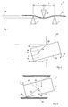
- a banknote conveyor 10 operates by the frictional engagement of three elements 14, 16 and 18 with a banknote 12.
- the elements 14, 16 and 18 move to convey the banknote 12 in a desired direction.
- These elements move in a plane perpendicular to, or in a plane parallel to, the plane of the drawing to convey the banknote.
- the operation of the invention is not however dependent on the direction of this movement. Both modes of operation are described below with reference to Figures 2 and 3.
- X is the distance between elements 16 and 14, Y the distance between elements 14 and 18 and D the degree of overlap between element 14 and elements 16 and 18 in the plane defined by the banknote 12 and defines the amount by which the banknote is deformed.
- the degree of force which is exerted by the elements 14, 16 and 18 on the banknote 12 will depend on the distances X, Y and D and on the rigidity of the note 12. If the distances X, Y and D are maintained as constant, the force will depend only on the rigidity of the note.
- Figure 2 is a plan view of a bezel 20 incorporating the apparatus of Figure 1 illustrating a first mode of operation of the apparatus.
- the elements 14, 16 and 18 move by rotating in a plane perpendicular to the plane of the drawing of Figure 1 and the banknote 12 is conveyed in the direction of arrow 22. This is part of the process of the uptake of the banknote 12 by the bezel 20. This movement will cause the side 24 of the banknote to come into contact with a reference surface such as a comer 26 of the bezel.
- the reaction of the comer 26 against the banknote 12 will encourage the banknote to swivel in the direction of arrow 28 with a force dependent on a distance R between the comer 26 and a point 30 about which the banknote swivels.
- Figure 3 illustrates the apparatus of Figure 1 installed in an aligner 30.
- the elements 14, 16 and 18 rotate in a plane parallel to the plane of the drawing of Figure 1 to move the banknote 12 in the direction of arrow 32.
- This movement brings a comer 34 of the banknote 12 into engagement with a reference surface 36 causing it to swivel in the direction of arrow 38.
- the force which causes banknote 12 to swivel about a point 40 is proportional to the distance R' between comer 34 and the point 40.
- the elements 14, 16 and 18 engage the banknote with a force which is dependent on the rigidity of the banknote and this allows movement of the banknote relative to any of these points allowing the banknote to swivel.
- the locations of the points 30 and 40 about which the banknote swivels will vary. These may be located at the point of contact of any one of the elements 14, 16 or 18 with the banknote or may (if the banknote moves relative to all three elements) be located between those points of contact.
- distances X, Y and D Figure 1
- distances X, Y and D Figure 1
- the placement of the elements 14, 16 and 18 relative to the comer 26 or the reference surface 36 so that for any banknote the rotational force due to movement against the comer 26 or the reference surface 36 will overcome the force exerted by the elements 14, 16 and 18, causing the banknote to move relative to one or more of those points and rotate.
- undesirable folding or bending of the banknote may be prevented.
- FIGS 1, 2 and 3 illustrate three elements 14, 16 and 18 which engage with the banknote 12, the principles described above are equally applicable to banknote conveyors which include a greater number of points of contact with a banknote.
- FIGS. 4 to 10 illustrate various embodiments incorporating the principles set out above.
- Figure 4 illustrates a banknote conveyor 50.
- a first cam 52 rotates in the direction of arrow 54 and a second cam 56 rotates in the direction of arrow 58.
- Cam 56 is formed with an eccentric portion which includes two nodes 60 and 62 which complement a node 64 of the eccentric portion of cam 52.
- the nodes 60, 36 and 64 deform the banknote in the manner described in relation to Figure 1 and correspond to the elements 14, 16 and 18 of Figure 1.
- the nodes 60, 62 and 64 move in a direction parallel to the plane of the drawing.
- the banknote 12 is conveyed in the direction of arrow 66 with a force dependent on the rigidity of the banknote.
- Figure 5 illustrates a further banknote conveyor 70 where three rollers 72, 74 and 76 engage frictionally with the banknote 12. As the rollers 72, 74 and 76 rotate in the direction of respective arrows 78, 80 and 82, the banknote 12 is conveyed in the direction of arrow 84 with a force dependent on the rigidity.
- the rollers 72, 74 and 76 correspond to the elements 14, 16 and 18 of Figure 1.
- FIG. 6 illustrates a further embodiment of the invention.
- Two uptake rollers 80 and 82 are formed with raised portions 84 and indented portions 86 to form corrugations.
- the uptake rollers 80 and 82 are arranged so that the respective raised portions 84 of one roller complement the indented portions 86 of the other roller.
- the banknote 12 is frictionally engaged by the raised and indented portions in the manner described in relation to Figure 1.
- the raised 84 and indented 86 portions of the rollers correspond to the elements 14, 16 and 18 of Figure 1.
- Rollers 80 and 82 define a gap D' through which the banknote 12 is conveyed.
- the size of the gap D' is 0.2 mm but it is to be realised that a number of other factors such as the coefficients of friction of the rollers 80 and 82 will also influence the force with which the banknote is conveyed. The size of the gap D' may therefore be altered to compensate for such other factors.
- the uptake rollers 80 and 82 rotate about respective axes 88 and 90 in the direction of respective arrows 92 and 94. As the uptake rollers 80 and 82 rotate, the banknote is frictionally engaged by the complementary raised and indented portions of the rollers and thereby conveyed.
- Figure 7 is a plan view of the mechanism of Figure 5 and illustrates the uptake roller 82 installed in a support 96 with respect to which the uptake roller 82 rotates.
- the roller is rotated by action on the cog 98.
- the support 96 includes a plate 100 which is formed to complement the raised portions 84 and the indented portions 86 of uptake roller 82 so that a minimal space exists between the plate 100 and the uptake roller 82. This prevents a banknote becoming frictionally engaged with the uptake roller 82 and being wrapped around the roller as opposed to being transported to the desired location.
- the same geometry is used for the roller 80.
- the uptake mechanism illustrated in Figures 6 and 7 has the advantage that the undulate banknote path defined by the gap between the uptake rollers 80 and 82 prevents rigid objects such as credit cards from being inserted into the mechanism.
- the uptake rollers 80 and 82 may also be brought into contact with one another to provide a seal. This is useful during a cleaning process, particularly when a high pressure water jet is used.
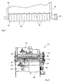
- a banknote uptake and alignment device 110 includes engaging uptake rollers 80 and 82 which have respective cogs 98 and 112 which engage with one another so that the uptake rollers 80 and 82 are driven at the same rate.
- the device 110 further includes a gripping roller 114 and three aligning rollers 116, 118 and 120. Roller 120 is orientated below and in between the rollers 116 and 118 in the configuration shown in Figure 5.
- a motor 122 drives the aligning rollers 116, 118 and 120 by means of a belt 124.
- the device 110 also includes two additional gripping rollers 126 and 128.
- a second motor 130 drives a belt 132 which, by means of axes 134, 136 and 138 drives respective rollers 114, 126 and 128.
- the belt 132 also drives a cog 140 which, in turn, is engaged with a cog 142 which drives the cog 98 of uptake roller 80.
- cog 140 also drives a cog 144 which is engaged with the cog 112 of uptake roller 82 which is driven thereby.
- the motor 130 therefore controls the movement of the uptake rollers 80 and 82 as well as the gripping rollers 114, 126 and 128.
- a banknote 12 ( Figure 9) is inserted in the direction of arrow 146.
- a sensor (not shown) senses that the banknote has been inserted and activates the motor 130 which causes the uptake rollers 80 and 82 to rotate.
- the uptake rollers engage frictionally with the banknote and cause it to be conveyed further in the direction of arrow 146 with a force which is dependent on the rigidity of the banknote due to the deformation of the note caused by the complementary surfaces of the rollers 80 and 82.
- the points of contact of the rollers 80 and 82 with the banknote also facilitate slippage of the note relative to the rollers.
- the motor 130 is stopped and the motor 122 is activated, driving the alignment rollers 116, 118 and 120 and conveying the banknote in the direction of arrow 146.
- This will cause the comer 152 of the banknote 12 to engage with the reference surface 154 and the banknote to swivel around this comer until its side 156 is aligned against the reference surface 154. This corresponds to the mode of operation described above with reference to Figure 3.
- the roller 114 conveys the banknote 12 from the uptake to the alignment rollers and rollers 126 and 128 convey the banknote 12 further.
- the device 110 is generally installed in a banknote changer (not shown) which is installed in a vending machine (not shown). The banknote is further transported to a banknote store or to other functional areas of the vending machine.
Landscapes
- Engineering & Computer Science (AREA)
- Mechanical Engineering (AREA)
- Delivering By Means Of Belts And Rollers (AREA)
- Registering Or Overturning Sheets (AREA)
Abstract
A banknote conveyor (10) which includes moveable means for
transporting the banknote which engage frictionally with the banknote
(12) at at least three points (14,16,18) so that the force
driving the banknote is dependent on the rigidity of the note. The
banknote (12) can further swivel about one of the points to align the
note with a desired path.
Description
- The invention relates to the transport of banknotes or other sheets of value, which are referred to simply as banknotes. The invention will be described in relation to banknote changers which are used in change machines and vending machines to receive, transport, store and dispense banknotes.
- Specifically, the invention is concerned with the uptake and alignment of banknotes. The uptake of banknotes involves the initial engagement of the banknote by the mechanism of the changer. Aligning is necessary so that the banknote has the correct orientation when transported to other functional units of the changer such as an acceptor where the banknote is verified. Misalignment of the banknote can cause jamming of the mechanisms in the changer and incorrect verification.
- A number of methods and associated apparatus are known in the art for the uptake of banknotes. The most common method is to pinch the note between two rollers and convey the note by rotating the rollers. The banknote is then aligned by being conveyed against a reference surface so that the reaction of the surface against the moving note causes the note to swivel and thereby align with the reference surface.
- This method exhibits a number of disadvantages. The force exerted by the rollers on the banknote is constant. Banknotes are variable in quality and a poor quality banknote is less rigid than a better quality banknote. On occasion, a jam in the uptake or alignment mechanism will occur when a poor quality banknote is conveyed against a reference surface causing the banknote to fold instead of swivel, resulting in a misalignment of the note and a subsequent jam. A further disadvantage is that rigid objects such as credit cards may be inserted into the uptake mechanism which may jam the mechanism.
- It is however desirable to use as great a force as possible when conveying the banknote to ensure that the banknote is properly aligned.
- Another method of banknote uptake involves creating a suction by use of a fan to displace air. The force of the suction is then used to engage the banknote with a driving belt. Although this arrangement lessens the incidents of jamming, banknotes which are crumpled or have lengthwise creases may still cause a jam.
- WO-A-02/49945 discloses apparatus for transporting a banknote which includes a curved transport path so that a banknote being transported is bent to increase its rigidity.
- It is an object of the invention to provide a banknote uptake and alignment mechanism which prevents the insertion of rigid objects and avoids jams caused by poor quality banknotes.
- Aspects of the invention are set out in the accompanying claims.
- In a further aspect of the invention a banknote conveyor engages a banknote with a force which is dependent on the rigidity of the banknote.
- Preferably, the conveyor engages frictionally with and bends the banknote so that the frictional force between the conveyor and the banknote is dependent on the rigidity of the banknote.
- The banknote conveyor may engage the banknote at a plurality of points.
- The banknote conveyor may further convey the banknote against a first reference surface so that the banknote rotates, moving relative to at least one of the points.
- The points are preferably arranged to maximise the distance between a point of rotation and a point of contact of the banknote with the reference surface.
- The banknote conveyor may convey the banknote against any one of two reference surfaces and the points may be arranged so that a force due to the conveyor is applied near a middle of the banknote when rotated.
- The banknote conveyor may define a banknote path which includes a plurality of contacts which engage with a banknote, at least two of the contacts engaging the banknote on opposite sides of the banknote.
- The points of contact may form part of an undulatory surface. In a preferred embodiment, the banknote path is defined by two spaced, complementary surfaces. The surfaces may be spaced by a gap defining a banknote path which may be in the range of 0.1 mm to 3 mm and is preferably 1.5 mm. This distance will depend on, among others, the number of points of contact and the coefficient of friction of the material of the points of contact.
- The conveyor may include at least two cams, each engaging the banknote at a point. Preferably, a first cam engages the note at two, spaced locations and a second cam engages the banknote at a third point located on an opposite face of the banknote and the cams rotate to convey the banknote.
- In yet a further aspect of the invention, the banknote conveyor includes a plurality of corrugated rollers which rotate to convey the banknote.
- A preferred embodiment incorporates a banknote uptake and a banknote aligner, both incorporating aspects of the invention. In the drawings and accompanying description which follow, like reference numerals are used to denote common features.
- Arrangements embodying the invention will now be described by way of example with reference to the accompanying drawings, in which:
- Figure 1 is a schematic view illustrating the operation of a banknote conveyor according to the invention;
- Figure 2 is a plan view of the apparatus of Figure 1 arranged to operate in a first mode;
- Figure 3 is a plan view of the apparatus of Figure 1 arranged to operate in a second mode;
- Figure 4 is a schematic view of a banknote conveyor according to an embodiment of the invention;
- Figure 5 is a schematic view of a banknote conveyor according to a further embodiment of the invention;
- Figure 6 is a schematic view of a banknote conveyor according to yet a further embodiment of the invention;
- Figure 7 is a top view of the conveyor of Figure 6 which has been installed in a support;
- Figure 8 is an end view of a banknote uptake and alignment device according to the invention incorporating the mechanism of Figure 6;
- Figure 9 is a top view of the device of Figure 8; and
- Figure 10 is an isometric view of the device of Figure 8.
-
- Referring to Figure 1, a
banknote conveyor 10 operates by the frictional engagement of threeelements banknote 12. Theelements banknote 12 in a desired direction. These elements move in a plane perpendicular to, or in a plane parallel to, the plane of the drawing to convey the banknote. The operation of the invention is not however dependent on the direction of this movement. Both modes of operation are described below with reference to Figures 2 and 3. - X is the distance between
elements elements element 14 andelements banknote 12 and defines the amount by which the banknote is deformed. The degree of force which is exerted by theelements banknote 12 will depend on the distances X, Y and D and on the rigidity of thenote 12. If the distances X, Y and D are maintained as constant, the force will depend only on the rigidity of the note. - Figure 2 is a plan view of a
bezel 20 incorporating the apparatus of Figure 1 illustrating a first mode of operation of the apparatus. Theelements banknote 12 is conveyed in the direction ofarrow 22. This is part of the process of the uptake of thebanknote 12 by thebezel 20. This movement will cause theside 24 of the banknote to come into contact with a reference surface such as acomer 26 of the bezel. As the banknote is conveyed, the reaction of thecomer 26 against thebanknote 12 will encourage the banknote to swivel in the direction ofarrow 28 with a force dependent on a distance R between thecomer 26 and apoint 30 about which the banknote swivels. - Figure 3 illustrates the apparatus of Figure 1 installed in an
aligner 30. In this mode of operation, theelements banknote 12 in the direction ofarrow 32. This movement brings acomer 34 of thebanknote 12 into engagement with areference surface 36 causing it to swivel in the direction of arrow 38. - The force which causes
banknote 12 to swivel about apoint 40 is proportional to the distance R' between comer 34 and thepoint 40. - As previously described, the
elements points elements - It is therefore possible to arrange distances X, Y and D (Figure 1) as well as the placement of the
elements comer 26 or thereference surface 36 so that for any banknote the rotational force due to movement against thecomer 26 or thereference surface 36 will overcome the force exerted by theelements - For a given arrangement such as that illustrated in Figures 1 and 2, a less rigid banknote will undergo less force when coming into contact with the
comer 26 or thereference surface 36 than a more rigid banknote would. A less rigid banknote will therefore be less susceptible to undesirable folding or bending than it would be in an arrangement which conveyed all banknotes with an unvarying force. - For each arrangement it is possible that more than one reference surface (or comer) is provided against which the banknote reacts to cause rotation. Furthermore, to encourage this rotation the direction of movement of the banknote may be inclined relative to a given reference surface.
- Although Figures 1, 2 and 3 illustrate three
elements banknote 12, the principles described above are equally applicable to banknote conveyors which include a greater number of points of contact with a banknote. - Figures 4 to 10 illustrate various embodiments incorporating the principles set out above.
- Figure 4 illustrates a
banknote conveyor 50. Afirst cam 52 rotates in the direction ofarrow 54 and asecond cam 56 rotates in the direction ofarrow 58.Cam 56 is formed with an eccentric portion which includes twonodes node 64 of the eccentric portion ofcam 52. Thenodes elements nodes - As the
cams banknote 12 is conveyed in the direction ofarrow 66 with a force dependent on the rigidity of the banknote. - Figure 5 illustrates a
further banknote conveyor 70 where threerollers banknote 12. As therollers respective arrows banknote 12 is conveyed in the direction ofarrow 84 with a force dependent on the rigidity. In this embodiment, therollers elements - Figure 6 illustrates a further embodiment of the invention. Two
uptake rollers portions 84 andindented portions 86 to form corrugations. Theuptake rollers portions 84 of one roller complement theindented portions 86 of the other roller. Provided that a degree of overlap between the respective raised and lowered portions of theuptake rollers banknote 12 is frictionally engaged by the raised and indented portions in the manner described in relation to Figure 1. The raised 84 and indented 86 portions of the rollers correspond to theelements -
Rollers banknote 12 is conveyed. By varying the size of the gap D', the force with which the rollers engage the banknote is varied. The size of the gap in the embodiment illustrated is 0.2 mm but it is to be realised that a number of other factors such as the coefficients of friction of therollers - The
uptake rollers respective axes 88 and 90 in the direction ofrespective arrows uptake rollers - Although there are more than three points of contact with the
banknote 12, the force with which the banknote is conveyed is nonetheless dependent on the rigidity of the banknote. - Figure 7 is a plan view of the mechanism of Figure 5 and illustrates the
uptake roller 82 installed in asupport 96 with respect to which theuptake roller 82 rotates. The roller is rotated by action on thecog 98. Thesupport 96 includes aplate 100 which is formed to complement the raisedportions 84 and theindented portions 86 ofuptake roller 82 so that a minimal space exists between theplate 100 and theuptake roller 82. This prevents a banknote becoming frictionally engaged with theuptake roller 82 and being wrapped around the roller as opposed to being transported to the desired location. The same geometry is used for theroller 80. - The uptake mechanism illustrated in Figures 6 and 7 has the advantage that the undulate banknote path defined by the gap between the
uptake rollers uptake rollers - With reference to Figures 8, 9 and 10 a banknote uptake and
alignment device 110 includes engaginguptake rollers respective cogs uptake rollers device 110 further includes agripping roller 114 and three aligningrollers Roller 120 is orientated below and in between therollers motor 122 drives the aligningrollers belt 124. Thedevice 110 also includes two additionalgripping rollers - A
second motor 130 drives abelt 132 which, by means ofaxes respective rollers belt 132 also drives acog 140 which, in turn, is engaged with acog 142 which drives thecog 98 ofuptake roller 80. Similarly,cog 140 also drives acog 144 which is engaged with thecog 112 ofuptake roller 82 which is driven thereby. Themotor 130 therefore controls the movement of theuptake rollers rollers - The operation of the
device 110 will now be described. A banknote 12 (Figure 9) is inserted in the direction ofarrow 146. A sensor (not shown) senses that the banknote has been inserted and activates themotor 130 which causes theuptake rollers arrow 146 with a force which is dependent on the rigidity of the banknote due to the deformation of the note caused by the complementary surfaces of therollers rollers banknote 12 is inserted so that its path causes a collision with acomer 150 of thedevice 90, the reaction of thecomer 150 on thebanknote 12 swivels the banknote thereby correcting its path. This prevents possible folding of the note which could result in the banknote becoming jammed or not being correctly verified. This corresponds to the mode of operation described above with reference to Figure 2. - Once the banknote has cleared the
uptake rollers elements motor 130 is stopped and themotor 122 is activated, driving thealignment rollers arrow 146. This will cause thecomer 152 of thebanknote 12 to engage with thereference surface 154 and the banknote to swivel around this comer until itsside 156 is aligned against thereference surface 154. This corresponds to the mode of operation described above with reference to Figure 3. - The
roller 114 conveys thebanknote 12 from the uptake to the alignment rollers androllers banknote 12 further. Thedevice 110 is generally installed in a banknote changer (not shown) which is installed in a vending machine (not shown). The banknote is further transported to a banknote store or to other functional areas of the vending machine.
Claims (18)
- A method of conveying a banknote which involves the steps offrictionally engaging at least three points with the banknote so as to partially deform the banknote, two of the points engaging opposite faces of the banknote; andmoving the points in a direction of intended movement of the banknote so that, at least during conveyance of the banknote, the points have a fixed relative spacing for any given position of the points and for any given banknote.
- A method according to claim 1 wherein the at least one point moves to convey the banknote against a reference surface to align the banknote.
- A method according to claim 1 or 2 wherein the points are arranged in a line.
- A method according to any preceding claim which includes the further step of moving the banknote relative to at least one point while moving the said points.
- A method according to claim 4 which includes the step of swivelling the banknote about at least one of said points while moving the points to align the banknote.
- A method of conveying a banknote which includes the step of deforming the banknote along at least two substantially parallel line.
- A method according to claim 6 which includes the step of bending the banknote at least twice.
- A banknote conveyor which includes at least two surfaces which frictionally engage opposite sides of a banknote so as to deform the banknote and which move to transport the banknote,
said surfaces being arranged so that, at least during transport of the banknote, the surfaces have a fixed relative spacing for any given position of the surfaces and for any given banknote. - A banknote conveyor according to claim 8 which includes a reference surface against which the banknote is conveyed.
- A banknote conveyor according to claim 8 or 9 wherein the said surfaces define at least three points of engagement with the banknote.
- A banknote conveyor according to claim 9 wherein the banknote moves relative to at least one point while being conveyed.
- A banknote conveyor according to any one of claims 8 to 11 which includes a first and a second corrugated roller.
- A banknote conveyor according to claim 12 wherein the first and the second rollers are engageable to create a seal.
- A banknote conveyor according to any one of claims 8 to 11 which includes a first and a second cam.
- A banknote conveyor according to any one of claims 8 to 11 which includes three rollers.
- A banknote conveyor which includes at least two surfaces moveable between a first position and a second position so that in the first position the surfaces define an undulate banknote path and in the second position the surfaces engage to provide a seal.
- A banknote changer comprising banknote uptake means and banknote alignment means, the uptake and alignment means each further comprising a banknote conveyor of any one of claims 8 or 16.
- A banknote conveyor which engages a banknote by means of surfaces which define a gap of predetermined configuration which is wider than the thickness of the banknote and of non-linear configuration so as to cause bending of the banknote when viewed in the direction of transport so that the force by which the banknote is gripped is dependent upon the rigidity of the banknote.
Priority Applications (10)
| Application Number | Priority Date | Filing Date | Title |
|---|---|---|---|
| EP02258869A EP1433728A1 (en) | 2002-12-23 | 2002-12-23 | Banknote conveyor |
| DE60331952T DE60331952D1 (en) | 2002-12-23 | 2003-12-19 | CONVEYOR FOR BANKNOTE |
| AU2003293980A AU2003293980A1 (en) | 2002-12-23 | 2003-12-19 | Banknote conveyor |
| PCT/EP2003/014783 WO2004056684A2 (en) | 2002-12-23 | 2003-12-19 | Banknote conveyor |
| JP2004561425A JP5014578B2 (en) | 2002-12-23 | 2003-12-19 | Bill transporter |
| ES03789393T ES2342057T3 (en) | 2002-12-23 | 2003-12-19 | TRANSPORTATION DEVICE FOR BANK TICKETS. |
| EP03789393A EP1578682B1 (en) | 2002-12-23 | 2003-12-19 | Banknote conveyor |
| US10/539,524 US7556264B2 (en) | 2002-12-23 | 2003-12-19 | Banknote conveyor |
| CN2003801099315A CN1753821B (en) | 2002-12-23 | 2003-12-19 | Banknote conveyor |
| JP2010129879A JP5368378B2 (en) | 2002-12-23 | 2010-06-07 | Bill transporter |
Applications Claiming Priority (1)
| Application Number | Priority Date | Filing Date | Title |
|---|---|---|---|
| EP02258869A EP1433728A1 (en) | 2002-12-23 | 2002-12-23 | Banknote conveyor |
Publications (1)
| Publication Number | Publication Date |
|---|---|
| EP1433728A1 true EP1433728A1 (en) | 2004-06-30 |
Family
ID=32405787
Family Applications (2)
| Application Number | Title | Priority Date | Filing Date |
|---|---|---|---|
| EP02258869A Withdrawn EP1433728A1 (en) | 2002-12-23 | 2002-12-23 | Banknote conveyor |
| EP03789393A Expired - Lifetime EP1578682B1 (en) | 2002-12-23 | 2003-12-19 | Banknote conveyor |
Family Applications After (1)
| Application Number | Title | Priority Date | Filing Date |
|---|---|---|---|
| EP03789393A Expired - Lifetime EP1578682B1 (en) | 2002-12-23 | 2003-12-19 | Banknote conveyor |
Country Status (8)
| Country | Link |
|---|---|
| US (1) | US7556264B2 (en) |
| EP (2) | EP1433728A1 (en) |
| JP (2) | JP5014578B2 (en) |
| CN (1) | CN1753821B (en) |
| AU (1) | AU2003293980A1 (en) |
| DE (1) | DE60331952D1 (en) |
| ES (1) | ES2342057T3 (en) |
| WO (1) | WO2004056684A2 (en) |
Cited By (3)
| Publication number | Priority date | Publication date | Assignee | Title |
|---|---|---|---|---|
| DE102007020778A1 (en) * | 2007-05-03 | 2008-11-06 | Giesecke & Devrient Gmbh | Device for handling value documents |
| DE102007059390B3 (en) * | 2007-12-10 | 2009-06-25 | Eastman Kodak Company | Paper transporting unit for e.g. inkjet printer, has guide units arranged on sides of rollers and defining wavy guidance path, and housing cover suspended around pivotable axis such that it is pivoted away relative to another housing cover |
| DE102008050524A1 (en) * | 2008-10-06 | 2010-04-08 | Wincor Nixdorf International Gmbh | Device for aligning notes of value |
Families Citing this family (9)
| Publication number | Priority date | Publication date | Assignee | Title |
|---|---|---|---|---|
| DE102004023909A1 (en) * | 2004-05-13 | 2005-12-08 | Atotech Deutschland Gmbh | transport device |
| US8348272B2 (en) * | 2006-10-24 | 2013-01-08 | Glory Ltd. | Sheets counting device |
| JP4936973B2 (en) * | 2007-04-26 | 2012-05-23 | ローレル機械株式会社 | Banknote storage device |
| CN102324136B (en) * | 2011-05-18 | 2013-06-26 | 广州广电运通金融电子股份有限公司 | Card information protection device and finance equipment provided with same |
| JP5608814B2 (en) * | 2011-05-25 | 2014-10-15 | 株式会社マースウインテック | Paper sheet identification device |
| US8910936B2 (en) * | 2013-04-22 | 2014-12-16 | International Currency Technologies Corporation | Bill position correction method using the characteristic of step loss of step motor |
| DE102013221236A1 (en) * | 2013-10-18 | 2015-04-23 | Ci Tech Components Ag | Feeding device for sheet material |
| CN107498774A (en) | 2016-06-14 | 2017-12-22 | 福特环球技术公司 | For manufacturing the system and method with weakened part moulding |
| CN106185449B (en) * | 2016-06-30 | 2018-06-26 | 广州广电运通金融电子股份有限公司 | Laminated dielectric flattening device and financial self-service equipment |
Citations (5)
| Publication number | Priority date | Publication date | Assignee | Title |
|---|---|---|---|---|
| GB699071A (en) * | 1949-07-15 | 1953-10-28 | Kodak Ltd | Improvements in means for the transport of sheet material |
| US4106767A (en) * | 1975-12-12 | 1978-08-15 | G.A.O. Gesellschaft Fur Automation Und Organisation Mbh | Conveyor system for flat articles |
| EP0749926A1 (en) * | 1994-03-03 | 1996-12-27 | Kabushiki Kaisha Ace Denken | Paper slip storage unit |
| US20010045697A1 (en) * | 2000-02-09 | 2001-11-29 | Jerome Daout | Self aligning transport mechanism for media of variable media widths |
| EP1167260A2 (en) * | 2000-06-20 | 2002-01-02 | Hitachi, Ltd. | Paper money handling device |
Family Cites Families (15)
| Publication number | Priority date | Publication date | Assignee | Title |
|---|---|---|---|---|
| JPS55113338U (en) * | 1979-02-01 | 1980-08-09 | ||
| JPS60170344U (en) * | 1984-04-18 | 1985-11-12 | 株式会社リコー | Recording paper ejection device in image forming apparatus |
| US4971304A (en) * | 1986-12-10 | 1990-11-20 | Xerox Corporation | Apparatus and method for combined deskewing and side registering |
| JPH0210338A (en) * | 1988-06-29 | 1990-01-16 | Toshiba Corp | Image forming device |
| JPH033850A (en) * | 1989-06-01 | 1991-01-09 | Hitachi Ltd | statement issuing machine |
| JPH0389050A (en) * | 1989-08-30 | 1991-04-15 | Mitsuboshi Belting Ltd | High load transmitting belt |
| US5078384A (en) * | 1990-11-05 | 1992-01-07 | Xerox Corporation | Combined differential deskewing and non-differential registration of sheet material using plural motors |
| JP2986203B2 (en) * | 1990-11-29 | 1999-12-06 | 株式会社日立製作所 | Card handling device |
| JP2710916B2 (en) * | 1994-08-10 | 1998-02-10 | ミュー株式会社 | Banknote counter |
| JP3545116B2 (en) * | 1995-11-28 | 2004-07-21 | 三洋電機株式会社 | Bill transporter |
| JPH09315652A (en) * | 1996-05-23 | 1997-12-09 | Toyo Commun Equip Co Ltd | Paper sheet correction mechanism |
| JP3361979B2 (en) * | 1996-12-09 | 2003-01-07 | ローレルバンクマシン株式会社 | Banknote aligner of banknote processing machine |
| JP3738946B2 (en) * | 1999-03-24 | 2006-01-25 | コニカミノルタビジネステクノロジーズ株式会社 | Paper curl correction device |
| JP2001253613A (en) * | 2000-03-14 | 2001-09-18 | Sharp Corp | Paper transport mechanism |
| DE10062807C2 (en) * | 2000-12-15 | 2003-02-06 | Siemens Metering Ag Zug | Unidirectional counter |
-
2002
- 2002-12-23 EP EP02258869A patent/EP1433728A1/en not_active Withdrawn
-
2003
- 2003-12-19 JP JP2004561425A patent/JP5014578B2/en not_active Expired - Fee Related
- 2003-12-19 EP EP03789393A patent/EP1578682B1/en not_active Expired - Lifetime
- 2003-12-19 ES ES03789393T patent/ES2342057T3/en not_active Expired - Lifetime
- 2003-12-19 WO PCT/EP2003/014783 patent/WO2004056684A2/en not_active Ceased
- 2003-12-19 CN CN2003801099315A patent/CN1753821B/en not_active Expired - Lifetime
- 2003-12-19 US US10/539,524 patent/US7556264B2/en not_active Expired - Fee Related
- 2003-12-19 AU AU2003293980A patent/AU2003293980A1/en not_active Abandoned
- 2003-12-19 DE DE60331952T patent/DE60331952D1/en not_active Expired - Lifetime
-
2010
- 2010-06-07 JP JP2010129879A patent/JP5368378B2/en not_active Expired - Fee Related
Patent Citations (5)
| Publication number | Priority date | Publication date | Assignee | Title |
|---|---|---|---|---|
| GB699071A (en) * | 1949-07-15 | 1953-10-28 | Kodak Ltd | Improvements in means for the transport of sheet material |
| US4106767A (en) * | 1975-12-12 | 1978-08-15 | G.A.O. Gesellschaft Fur Automation Und Organisation Mbh | Conveyor system for flat articles |
| EP0749926A1 (en) * | 1994-03-03 | 1996-12-27 | Kabushiki Kaisha Ace Denken | Paper slip storage unit |
| US20010045697A1 (en) * | 2000-02-09 | 2001-11-29 | Jerome Daout | Self aligning transport mechanism for media of variable media widths |
| EP1167260A2 (en) * | 2000-06-20 | 2002-01-02 | Hitachi, Ltd. | Paper money handling device |
Cited By (5)
| Publication number | Priority date | Publication date | Assignee | Title |
|---|---|---|---|---|
| DE102007020778A1 (en) * | 2007-05-03 | 2008-11-06 | Giesecke & Devrient Gmbh | Device for handling value documents |
| US7922173B2 (en) | 2007-05-03 | 2011-04-12 | Giesecke & Devrient Gmbh | Apparatus for handling documents of value |
| DE102007059390B3 (en) * | 2007-12-10 | 2009-06-25 | Eastman Kodak Company | Paper transporting unit for e.g. inkjet printer, has guide units arranged on sides of rollers and defining wavy guidance path, and housing cover suspended around pivotable axis such that it is pivoted away relative to another housing cover |
| DE102008050524A1 (en) * | 2008-10-06 | 2010-04-08 | Wincor Nixdorf International Gmbh | Device for aligning notes of value |
| US7950518B2 (en) | 2008-10-06 | 2011-05-31 | Wincor Nixdorf International Gmbh | Apparatus for aligning vouchers |
Also Published As
| Publication number | Publication date |
|---|---|
| JP5368378B2 (en) | 2013-12-18 |
| DE60331952D1 (en) | 2010-05-12 |
| JP2010205299A (en) | 2010-09-16 |
| JP2006511411A (en) | 2006-04-06 |
| WO2004056684A2 (en) | 2004-07-08 |
| CN1753821A (en) | 2006-03-29 |
| AU2003293980A8 (en) | 2004-07-14 |
| AU2003293980A1 (en) | 2004-07-14 |
| US7556264B2 (en) | 2009-07-07 |
| JP5014578B2 (en) | 2012-08-29 |
| CN1753821B (en) | 2013-07-17 |
| EP1578682A2 (en) | 2005-09-28 |
| US20060181014A1 (en) | 2006-08-17 |
| WO2004056684A3 (en) | 2004-11-25 |
| EP1578682B1 (en) | 2010-03-31 |
| ES2342057T3 (en) | 2010-07-01 |
Similar Documents
| Publication | Publication Date | Title |
|---|---|---|
| JP5368378B2 (en) | Bill transporter | |
| US7063472B2 (en) | Sheet skew correcting apparatus and image forming apparatus | |
| EP0764133B1 (en) | Automated teller machine passbook transport mechanism | |
| US5261655A (en) | Disk stacker with intermittent corrugation assistance for small sheets | |
| EP0232365B1 (en) | Sheet moving apparatus | |
| JP6764367B2 (en) | Paper leaf skew correction device | |
| CN111032545B (en) | Friction conveying device and paper conveying device | |
| WO2023181622A1 (en) | Friction conveyance device and paper sheet conveyance device | |
| JP7654607B2 (en) | Paper handling equipment | |
| CN111747161A (en) | Calibration mechanism and image forming apparatus | |
| EP2151407B1 (en) | Right angle turn (rat) module for conveying multi-sheet collations | |
| JP3853486B2 (en) | Paper transport device | |
| JP2642394B2 (en) | Paper transport device | |
| JPH05242337A (en) | Paper handling equipment | |
| KR102662867B1 (en) | Banknote processing apparatus | |
| RU2840174C2 (en) | Friction device for transportation and device for transportation of paper sheets | |
| JP3248349B2 (en) | Coin aligner | |
| EP0145113B1 (en) | A document conveyor system | |
| US20250066148A1 (en) | Sheet conveyance device with conveyance roller pair capable of conveying sheet | |
| AU775723B2 (en) | Sheet feeder | |
| JP2006338267A (en) | Bill conveyor | |
| JP2566384Y2 (en) | Bill handling equipment | |
| WO1996006789A1 (en) | Sidewise-moving mechanism in sheet conveying apparatus | |
| JPH04226224A (en) | Sheet material feeding device | |
| JPH03293246A (en) | Conveying mechanism for paper sheets |
Legal Events
| Date | Code | Title | Description |
|---|---|---|---|
| PUAI | Public reference made under article 153(3) epc to a published international application that has entered the european phase |
Free format text: ORIGINAL CODE: 0009012 |
|
| AK | Designated contracting states |
Kind code of ref document: A1 Designated state(s): AT BE BG CH CY CZ DE DK EE ES FI FR GB GR IE IT LI LU MC NL PT SE SI SK TR |
|
| AX | Request for extension of the european patent |
Extension state: AL LT LV MK RO |
|
| AKX | Designation fees paid | ||
| REG | Reference to a national code |
Ref country code: DE Ref legal event code: 8566 |
|
| STAA | Information on the status of an ep patent application or granted ep patent |
Free format text: STATUS: THE APPLICATION IS DEEMED TO BE WITHDRAWN |
|
| 18D | Application deemed to be withdrawn |
Effective date: 20041231 |