EP1433712A1 - Dispensing cap with variable discharge - Google Patents
Dispensing cap with variable discharge Download PDFInfo
- Publication number
- EP1433712A1 EP1433712A1 EP02028908A EP02028908A EP1433712A1 EP 1433712 A1 EP1433712 A1 EP 1433712A1 EP 02028908 A EP02028908 A EP 02028908A EP 02028908 A EP02028908 A EP 02028908A EP 1433712 A1 EP1433712 A1 EP 1433712A1
- Authority
- EP
- European Patent Office
- Prior art keywords
- core
- crown
- base
- cap according
- container
- Prior art date
- Legal status (The legal status is an assumption and is not a legal conclusion. Google has not performed a legal analysis and makes no representation as to the accuracy of the status listed.)
- Withdrawn
Links
Images


Classifications
-
- B—PERFORMING OPERATIONS; TRANSPORTING
- B65—CONVEYING; PACKING; STORING; HANDLING THIN OR FILAMENTARY MATERIAL
- B65D—CONTAINERS FOR STORAGE OR TRANSPORT OF ARTICLES OR MATERIALS, e.g. BAGS, BARRELS, BOTTLES, BOXES, CANS, CARTONS, CRATES, DRUMS, JARS, TANKS, HOPPERS, FORWARDING CONTAINERS; ACCESSORIES, CLOSURES, OR FITTINGS THEREFOR; PACKAGING ELEMENTS; PACKAGES
- B65D47/00—Closures with filling and discharging, or with discharging, devices
- B65D47/04—Closures with discharging devices other than pumps
- B65D47/20—Closures with discharging devices other than pumps comprising hand-operated members for controlling discharge
- B65D47/30—Closures with discharging devices other than pumps comprising hand-operated members for controlling discharge with plug valves, i.e. valves that open and close a passageway by turning a cylindrical or conical plug without axial passageways
-
- B—PERFORMING OPERATIONS; TRANSPORTING
- B65—CONVEYING; PACKING; STORING; HANDLING THIN OR FILAMENTARY MATERIAL
- B65D—CONTAINERS FOR STORAGE OR TRANSPORT OF ARTICLES OR MATERIALS, e.g. BAGS, BARRELS, BOTTLES, BOXES, CANS, CARTONS, CRATES, DRUMS, JARS, TANKS, HOPPERS, FORWARDING CONTAINERS; ACCESSORIES, CLOSURES, OR FITTINGS THEREFOR; PACKAGING ELEMENTS; PACKAGES
- B65D47/00—Closures with filling and discharging, or with discharging, devices
- B65D47/04—Closures with discharging devices other than pumps
- B65D47/20—Closures with discharging devices other than pumps comprising hand-operated members for controlling discharge
- B65D47/26—Closures with discharging devices other than pumps comprising hand-operated members for controlling discharge with slide valves, i.e. valves that open and close a passageway by sliding over a port, e.g. formed with slidable spouts
- B65D47/261—Closures with discharging devices other than pumps comprising hand-operated members for controlling discharge with slide valves, i.e. valves that open and close a passageway by sliding over a port, e.g. formed with slidable spouts having a rotational or helicoidal movement
- B65D47/266—Closures with discharging devices other than pumps comprising hand-operated members for controlling discharge with slide valves, i.e. valves that open and close a passageway by sliding over a port, e.g. formed with slidable spouts having a rotational or helicoidal movement the rotational movement being transmitted by displacement of an additional external element, e.g. overcap
Definitions
- the present invention relates to a variable flow distributor cap plus particularly intended for containers of liquid food products such as drinks.
- Such caps include a fixing base secured to the container neck and a distributor connected to said base while being movable in axial translation so as to allow adjustment of the liquid flow rate during gravity flow.
- the distributor consists of a plug comprising, on the one hand, a internal core carried in a movable and sealed manner by said base and provided with a conduit evacuation, and, on the other hand, an external crown mounted on said base by covering said core and ensuring, by rotation, in engagement with transmission means, the pivoting of said core and placing the container in communication with the outside via the exhaust duct and through said crown.
- said core comprises two lateral pivots resting in support slots provided on said base.
- said transmission means consist of complementary toothed zones engaged with one another by forming gears, formed respectively, on the underside of said crown and on said core.
- said base comprises an external skirt provided with retaining members on the container neck and an internal jacket provided with a sealing element with said core.
- said slots are made at the top of said shirt while said sealing element is formed by an internal lip in rotary contact with said core.
- said base comprises an upper flange provided with a snap ring of said crown.
- said crown is connected to the base by a separable tamper-evident band.
- said core is formed of a sphere with a conduit axial evacuation.
- the inner edge of the crown is provided with a flexible lip external seal and said core or at least said discharge duct projects at across said crown.
- the plug of the invention offers an aesthetic and very ergonomic profile, the compactness is close to that of a traditional cork, in particular because the bushel is housed inside the container neck.
- the structure of the cap is simple and the number of pieces sufficiently limited to make its manufacturing process quick and economical.
- the tightness of the container is very high due, on the one hand, to the possibility of locking the valve plug in the closed position and, on the other hand, of the joint action of the internal and external lips coming laterally in contact with support against said bushel.
- the operation of the crown is carried out very easily in the manner of a dial and allows precise and reliable adjustment of the liquid flow rate, suitable for different types of consumption.
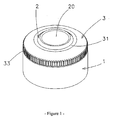
- the cap shown in Figure 1 is intended to be mounted on a container (not shown) of liquid food product (mineral water, milk, fruit juice, oil, etc.).
- liquid food product mineral water, milk, fruit juice, oil, etc.
- the assembly on the container can be done by snap as is provided in the embodiment shown or by any other means such as screwing.
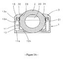
- the plug comprises a body formed by a base of attachment 1 covering the container, with an external skirt 11 which is made integral with the neck at by means of a retaining member 11a visible in FIGS. 3A and 3B.
- Another variant may consist in making the base directly in one piece with the neck of the container.
- the cap further comprises an adjustable distributor connected to the base 1.
- This dispenser consists, according to the invention, of a bushel comprising, of a part, an internal core 2 supported in a mobile and sealed manner by the base 1 and which is provided with an exhaust duct 20 and, on the other hand, an external crown 3 mounted on the base 1 by covering the core 2.
- the crown 3 is here snapped onto a rod 13a carried by an upper flange 13 produced on the base 1 while retaining freedom of rotation.
- the crown 3 ensures, by rotation in the manner of a dial and in engagement with transmission means integrated into both the crown 3 and the core 2 (visible on the Figures 2 and 3A and 3B and described below), the pivoting of the core 2 as well as the communication of the container with the outside via the conduit 20, through the opening central 30 of the crown 3.
- the crown 3 is provided with lateral grooves 33.
- the core 2 which is here produced in spherical form with an evacuation duct axial, has two lateral pivots 21 resting in support slots 12a formed diametrically on the base 1.
- the axis of the pivots is perpendicular to the axis of the conduit 20.
- the slots 12a are located at the top of a shirt internal 12 produced coaxially with the skirt 11 on the base 1 and are associated with lights 14.
- the space 10 delimited by the respective walls of the skirt 11 and the shirt 12 is for its part intended to receive the neck of the container by fitting.
- the bottleneck container is thus in the axis of the jacket 12 and the core 2 is housed in large part inside the neck with minimum bulk.
- the jacket 12 is further provided, in its lower part, with a sealing element in the form of an internal lip 12b coming into contact with the core 2.
- the transmission means here consist of two toothed zones or tracks of complementary profiles 32, 23 engaged with each other by forming gears and / or pinions and which are formed respectively under the crown 3 and on the core 2.
- the track 23 of the core 2 is carried by a frustoconical boss 22 centered on one of the lateral pivots 21 while the track 32 of the crown is produced on an inclined portion from its underside.
- the cooperation of the zones 32, 23 also secures and locks the core 2 relative to the crown 3 in a determined position and thus makes it possible to obtain, during use, an adjustable and stable flow rate of liquid (corresponding to the total or partial opening of the conduit 20) and, during storage, a complete and watertight closure guarantee.
- an adjustable and stable flow rate of liquid corresponding to the total or partial opening of the conduit 20
- the geometry of the tracks 32, 23 is determined so that the passage from the full opening of the plug to its complete closing is possible with a sectoral rotation of the crown 3.
- the closing of the plug corresponds to an orientation of the axis of the conduit 20 at 90 ° the axis of the plug, as shown in Figure 3A. In this position, the conduit 20 is hidden and the solid wall of the core closes, at the bottom, the neck of the container.
- the core 2 or at least the conduit 20 protrudes through the crown 3 as is apparent on the Figures 3A and 3B.
- the diameter of the opening 30 of the crown 3 is greater the diameter of the conduit 20.
- the crown 3 is attached to the base 1 by a separable tamper-evident band 4 which prevents any rotation of the plug and preserves thus the integrity of the container.
- the strip 4 must obviously be sealed or overmolded with the base 1 and the crown 3 in the closed position of the plug.
Abstract
Description
La présente invention concerne un bouchon distributeur à débit variable plus particulièrement destiné aux récipients de produits alimentaires liquides tels que des boissons.The present invention relates to a variable flow distributor cap plus particularly intended for containers of liquid food products such as drinks.
Il existe des bouchons pour récipients de boissons (eaux minérales, jus de fruits...) permettant au consommateur d'effectuer l'ouverture et la fermeture du récipient uniquement avec la bouche. Ces bouchons sont destinés en priorité à des usages sportifs ou, plus généralement, de loisirs qualifiés de "nomades".There are caps for beverage containers (mineral waters, fruit juices ...) allowing the consumer to open and close the container only with the mouth. These plugs are primarily intended for sports uses or, more generally, of leisure qualified as "nomads".
De tels bouchons comprennent une embase de fixation solidaire du col de récipient et un distributeur raccordé à ladite embase en étant mobile en translation axiale de façon à permettre un réglage du débit de liquide lors de l'écoulement par gravité.Such caps include a fixing base secured to the container neck and a distributor connected to said base while being movable in axial translation so as to allow adjustment of the liquid flow rate during gravity flow.
Cependant, le réglage du débit reste aléatoire et l'herméticité du récipient en position d'obturation ne peut être garantie du fait qu'il n'existe pas de moyen de verrouillage de la position du bouchon. Les risques de fuite et d'altération ou de pollution du produit sont donc élevés surtout pour des utilisations de loisir en plein air.However, the adjustment of the flow remains random and the hermeticity of the container in shutter position cannot be guaranteed because there is no way to locking the plug position. The risks of leakage and alteration or pollution of the product are therefore high, especially for outdoor leisure uses.
En outre, ces bouchons sont relativement encombrants car le distributeur est disposé
à l'extérieur du col du récipient et travaille en extension entre ses positions de fermeture et
d'ouverture.
La présente invention a pour but de résoudre ces problèmes techniques de manière
satisfaisante. In addition, these plugs are relatively bulky because the dispenser is disposed outside the neck of the container and works in extension between its closed and open positions.
The present invention aims to solve these technical problems satisfactorily.
Ce but est atteint selon l'invention au moyen d'un bouchon du type précédent caractérisé en ce que le distributeur est constitué d'un boisseau comprenant, d'une part, un noyau interne porté de façon mobile et étanche par ladite embase et pourvu d'un conduit d'évacuation, et, d'autre part, une couronne externe montée sur ladite embase en coiffant ledit noyau et assurant, par rotation, en prise avec des moyens de transmission, le pivotement dudit noyau et la mise en communication du récipient avec l'extérieur via le conduit d'évacuation et au travers de ladite couronne.This object is achieved according to the invention by means of a plug of the previous type characterized in that the distributor consists of a plug comprising, on the one hand, a internal core carried in a movable and sealed manner by said base and provided with a conduit evacuation, and, on the other hand, an external crown mounted on said base by covering said core and ensuring, by rotation, in engagement with transmission means, the pivoting of said core and placing the container in communication with the outside via the exhaust duct and through said crown.
Selon une caractéristique avantageuse, ledit noyau comporte deux pivots latéraux reposant dans des créneaux de support ménagés sur ladite embase.According to an advantageous characteristic, said core comprises two lateral pivots resting in support slots provided on said base.
Selon une autre caractéristique, lesdits moyens de transmission sont constitués de zones dentées complémentaires engagées l'une avec l'autre en formant engrenages, ménagées respectivement, sur la face inférieure de ladite couronne et sur ledit noyau.According to another characteristic, said transmission means consist of complementary toothed zones engaged with one another by forming gears, formed respectively, on the underside of said crown and on said core.
Selon un mode de réalisation spécifique, ladite embase comporte une jupe externe pourvue d'organes de retenue sur le col du récipient et une chemise interne pourvue d'un élément d'étanchéité avec ledit noyau.According to a specific embodiment, said base comprises an external skirt provided with retaining members on the container neck and an internal jacket provided with a sealing element with said core.
De préférence, lesdits créneaux sont réalisés à la partie supérieure de ladite chemise tandis que ledit élément d'étanchéité est formé d'une lèvre interne en contact rotatif avec ledit noyau.Preferably, said slots are made at the top of said shirt while said sealing element is formed by an internal lip in rotary contact with said core.
Selon encore une autre caractéristique, ladite embase comporte une collerette
supérieure pourvue d'un jonc d'encliquetage de ladite couronne.
Selon une autre variante, ladite couronne est raccordée à l'embase par une bande
d'inviolabilité séparable. According to yet another characteristic, said base comprises an upper flange provided with a snap ring of said crown.
According to another variant, said crown is connected to the base by a separable tamper-evident band.
Selon encore une autre variante, ledit noyau est formé d'une sphère avec un conduit d'évacuation axial.According to yet another variant, said core is formed of a sphere with a conduit axial evacuation.
De préférence, le bord intérieur de la couronne est pourvu d'une lèvre souple externe d'étanchéité et ledit noyau ou au moins ledit conduit d'évacuation fait saillie au travers de ladite couronne.Preferably, the inner edge of the crown is provided with a flexible lip external seal and said core or at least said discharge duct projects at across said crown.
Le bouchon de l'invention offre un profil esthétique et très ergonomique dont la compacité est voisine de celle d'un bouchon traditionnel, en particulier du fait que le boisseau est logé à l'intérieur du col du récipient.The plug of the invention offers an aesthetic and very ergonomic profile, the compactness is close to that of a traditional cork, in particular because the bushel is housed inside the container neck.
La structure du bouchon est simple et le nombre de pièces suffisamment restreint pour rendre son procédé de fabrication rapide et économique.The structure of the cap is simple and the number of pieces sufficiently limited to make its manufacturing process quick and economical.
En outre, l'étanchéité du récipient est très poussée en raison d'une part, de la possibilité de verrouillage du boisseau distributeur en position de fermeture et, d'autre part, de l'action conjointe des lèvres interne et externe venant latéralement en contact d'appui contre ledit boisseau.In addition, the tightness of the container is very high due, on the one hand, to the possibility of locking the valve plug in the closed position and, on the other hand, of the joint action of the internal and external lips coming laterally in contact with support against said bushel.
Enfin, la manoeuvre de la couronne s'effectue très facilement à la manière d'une molette et permet un réglage précis et fiable du débit de liquide, adapté à différents types de consommations.Finally, the operation of the crown is carried out very easily in the manner of a dial and allows precise and reliable adjustment of the liquid flow rate, suitable for different types of consumption.
La présence optionnelle d'une ou deux bandes d'inviolabilité complète avantageusement les qualités de ce bouchon et augmente encore ses capacités d'adaptation et son attrait pour une clientèle variée. The optional presence of one or two complete tamper-evident tapes advantageously the qualities of this cap and further increases its adaptability and its attraction for a varied clientele.
L'invention sera mieux comprise à la lecture de la description qui va suivre en
référence aux dessins sur lesquels :
Le bouchon représenté sur la figure 1 est destiné à être monté sur un récipient (non représenté) de produit alimentaire liquide (eau minérale, lait, jus de fruits, huile....).The cap shown in Figure 1 is intended to be mounted on a container (not shown) of liquid food product (mineral water, milk, fruit juice, oil, etc.).
L'assemblage sur le récipient peut être effectué par encliquetage comme cela est prévu dans le mode de réalisation représenté ou par tout autre moyen tel qu'un vissage.The assembly on the container can be done by snap as is provided in the embodiment shown or by any other means such as screwing.
A cet effet, le bouchon comprend un corps formé d'une embase de
fixation 1 coiffant le récipient, avec une jupe externe 11 qui est rendue solidaire du col au
moyen d'un organe de retenue 11a apparent sur les figures 3A et 3B.To this end, the plug comprises a body formed by a base of
Une autre variante, non représentée, peut consister à réaliser directement l'embase
d'une seule pièce avec le col du récipient.
Le bouchon comprend en outre un distributeur réglable raccordé à l'embase 1. Another variant, not shown, may consist in making the base directly in one piece with the neck of the container.
The cap further comprises an adjustable distributor connected to the
Ce distributeur est constitué, selon l'invention, d'un boisseau comprenant, d'une
part, un noyau interne 2 supporté de façon mobile et étanche par l'embase 1 et qui est
pourvu d'un conduit d'évacuation 20 et, d'autre part, une couronne externe 3 monté sur
l'embase 1 en coiffant le noyau 2.This dispenser consists, according to the invention, of a bushel comprising, of a
part, an
Comme représenté sur les figures 3A et 3B, la couronne 3 est ici encliquetée sur un
jonc 13a porté par une collerette supérieure 13 réalisée sur l'embase 1 tout en conservant
une liberté de rotation.As shown in FIGS. 3A and 3B, the
La couronne 3 assure, par rotation à la manière d'une molette et en prise avec des
moyens de transmission intégrés à la fois à la couronne 3 et au noyau 2 (visibles sur les
figures 2 et 3A et 3B et décrits ci-après), le pivotement du noyau 2 ainsi que la mise en
communication du récipient avec l'extérieur via le conduit 20, au travers de l'ouverture
centrale 30 de la couronne 3.The
Pour faciliter sa préhension, la couronne 3 est pourvue de cannelures latérales 33.To facilitate gripping, the
Le noyau 2 qui est ici réalisé sous forme sphérique avec un conduit d'évacuation
axial, comporte deux pivots latéraux 21 reposant dans des créneaux de support 12a
ménagés de façon diamétrale sur l'embase 1. L'axe des pivots est perpendiculaire à l'axe du
conduit 20.The
Plus précisément, les créneaux 12a sont situés à la partie supérieure d'une chemise
interne 12 réalisée de façon coaxiale à la jupe 11 sur l'embase 1 et sont associés à des
lumières 14. L'espace 10 délimité par les parois respectives de la jupe 11 et de la chemise
12 est quant à lui destiné à recevoir le col du récipient par emmanchement. Le goulot du
récipient se trouve ainsi dans l'axe de la chemise 12 et le noyau 2 se trouve logé en grande
partie à l'intérieur du col avec un encombrement minimum. More specifically, the
La chemise 12 est pourvue en outre, dans sa partie basse, d'un élément d'étanchéité
sous forme d'une lèvre interne 12b venant en contact avec le noyau 2.The
Les moyens de transmission sont constitués ici de deux zones ou pistes dentées de
profils complémentaires 32, 23 engagées l'une avec l'autre en formant engrenages et/ou
pignons et qui sont ménagées respectivement sous la couronne 3 et sur le noyau 2.The transmission means here consist of two toothed zones or tracks of
La piste 23 du noyau 2 est portée par un bossage tronconique 22 centré sur l'un des
pivots latéraux 21 tandis que la piste 32 de la couronne est réalisée sur une portion inclinée
de sa face inférieure.The
La coopération des zones 32, 23 assure également le calage et le verrouillage du
noyau 2 relativement à la couronne 3 dans une position déterminée et permet ainsi
d'obtenir, lors de l'utilisation, un débit de liquide réglable et stable (correspondant à
l'ouverture totale ou partielle du conduit 20) et, au stockage, une garantie de fermeture
complète et étanche.
Bien entendu, la géométrie des pistes 32, 23 (longueur, dimensions des dents, ...) est
déterminée de telle sorte que le passage de la pleine ouverture du boisseau à sa fermeture
complète soit possible avec une rotation sectorielle de la couronne 3.The cooperation of the
Of course, the geometry of the
La fermeture du boisseau correspond à une orientation de l'axe du conduit 20 à 90°
de l'axe du bouchon, comme représenté sur la figure 3A. Dans cette position, le conduit 20
est masqué et la paroi pleine du noyau obture, en partie basse, le goulot du récipient.The closing of the plug corresponds to an orientation of the axis of the
Pour faciliter la distribution du produit, il est prévu que le noyau 2 ou tout au moins
le conduit 20 fasse saillie au travers de la couronne 3 comme cela est apparent sur les
figures 3A et 3B. Dans ce but, le diamètre de l'ouverture 30 de la couronne 3 est supérieur
au diamètre du conduit 20. Cette disposition permet d'assurer une meilleure prise buccale
(pour une consommation directe de boisson à la bouteille) ou une distribution par
versement plus aisée, à la manière d'un bec.To facilitate the distribution of the product, it is intended that the
Elle renforce également l'étanchéité du bouchon dans la mesure où la couronne 3 est
équipée, sur son bord intérieur, comme dans le mode de réalisation représenté, d'une lèvre
souple externe 31 prenant appui sur le pourtour de la partie en saillie du noyau 2.It also reinforces the sealing of the plug since the
Dans le mode de réalisation de la figure 4, la couronne 3 est rattachée à l'embase 1
par une bande d'inviolabilité séparable 4 qui interdit toute rotation du boisseau et préserve
ainsi l'intégrité du récipient. Dans ce cas, la bande 4 doit être évidemment scellée ou
surmoulée avec l'embase 1 et la couronne 3 en position de fermeture du boisseau.In the embodiment of Figure 4, the
Selon une autre variante non représentée, applicable à une embase vissée, cette dernière est équipée, en partie basse, d'une bande d'inviolabilité complémentaire coopérant avec un profil de col déterminé.According to another variant not shown, applicable to a screwed base, this the latter is equipped, in the lower part, with a complementary tamper-evident band with a determined neck profile.
Claims (11)
Priority Applications (1)
| Application Number | Priority Date | Filing Date | Title |
|---|---|---|---|
| EP02028908A EP1433712A1 (en) | 2002-12-23 | 2002-12-23 | Dispensing cap with variable discharge |
Applications Claiming Priority (1)
| Application Number | Priority Date | Filing Date | Title |
|---|---|---|---|
| EP02028908A EP1433712A1 (en) | 2002-12-23 | 2002-12-23 | Dispensing cap with variable discharge |
Publications (1)
| Publication Number | Publication Date |
|---|---|
| EP1433712A1 true EP1433712A1 (en) | 2004-06-30 |
Family
ID=32405714
Family Applications (1)
| Application Number | Title | Priority Date | Filing Date |
|---|---|---|---|
| EP02028908A Withdrawn EP1433712A1 (en) | 2002-12-23 | 2002-12-23 | Dispensing cap with variable discharge |
Country Status (1)
| Country | Link |
|---|---|
| EP (1) | EP1433712A1 (en) |
Cited By (4)
| Publication number | Priority date | Publication date | Assignee | Title |
|---|---|---|---|---|
| DE112006001087B4 (en) * | 2005-04-28 | 2010-12-30 | Axial Technologies Ltd. | Valve |
| US7874308B2 (en) | 2003-05-29 | 2011-01-25 | Axial Technologies, Limited | Rotating valve assembly |
| JP2014037274A (en) * | 2012-08-20 | 2014-02-27 | Tian Xiang Chuang Zao:Kk | Cap device |
| US8663170B2 (en) | 2003-05-29 | 2014-03-04 | Covidien Lp | Rotating valve assembly including multi-lumen spherical valve |
Citations (6)
| Publication number | Priority date | Publication date | Assignee | Title |
|---|---|---|---|---|
| US2495015A (en) * | 1947-04-28 | 1950-01-17 | James R Mcgrath | Rotary receptacle closure |
| US2805801A (en) * | 1953-11-06 | 1957-09-10 | Jacobs William | Container with rotary closure |
| US3703249A (en) * | 1970-05-08 | 1972-11-21 | Edward Benjamin Middleton | Rotatable opening container closure |
| FR2180455A1 (en) * | 1972-04-17 | 1973-11-30 | Middleton Edward | |
| JPH0872916A (en) * | 1994-09-02 | 1996-03-19 | Nifco Inc | Cap and its manufacture |
| GB2328433A (en) * | 1997-08-22 | 1999-02-24 | Chown Peter A C | Rotary closure device with an outer cap |
-
2002
- 2002-12-23 EP EP02028908A patent/EP1433712A1/en not_active Withdrawn
Patent Citations (6)
| Publication number | Priority date | Publication date | Assignee | Title |
|---|---|---|---|---|
| US2495015A (en) * | 1947-04-28 | 1950-01-17 | James R Mcgrath | Rotary receptacle closure |
| US2805801A (en) * | 1953-11-06 | 1957-09-10 | Jacobs William | Container with rotary closure |
| US3703249A (en) * | 1970-05-08 | 1972-11-21 | Edward Benjamin Middleton | Rotatable opening container closure |
| FR2180455A1 (en) * | 1972-04-17 | 1973-11-30 | Middleton Edward | |
| JPH0872916A (en) * | 1994-09-02 | 1996-03-19 | Nifco Inc | Cap and its manufacture |
| GB2328433A (en) * | 1997-08-22 | 1999-02-24 | Chown Peter A C | Rotary closure device with an outer cap |
Non-Patent Citations (1)
| Title |
|---|
| PATENT ABSTRACTS OF JAPAN vol. 1996, no. 07 31 July 1996 (1996-07-31) * |
Cited By (5)
| Publication number | Priority date | Publication date | Assignee | Title |
|---|---|---|---|---|
| US7874308B2 (en) | 2003-05-29 | 2011-01-25 | Axial Technologies, Limited | Rotating valve assembly |
| US8663170B2 (en) | 2003-05-29 | 2014-03-04 | Covidien Lp | Rotating valve assembly including multi-lumen spherical valve |
| US9322481B2 (en) | 2003-05-29 | 2016-04-26 | Covidien Lp | Rotating valve assembly including multi-lumen spherical valve |
| DE112006001087B4 (en) * | 2005-04-28 | 2010-12-30 | Axial Technologies Ltd. | Valve |
| JP2014037274A (en) * | 2012-08-20 | 2014-02-27 | Tian Xiang Chuang Zao:Kk | Cap device |
Similar Documents
| Publication | Publication Date | Title |
|---|---|---|
| CA2261333C (en) | Liquid distribution valve | |
| FR3070378A1 (en) | CAP WITH DOUBLE SEALING FOR CONTAINERS | |
| EP1858475B1 (en) | Closing device with integrated rotary closure for feeding bottle and bottle | |
| EP2111363B1 (en) | Cap with no attached seal | |
| EP3634173B1 (en) | Pot for cosmetic product | |
| FR2747650A1 (en) | RETRACTIVE END CAPSULE FOR CONTAINERS | |
| CA2191535C (en) | Tamper proof valve connector | |
| FR2900909A1 (en) | Closure for e.g. sauce recipient, has seal releasing upper orifice when it is disintegrated from wall, and skirt guiding upper piece moved to open position in which orifice is superimposed with lower orifices to form passage to pour content | |
| LU88845A1 (en) | Packaging for liquid products and in particular for food products | |
| EP1433712A1 (en) | Dispensing cap with variable discharge | |
| EP1115628B1 (en) | Cap for sealing a liquid product container | |
| CA2405113A1 (en) | Closure device for liquid product container | |
| WO2003011699A1 (en) | Closure cap comprising an internal sealing skirt | |
| CA2404952A1 (en) | Closure device for container | |
| EP0648683A1 (en) | Closure device for a jar or bottle type container provided with a neck | |
| FR2937624A1 (en) | CAP WITH SLIDING SHUTTER | |
| FR2953814A1 (en) | Container i.e. glass or plastic bottle, for containing e.g. carbonated soft drink, has cylindrical cap moved with respect to another cylindrical cap between closed position and open position in which hole is released | |
| EP1444051B1 (en) | Fluid dispenser | |
| EP1334920A1 (en) | Plug body with container for liquid container | |
| EP4147985A1 (en) | Device for storing a liquid comprising a container and a plug remaining securely attached to the container | |
| FR2782702A1 (en) | Package for liquid products, e.g. beverages, comprises containers, each with support sleeve which are sealed and linked by engagement of threaded neck into lower internal threaded tube | |
| FR3096971A1 (en) | Dispensing device and container fitted with said device | |
| EP1477420A1 (en) | Closure with a pouring spout | |
| FR2985719A1 (en) | RETRACTABLE TIP AND CONTAINER PROVIDED WITH SAID TIP | |
| FR2964952A1 (en) | CAP, TYPICALLY FOR CHAMPAGNE BOTTLE |
Legal Events
| Date | Code | Title | Description |
|---|---|---|---|
| PUAI | Public reference made under article 153(3) epc to a published international application that has entered the european phase |
Free format text: ORIGINAL CODE: 0009012 |
|
| AK | Designated contracting states |
Kind code of ref document: A1 Designated state(s): AT BE BG CH CY CZ DE DK EE ES FI FR GB GR IE IT LI LU MC NL PT SE SI SK TR |
|
| AX | Request for extension of the european patent |
Extension state: AL LT LV MK RO |
|
| RIN1 | Information on inventor provided before grant (corrected) |
Inventor name: HENCKES, BENOIT |
|
| 17P | Request for examination filed |
Effective date: 20041230 |
|
| AKX | Designation fees paid |
Designated state(s): AT BE BG CH CY CZ DE DK EE ES FI FR GB GR IE IT LI LU MC NL PT SE SI SK TR |
|
| 17Q | First examination report despatched |
Effective date: 20050512 |
|
| STAA | Information on the status of an ep patent application or granted ep patent |
Free format text: STATUS: THE APPLICATION IS DEEMED TO BE WITHDRAWN |
|
| 18D | Application deemed to be withdrawn |
Effective date: 20051103 |