EP1433694A1 - Two-legged walking robot - Google Patents
Two-legged walking robot Download PDFInfo
- Publication number
- EP1433694A1 EP1433694A1 EP03022350A EP03022350A EP1433694A1 EP 1433694 A1 EP1433694 A1 EP 1433694A1 EP 03022350 A EP03022350 A EP 03022350A EP 03022350 A EP03022350 A EP 03022350A EP 1433694 A1 EP1433694 A1 EP 1433694A1
- Authority
- EP
- European Patent Office
- Prior art keywords
- calf
- hip
- femoral
- actuators
- relative
- Prior art date
- Legal status (The legal status is an assumption and is not a legal conclusion. Google has not performed a legal analysis and makes no representation as to the accuracy of the status listed.)
- Granted
Links
Images


Classifications
-
- B—PERFORMING OPERATIONS; TRANSPORTING
- B25—HAND TOOLS; PORTABLE POWER-DRIVEN TOOLS; MANIPULATORS
- B25J—MANIPULATORS; CHAMBERS PROVIDED WITH MANIPULATION DEVICES
- B25J9/00—Programme-controlled manipulators
- B25J9/10—Programme-controlled manipulators characterised by positioning means for manipulator elements
- B25J9/106—Programme-controlled manipulators characterised by positioning means for manipulator elements with articulated links
- B25J9/1065—Programme-controlled manipulators characterised by positioning means for manipulator elements with articulated links with parallelograms
-
- B—PERFORMING OPERATIONS; TRANSPORTING
- B25—HAND TOOLS; PORTABLE POWER-DRIVEN TOOLS; MANIPULATORS
- B25J—MANIPULATORS; CHAMBERS PROVIDED WITH MANIPULATION DEVICES
- B25J5/00—Manipulators mounted on wheels or on carriages
-
- B—PERFORMING OPERATIONS; TRANSPORTING
- B62—LAND VEHICLES FOR TRAVELLING OTHERWISE THAN ON RAILS
- B62D—MOTOR VEHICLES; TRAILERS
- B62D57/00—Vehicles characterised by having other propulsion or other ground- engaging means than wheels or endless track, alone or in addition to wheels or endless track
- B62D57/02—Vehicles characterised by having other propulsion or other ground- engaging means than wheels or endless track, alone or in addition to wheels or endless track with ground-engaging propulsion means, e.g. walking members
- B62D57/032—Vehicles characterised by having other propulsion or other ground- engaging means than wheels or endless track, alone or in addition to wheels or endless track with ground-engaging propulsion means, e.g. walking members with alternately or sequentially lifted supporting base and legs; with alternately or sequentially lifted feet or skid
Definitions
- the present invention relates to two-legged walking robots, and more particularly, but not exclusively, to a two-legged walking robot having improved joint parts.
- a two-legged walking robot includes a skeletal frame to provide a pair of legs like human legs, a joint part pivotably provided between bones of the skeletal frame, and an actuator connected to bones to rotate the bones at the joint part.
- the skeletal frame includes a foot member to step on the ground like a human foot, a calf member provided above the foot member, a femoral member provided above the calf member, and a hip member provided above the femoral member like a human hip.
- the joint part includes an ankle joint provided between the foot member and the calf member, a knee joint provided between the calf member and the femoral member, and a hip joint provided between the femoral member and the hip member.
- the actuator connecting the foot member with the calf member rotates the foot member relative to the calf member about the ankle joint.
- the actuator connecting the calf member with the femoral member rotates the calf member relative to the femoral member about the knee joint, and the actuator connecting the femoral member with the hip member rotates the femoral member relative to the hip member about the hip joint.
- a conventional two-legged walking robot includes a foot member 11, a calf member 12, a femoral member 13, and a hip member 14, which are respectively connected by joint parts 15, 16, 17 and assembled into a leg assembly to support a robot body.
- the joint parts include an ankle joint 15, a knee joint 16 and a hip joint 17.
- each member is connected to an actuator to provide a four-bar linkage (e.g., quadric crank mechanism).
- the actuator makes a linear-sliding motion with a ball screw.
- the linear-sliding motion changes a rotation angle between links, thereby bending or stretching the leg assemblies of the walking robot.
- a middle part of a first actuator 30a is pivotably connected to a middle part of the calf member 12 by a first link 21, and a slider 35a of the first actuator 30a is pivotably connected to a middle part of the foot member 11.
- a lower part of a second actuator 30b is pivotably connected to an upper part of the foot member 11 by a second link 22, and a middle part of the second actuator 30b is pivotably connected to a middle part of the femoral member 13 by a third link 23.
- a lower part of a third actuator 30c is pivotably connected to an upper part of the femoral member 13 by a fourth link 24, and a middle part of the third actuator 30c is pivotably connected to the hip member 14 by a fifth link 25.
- the bending and stretching operations in the joints 15, 16, 17 are performed by the actuators 30a, 30b, 30c, respectively.
- the actuator 30a, 30b, 30c includes a motor 31a, 31b, 31c to rotate the ball screw 33a, 33b, 33c, an encoder 32a, 32b, 32c to determine a rotation state of the motor 31a, 31b, 31c, a guide rail 34a, 34b, 34c disposed parallel with the ball screw 33a, 33b, 33c, and the slider 35a, 35b, 35c coupled to the guide rail 34a, 34b, 34c and linearly movable by rotation of the ball screw 33a, 33b, 33c.
- the slider 35a, 35b, 35c has a first part slidingly coupled to the guide rail 34a, 34b, 34c, and a second part having a female screw engaged with the ball screw 33a, 33b, 33c to be operated by the rotation of the ball screw 33a, 33b, 33c.
- the encoder 32a, 32b, 32c is attached to a rear of the motor 31a, 31b, 31c and employed to servo-control the motor 31a, 31b, 31c.
- a walking operation of the conventional two-legged walking robot is achieved by the actuators 30a, 30b, 30c connected to the joints 15, 16, 17.
- the joints 15, 16, 17 allow the leg assemblies to be bent and stretched in only forward and backward directions, so that the leg assemblies have a low degree of freedom as compared to the human legs.
- a two-legged walking robot including a pair of foot members, a calf member provided above each of the foot members, a double-axis ankle joint provided between each of the respective foot member and the calf member to allow the foot member to rotate relative to the calf member in forward and backward directions and in right and left directions, and a pair of first actuators coupled to both of each of the respective foot member and the calf member to rotate the foot member relative to the calf member about the ankle joint in the forward, backward, right, and left directions; a femoral member provided above each of the calf members, a single-axis knee joint provided between each of the respective calf member and the femoral member, a second actuator coupled to both of each of the respective calf member and the femoral member to rotate the calf member relative to the femoral member about the knee joint in forward and backward directions, and a hip member provided above each of the femoral members;
- each of the ankle joints include a first yoke incorporated with an upper part of the foot member, and a second yoke incorporated with a lower part of the calf member and coupled to the first yoke so as to rotate the foot member relative to the calf member.
- the first yoke includes a first bracket incorporated with the upper part of the foot member, a pair of first supporters upwardly extended from front and rear end parts of the first bracket, and a first-axle to pass through the first supporters in the forward and backward directions
- the second yoke includes a second bracket incorporated with the lower part of the calf member, a pair of second supporters downwardly extended from left and right end parts of the second bracket, and a second-axle to pass through second supporters in left and right directions and incorporated with the first-axle.
- each of the hip joints include a third yoke incorporated with an upper part of the femoral member, and a fourth yoke incorporated with a lower part of the hip member and coupled to the third yoke so as to rotate the femoral member relative to the hip member.
- each of the hip joints are combined to the hip member rotatably about a vertical axis, and the two-legged walking robot further comprises a pair of fourth actuators provided in the hip member to rotate each of the respective femoral members relative to the hip member.
- the robot further includes a first link provided between a lower part of the respective first actuators and the foot member so as to rotate the first actuators relative to the foot member, and a second link provided between an upper part of the respective first actuators and the calf member so as to rotate the first actuators relative to the calf member.
- the robot further includes a third link provided between a lower part of the respective second actuator and the calf member so as to rotate the second actuator relative to the calf member, and a fourth link provided between an upper part of the respective second actuator and the femoral member so as to rotate the second actuator relative to the femoral member.
- the robot further includes a fifth link provided between a lower part of the respective third actuators and the femoral member so as to rotate the third actuators relative to the femoral member, and a sixth link provided between an upper part of the respective third actuators and the hip member so as to rotate the third actuators relative to the hip member.
- the second actuator is provided in front of the calf member, and an upper part of the third link is pivotably coupled to the lower part of the second actuator, and a hinge part on which the third link and the second actuator are pivoted is positioned above the knee joint, so that the calf member is rotated backward relative to the femoral member beyond a right angle.
- the pair of third actuators is provided behind the femoral member, a lower part of the sixth link is rotatably coupled to the upper part of the third actuators, and a hinge part on which the sixth link and the third actuators are pivoted is positioned below the hip joint, so that the femoral member is rotated forward relative to the hip member beyond a right angle.
- the robot further includes a shaft to protrude upwardly from the fourth yoke of the hip joint, and shaft passes through the hip member and is rotatably coupled to the hip member, and the fourth actuators are rotatably coupled to the shaft to rotate the shaft.
- a two-legged walking robot 100 includes a pair of foot members 111 to step on a ground like a human foot, a pair of calf members 113 respectively provided above the foot members 111, a pair of femoral members 115 respectively provided above the calf members 113, a hip member 117 provided above the femoral members 115 like a human hip, and a double-axis ankle joint 120 (universal joint) provided between the foot member 111 and the calf member 113.
- the robot also includes a pair of first actuators 160 coupled to both the foot member 111 and the calf member 113 to rotate the foot member 111 relative to the calf member 113 about the ankle joint 120 in forward and backward directions and in right and left directions.
- the robot includes a single-axis knee joint 140 provided between the calf member 113 and the femoral member 115, a second actuator 170 coupled to both the calf member 113 and the femoral member 115 to rotate the calf member 113 relative to the femoral member 115 about the knee joint 140 in the forward and backward directions, and a double-axis hip joint 150 (universal joint) provided between the femoral member 115 and the hip member 117.
- first actuators 160 coupled to both the foot member 111 and the calf member 113 to rotate the foot member 111 relative to the calf member 113 about the ankle joint 120 in forward and backward directions and in right and left directions.
- the robot includes a single-axis knee joint 140
- the robot includes a pair of third actuators 180 coupled to both the femoral member 115 and the hip member 117 to rotate the femoral member 115 relative to the hip member 117 about the hip joint 150 in the forward, backward, right, and left directions, and a pair of fourth actuators 190 provided on the hip member 117 to rotate the femoral member 150 relative to the hip member 117 about a vertical axis.
- the foot member 111, the calf member 113, the femoral member 115 and the hip member 117 function like bones of a human leg and are made of a rigid material strong enough to support an upper body (not shown) to be placed on the hip member 117.
- the ankle joint 120 includes a first yoke 121 incorporated with an upper part of the foot member 111, a second yoke 131 incorporated with a lower part of the calf member 113 and coupled to the first yoke 121 so as to rotate the foot member 111 relative to the calf member 113, and a double-axis trunnion 130 to combine the first yoke 121 with the second yoke 131 to allow relative rotation between the first yoke 121 and the second yoke 131 in forward and backward directions and in right and left directions.
- the first yoke 121 includes a first bracket 123 incorporated with the upper part of the foot member 111, and a pair of first supporters 125 upwardly extended from front and rear end parts of the first bracket 123.
- the first supporters 125 are each provided with holes 128 to which opposite ends of a first-axle 127 of the trunnion 130 are rotatably inserted, thereby allowing the first yoke 121 to be rotated relative to the second yoke 131 in the left and right directions.
- the second yoke 131 includes a second bracket 133 incorporated with the lower part of the calf member 113, and a pair of second supporters 135 downwardly extended from left and right end parts of the second bracket 133.
- the second supporters 135 are each provided with the holes 128 to which opposite end parts of a second-axle 137 incorporated with the first-axle 127 are rotatably inserted, thereby allowing the first yoke 121 to be pivoted relative to the second yoke 131 in the forward and backward directions.
- the trunnion 130 includes the first-axle 127 inserted in the holes 128 of the first supporters 125 in the forward and backward directions, and the second axle 137 crosswise incorporated with the first-axle 127 and inserted in the holes 128 of the second supporters 135 in the left and right directions.
- the foot member 111 incorporated with the first yoke 121 is rotated relative to the calf member 113 incorporated with the second yoke 131 about the first-axle 127 and the second-axle 137 in the forward, backward, right, and left directions.
- the knee joint 140 includes a knee hinge part 143 to connect an upper part of the calf member 113 with a lower part of the femoral member 115 to pivot the calf member 113 relative to the femoral member 115, and a gudgeon pin 141 inserted in the knee hinge part 143.
- the calf member 113 is rotated relative to the femoral member 115 about the knee joint 140 in the forward and backward directions.
- the hip joint 150 includes a third yoke 151 incorporated with an upper part of the femoral member 115, and a fourth yoke 155 incorporated with a lower part of the hip member 117 and coupled to the third yoke 151 so as to rotate the femoral member 115 relative to the hip member 117.
- the third yoke 151 and the fourth yoke 155 are coupled to each other by a double-axis trunnion 130 like the first and second yokes 121 and 131 of the ankle joint 120, and therefore a detailed description thereof will be omitted to avoid repetitive descriptions.
- the femoral member 115 is rotated relative to the hip member 117 about the hip joint 150 in the forward, backward, right, and left directions.
- a shaft 156 to protrude upwardly from the fourth yoke 155 of the hip joint 150.
- the shaft 156 passes through the hip member 117, thereby allowing the shaft 156 to rotate relative to the hip member 117 about a vertical axis.
- the pair of first actuators 160 is coupled to both the foot member 111 and the calf member 113 behind the ankle joint 120 and is employed to rotate the foot member 111 relative to the calf member 113 about the ankle joint 120 in the forward, backward, right, and left directions.
- the foot member 111 and the calf member 113 are provided with a first link 161 and a second link 165, respectively, to be coupled to the first actuator 160.
- Each actuator 160, 170, 180 and 190 includes a motor (not shown), a ball screw (not shown) to be rotated by the motor, a guide rod 168 provided in a lower part of each actuator 160, 170, 180 and 190 and engaged with the ball screw so as to be linearly guided by a guide member (not shown), a moving block 167 attached to an end part of the guide rod 168, and a position sensor (not shown) connected to the guide rod 168 to sense a position of the moving block 167 moving together with the guide rod 168.
- sensed position data of the position sensor is transmitted to a controller (not shown), and the controller controls the motor according to the sensed position data, thereby moving the moving block 167.
- the first link 161 has an "L"-shape, and a lower part of the first link 161 is rotatably coupled to the first yoke 121 incorporated with the foot member 111.
- An upper part of the first link 161 and the moving block 167 of the first actuator 160 are rotatably combined to each other with a first hinge pin 162, thereby providing a first hinge part 163.
- the second link 165 has a first part incorporated with the calf member 113.
- a second part of the second link 165 and an upper part of the first actuator 160 are rotatably combined to each other with a second hinge pin 166, thereby providing a second hinge part 164.
- the two-legged walking robot 100 includes the ankle joint 120 having the double-axis trunnion 130 like a universal joint, and the pair of first actuators 160 provided behind the ankle joint 120, so that the ankle joint 120 allows the foot member 111 to be rotated relative to the foot member 113 in the forward, backward, right, and left directions like a human foot.
- the second actuator 170 is coupled to both the calf member 113 and the femoral member 115 in front of the femoral member 115 and is employed to rotate the calf member 113 relative to the femoral member 115 about the knee joint 140 in the forward and backward directions.
- the calf member 113 and the femoral member 115 are provided with a third link 171 and a fourth link 175 to be coupled to the second actuator 170, respectively.
- the third link 171 has an "L"-shape, and a lower part of the third link 171 is incorporated with the calf member 113.
- An upper part of the third link 171 and the moving block 167 of the second actuator 170 are rotatably combined to each other with a third hinge pin 172, thereby providing a third hinge part 173.
- the third hinge part 173 is positioned above the knee joint 140 in front of the knee joint 140, so that the calf member 113 is rotated backward relative to the femoral member 115 beyond a right angle.
- the fourth link 175 has a first part incorporated with the femoral member 115, and a second part of the fourth link 175 and an upper part of the second actuator 170 are rotatably combined to each other with a fourth hinge pin 176, thereby providing a fourth hinge part 177.
- the two-legged walking robot 100 includes the second actuator 170 in front of the knee joint 140, and the third hinge part 173 on which the second actuator 170 and the third link 171 are pivotably positioned above the knee joint 140, so that the knee joint 140 allows the calf member 113 to be rotated backward relative to the femoral member 115 beyond the right angle like a human knee.
- the pair of third actuators 180 is coupled to both the femoral member 115 and the hip member 117 behind the femoral member 115 and is employed to rotate the femoral member 115 relative to the hip member 117 about the hip joint 150 in the forward, backward, right, and left directions.
- the femoral member 115 and the hip member 117 are provided with a fifth link 181 and a sixth link 185 to be coupled to the third actuators 180, respectively.
- the fifth link 181 has a first part incorporated with the femoral member 115, and a second part of the fifth link 165 and the moving block 167 of the third actuators 180 are rotatably combined to each other with a fifth hinge pin 182, thereby providing a fifth hinge part 183.
- the sixth link 185 has an "L"-shape, and an upper part of the sixth link 185 is incorporated with the fourth yoke 155 incorporated with the hip member 117.
- a lower branch part of the sixth link 185 and the upper part of the third actuators 180 are rotatably combined to each other with a sixth hinge pin 186, thereby providing a sixth hinge part 187 to allow the femoral member 115 to rotate relative to the hip member 117 in the forward and backward directions.
- an end part of the lower branch part of the sixth link 185 is rotatable relative to the sixth hinge part 187, so that the femoral member 115 is rotated relative to the hip member 117 in the left and right directions.
- the sixth hinge part 187 on which the third actuators 180 and the sixth link 185 are pivoted is positioned below the hip joint 150, so that the femoral member 115 is rotated forward relative to the hip member 117 beyond a right angle.
- the two-legged walking robot 100 includes the hip joint 150 having the double-axis trunnion 130 like a universal joint, and the pair of third actuators 180 provided behind the femoral member 115, so that the hip joint 150 allows the femoral member 115 to be rotated relative to the hip member 117 in the forward, backward, right, and left directions like a human hip. Further, the hip joint 150 allows the femoral member 115 to be rotated forward relative to the hip member 117 beyond the right angle like the human hip because the sixth hinge part 187 is positioned above the hip joint 150 in front of the hip joint 150.
- the pair of fourth actuators 190 is provided on the hip member 117, and is employed to rotate the pair of hip joints 150 about a vertical axis.
- Each fourth actuator 190 has a first part rotatably coupled to a projection 193 provided on the hip member 117 to provide a seventh hinge part 191, and a second part pivotably coupled to the shaft 156 by a seventh link 195.
- the shaft 156 protrudes from the fourth yoke 155 and passes through the hip member 117.
- the seventh link 195 has a first part incorporated with the shaft 156, and a second part rotatably coupled to the second part of the fourth actuator 190 to provide an eighth hinge part 196.
- the two-legged walking robot 100 includes the fourth actuator 190 to rotate the hip joint 150, the femoral member 115, the calf member 113 and the foot member 111 about the vertical axis of the shaft 156, thereby operating like the human hip.
- the two-legged walking robot includes the ankle and hip joints using the universal joints, and the pairs of first and third actuators. Accordingly, the hinge part on which the third actuators and the sixth link are pivoted is positioned below the hip joint, so that the ankle and hip joints operate like the human ankle and hip.
- the two-legged walking robot includes the second actuator linked with the knee joint. Accordingly, the hinge part on which the second actuator and the third link are pivoted is positioned above the knee joint, so that the knee joint operates like the human knee.
- the two-legged walking robot includes the fourth actuators to rotate the hip joint, the femoral member, the calf member and the foot member about the vertical axis, so that the hip joint operates like the human hip.
- a preferred embodiment of the present invention provides a two-legged walking robot to operate like the human ankle, knee and hip.
Landscapes
- Engineering & Computer Science (AREA)
- Mechanical Engineering (AREA)
- Robotics (AREA)
- Chemical & Material Sciences (AREA)
- Combustion & Propulsion (AREA)
- Transportation (AREA)
- Manipulator (AREA)
- Toys (AREA)
Abstract
Description
- The present invention relates to two-legged walking robots, and more particularly, but not exclusively, to a two-legged walking robot having improved joint parts.
- Generally, a two-legged walking robot includes a skeletal frame to provide a pair of legs like human legs, a joint part pivotably provided between bones of the skeletal frame, and an actuator connected to bones to rotate the bones at the joint part.
- The skeletal frame includes a foot member to step on the ground like a human foot, a calf member provided above the foot member, a femoral member provided above the calf member, and a hip member provided above the femoral member like a human hip.
- The joint part includes an ankle joint provided between the foot member and the calf member, a knee joint provided between the calf member and the femoral member, and a hip joint provided between the femoral member and the hip member.
- In the two-legged walking robot, the actuator connecting the foot member with the calf member rotates the foot member relative to the calf member about the ankle joint. The actuator connecting the calf member with the femoral member rotates the calf member relative to the femoral member about the knee joint, and the actuator connecting the femoral member with the hip member rotates the femoral member relative to the hip member about the hip joint.
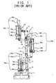
- As shown in Figure 1, a conventional two-legged walking robot includes a
foot member 11, acalf member 12, afemoral member 13, and ahip member 14, which are respectively connected byjoint parts ankle joint 15, aknee joint 16 and ahip joint 17. - In the leg assembly, each member is connected to an actuator to provide a four-bar linkage (e.g., quadric crank mechanism). The actuator makes a linear-sliding motion with a ball screw. The linear-sliding motion changes a rotation angle between links, thereby bending or stretching the leg assemblies of the walking robot.
- More particularly, to cause the bending and stretching operation in the
ankle joint 15, a middle part of afirst actuator 30a is pivotably connected to a middle part of thecalf member 12 by afirst link 21, and aslider 35a of thefirst actuator 30a is pivotably connected to a middle part of thefoot member 11. - To cause the bending and stretching operation in the
knee joint 16, a lower part of asecond actuator 30b is pivotably connected to an upper part of thefoot member 11 by asecond link 22, and a middle part of thesecond actuator 30b is pivotably connected to a middle part of thefemoral member 13 by athird link 23. - To cause the bending and stretching operation in the
hip joint 17, a lower part of athird actuator 30c is pivotably connected to an upper part of thefemoral member 13 by afourth link 24, and a middle part of thethird actuator 30c is pivotably connected to thehip member 14 by afifth link 25. - According to the above, the bending and stretching operations in the
joints actuators - The
actuator motor ball screw encoder motor guide rail ball screw slider guide rail ball screw - The
slider guide rail ball screw ball screw encoder motor motor - According to the above configuration, a walking operation of the conventional two-legged walking robot is achieved by the
actuators joints - However, in the conventional two-legged walking robot, the
joints - Accordingly, it is an aim of preferred embodiments of the present invention to provide a two-legged walking robot improved in a degree of freedom for a leg assembly.
- Additional features of the invention will be set forth in part in the description which follows and, in part, will be obvious form the description, or may be learned by practice of the invention.
- According to the present invention in a first aspect, there is provided a two-legged walking robot including a pair of foot members, a calf member provided above each of the foot members, a double-axis ankle joint provided between each of the respective foot member and the calf member to allow the foot member to rotate relative to the calf member in forward and backward directions and in right and left directions, and a pair of first actuators coupled to both of each of the respective foot member and the calf member to rotate the foot member relative to the calf member about the ankle joint in the forward, backward, right, and left directions; a femoral member provided above each of the calf members, a single-axis knee joint provided between each of the respective calf member and the femoral member, a second actuator coupled to both of each of the respective calf member and the femoral member to rotate the calf member relative to the femoral member about the knee joint in forward and backward directions, and a hip member provided above each of the femoral members; a double-axis hip joint provided between each of the respective femoral member and the hip member to allow the femoral member to rotate relative to the hip member in the forward, backward, right, and left directions, and a pair of third actuators coupled to both of each of the respective femoral member and the hip member to rotate the femoral member relative to the hip member about the hip joint in the forward, backward, right, and left directions.
- Suitably, each of the ankle joints include a first yoke incorporated with an upper part of the foot member, and a second yoke incorporated with a lower part of the calf member and coupled to the first yoke so as to rotate the foot member relative to the calf member.
- Suitably, the first yoke includes a first bracket incorporated with the upper part of the foot member, a pair of first supporters upwardly extended from front and rear end parts of the first bracket, and a first-axle to pass through the first supporters in the forward and backward directions, and the second yoke includes a second bracket incorporated with the lower part of the calf member, a pair of second supporters downwardly extended from left and right end parts of the second bracket, and a second-axle to pass through second supporters in left and right directions and incorporated with the first-axle.
- Suitably, each of the hip joints include a third yoke incorporated with an upper part of the femoral member, and a fourth yoke incorporated with a lower part of the hip member and coupled to the third yoke so as to rotate the femoral member relative to the hip member.
- Suitably, each of the hip joints are combined to the hip member rotatably about a vertical axis, and the two-legged walking robot further comprises a pair of fourth actuators provided in the hip member to rotate each of the respective femoral members relative to the hip member.
- Suitably, the robot further includes a first link provided between a lower part of the respective first actuators and the foot member so as to rotate the first actuators relative to the foot member, and a second link provided between an upper part of the respective first actuators and the calf member so as to rotate the first actuators relative to the calf member.
- Suitably, the robot further includes a third link provided between a lower part of the respective second actuator and the calf member so as to rotate the second actuator relative to the calf member, and a fourth link provided between an upper part of the respective second actuator and the femoral member so as to rotate the second actuator relative to the femoral member.
- Suitably, the robot further includes a fifth link provided between a lower part of the respective third actuators and the femoral member so as to rotate the third actuators relative to the femoral member, and a sixth link provided between an upper part of the respective third actuators and the hip member so as to rotate the third actuators relative to the hip member.
- Suitably, the second actuator is provided in front of the calf member, and an upper part of the third link is pivotably coupled to the lower part of the second actuator, and a hinge part on which the third link and the second actuator are pivoted is positioned above the knee joint, so that the calf member is rotated backward relative to the femoral member beyond a right angle.
- Suitably, the pair of third actuators is provided behind the femoral member, a lower part of the sixth link is rotatably coupled to the upper part of the third actuators, and a hinge part on which the sixth link and the third actuators are pivoted is positioned below the hip joint, so that the femoral member is rotated forward relative to the hip member beyond a right angle.
- Suitably, the robot further includes a shaft to protrude upwardly from the fourth yoke of the hip joint, and shaft passes through the hip member and is rotatably coupled to the hip member, and the fourth actuators are rotatably coupled to the shaft to rotate the shaft.
- Further features of the present invention are set out in the appended claims.
- The present invention will become apparent and more readily appreciated from the following description of the embodiments, by way of example only, taken in conjunction with the accompany drawings of which:
- Figure 1 is a side view of a conventional two-legged walking robot;
- Figure 2 is a perspective view of a two-legged walking robot, according to an embodiment of the present invention;
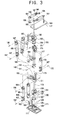
- Figure 3 is an exploded perspective view of the two-legged walking robot of Figure 2;
- Figure 4A is a side operation view of an ankle joint in the two-legged walking robot of Figure 2;
- Figure 4B is a rear operation view of the ankle joint in the two-legged walking robot of Figure 2;
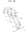
- Figures 5A and 5B are side operation views of a knee joint in the two-legged walking robot of Figure 2;
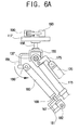
- Figures 6A and 6B are side operation views of a hip joint in the two-legged walking robot of Figure 2;
- Figure 6C is a rear operation view of the hip joint in the two-legged walking robot of Figure 2; and
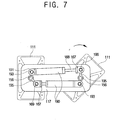
- Figure 7 is a plan operation view of a fourth actuator in the two-legged walking robot of Figure 2.
-
- Reference will now be made in detail to the embodiment of the present invention, an example of which are illustrated in the accompanying drawings, wherein like reference numerals refer to like elements throughout. Hereinafter, left, right, forward and backward directions are defined with reference to a forward movement of a walking robot.
- As shown in Figures 2 and 3, a two-legged
walking robot 100 according to the present invention includes a pair offoot members 111 to step on a ground like a human foot, a pair ofcalf members 113 respectively provided above thefoot members 111, a pair offemoral members 115 respectively provided above thecalf members 113, ahip member 117 provided above thefemoral members 115 like a human hip, and a double-axis ankle joint 120 (universal joint) provided between thefoot member 111 and thecalf member 113. The robot also includes a pair offirst actuators 160 coupled to both thefoot member 111 and thecalf member 113 to rotate thefoot member 111 relative to thecalf member 113 about theankle joint 120 in forward and backward directions and in right and left directions. The robot includes a single-axis knee joint 140 provided between thecalf member 113 and thefemoral member 115, asecond actuator 170 coupled to both thecalf member 113 and thefemoral member 115 to rotate thecalf member 113 relative to thefemoral member 115 about theknee joint 140 in the forward and backward directions, and a double-axis hip joint 150 (universal joint) provided between thefemoral member 115 and thehip member 117. The robot includes a pair ofthird actuators 180 coupled to both thefemoral member 115 and thehip member 117 to rotate thefemoral member 115 relative to thehip member 117 about thehip joint 150 in the forward, backward, right, and left directions, and a pair offourth actuators 190 provided on thehip member 117 to rotate thefemoral member 150 relative to thehip member 117 about a vertical axis. - Hereinafter, to avoid repetitive description, a mechanism of one side of the two-legged
walking robot 100 will be described due to its symmetrical configuration. - The
foot member 111, thecalf member 113, thefemoral member 115 and thehip member 117 function like bones of a human leg and are made of a rigid material strong enough to support an upper body (not shown) to be placed on thehip member 117. - The
ankle joint 120 includes afirst yoke 121 incorporated with an upper part of thefoot member 111, asecond yoke 131 incorporated with a lower part of thecalf member 113 and coupled to thefirst yoke 121 so as to rotate thefoot member 111 relative to thecalf member 113, and a double-axis trunnion 130 to combine thefirst yoke 121 with thesecond yoke 131 to allow relative rotation between thefirst yoke 121 and thesecond yoke 131 in forward and backward directions and in right and left directions. - The
first yoke 121 includes afirst bracket 123 incorporated with the upper part of thefoot member 111, and a pair offirst supporters 125 upwardly extended from front and rear end parts of thefirst bracket 123. Thefirst supporters 125 are each provided withholes 128 to which opposite ends of a first-axle 127 of thetrunnion 130 are rotatably inserted, thereby allowing thefirst yoke 121 to be rotated relative to thesecond yoke 131 in the left and right directions. - The
second yoke 131 includes asecond bracket 133 incorporated with the lower part of thecalf member 113, and a pair ofsecond supporters 135 downwardly extended from left and right end parts of thesecond bracket 133. Thesecond supporters 135 are each provided with theholes 128 to which opposite end parts of a second-axle 137 incorporated with the first-axle 127 are rotatably inserted, thereby allowing thefirst yoke 121 to be pivoted relative to thesecond yoke 131 in the forward and backward directions. - The
trunnion 130 includes the first-axle 127 inserted in theholes 128 of thefirst supporters 125 in the forward and backward directions, and thesecond axle 137 crosswise incorporated with the first-axle 127 and inserted in theholes 128 of thesecond supporters 135 in the left and right directions. - Thus, the
foot member 111 incorporated with thefirst yoke 121 is rotated relative to thecalf member 113 incorporated with thesecond yoke 131 about the first-axle 127 and the second-axle 137 in the forward, backward, right, and left directions. - The
knee joint 140 includes aknee hinge part 143 to connect an upper part of thecalf member 113 with a lower part of thefemoral member 115 to pivot thecalf member 113 relative to thefemoral member 115, and agudgeon pin 141 inserted in theknee hinge part 143. Thus, thecalf member 113 is rotated relative to thefemoral member 115 about theknee joint 140 in the forward and backward directions. - The
hip joint 150 includes athird yoke 151 incorporated with an upper part of thefemoral member 115, and afourth yoke 155 incorporated with a lower part of thehip member 117 and coupled to thethird yoke 151 so as to rotate thefemoral member 115 relative to thehip member 117. Thethird yoke 151 and thefourth yoke 155 are coupled to each other by a double-axis trunnion 130 like the first andsecond yokes ankle joint 120, and therefore a detailed description thereof will be omitted to avoid repetitive descriptions. - Thus, the
femoral member 115 is rotated relative to thehip member 117 about thehip joint 150 in the forward, backward, right, and left directions. - Further, there is provided a
shaft 156 to protrude upwardly from thefourth yoke 155 of thehip joint 150. Theshaft 156 passes through thehip member 117, thereby allowing theshaft 156 to rotate relative to thehip member 117 about a vertical axis. - The pair of
first actuators 160 is coupled to both thefoot member 111 and thecalf member 113 behind the ankle joint 120 and is employed to rotate thefoot member 111 relative to thecalf member 113 about the ankle joint 120 in the forward, backward, right, and left directions. Thefoot member 111 and thecalf member 113 are provided with afirst link 161 and asecond link 165, respectively, to be coupled to thefirst actuator 160. Eachactuator guide rod 168 provided in a lower part of each actuator 160, 170, 180 and 190 and engaged with the ball screw so as to be linearly guided by a guide member (not shown), a movingblock 167 attached to an end part of theguide rod 168, and a position sensor (not shown) connected to theguide rod 168 to sense a position of the movingblock 167 moving together with theguide rod 168. Here, sensed position data of the position sensor is transmitted to a controller (not shown), and the controller controls the motor according to the sensed position data, thereby moving the movingblock 167. - The
first link 161 has an "L"-shape, and a lower part of thefirst link 161 is rotatably coupled to thefirst yoke 121 incorporated with thefoot member 111. An upper part of thefirst link 161 and the movingblock 167 of thefirst actuator 160 are rotatably combined to each other with afirst hinge pin 162, thereby providing afirst hinge part 163. - The
second link 165 has a first part incorporated with thecalf member 113. A second part of thesecond link 165 and an upper part of thefirst actuator 160 are rotatably combined to each other with asecond hinge pin 166, thereby providing asecond hinge part 164. - With the above configuration, herein below, an operation of the ankle joint 120 and the
first actuator 160 will be described with reference to Figures 4A and 4B. - As shown in Figure 4A, when both moving
blocks 167 of the pair offirst actuators 160 move upward, thefoot member 111 rotates backward relative to thecalf member 113. Oppositely, when both movingblocks 167 of the pair offirst actuators 160 move downward, thefoot member 111 rotates forward relative to thecalf member 113. - As shown in Figure 4B, when the moving
block 167 of the leftfirst actuator 160 moves downward and the movingblock 167 of the rightfirst actuator 160 moves upward, thefoot member 111 rotates rightward relative to thecalf member 113. Oppositely, when the movingblock 167 of the leftfirst actuator 160 moves upward and the movingblock 167 of the rightfirst actuator 160 moves downward, thefoot member 111 rotates leftward relative to thecalf member 113. - Thus, the two-
legged walking robot 100 according to this embodiment of the present invention includes the ankle joint 120 having the double-axis trunnion 130 like a universal joint, and the pair offirst actuators 160 provided behind the ankle joint 120, so that the ankle joint 120 allows thefoot member 111 to be rotated relative to thefoot member 113 in the forward, backward, right, and left directions like a human foot. - The
second actuator 170 is coupled to both thecalf member 113 and thefemoral member 115 in front of thefemoral member 115 and is employed to rotate thecalf member 113 relative to thefemoral member 115 about the knee joint 140 in the forward and backward directions. Thecalf member 113 and thefemoral member 115 are provided with athird link 171 and afourth link 175 to be coupled to thesecond actuator 170, respectively. - The
third link 171 has an "L"-shape, and a lower part of thethird link 171 is incorporated with thecalf member 113. An upper part of thethird link 171 and the movingblock 167 of thesecond actuator 170 are rotatably combined to each other with athird hinge pin 172, thereby providing athird hinge part 173. Here, thethird hinge part 173 is positioned above the knee joint 140 in front of the knee joint 140, so that thecalf member 113 is rotated backward relative to thefemoral member 115 beyond a right angle. - The
fourth link 175 has a first part incorporated with thefemoral member 115, and a second part of thefourth link 175 and an upper part of thesecond actuator 170 are rotatably combined to each other with a fourth hinge pin 176, thereby providing afourth hinge part 177. - With the above configuration, hereinbelow, an operation of the knee joint 140 and the
second actuator 170 will be described with reference to Figures 5A and 5B. - As shown in Figure 5A, when the moving
block 167 of thesecond actuator 170 moves downward, thecalf member 113 rotates backward relative to thefemoral member 115. Oppositely, when the movingblock 167 of thesecond actuator 170 moves upward, thecalf member 113 rotates forward relative to thefemoral member 115. Further, as shown in Figure 5B, thecalf member 113 is rotated backward relative to thefemoral member 115 beyond the right angle because thethird hinge part 173 is positioned above the knee joint 140 in front of theknee joint 140. - Thus, the two-
legged walking robot 100 according to this embodiment of the present invention includes thesecond actuator 170 in front of the knee joint 140, and thethird hinge part 173 on which thesecond actuator 170 and thethird link 171 are pivotably positioned above the knee joint 140, so that the knee joint 140 allows thecalf member 113 to be rotated backward relative to thefemoral member 115 beyond the right angle like a human knee. - The pair of
third actuators 180 is coupled to both thefemoral member 115 and thehip member 117 behind thefemoral member 115 and is employed to rotate thefemoral member 115 relative to thehip member 117 about the hip joint 150 in the forward, backward, right, and left directions. Thefemoral member 115 and thehip member 117 are provided with afifth link 181 and asixth link 185 to be coupled to thethird actuators 180, respectively. - The
fifth link 181 has a first part incorporated with thefemoral member 115, and a second part of thefifth link 165 and the movingblock 167 of thethird actuators 180 are rotatably combined to each other with afifth hinge pin 182, thereby providing afifth hinge part 183. - The
sixth link 185 has an "L"-shape, and an upper part of thesixth link 185 is incorporated with thefourth yoke 155 incorporated with thehip member 117. A lower branch part of thesixth link 185 and the upper part of thethird actuators 180 are rotatably combined to each other with asixth hinge pin 186, thereby providing asixth hinge part 187 to allow thefemoral member 115 to rotate relative to thehip member 117 in the forward and backward directions. Further, an end part of the lower branch part of thesixth link 185 is rotatable relative to thesixth hinge part 187, so that thefemoral member 115 is rotated relative to thehip member 117 in the left and right directions. - Here, the
sixth hinge part 187 on which thethird actuators 180 and thesixth link 185 are pivoted is positioned below thehip joint 150, so that thefemoral member 115 is rotated forward relative to thehip member 117 beyond a right angle. - With the above configuration, hereinbelow, an operation of the
hip joint 150 and thethird actuators 180 will be described with reference to Figures 6A through 6C. - As shown in Figure 6A, when both moving
blocks 167 of the pair ofthird actuators 180 move downward, thefemoral member 115 rotates forward relative to thehip member 117. Oppositely, when both movingblocks 167 of the pair ofthird actuators 180 move upward, thefemoral member 115 rotates backward relative to thehip member 117. As shown in Figure 6C, when the movingblock 167 of the leftthird actuator 180 moves downward and the movingblock 167 of the rightthird actuator 180 moves upward, thefemoral member 115 rotates rightward relative to thehip member 117. As shown in Figure 6B, thefemoral member 115 is rotated forward relative to thehip member 117 beyond the right angle because thesixth hinge part 187 is positioned above thehip joint 150 behind thehip joint 150. - Thus, the two-
legged walking robot 100 according to the present invention includes thehip joint 150 having the double-axis trunnion 130 like a universal joint, and the pair ofthird actuators 180 provided behind thefemoral member 115, so that thehip joint 150 allows thefemoral member 115 to be rotated relative to thehip member 117 in the forward, backward, right, and left directions like a human hip. Further, thehip joint 150 allows thefemoral member 115 to be rotated forward relative to thehip member 117 beyond the right angle like the human hip because thesixth hinge part 187 is positioned above the hip joint 150 in front of thehip joint 150. - The pair of
fourth actuators 190 is provided on thehip member 117, and is employed to rotate the pair ofhip joints 150 about a vertical axis. Eachfourth actuator 190 has a first part rotatably coupled to aprojection 193 provided on thehip member 117 to provide aseventh hinge part 191, and a second part pivotably coupled to theshaft 156 by aseventh link 195. Theshaft 156 protrudes from thefourth yoke 155 and passes through thehip member 117. - The
seventh link 195 has a first part incorporated with theshaft 156, and a second part rotatably coupled to the second part of thefourth actuator 190 to provide aneighth hinge part 196. - According to the above configuration, as shown in Figure 7, when an operation of the
fourth actuator 190 causes rotation of theseventh link 195, theshaft 156 incorporated with theseventh link 195 rotates about the vertical axis, so that the hip joint 150 incorporated with theshaft 156, thefemoral member 115, thecalf member 113 and thefoot member 111 are all rotated about the vertical axis. - Thus, the two-
legged walking robot 100 according to this embodiment of the present invention includes thefourth actuator 190 to rotate thehip joint 150, thefemoral member 115, thecalf member 113 and thefoot member 111 about the vertical axis of theshaft 156, thereby operating like the human hip. - As described above, the two-legged walking robot according to an embodiment of the present invention includes the ankle and hip joints using the universal joints, and the pairs of first and third actuators. Accordingly, the hinge part on which the third actuators and the sixth link are pivoted is positioned below the hip joint, so that the ankle and hip joints operate like the human ankle and hip.
- Further, the two-legged walking robot according to a preferred embodiment of the present invention includes the second actuator linked with the knee joint. Accordingly, the hinge part on which the second actuator and the third link are pivoted is positioned above the knee joint, so that the knee joint operates like the human knee.
- Further, the two-legged walking robot according to a preferred embodiment of the present invention includes the fourth actuators to rotate the hip joint, the femoral member, the calf member and the foot member about the vertical axis, so that the hip joint operates like the human hip.
- As described above, a preferred embodiment of the present invention provides a two-legged walking robot to operate like the human ankle, knee and hip.
- Although an embodiment of the present invention has been shown and described, it will be appreciated by those skilled in the art that changes may be made in the embodiment without departing from the principles and spirit of the invention, the scope of which is defined in the appended claims and their equivalents.
- Attention is directed to all papers and documents which are filed concurrently with or previous to this specification in connection with this application and which are open to public inspection with this specification, and the contents of all such papers and documents are incorporated herein by reference.
- All of the features disclosed in this specification (including any accompanying claims, abstract and drawings), and/or all of the steps of any method or process so disclosed, may be combined in any combination, except combinations where at least some of such features and/or steps are mutually exclusive.
- Each feature disclosed in this specification (including any accompanying claims, abstract and drawings) may be replaced by alternative features serving the same, equivalent or similar purpose, unless expressly stated otherwise. Thus, unless expressly stated otherwise, each feature disclosed is one example only of a generic series of equivalent or similar features.
- The invention is not restricted to the details of the foregoing embodiment(s). The invention extends to any novel one, or any novel combination, of the features disclosed in this specification (including any accompanying claims, abstract and drawings), or to any novel one, or any novel combination, of the steps of any method or process so disclosed.
Claims (39)
- A two-legged walking robot (100), comprising:a pair of foot members (111);a calf member (113) provided above each of the foot members (111);a double-axis ankle joint (120) provided between each of the respective foot member (111) and the calf member (113) to allow the foot member (111) to rotate relative to the calf member (113) in forward and backward directions and in right and left directions;a pair of first actuators (160) coupled to both of each of the respective foot member (111) and the calf member (113) to rotate the foot member (111) relative to the calf member (113) about the ankle joint (120) in the forward, backward, right, and left directions;a femoral member (115) provided above each of the calf members (113);a single-axis knee joint (140) provided between each of the respective calf member (113) and the femoral member (115) ;a second actuator (170) coupled to both of each of the respective calf member (113) and the femoral member (115) to rotate the calf member (113) relative to the femoral member (115) about the knee joint (140) in forward and backward directions;a hip member (117) provided above each of the femoral members (115);a double-axis hip joint (150) provided between each of the respective femoral member (115) and the hip member (117) to allow the femoral member (115) to rotate relative to the hip member (117) in the forward, backward, right, and left directions; anda pair of third actuators (180) coupled to both of each of the respective femoral member (115) and the hip member (117) to rotate the femoral member (115) relative to the hip member (117) about the hip joint (150) in the forward, backward, right, and left directions.
- The robot according to claim 1, wherein each of the ankle joints (120) comprise:a first yoke (121) incorporated with an upper part of the foot member (111); anda second yoke (131) incorporated with a lower part of the calf member (113) and coupled to the first yoke (121) so as to rotate the foot member (111) relative to the calf member (113).
- The robot according to claim 2, wherein:the first yoke (121) comprises a first bracket (123) incorporated with the upper part of the foot member (111), a pair of first supporters (125) upwardly extended from front and rear end parts of the first bracket (123), and a first-axle (127) to pass through the first supporters (125) in the forward and backward directions, andthe second yoke (131) comprises a second bracket (133) incorporated with the lower part of the calf member (113), a pair of second supporters (135) downwardly extended from left and right end parts of the second bracket (133), and a second-axle (137) to pass through second supporters (135) in left and right directions and crosswise incorporated with the first-axle (127).
- The robot according to claim 3, wherein each of the hip joints (150) comprise:a third yoke (151) incorporated with an upper part of the femoral member (115); anda fourth yoke (155) incorporated with a lower part of the hip member (117) and coupled to the third yoke (151) so as to rotate the femoral member (115) relative to the hip member (117).
- The robot according to claim 4, wherein each of the hip joints (150) are combined to the hip member (117) rotatably about a vertical axis, and the two-legged walking robot further comprises:a pair of fourth actuators (190) provided in the hip member (117) to rotate each of the respective femoral members (115) relative to the hip member (117).
- The robot according to any preceding claim, further comprising:a first link (161) provided between a lower part of the respective first actuators (160) and the foot member (111) so as to rotate the first actuators (160) relative to the foot member (111); anda second link (165) provided between an upper part of the respective first actuators (160) and the calf member (113) so as to rotate the first actuators (160) relative to the calf member (113).
- The robot according to claim 6, further comprising:a third link (171) provided between a lower part of the respective second actuator (170) and the calf member (113) so as to rotate the second actuator (170) relative to the calf member (113); anda fourth link (175) provided between an upper part of the respective second actuator (170) and the femoral member (115) so as to rotate the second actuator (170) relative to the femoral member (115).
- The robot according to claim 7, further comprising:a fifth link (181) provided between a lower part of the respective third actuators (180) and the femoral member (115) so as to rotate the third actuators (180) relative to the femoral member (115); anda sixth link (185) provided between an upper part of the respective third actuators (180) and the hip member (117) so as to rotate the third actuators (180) relative to the hip member (117).
- The robot according to claim 7, wherein:the second actuator (170) is provided in front of the calf member (113),an upper part of the third link (171) is pivotably coupled to the lower part of the second actuator (170),and a hinge part (173) on which the third link and the second actuator (170) are pivoted is positioned above the knee joint (140), so that the calf member (113) is rotated backward relative to the femoral member (115) beyond a right angle.
- The robot according to claim 8, wherein:the pair of third actuators (180) is provided behind the femoral member (115),a lower part of the sixth link (185) is rotatably coupled to the upper part of the third actuators (180),and a hinge part (183) on which the sixth link (185) and the third actuators (180) are pivoted is positioned below the hip joint (150), so that the femoral member (115) is rotated forward relative to the hip member (117) beyond a right angle.
- The robot according to claim 5, further comprising:a first link (161) provided between a lower part of the respective first actuators (160) and the foot member (111) so as to rotate the first actuators (160) relative to the foot member (111); anda second link (165) provided between an upper part of the respective first actuators (160) and the calf member (113) so as to rotate the first actuators (160) relative to the calf member (113).
- The robot according to claim 11, further comprising:a third link (171) provided between a lower part of the respective second actuator (170) and the calf member (113) so as to rotate the second actuator (170) relative to the calf member (113); anda fourth link (175) provided between an upper part of the respective second actuator (170) and the femoral member (115) so as to rotate the second actuator (170) relative to the femoral member (115).
- The robot according to claim 12, further comprising:a fifth link (181) provided between a lower part of the respective third actuators (180) and the femoral member (115) so as to rotate the third actuators (180) relative to the femoral member (115); anda sixth link (185) provided between an upper part of the respective third actuators (180) and the hip member (117) so as to rotate the third actuators (180) relative to the hip member (117).
- The robot according to claim 12, wherein:the second actuator (170) is provided in front of the calf member (113),an upper part of the third link (171) is pivotably coupled to the lower part of the second actuator (170), and a hinge part (173) on which the third link (171) and the second actuator (170) are pivoted is positioned above the knee joint (140), so that the calf member (113) is rotated backward relative to the femoral member (115) beyond a right angle.
- The robot according to claim 13, wherein:the pair of third actuators (180) is provided behind the femoral member (115),a lower part of the sixth link (185) is rotatably coupled to the upper part of the third actuators (180); anda hinge part (183) on which the sixth link (185) and the third actuators (180) are pivoted is positioned below the hip joint (150), so that the femoral member (115) is rotated forward relative to the hip member (117) beyond a right angle.
- The robot according to claim 5, further comprising:wherein the shaft (156) passes through the hip member (117) and is rotatably coupled to the hip member (117); anda shaft (156) to protrude upwardly from the fourth yoke (155) of the hip joint (150),
the fourth actuators (190) are rotatably coupled to the shaft (156) to rotate the shaft (156). - The robot according to any preceding claim, wherein the foot members (111), the calf members (113), the femoral members (115) and the hip member (117) are made of a rigid material to support a body to be placed on the hip member (117).
- The robot according to claim 3, wherein each of the ankle joints (120) further comprise:a double-axis trunnion (130) to combine the first yoke (121) with the second yoke (131) to allow relative rotation between the first yoke (121) and the second yoke (131) in the forward, backward, right and left directions.
- The robot according to claim 18, wherein the first supporters (125) are provided with holes (128) to which opposite ends the first axle (127) are rotatably inserted, allowing the first yoke (121) to be rotated relative to the second yoke (131) in the left and right directions.
- The robot according to claim 19, wherein the second supporters (135) are provided with holes (128) to which opposite ends of the second axle (137) are rotatably inserted, allowing the first yoke (121) to be pivoted relative to the second yoke (131) in the forward and backward directions.
- The robot according to any preceding claim, wherein each of the single-axis knee joints (140) comprise:a knee hinge part (143) to connect a part of the calf member (113) with a part of the femoral member (115) to pivot the calf member (113) relative to the femoral member (115); anda gudgeon pin (141) to insert into the knee hinge part (143), allowing the calf member (113) to rotate relative to the femoral member (115) about the knee joint (140) in the forward and backward directions.
- The robot according to claim 21, wherein each of the single-axis knee joints (140) further comprise:a double-axis trunnion (130) to combine the third yoke (151) with the fourth yoke (155) to allow relative rotation between the third yoke (151) and the fourth yoke (155) in the forward, backward, right and left directions.
- The robot according to claim 11, wherein a part of the first link (161) is rotatably coupled to the first yoke (121) incorporated with the foot member (111), and the second link (165) comprises a first part incorporated with the calf member (113).
- The robot according to claim 23, further comprising:a first hinge pin (162) to rotatably combine the first link (21) and a moving block (167) of the first actuators (160), providing a first hinge part (163); anda second hinge pin (166) to rotatably combine a second part of the second link (22) and a part of the first actuators (160), providing a second hinge part (164).
- The robot according to claim 12, wherein a part of the third link (171) is incorporated with the calf member (113), and the fourth link (175) comprises a first part incorporated with the femoral member (115).
- The robot according to claim 25, further comprising:a third hinge pin (172) to rotatably combine a part of the third link (171) and a moving block (167) of the second actuator (170), providing a third hinge part (173); anda fourth hinge pin (176) to rotatably combine a second part of the fourth link (175) and a part of the second actuator (170), providing a fourth hinge part (177).
- The robot according to claim 13, wherein a first part of the fifth link (181) is incorporated with the femoral member (115), and a part of the sixth link (185) is incorporated with the fourth yoke (155) incorporated with the hip member (117).
- The robot according to claim 27, further comprising:a fifth hinge pin (182) to rotatably combine a second part of the fifth link (181) and a moving block (167) of the third actuators (180), providing a fifth hinge part (183); anda sixth hinge pin (186) to rotatably combine a branched part of the sixth link (185) and a part of the third actuators (180), providing a sixth hinge part (187).
- The robot according to claim 16, wherein the fourth actuators (190) comprise a first part to rotatably couple to a projection (193) provided on the hip member (117), providing a seventh hinge part (191), and a second part to pivotably couple to the shaft (156).
- The robot according to claim 29, further comprising:a seventh link (195) having a first part incorporated with the shaft (156), and a second part to rotatably couple to the second part of the fourth actuators (190), providing an eighth hinge part (196).
- The robot according to claim 30, wherein the fourth actuators (190) rotate the seventh link (195) to rotate the shaft (156) incorporated with the seventh link (195) about a vertical axis, rotating the hip joints (150), the femoral members (115), the calf members (113), and the foot members (111) about the vertical axis.
- A two-legged walking robot, comprising:a pair of foot members (111);a calf member (113) provided above each of the foot members (111);a double-axis ankle joint (120) provided between each of the respective foot member (111) and the calf member (113) to allow the foot member (111) to rotate relative to the calf member (113) in forward and backward directions and in right and left directions;a pair of first actuators (160) coupled to both of each of the respective foot member (111) and the calf member (113) to rotate the foot member (111) relative to the calf member (113) about the ankle joint in the forward, backward, right, and left directions;a femoral member (115) provided above each of the calf members (113);a single-axis knee joint (140) provided between each of the respective calf member (113) and the femoral member (115);a second actuator (170) coupled to both of each of the respective calf member (113) and the femoral member (115) to rotate the calf member (113) relative to the femoral member (115) about the knee joint (140) in forward and backward directions;a hip member (117) provided above each of the femoral members (115);a double-axis hip joint (150) provided between each of the respective femoral member (115) and the hip member (117) to allow the femoral member (115) to rotate relative to the hip member (117) in the forward, backward, right, and left directions;a pair of third actuators (180) coupled to both of each of the respective femoral member (115) and the hip member (117) to rotate the femoral member (115) relative to the hip member (117) about the hip joint (150) in the forward, backward, right, and left directions; anda pair of fourth actuators (190) provided on the hip member (117) to rotate each of the respective femoral members (115) relative to the hip member (117).
- The robot according to claim 32, wherein each of the first, second, third, and fourth actuators (160, 170, 180 and 190) comprise:a motor;a ball screw to be rotated by the motor;a guide rod (168) provided in a part of each of the actuators (160, 170, 180, 190) to engage with the ball screw to be linearly guided by a guide member;a moving block (167) to attach to an end part of the guide rod (168); anda position sensor connected to the guide rod (168) to sense a position of the moving block (167) which moves together with the guide rod (168).
- The robot according to claim 33, wherein:when the moving block (167) of the first actuators (160) moves upward, the foot member (111) rotates backward relative to the calf member (113), andwhen the moving block (167) of the first actuators (160) moves downward, the foot member (111) rotates forward relative to the calf member (113).
- The robot according to claim 33, wherein:when the moving block (167) of a left first actuator of the first actuators (160) moves downward and the moving block (167) of a right first actuator of the first actuators (160) moves upward, the foot member (111) rotates rightward relative to the calf member (113), andwhen the moving block (167) of the left first actuator (160) moves upward and the moving block (167) of the right first actuator (160) moves downward, the foot member (111) rotates leftward relative to the calf member (113).
- The robot according to claim 33, wherein:when the moving block (167) of the second actuator (170) moves downward, the calf member (113) rotates backward relative to the femoral member (115), andwhen the moving block (167) of the second actuator (170) moves upward, the calf member (113) rotates forward relative to the femoral member (115).
- The robot according to claim 33, wherein:when the moving block (167) of the third actuators (180) moves downward, the femoral member (115) rotates forward relative to the hip member (117), andwhen the moving block (167) of the third actuators (180) moves upward, the femoral member (115) rotates backward relative to the hip member (117).
- The robot according to claim 33, wherein;
when the moving block (167) of a left third actuator of the third actuators (180) moves downward and the moving block (167) of a right third actuator of the third actuators (180) moves upward, the femoral member (115) rotates rightward relative to the hip member (117). - A two-legged walking robot (100), comprising:a pair of foot members (111);a calf member (113) provided above each of the foot members (111);a double-axis ankle joint (120) provided between each of the respective foot member (111) and the calf member (113) to allow the foot member (111) to rotate relative to the calf member (113) in forward and backward directions and in right and left directions;a femoral member (115) provided above each of the calf members (113);a single-axis knee joint (140) provided between each of the respective calf member (113) and the femoral member (115) ;a hip member (117) provided above each of the femoral members (115); anda double-axis hip joint (150) provided between each of the respective femoral member (115) and the hip member (117) to allow the femoral member (115) to rotate relative to the hip member (117) in the forward, backward, right, and left directions.
Applications Claiming Priority (2)
| Application Number | Priority Date | Filing Date | Title |
|---|---|---|---|
| KR1020020082459A KR100541433B1 (en) | 2002-12-23 | 2002-12-23 | 2-footed walking robot |
| KR2002082459 | 2002-12-23 |
Publications (2)
| Publication Number | Publication Date |
|---|---|
| EP1433694A1 true EP1433694A1 (en) | 2004-06-30 |
| EP1433694B1 EP1433694B1 (en) | 2009-04-15 |
Family
ID=32464598
Family Applications (1)
| Application Number | Title | Priority Date | Filing Date |
|---|---|---|---|
| EP03022350A Expired - Lifetime EP1433694B1 (en) | 2002-12-23 | 2003-10-04 | Two-legged walking robot |
Country Status (6)
| Country | Link |
|---|---|
| US (1) | US7099743B2 (en) |
| EP (1) | EP1433694B1 (en) |
| JP (1) | JP2004202676A (en) |
| KR (1) | KR100541433B1 (en) |
| CN (1) | CN100500387C (en) |
| DE (1) | DE60327154D1 (en) |
Cited By (7)
| Publication number | Priority date | Publication date | Assignee | Title |
|---|---|---|---|---|
| WO2009135694A1 (en) * | 2008-05-09 | 2009-11-12 | Bia | Humanoid robot implementing a ball and socket joint |
| WO2009144320A1 (en) | 2008-05-29 | 2009-12-03 | Bia | Humanoid robot implementing a spherical hinge with coupled actuators |
| CN102582715A (en) * | 2012-03-15 | 2012-07-18 | 北京航空航天大学 | Mechanical foot device imitating cattle foot |
| CN106184464A (en) * | 2016-09-20 | 2016-12-07 | 上海逸动医学科技有限公司 | A kind of lower limb robot |
| ITUB20154008A1 (en) * | 2015-09-30 | 2017-03-30 | Marco Ceccarelli | Bipedal mechanism with parallel manipulators |
| WO2018112102A1 (en) * | 2016-12-15 | 2018-06-21 | Boston Dynamics, Inc. | Screw actuator for a legged robot |
| WO2020123833A1 (en) * | 2018-12-14 | 2020-06-18 | Moog Inc. | Humanoid lower body robot electro hydrostatic actuating ankle |
Families Citing this family (59)
| Publication number | Priority date | Publication date | Assignee | Title |
|---|---|---|---|---|
| WO2006129599A1 (en) * | 2005-05-31 | 2006-12-07 | Honda Motor Co., Ltd. | Control device and control program of walking assisting device |
| KR100624217B1 (en) * | 2005-06-27 | 2006-09-15 | (주)스맥 | 3D Complex Lung Link Device for Robot Joint Operation |
| KR100812818B1 (en) * | 2006-11-14 | 2008-03-12 | 한양대학교 산학협력단 | Leg of robot |
| EP2093025B1 (en) | 2007-10-23 | 2012-05-16 | Honda Motor Co., Ltd. | Two-legged walking robot |
| JP4911525B2 (en) * | 2007-10-23 | 2012-04-04 | 本田技研工業株式会社 | Biped robot |
| JP4911524B2 (en) * | 2007-10-23 | 2012-04-04 | 本田技研工業株式会社 | Biped robot |
| JP5468973B2 (en) * | 2010-04-22 | 2014-04-09 | 本田技研工業株式会社 | Legged mobile robot |
| JP5539040B2 (en) * | 2010-06-04 | 2014-07-02 | 本田技研工業株式会社 | Legged mobile robot |
| JP5729956B2 (en) * | 2010-09-29 | 2015-06-03 | Thk株式会社 | Limb body drive mechanism for mobile robot, and mobile robot using this limb body drive mechanism |
| KR101758702B1 (en) | 2011-05-24 | 2017-08-01 | 대우조선해양 주식회사 | Articulation apparatus for robot |
| JP5722747B2 (en) * | 2011-10-24 | 2015-05-27 | Thk株式会社 | Robot joint structure and robot incorporating this joint structure |
| JP5872846B2 (en) * | 2011-10-27 | 2016-03-01 | Thk株式会社 | Robot joint structure and humanoid robot incorporating this joint structure |
| JP5380675B2 (en) * | 2011-11-28 | 2014-01-08 | 防衛省技術研究本部長 | Actuator and jumping apparatus using the actuator |
| JP2013248698A (en) * | 2012-05-31 | 2013-12-12 | Thk Co Ltd | Lower limb structure for legged robot, and legged robot |
| JP5976401B2 (en) * | 2012-05-31 | 2016-08-23 | Thk株式会社 | Lower leg structure of legged robot and legged robot |
| CN103204190B (en) * | 2013-03-11 | 2015-06-24 | 大连理工大学 | Robot foot mechanism |
| CN103213131B (en) * | 2013-04-25 | 2014-12-24 | 戴文钟 | A Robotic Calf Structure Using Tie Rods to Simulate the Movement of Human Ankle |
| CN103241302B (en) * | 2013-05-29 | 2015-06-17 | 哈尔滨工业大学 | Pneumatic muscle driving bionic frog bouncing leg mechanism employing dual-joint mechanism form |
| JP6330287B2 (en) * | 2013-10-29 | 2018-05-30 | セイコーエプソン株式会社 | Robot, robot contact member |
| CN103738428A (en) * | 2013-12-27 | 2014-04-23 | 天津科技大学 | Human-like biped robot foot structure |
| JP6087329B2 (en) * | 2014-09-19 | 2017-03-01 | Thk株式会社 | Rotation drive mechanism in robot |
| CN104368151B (en) * | 2014-11-05 | 2016-10-05 | 深圳市普乐方文化科技股份有限公司 | 2DOF vivid platform |
| CN104444418B (en) * | 2014-11-07 | 2017-04-12 | 上海交通大学 | Eighteen-degree-of-freedom robot with bucket |
| JP6593991B2 (en) | 2014-12-25 | 2019-10-23 | 三菱重工業株式会社 | Mobile robot and tip tool |
| US10189519B2 (en) * | 2015-05-29 | 2019-01-29 | Oregon State University | Leg configuration for spring-mass legged locomotion |
| US9878751B1 (en) | 2015-10-08 | 2018-01-30 | Boston Dynamics, Inc. | Three-piston ankle mechanism of a legged robot and associated control system |
| CN106741277B (en) * | 2015-11-20 | 2020-10-30 | 沈阳新松机器人自动化股份有限公司 | Hybrid mechanical leg mechanism |
| EP3385571B1 (en) * | 2015-12-03 | 2024-03-13 | Kawasaki Jukogyo Kabushiki Kaisha | Two-degree-of-freedom drive mechanism |
| CN105480322B (en) * | 2015-12-17 | 2018-01-30 | 哈尔滨龙海特机器人科技有限公司 | One kind is used for legged type robot parallel leg structure of running at a high speed |
| CN105523098A (en) * | 2015-12-24 | 2016-04-27 | 哈尔滨工业大学 | Humanoid robot foot structure with adjustable rigidity |
| CN106114671B (en) * | 2016-06-23 | 2018-01-05 | 吉林大学 | A kind of passive vibration damping joint of stiffness function |
| CN106080831B (en) * | 2016-07-18 | 2017-12-26 | 吉林大学 | It is a kind of that there is the bionical completely passive double feet walking machine away from leg, talocalcaneal articulation |
| WO2018074101A1 (en) | 2016-10-20 | 2018-04-26 | 三菱電機株式会社 | Connection mechanism with three rotational degrees of freedom, robot, robot arm, and robot hand |
| CN106347517B (en) * | 2016-10-26 | 2018-06-22 | 河南工业大学 | Apery walking end service plate formula robot |
| CN106826759B (en) * | 2016-12-29 | 2024-02-09 | 深圳市优必选科技有限公司 | Foot structure and humanoid robot |
| CN107187512A (en) * | 2017-05-31 | 2017-09-22 | 地壳机器人科技有限公司 | Human-imitating double-foot walking robot |
| US10421510B2 (en) * | 2017-07-25 | 2019-09-24 | Sphero, Inc. | Three-legged robotic apparatus |
| CN107651037B (en) * | 2017-09-12 | 2019-04-12 | 北京航空航天大学 | A kind of legged type robot list leg device with hard and soft interchangeable joint |
| CN108082325A (en) * | 2017-12-21 | 2018-05-29 | 江苏集萃智能制造技术研究所有限公司 | A kind of double-foot robot lower limb mechanism of hydraulic-driven |
| CN107985439B (en) * | 2017-12-29 | 2023-12-05 | 北京钢铁侠科技有限公司 | Leg mechanism of humanoid robot |
| US12103160B2 (en) | 2018-04-25 | 2024-10-01 | Mitsubishi Electric Corporation | Rotation connecting mechanism, robot, robot arm, and robot hand |
| KR102067221B1 (en) * | 2018-06-08 | 2020-01-16 | 경북대학교 산학협력단 | An ankle structure for humanoid robot using two cylindrical linear series elastic actuator parallely |
| CN109987170B (en) * | 2019-04-08 | 2019-12-10 | 嘉兴学院 | A Cylinder-Based Humanoid Robot Lower Limb Device |
| CN110206840B (en) * | 2019-06-21 | 2020-07-14 | 重庆大学 | Femoral head-imitated damping structure and walking robot |
| CN110696941B (en) * | 2019-09-19 | 2024-04-09 | 浙江工业大学 | Redundant hybrid electrohydraulic hybrid driving anthropomorphic mechanical leg |
| CN111059431B (en) * | 2019-12-24 | 2022-11-15 | 燕山大学 | A two-degree-of-freedom parallel rotating platform with eccentric moment unloading device |
| CN110979505B (en) * | 2019-12-30 | 2021-06-04 | 深圳市优必选科技股份有限公司 | Hip joint structure and humanoid robot |
| CN111688839B (en) * | 2020-06-18 | 2021-03-19 | 敬科(深圳)机器人科技有限公司 | Shank mechanism and biped robot with same |
| CN111759677B (en) * | 2020-08-06 | 2022-03-29 | 马鞍山学院 | Leg joint rehabilitation series-parallel robot |
| CN112319209A (en) * | 2020-11-18 | 2021-02-05 | 内蒙古第一机械集团股份有限公司 | Driving device suitable for leg joint movement of robot |
| WO2022139033A1 (en) | 2020-12-24 | 2022-06-30 | 주식회사 다성기술 | Both-end support type actuator module |
| CN112937718B (en) * | 2021-02-05 | 2021-09-14 | 重庆工程职业技术学院 | Multi-foot robot |
| CN114750853A (en) * | 2022-05-17 | 2022-07-15 | 中国北方车辆研究所 | Passive type double-freedom-degree foot device of four-foot robot |
| CN115056884B (en) * | 2022-06-27 | 2023-10-17 | 北京工业大学 | Humanoid robot leg structure with differential joint decoupling and inertia upward movement characteristics |
| CN115415997B (en) * | 2022-08-16 | 2025-07-29 | 山东科技大学 | Antagonistic pneumatic muscle lower limb power exoskeleton |
| CN115946795B (en) * | 2023-03-10 | 2023-05-30 | 之江实验室 | Foot type robot with light leg characteristics |
| CN116080789B (en) * | 2023-04-07 | 2023-07-18 | 之江实验室 | A shock-absorbing and energy-storing foot structure and a biped robot |
| CN116729520B (en) * | 2023-08-11 | 2023-10-20 | 太原理工大学 | Bionic four-foot robot based on double-layer corrugated pipe pneumatic soft driver |
| KR102851934B1 (en) * | 2024-01-09 | 2025-08-28 | 한국생산기술연구원 | Leg joint robot |
Citations (5)
| Publication number | Priority date | Publication date | Assignee | Title |
|---|---|---|---|---|
| JPH05228856A (en) * | 1992-02-14 | 1993-09-07 | Fujitsu Ltd | Upright mechanism of artificial legs |
| JPH07285085A (en) * | 1994-04-14 | 1995-10-31 | Mitsubishi Heavy Ind Ltd | Walking leg device of robot |
| EP1083120A2 (en) * | 1999-09-07 | 2001-03-14 | Sony Corporation | Leg-movement-type robot and its hip joint device |
| FR2807959A1 (en) * | 2000-04-21 | 2001-10-26 | Centre Nat Rech Scient | Actuator, for articulated structures such as walking robots, uses screw and nut mechanism with attached sliding block having lateral movement and able to rotate |
| US20020079857A1 (en) * | 1999-04-05 | 2002-06-27 | Shinji Ishii | Robot, servo circuit, actuator, robot control method, and actuator driving method |
Family Cites Families (15)
| Publication number | Priority date | Publication date | Assignee | Title |
|---|---|---|---|---|
| US4556360A (en) * | 1982-09-01 | 1985-12-03 | Hoffmann George T | Robotic apparatus |
| DE3247866A1 (en) | 1982-12-23 | 1984-06-28 | Lothar Dipl.-Ing. 8000 München Bock | Robot peripheral device |
| JPS6297006A (en) | 1985-10-23 | 1987-05-06 | Hitachi Ltd | Articulated walking robot control device |
| JP3168066B2 (en) | 1992-04-28 | 2001-05-21 | 本田技研工業株式会社 | Control device for link type mobile robot |
| FR2697492B1 (en) * | 1992-11-05 | 1994-12-23 | Commissariat Energie Atomique | Walking robot foot. |
| AU1141595A (en) | 1995-01-27 | 1996-08-08 | Samuel N. Cubero Jr. | Space truss integrated-construction robot |
| FR2757925B1 (en) | 1996-12-27 | 1999-03-26 | Thomson Csf | MODULAR DEVICE FOR MOVING LOAD ACCORDING TO AT LEAST THREE DEGREES OF FREEDOM |
| KR100249419B1 (en) | 1998-01-15 | 2000-04-01 | 박호군 | The motion module of the multi-freedom degree using the human muscle characteristic |
| KR200168189Y1 (en) | 1999-08-02 | 2000-02-15 | 양창일 | Actuator with 3 degrees of freedom |
| JP3555107B2 (en) * | 1999-11-24 | 2004-08-18 | ソニー株式会社 | Legged mobile robot and operation control method for legged mobile robot |
| JP2001322079A (en) * | 2000-05-15 | 2001-11-20 | Sony Corp | Legged mobile robot and method of teaching its operation |
| KR100378713B1 (en) | 2000-06-01 | 2003-04-07 | 최형식 | Leg Joint Structure of Walking Robot |
| ES2166735B1 (en) | 2000-10-06 | 2003-10-16 | Consejo Superior Investigacion | ACTUATOR FOR THE LEGS OF A WALKING ROBOT. |
| TW499349B (en) * | 2000-11-17 | 2002-08-21 | Sony Corp | Legged mobile robot, leg structure of legged mobile robot, and mobile leg unit for legged mobile robot |
| WO2002045913A1 (en) * | 2000-11-20 | 2002-06-13 | Sony Corporation | Device and method for controlling operation of legged robot, and robot device |
-
2002
- 2002-12-23 KR KR1020020082459A patent/KR100541433B1/en not_active Expired - Fee Related
-
2003
- 2003-08-20 US US10/643,898 patent/US7099743B2/en not_active Expired - Fee Related
- 2003-09-27 CN CNB03160207XA patent/CN100500387C/en not_active Expired - Fee Related
- 2003-10-04 EP EP03022350A patent/EP1433694B1/en not_active Expired - Lifetime
- 2003-10-04 DE DE60327154T patent/DE60327154D1/en not_active Expired - Lifetime
- 2003-10-16 JP JP2003356858A patent/JP2004202676A/en active Pending
Patent Citations (5)
| Publication number | Priority date | Publication date | Assignee | Title |
|---|---|---|---|---|
| JPH05228856A (en) * | 1992-02-14 | 1993-09-07 | Fujitsu Ltd | Upright mechanism of artificial legs |
| JPH07285085A (en) * | 1994-04-14 | 1995-10-31 | Mitsubishi Heavy Ind Ltd | Walking leg device of robot |
| US20020079857A1 (en) * | 1999-04-05 | 2002-06-27 | Shinji Ishii | Robot, servo circuit, actuator, robot control method, and actuator driving method |
| EP1083120A2 (en) * | 1999-09-07 | 2001-03-14 | Sony Corporation | Leg-movement-type robot and its hip joint device |
| FR2807959A1 (en) * | 2000-04-21 | 2001-10-26 | Centre Nat Rech Scient | Actuator, for articulated structures such as walking robots, uses screw and nut mechanism with attached sliding block having lateral movement and able to rotate |
Non-Patent Citations (2)
| Title |
|---|
| PATENT ABSTRACTS OF JAPAN vol. 017, no. 675 (M - 1526) 13 December 1993 (1993-12-13) * |
| PATENT ABSTRACTS OF JAPAN vol. 1996, no. 02 29 February 1996 (1996-02-29) * |
Cited By (13)
| Publication number | Priority date | Publication date | Assignee | Title |
|---|---|---|---|---|
| WO2009135694A1 (en) * | 2008-05-09 | 2009-11-12 | Bia | Humanoid robot implementing a ball and socket joint |
| US9327785B2 (en) | 2008-05-09 | 2016-05-03 | Bia | Humanoid robot implementing a ball and socket joint |
| US8875594B2 (en) | 2008-05-29 | 2014-11-04 | Bia | Humanoid robot implementing a spherical hinge with coupled actuators |
| WO2009144320A1 (en) | 2008-05-29 | 2009-12-03 | Bia | Humanoid robot implementing a spherical hinge with coupled actuators |
| FR2931718A1 (en) * | 2008-05-29 | 2009-12-04 | Bia | HIP FOR HUMANOID ROBOT |
| CN102582715A (en) * | 2012-03-15 | 2012-07-18 | 北京航空航天大学 | Mechanical foot device imitating cattle foot |
| CN102582715B (en) * | 2012-03-15 | 2013-04-24 | 北京航空航天大学 | Mechanical foot device imitating cattle foot |
| ITUB20154008A1 (en) * | 2015-09-30 | 2017-03-30 | Marco Ceccarelli | Bipedal mechanism with parallel manipulators |
| CN106184464A (en) * | 2016-09-20 | 2016-12-07 | 上海逸动医学科技有限公司 | A kind of lower limb robot |
| WO2018112102A1 (en) * | 2016-12-15 | 2018-06-21 | Boston Dynamics, Inc. | Screw actuator for a legged robot |
| US11754155B2 (en) | 2016-12-15 | 2023-09-12 | Boston Dynamics, Inc. | Screw actuator for a legged robot |
| US12123481B2 (en) | 2016-12-15 | 2024-10-22 | Boston Dynamics, Inc. | Screw actuator for a legged robot |
| WO2020123833A1 (en) * | 2018-12-14 | 2020-06-18 | Moog Inc. | Humanoid lower body robot electro hydrostatic actuating ankle |
Also Published As
| Publication number | Publication date |
|---|---|
| CN1509848A (en) | 2004-07-07 |
| DE60327154D1 (en) | 2009-05-28 |
| US20040133307A1 (en) | 2004-07-08 |
| KR20040055967A (en) | 2004-06-30 |
| US7099743B2 (en) | 2006-08-29 |
| JP2004202676A (en) | 2004-07-22 |
| EP1433694B1 (en) | 2009-04-15 |
| KR100541433B1 (en) | 2006-01-11 |
| CN100500387C (en) | 2009-06-17 |
Similar Documents
| Publication | Publication Date | Title |
|---|---|---|
| EP1433694A1 (en) | Two-legged walking robot | |
| CN100381259C (en) | Walking type mobile robot | |
| US6248046B1 (en) | Elliptical motion exercise methods and apparatus | |
| KR101517058B1 (en) | Robot for assisting the muscular strength for hip joint and control method of the same | |
| US6080086A (en) | Elliptical motion exercise methods and apparatus | |
| US4840373A (en) | Four-bar rigid-drive variable resistance pectoral fly machine | |
| KR100888078B1 (en) | Joint structure of robot | |
| KR102311666B1 (en) | Multi link apparatus, lower-lomb exoskeleton robot using the same and methed for controlling the same | |
| KR100585421B1 (en) | Biped Humanoid Robot | |
| CA2419568C (en) | Parallel linkage and artificial joint device using the same | |
| KR102541802B1 (en) | A motion assist apparatus | |
| KR101496417B1 (en) | Robot for assisting the muscular strength for knee joint and control method of the same | |
| KR102339483B1 (en) | Transmission mechanism and robot using the same | |
| JP7149208B2 (en) | robot joint structure | |
| KR101712722B1 (en) | Robot for assisting the muscular strength for wearing lower body | |
| KR100520264B1 (en) | Double-arm shoulder joint mechanism of double-arm robot and both-legs hip joint mechanism of biped-walk robot | |
| KR102556920B1 (en) | Motion assistance apparatus | |
| KR100812818B1 (en) | Leg of robot | |
| CN114104142B (en) | Bionic mechanical leg | |
| KR102894922B1 (en) | Wearable ankle joint motion assist device | |
| KR102544209B1 (en) | Passive type wearable robot | |
| TWI887060B (en) | Intelligent serial elastic assistive device for linkage drive device of footed robot | |
| CN119929022B (en) | Robot lower limb and humanoid robot | |
| JP3678576B2 (en) | Horizontal / tilt adjustment device | |
| CN120664034A (en) | Mechanical leg assembly and robot |
Legal Events
| Date | Code | Title | Description |
|---|---|---|---|
| PUAI | Public reference made under article 153(3) epc to a published international application that has entered the european phase |
Free format text: ORIGINAL CODE: 0009012 |
|
| 17P | Request for examination filed |
Effective date: 20031004 |
|
| AK | Designated contracting states |
Kind code of ref document: A1 Designated state(s): AT BE BG CH CY CZ DE DK EE ES FI FR GB GR HU IE IT LI LU MC NL PT RO SE SI SK TR |
|
| AX | Request for extension of the european patent |
Extension state: AL LT LV MK |
|
| 17Q | First examination report despatched |
Effective date: 20040923 |
|
| AKX | Designation fees paid |
Designated state(s): DE FR GB |
|
| 17Q | First examination report despatched |
Effective date: 20040923 |
|
| GRAP | Despatch of communication of intention to grant a patent |
Free format text: ORIGINAL CODE: EPIDOSNIGR1 |
|
| GRAS | Grant fee paid |
Free format text: ORIGINAL CODE: EPIDOSNIGR3 |
|
| GRAA | (expected) grant |
Free format text: ORIGINAL CODE: 0009210 |
|
| AK | Designated contracting states |
Kind code of ref document: B1 Designated state(s): DE FR GB |
|
| REG | Reference to a national code |
Ref country code: GB Ref legal event code: FG4D |
|
| REF | Corresponds to: |
Ref document number: 60327154 Country of ref document: DE Date of ref document: 20090528 Kind code of ref document: P |
|
| PLBE | No opposition filed within time limit |
Free format text: ORIGINAL CODE: 0009261 |
|
| STAA | Information on the status of an ep patent application or granted ep patent |
Free format text: STATUS: NO OPPOSITION FILED WITHIN TIME LIMIT |
|
| 26N | No opposition filed |
Effective date: 20100118 |
|
| PGFP | Annual fee paid to national office [announced via postgrant information from national office to epo] |
Ref country code: GB Payment date: 20130926 Year of fee payment: 11 |
|
| PGFP | Annual fee paid to national office [announced via postgrant information from national office to epo] |
Ref country code: FR Payment date: 20130926 Year of fee payment: 11 Ref country code: DE Payment date: 20131003 Year of fee payment: 11 |
|
| REG | Reference to a national code |
Ref country code: DE Ref legal event code: R119 Ref document number: 60327154 Country of ref document: DE |
|
| GBPC | Gb: european patent ceased through non-payment of renewal fee |
Effective date: 20141004 |
|
| PG25 | Lapsed in a contracting state [announced via postgrant information from national office to epo] |
Ref country code: DE Free format text: LAPSE BECAUSE OF NON-PAYMENT OF DUE FEES Effective date: 20150501 Ref country code: GB Free format text: LAPSE BECAUSE OF NON-PAYMENT OF DUE FEES Effective date: 20141004 |
|
| REG | Reference to a national code |
Ref country code: FR Ref legal event code: ST Effective date: 20150630 |
|
| PG25 | Lapsed in a contracting state [announced via postgrant information from national office to epo] |
Ref country code: FR Free format text: LAPSE BECAUSE OF NON-PAYMENT OF DUE FEES Effective date: 20141031 |