JP5976401B2 - Lower leg structure of legged robot and legged robot - Google Patents
Lower leg structure of legged robot and legged robot Download PDFInfo
- Publication number
- JP5976401B2 JP5976401B2 JP2012124511A JP2012124511A JP5976401B2 JP 5976401 B2 JP5976401 B2 JP 5976401B2 JP 2012124511 A JP2012124511 A JP 2012124511A JP 2012124511 A JP2012124511 A JP 2012124511A JP 5976401 B2 JP5976401 B2 JP 5976401B2
- Authority
- JP
- Japan
- Prior art keywords
- thigh
- joint
- joint body
- hip joint
- pitch axis
- Prior art date
- Legal status (The legal status is an assumption and is not a legal conclusion. Google has not performed a legal analysis and makes no representation as to the accuracy of the status listed.)
- Active
Links
Images


Classifications
-
- B—PERFORMING OPERATIONS; TRANSPORTING
- B25—HAND TOOLS; PORTABLE POWER-DRIVEN TOOLS; MANIPULATORS
- B25J—MANIPULATORS; CHAMBERS PROVIDED WITH MANIPULATION DEVICES
- B25J9/00—Programme-controlled manipulators
- B25J9/10—Programme-controlled manipulators characterised by positioning means for manipulator elements
- B25J9/106—Programme-controlled manipulators characterised by positioning means for manipulator elements with articulated links
- B25J9/1065—Programme-controlled manipulators characterised by positioning means for manipulator elements with articulated links with parallelograms
-
- B—PERFORMING OPERATIONS; TRANSPORTING
- B62—LAND VEHICLES FOR TRAVELLING OTHERWISE THAN ON RAILS
- B62D—MOTOR VEHICLES; TRAILERS
- B62D57/00—Vehicles characterised by having other propulsion or other ground- engaging means than wheels or endless track, alone or in addition to wheels or endless track
- B62D57/02—Vehicles characterised by having other propulsion or other ground- engaging means than wheels or endless track, alone or in addition to wheels or endless track with ground-engaging propulsion means, e.g. walking members
- B62D57/032—Vehicles characterised by having other propulsion or other ground- engaging means than wheels or endless track, alone or in addition to wheels or endless track with ground-engaging propulsion means, e.g. walking members with alternately or sequentially lifted supporting base and legs; with alternately or sequentially lifted feet or skid
-
- Y—GENERAL TAGGING OF NEW TECHNOLOGICAL DEVELOPMENTS; GENERAL TAGGING OF CROSS-SECTIONAL TECHNOLOGIES SPANNING OVER SEVERAL SECTIONS OF THE IPC; TECHNICAL SUBJECTS COVERED BY FORMER USPC CROSS-REFERENCE ART COLLECTIONS [XRACs] AND DIGESTS
- Y10—TECHNICAL SUBJECTS COVERED BY FORMER USPC
- Y10S—TECHNICAL SUBJECTS COVERED BY FORMER USPC CROSS-REFERENCE ART COLLECTIONS [XRACs] AND DIGESTS
- Y10S901/00—Robots
- Y10S901/01—Mobile robot
-
- Y—GENERAL TAGGING OF NEW TECHNOLOGICAL DEVELOPMENTS; GENERAL TAGGING OF CROSS-SECTIONAL TECHNOLOGIES SPANNING OVER SEVERAL SECTIONS OF THE IPC; TECHNICAL SUBJECTS COVERED BY FORMER USPC CROSS-REFERENCE ART COLLECTIONS [XRACs] AND DIGESTS
- Y10—TECHNICAL SUBJECTS COVERED BY FORMER USPC
- Y10S—TECHNICAL SUBJECTS COVERED BY FORMER USPC CROSS-REFERENCE ART COLLECTIONS [XRACs] AND DIGESTS
- Y10S901/00—Robots
- Y10S901/27—Arm part
- Y10S901/28—Joint
-
- Y—GENERAL TAGGING OF NEW TECHNOLOGICAL DEVELOPMENTS; GENERAL TAGGING OF CROSS-SECTIONAL TECHNOLOGIES SPANNING OVER SEVERAL SECTIONS OF THE IPC; TECHNICAL SUBJECTS COVERED BY FORMER USPC CROSS-REFERENCE ART COLLECTIONS [XRACs] AND DIGESTS
- Y10—TECHNICAL SUBJECTS COVERED BY FORMER USPC
- Y10T—TECHNICAL SUBJECTS COVERED BY FORMER US CLASSIFICATION
- Y10T74/00—Machine element or mechanism
- Y10T74/20—Control lever and linkage systems
- Y10T74/20207—Multiple controlling elements for single controlled element
- Y10T74/20305—Robotic arm
- Y10T74/20329—Joint between elements
Description
本発明は、複数の脚部を有し、各々の脚部を揺動させながら歩行する脚式ロボットの下肢構造及び脚式ロボットに関する。 The present invention relates to a lower limb structure of a legged robot that has a plurality of legs and walks while swinging each leg, and a legged robot.
脚式ロボットは、複数の脚部を有し、各々の脚部を揺動させながら歩行する。人間のように二本足でバランスをとりながら歩く脚式ロボットは二足歩行ロボットと呼ばれる。動物のように四本足で歩行する脚式ロボットは四足歩行ロボットと呼ばれる。脚部の数は典型的には二本あるいは四本であるが、複数本であれば何本でもよい。 The legged robot has a plurality of legs and walks while swinging each leg. A legged robot that walks while balancing on two legs like a human is called a biped robot. A legged robot that walks on four legs like an animal is called a quadruped walking robot. The number of legs is typically two or four, but may be any number as long as there are a plurality of legs.
各脚部は、大腿部、下腿部、足平部に相当するリンクをロボットの胴部から股関節、膝関節、足首関節を介して順次連設して構成される。大腿部、下腿部、足平部に相当するリンクは、各関節に脚式ロボットの側方に伸びるピッチ軸の回りを回転可能に連結される。各関節には、リンクを回転させるモータ(アクチュエータ)が備えられる(例えば特許文献1参照)。モータが適切な駆動力を出力し、リンクの回転角度を制御することによって、脚式ロボットが脚部を胴部に対して前後に揺動させることができる。ここで、股関節は胴部と脚部を連結する関節を意味するものであり、四足歩行ロボットの胴部と前脚とを連結する関節も股関節に含まれる。また、モータは電気、ガソリン等のエネルギを機械的な動きに変換する装置であり、典型的には電動モータあるいはエンジンである。 Each leg part is configured by sequentially connecting links corresponding to the thigh part, the lower leg part, and the foot part from the trunk part of the robot through the hip joint, the knee joint, and the ankle joint. Links corresponding to the thigh, crus, and foot are connected to each joint so as to be rotatable about a pitch axis extending to the side of the legged robot. Each joint is provided with a motor (actuator) that rotates the link (see, for example, Patent Document 1). When the motor outputs an appropriate driving force and controls the rotation angle of the link, the legged robot can swing the leg portion back and forth with respect to the trunk portion. Here, the hip joint means a joint that connects the torso and the leg, and the joint that connects the torso and the front leg of the quadruped walking robot is also included in the hip joint. The motor is a device that converts energy such as electricity and gasoline into mechanical movement, and is typically an electric motor or an engine.
しかし、膝関節の屈伸運動を行うときには、股関節のモータの回転速度の2倍の速度で膝関節のモータを回転させる必要がある。このように、膝関節は他の関節に比べ、移動範囲と速度を大きくする必要があるので、大きなモータを必要とする。 However, when the knee joint bends and stretches, it is necessary to rotate the knee joint motor at twice the rotational speed of the hip joint motor. As described above, the knee joint needs to have a larger movement range and speed than other joints, and thus requires a large motor.
そこで、本発明は、膝関節を駆動させるアクチュエータの負荷を低減させることができる脚式ロボットの下肢構造及び脚式ロボットを提供することを目的とする。 Accordingly, an object of the present invention is to provide a leg-type robot leg structure and a leg-type robot that can reduce the load on an actuator that drives a knee joint.
上記課題を解決するために、本発明は、股関節本体と、大腿部と、前記股関節本体に対して前記大腿部を少なくともピッチ軸の回りに回転可能に連結する股関節ジョイントと、前記大腿部にピッチ軸の回りを回転可能に連結される膝関節本体と、一端部が前記股関節本体又は前記股関節ジョイントにピッチ軸の回りを回転可能に連結されると共に、他端部が前記膝関節本体にピッチ軸の回りを回転可能に連結される大腿部補助リンクと、前記大腿部補助リンクの前記一端部から前記他端部までの長さを伸縮させる膝関節アクチュエータと、を備え、前記股関節本体又は前記股関節ジョイント、前記大腿部、前記膝関節本体、及び前記大腿部補助リンクは、平行四辺形を形成する平行リンクを構成し、前記大腿部がピッチ軸の回りを回転するとき、前記平行リンクの作用により、前記股関節本体に対する前記膝関節本体の姿勢が一定に保たれ、そして、前記膝関節アクチュエータによって前記大腿部補助リンクを伸縮させることで、前記股関節本体に対して前記膝関節本体の姿勢を変化させる脚式ロボットの下肢構造である。 In order to solve the above problems, the present invention provides a hip joint body, a thigh, a hip joint that connects the thigh to the hip joint body so as to be rotatable at least about a pitch axis, and the thigh A knee joint main body connected to a part so as to be rotatable around a pitch axis, and one end part is connected to the hip joint body or the hip joint joint so as to be rotatable around a pitch axis, and the other end part is connected to the knee joint main body. A thigh auxiliary link that is coupled to be rotatable about a pitch axis, and a knee joint actuator that expands and contracts a length from the one end to the other end of the thigh auxiliary link , When the hip joint body or the hip joint joint, the thigh, the knee joint body, and the thigh auxiliary link constitute a parallel link forming a parallelogram, the thigh rotates around the pitch axis. By the action of the parallel link, the posture of the knee joint body with respect to the hip joint body is kept constant, and the thigh auxiliary link is expanded and contracted by the knee joint actuator, whereby the hip joint body is expanded and contracted. This is a leg structure of a legged robot that changes the posture of the knee joint body .
本発明によれば、大腿部がピッチ軸の回りを回転するとき、平行リンクの作用により、股関節本体に対する膝関節本体の姿勢が一定に保たれる。そして、膝関節アクチュエータによって大腿部補助リンクを伸縮させることで、股関節本体に対して一定に保たれた膝関節本体の姿勢を変化させることができる。このため、膝関節の屈伸運動を行うとき、膝関節にモータを設けた従来の脚式ロボットに比べて、大腿部に対する膝関節本体のピッチ軸回りの回転速度を半分にすることができる。したがって、膝関節アクチュエータの負荷を低減することができる。 According to the present invention, when the thigh rotates around the pitch axis, the posture of the knee joint body with respect to the hip joint body is kept constant by the action of the parallel link. Then, the posture of the knee joint body maintained constant with respect to the hip joint body can be changed by extending and contracting the thigh auxiliary link by the knee joint actuator. For this reason, when bending and extending the knee joint, the rotational speed around the pitch axis of the knee joint body relative to the thigh can be halved compared to a conventional legged robot provided with a motor at the knee joint. Therefore, the load on the knee joint actuator can be reduced.
以下添付図面に基づいて、本発明の一実施形態における脚式ロボットを説明する。図1(a)は本実施形態の脚式ロボットの全体構成を示す正面図、図1(b)は左側面図である。以下の説明において、脚式ロボットの進行方向をx軸方向、脚式ロボットからみて左右方向をy軸方向、脚式ロボットの上下方向をz軸向とし、x軸をロール軸、y軸をピッチ軸、z軸をヨー軸とする。また、以下の説明における左右は図1ないし3に示す脚式ロボット側から見たときの左右であり、前後は脚式ロボット側から見たときの前後である。 Hereinafter, a legged robot according to an embodiment of the present invention will be described with reference to the accompanying drawings. FIG. 1A is a front view showing the overall configuration of the legged robot of this embodiment, and FIG. 1B is a left side view. In the following description, the advancing direction of the legged robot is the x-axis direction, the left-right direction as viewed from the legged robot is the y-axis direction, the up-and-down direction of the legged robot is the z-axis direction, the x-axis is the roll axis, and the y-axis is the pitch The axis and the z axis are the yaw axes. In the following description, the left and right are the left and right when viewed from the legged robot side shown in FIGS. 1 to 3, and the front and rear are the front and rear when viewed from the legged robot side.
脚式ロボット10は、胴部11の下方に設置された二本の脚部12と、胴部11の上方左右両側面に設置された二本の腕部13と、胴部11の上方に設置された一個の頭部14と、から構成されており、人間に近い動作を可能としている。
The legged
二本の腕部13は、胴部11に肩関節16を介して連結され、胴部11に対してヨー軸及びロール軸の回りを回転できるようになっている。各腕部13は肘関節17を境に、肩に近い方の上腕部13bと、手部13aに近い方の下腕部13cと、を備える。下腕部13cは上腕部13bに対してヨー軸及びピッチ軸の回りを回転できるようになっている。
The two
脚部12は股関節8を介して胴部11の骨盤11aにロール軸及びピッチ軸の回りに揺動可能に連結される。脚式ロボット10は、二本の脚部12をピッチ軸及びロール軸の回りに交互に揺動させ、人間のように二本足でバランスをとりながら歩く。
The
脚部12は、上から順番に、胴部11に結合される股関節8、大腿部12a、膝関節本体19、下腿部12b、足首関節9、及び足平部21を備える。股関節8は、胴部11に結合される股関節本体18と、股関節本体18と大腿部12aとをピッチ軸及びロール軸の回りに回転可能に連結する股関節ジョイント22と、を備える。足首関節9は、足平部21に結合される足首関節本体20と、足首関節本体20と下腿部12bとをロール軸及びピッチ軸の回りを回転可能に連結する足首関節ジョイント24と、を備える。足平部21は歩行路面に着床する。
The
この脚式ロボット10は、遠隔操作可能に構成されたロボットであり、離れた位置にある図示しない操作マニピュレータを操作者が操作することで、操作マニピュレータの動きに応じた動作を脚式ロボット10が実行できるようになっている。
The
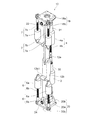
次に、図2及び図3を用いて、本実施形態の脚式ロボット10の脚部12の構造を詳細に説明する。図2は伸長させた脚部の斜視図を示し、図3(a)は伸長させた脚部の正面図を示し、図3(b)は伸長させた脚部の側面図を示す。
Next, the structure of the
図2に示すように、脚部12は、股関節本体18、大腿部12a、膝関節本体19、下腿部12b、足首関節本体20を有する。股関節本体18には、股関節ジョイント22を介して大腿部12aがロール軸及びピッチ軸の回りを回転可能に連結される。大腿部12aには、膝関節本体19がピッチ軸の回りを回転可能に連結される。膝関節本体19には、下腿部12bが結合される。下腿部12bには、足首関節ジョイント24を介して足首関節本体20がロール軸及びピッチ軸の回りを回転可能に連結される。大腿部12aの後方には、大腿部補助リンク31が設けられる。下腿部12bの後方には、下腿部補助リンク32が設けられる。アクチュエータは、大腿部12aの前方に設けられる二つの股関節アクチュエータ7、大腿部12aの後方に設けられる一つの膝関節アクチュエータ4、下腿部12bの前方に設けられる二つの足首関節アクチュエータ6、下腿部12bの後方に設けられる一つの足首関節アクチュエータ3を備える。
As shown in FIG. 2, the
股関節本体18は、プレートを折り曲げて形成され、胴部11に結合される四角形の結合部18aと、結合部18aの対向する一対の辺から折り曲げられた一対のジョイント連結部18bと、を備える。
The
股関節本体18には、受動的な股関節ジョイント22を介して大腿部12aがロール軸及びピッチ軸の回りを回転可能に連結される。図3(b)に示すように、股関節ジョイント22は、互いに直交するロール軸22a1及びピッチ軸22a2を構成する十文字状の本体部22aを有する。本体部22aのロール軸22a1は、股関節本体18の一対のジョイント連結部18bに軸受を介して回転可能に連結される。本体部22aのピッチ軸22a2は、大腿部12aに軸受を介して回転可能に連結される。
A
股関節ジョイント22の本体部22aには、アーム22bが結合される。アーム22bには、大腿部補助リンク31の上端部がピッチ軸の回りを回転可能に連結される。大腿部補助リンク31の下端部は下腿部12bのブラケット12b1にピッチ軸の回りを回転可能に連結される。
An
大腿部補助リンク31には、大腿部補助リンク31の上端部と下端部との間の長さを伸縮させる膝関節アクチュエータ4が設けられる。膝関節アクチュエータ4は、筒状の本体部4aと、本体部4aに対して軸線方向に直線運動する軸部4bと、を備える。軸部4bの外周面には螺旋状のねじ溝が形成される。本体部4aには、軸部4bのねじ溝に螺合するボールねじナット(図示せず)と、ボールねじナットを回転駆動させるモータ(図示せず)が収納される。モータがボールねじナットを回転駆動させると、軸部4bが軸線方向に直線運動して、大腿部補助リンク31を伸縮させる。
The thigh
大腿部12aと股関節本体18との間には、左右一対の股関節アクチュエータ7が架け渡される。股関節アクチュエータ7は大腿部12aの前方に配置されており、大腿部12aを跨ぐように股関節アクチュエータ7及び膝関節アクチュエータ4が配置される。股関節アクチュエータ7は、筒状の本体部7aと、本体部7aに対して軸線方向に直線運動する軸部7bと、を備える。軸部7bの外周面には螺旋状のねじ溝が形成される。本体部7aには、軸部7bのねじ溝に螺合するボールねじナット(図示せず)と、ボールねじナットを回転駆動させるモータ(図示せず)が収納される。モータがボールねじナットを回転駆動させると、軸部7bが軸線方向に直線運動する。
A pair of left and right hip
股関節アクチュエータ7の軸部7bは股関節本体18に球面軸受を介して回転可能に連結される。股関節アクチュエータ7の本体部7aは大腿部12aに球面軸受を介して回転可能に連結される。二つの股関節アクチュエータ7を同時に伸ばしたり、縮めたりすると、大腿部12aが股関節本体18に対してピッチ軸22a2の回りを回転するようになる。一方、二つの股関節アクチュエータ7の一方を伸ばし、他方を縮めると、大腿部12aが股関節本体18に対してロール軸22a1の回りを回転するようになる。二つの股関節アクチュエータ7の回転角度を制御することで、大腿部12aを股関節本体18に対してピッチ軸22a2及びロール軸22a1の回りを回転させることが可能になる。
The
本実施形態のように、股関節本体18と大腿部12aとの間に2自由度の受動的な股関節ジョイント22を介在し、股関節本体18と大腿部12aとの間に二つの股関節アクチュエータ7を架け渡すことで、股関節本体18のピッチ軸及びロール軸に能動的なジョイントとして機能する二つのモータを設けた場合に比べて、数倍の力を発生することができる。必要な力を得るための股関節アクチュエータ7を小型化することができるので、脚部12の小型化が図れる。
As in the present embodiment, a two-degree-of-freedom passive hip joint 22 is interposed between the hip
また、脚式ロボットを二足歩行させるとき、股関節本体18に対して脚部12をロール軸の回りに回転させるのにはトルクが必要になり、股関節本体18に対して脚部12をピッチ軸の回りに回転させるのには速度が必要になる。股関節本体18と大腿部12aとの間に二つの股関節アクチュエータ7を架け渡すことで、ロール軸回りのトルク、及びピッチ軸回りの速度の二つの要求に対応するのが容易になる。
Further, when the legged robot is walked on two legs, torque is required to rotate the
大腿部12aの下端部には、膝関節本体19がピッチ軸19aの回りを回転可能に取り付けられる。この実施形態では、膝関節本体19には下腿部12bが結合される。
A knee
下腿部12bには、足首関節ジョイント24を介して足首関節本体20がロール軸及びピッチ軸の回りを回転可能に連結される。足首関節本体20は、プレートを折り曲げて形成され、足平部21(図1(a)参照)に結合される四角形の結合部20a(図2参照)と、結合部20aの対向する一対の辺から折り曲げられた一対のジョイント連結部20bと、を備える。
An ankle
足首関節ジョイント24は、互いに直交するロール軸24a1及びピッチ軸24a2を構成する十文字状の本体部24aを有する。本体部24aのロール軸24a1が足首関節本体20の一対のジョイント連結部20bに軸受を介して回転可能に連結される。本体部24aのピッチ軸24a2が下腿部12bに軸受を介して回転可能に連結される。
The ankle joint joint 24 includes a cross-shaped
足首関節ジョイント24の本体部24aにはアーム24bが結合される。アーム24bには、下腿部補助リンク32の下端部がピッチ軸の回りを回転可能に連結される。下腿部補助リンク32の上端部は下腿部12bのブラケット12b1にピッチ軸の回りを回転可能に連結される。
An
下腿部補助リンク32には、下腿部補助リンク32の上端部と下端部との間の長さを伸縮させる足首関節アクチュエータ3が設けられる。足首関節アクチュエータ3は、筒状の本体部3aと、本体部3aに対して軸線方向に直線運動する軸部3bと、を備える。軸部3bの外周面には螺旋状のねじ溝が形成される。本体部3aには、軸部3bのねじ溝に螺合するボールねじナット(図示せず)と、ボールねじナットを回転駆動させるモータ(図示せず)が収納される。モータがボールねじナットを回転駆動させると、軸部3bが軸線方向に直線運動する。足首関節アクチュエータ3を伸縮させると、足首関節本体20がピッチ軸の回りに回転する。
The crus
下腿部12bと足首関節本体20との間には、左右一対の足首関節アクチュエータ6が架け渡される。足首関節アクチュエータ6は下腿部12bの前方に配置されており、下腿部12bを跨ぐように足首関節アクチュエータ6及び足首関節アクチュエータ3が配置される。足首関節アクチュエータ6は、筒状の本体部6aと、本体部6aに対して軸線方向に直線運動する軸部6bと、を備える。軸部6bの外周面には螺旋状のねじ溝が形成される。本体部には、軸部6bのねじ溝に螺合するボールねじナット(図示せず)と、ボールねじナットを回転駆動させるモータ(図示せず)が収納される。モータがボールねじナットを回転駆動させると、軸部6bが軸線方向に直線運動する。
A pair of left and right ankle
足首関節アクチュエータ6の軸部6bは足首関節本体20に球面軸受を介して回転可能に連結される。足首関節アクチュエータ6の本体部6aは下腿部12bに球面軸受を介して回転可能に連結される。二つの足首関節アクチュエータ6を同時に伸ばしたり、縮めたりすると、足首関節本体20が下腿部12bに対してピッチ軸24a2の回りを回転するようになる。一方、二つの足首関節アクチュエータ6の一方を伸ばし、他方を縮めると、足首関節本体20が下腿部12bに対してロール軸24a1の回りを回転するようになる。二つの足首関節アクチュエータ6の回転角度を制御することで、足首関節本体20を下腿部12bに対してロール軸24a1及びピッチ軸24a2の回りを回転させることが可能になる。
The
股関節アクチュエータ7、膝関節アクチュエータ4、足首関節アクチュエータ3,6のモータはドライバによって制御される。ドライバは、モータに電力を供給するPWM(pulse width modulation)インバータ等の電力変換器、モータの出力軸の速度及び位置を検出するセンサ、操作マニピュレータからの指令及びセンサからの情報によって電力変換器を制御する制御器を備える。ドライバは相互に通信し合い、別に制御ボックスが無くても同期した動きが可能となっている。
The motors of the hip
次に、大腿部12aに組み込まれる平行リンク41、平行リンク41を構成する大腿部補助リンク31の伸縮動作を説明する。図3(b)に示すように、平行リンク41は平行四辺形を形成する4つのリンクa1,b1,c1,d1から構成される。対向するリンクの長さは等しく、a1=c1,b1=d1の関係がある。リンクa1は股関節ジョイント22のアーム22b、リンクc1は膝関節本体19(膝関節本体19及び下腿部12b)、リンクb1は大腿部12a、リンクd1は大腿部補助リンク31によって構成される。
Next, the expansion and contraction operation of the thigh
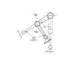
図4(a)は、股関節アクチュエータ7によって大腿部12aをピッチ軸22a2の回りに回転させて、大腿部12aを前方に差し出した状態を示す。大腿部12aをピッチ軸の回りに回転させるとき、平行リンク41の作用により、股関節本体18に対する膝関節本体19(膝関節本体19及び下腿部12b)の姿勢が一定に保たれる。すなわち、図4(a)に示すように大腿部12aを回転させても、膝関節本体19(膝関節本体19及び下腿部12b)の姿勢は図3(b)と同様に鉛直方向を向いている。そして、図4(b)に示すように、膝関節アクチュエータ4が大腿部補助リンク31を縮めることで、膝関節が屈曲するように、鉛直方向を向く膝関節本体19(膝関節本体19及び下腿部12b)の姿勢を変化させることができる。人間の大腿部にも後方に大腿部補助リンク31に相当する筋肉があり、筋肉を収縮させることで膝関節本体の姿勢を変化させることができるようになっている。大腿部12aの後方に大腿部補助リンク31を設け、大腿部補助リンク31を伸縮させることで、人間と同様に少ないエネルギで膝関節本体19の姿勢を変化させることができる。
FIG. 4A shows a state where the
図5は、大腿部補助リンク31を伸縮させることによって、膝関節アクチュエータ4のエネルギを低減できる理由を説明する図である。まず、比較例として、股関節及び膝関節にアクチュエータを設けた場合について説明する。比較例において、脚部全体が直立した状態から大腿部12aを角度θ1だけ揺動させ、同時に下腿部12bを大腿部12aの軸線に対してθ2だけ曲げることを想定する。ただし、本実施形態との比較を容易にするために、θ2=2θ1とし、大腿部12aをθ1揺動させるためのエネルギをE1とし、下腿部をθ2(=2θ1)曲げるに要するエネルギをE2とし、さらにθ2=2θ1の関係があることからE2=2E1と仮定する。このように仮定すると、脚部を直立した状態から図5に示す屈曲状態(図4(b)と同一の屈曲状態)に至らしめるための総エネルギはE1+E2=3E1となる。
FIG. 5 is a diagram for explaining the reason why the energy of the knee
これに対して、本実施形態においても同様な動作をさせると、脚部の長さや質量が比較例と同じであれば、股関節アクチュエータ7により大腿部12aをθ1遊動させるに要するエネルギはE1である。この大腿部12aの揺動時、平行リンクの作用により、図4(a)に示すように、下腿部が角度θ1だけ大腿部12aの軸線に対して曲がる。平行リンクの作用により下腿部12bが角度θ1曲がっているので、図4(b)に示すように、さらに下腿部12bを大腿部12aの軸線に対して2θ1とするために、膝関節アクチュエータ4により下腿部12bを曲げる角度はθ1となり、それに要するエネルギはE1で済む。すなわち、脚部の屈曲完了までに要する総エネルギは2E1で済む。つまり、比較例における膝関節に設けられているアクチュエータが2E1の出力を要するが故に大形であるのに対し、本実施形態ではE1の出力に止まる膝関節アクチュエータ4を設ければよいので、下肢構造の小型化が達成され、消費エネルギも少なくなる。
On the other hand, if the same operation is performed in the present embodiment, if the leg length and mass are the same as those in the comparative example, the energy required to move the
また、図4に示すように、下腿部12bの後方に下腿部補助リンク32を配置し、下腿部補助リンク32を足首関節アクチュエータ3によって伸縮させることで、下腿部12bに対する足首関節本体20の姿勢を変化させることができる。人間の下腿部の後方にも下腿部補助リンク32に相当する筋肉があり、筋肉を収縮させることで足首関節本体20の姿勢を変化させることができるようになっている。下腿部12bの後方に下腿部補助リンク32を配置し、下腿部補助リンク32を伸縮させることで、人間と同様に少ないエネルギで足首関節本体20の姿勢を変化させることができる。
Further, as shown in FIG. 4, an ankle joint with respect to the
なお、本発明は上記実施形態に限られることはなく、本発明の要旨を変更しない範囲で様々な実施形態に変更可能である。 In addition, this invention is not limited to the said embodiment, It can change into various embodiment in the range which does not change the summary of this invention.
上記実施形態では、股関節本体と大腿部とをロール軸及びピッチ軸の回りに回転可能に連結しているが、股関節本体と大腿部とをピッチ軸の回りにのみ回転可能に連結することもできる。この場合、平行リンクを構成する大腿部補助リンクは、一端部が股関節本体にピッチ軸の回りを回転可能に連結され、他端部が膝関節本体にピッチ軸の回りを回転可能に連結される。 In the above embodiment, the hip joint body and the thigh are connected to be rotatable about the roll axis and the pitch axis, but the hip joint body and the thigh are connected to be rotatable only about the pitch axis. You can also. In this case, one end of the thigh auxiliary link constituting the parallel link is connected to the hip joint body so as to be rotatable around the pitch axis, and the other end is connected to the knee joint body so as to be rotatable around the pitch axis. The
上記実施形態では、股関節本体と大腿部との間に架け渡されるアクチュエータとして、直動型のアクチュエータモータを使用しているが、回転型のアクチュエータを使用することもできる。この場合、回転型のアクチュエータは、大腿部に結合されるモータ、モータの出力に結合されるサーボホーン、一端部がサーボホーンに球面軸受を介して回転可能に連結され、他端部が股関節本体に球面軸受を介して回転可能に連結されるリンクとから構成することができる。 In the above-described embodiment, a direct acting actuator motor is used as an actuator spanned between the hip joint body and the thigh, but a rotary actuator can also be used. In this case, the rotary actuator includes a motor coupled to the thigh, a servo horn coupled to the motor output, one end rotatably connected to the servo horn via a spherical bearing, and the other end hip joint It can be comprised from the link connected with a main body through a spherical bearing so that rotation is possible.
上記実施形態では、膝関節本体と下腿部とを結合しているが、膝関節本体と下腿部とをピッチ軸の回りに回転可能に連結することもできる。 In the above embodiment, the knee joint body and the crus are connected, but the knee joint body and the crus may be connected to be rotatable about the pitch axis.
上記実施形態では、股関節本体を胴部に結合しているが、股関節本体と胴部とを一体のフレームから構成することもできる。上記実施形態では、足首関節本体を足平部に結合しているが、足首関節本体と足平部とを一体のフレームから構成することもできる。 In the embodiment described above, the hip joint body is coupled to the trunk, but the hip joint body and the trunk can also be configured from an integral frame. In the above-described embodiment, the ankle joint main body is coupled to the foot portion, but the ankle joint main body and the foot portion can also be configured from an integral frame.
上記実施形態では、脚部を揺動させる駆動源としてモータを使用しているが、駆動源としてはこの他に、空圧又は油圧シリンダー、リニアモータ、人工筋アクチュエータ等種々のものを利用することができる。 In the above embodiment, a motor is used as a drive source for swinging the leg portion, but various other devices such as a pneumatic or hydraulic cylinder, a linear motor, and an artificial muscle actuator can be used as the drive source. Can do.
3…足首関節アクチュエータ,4…膝関節アクチュエータ,7…股関節アクチュエータ,10…脚式ロボット,12…脚部,12a…大腿部,12b…下腿部,18…股関節本体,19…膝関節本体,20…足首関節本体,22…股関節ジョイント,24…足首関節ジョイント,31…大腿部補助リンク,32…下腿部補助リンク,41…平行リンク
DESCRIPTION OF
Claims (4)
大腿部と、
前記股関節本体に対して前記大腿部を少なくともピッチ軸の回りに回転可能に連結する股関節ジョイントと、
前記大腿部にピッチ軸の回りを回転可能に連結される膝関節本体と、
一端部が前記股関節本体又は前記股関節ジョイントにピッチ軸の回りを回転可能に連結されると共に、他端部が前記膝関節本体にピッチ軸の回りを回転可能に連結される大腿部補助リンクと、
前記大腿部補助リンクの前記一端部から前記他端部までの長さを伸縮させる膝関節アクチュエータと、を備え、
前記股関節本体又は前記股関節ジョイント、前記大腿部、前記膝関節本体、及び前記大腿部補助リンクは、平行四辺形を形成する平行リンクを構成し、
前記大腿部がピッチ軸の回りを回転するとき、前記平行リンクの作用により、前記股関節本体に対する前記膝関節本体の姿勢が一定に保たれ、
そして、前記膝関節アクチュエータによって前記大腿部補助リンクを伸縮させることで、前記股関節本体に対して前記膝関節本体の姿勢を変化させる脚式ロボットの下肢構造。 The hip body,
The thigh,
A hip joint that connects the thigh to the hip joint body so as to be rotatable at least about a pitch axis;
A knee joint body coupled to the thigh for rotation about a pitch axis;
A thigh auxiliary link having one end connected to the hip joint body or the hip joint joint so as to be rotatable about the pitch axis, and the other end connected to the knee joint body so as to be rotatable about the pitch axis; ,
A knee joint actuator that expands and contracts the length from the one end to the other end of the thigh auxiliary link ,
The hip joint body or the hip joint joint, the thigh, the knee joint body, and the thigh auxiliary link constitute a parallel link forming a parallelogram,
When the thigh rotates about the pitch axis, the action of the parallel link keeps the posture of the knee joint body relative to the hip joint body,
And the leg structure of a legged robot that changes the posture of the knee joint body with respect to the hip joint body by expanding and contracting the thigh auxiliary link by the knee joint actuator .
前記大腿部と前記股関節本体との間には、前記股関節本体に対して前記大腿部を前記ピッチ軸及び前記ロール軸の回りに回転駆動させる股関節アクチュエータが架け渡されることを特徴とする請求項1に記載の脚式ロボットの下肢構造。 The hip joint is connected to the hip joint body so that the thigh can rotate about the pitch axis and the roll axis,
Between the hip joint body and the thigh, and characterized in that the hip joint actuator for rotationally driving the thigh around the pitch Jiku及beauty before Symbol roll axis relative to the hip joint body is bridged The leg structure of the legged robot according to claim 1.
前記膝関節本体に結合される下腿部と、
足首関節本体と、
前記下腿部に前記足首関節本体を少なくともピッチ軸の回りに回転可能に連結する足首関節ジョイントと、
一端部が前記下腿部にピッチ軸の回りを回転可能に連結されると共に、他端部が前記足首関節ジョイントにピッチ軸の回りを回転可能に連結される下腿部補助リンクと、
前記下腿部補助リンクの前記一端部から前記他端部までの長さを伸縮させる足首関節アクチュエータと、を備えることを特徴とする請求項1又は2に記載の脚式ロボットの下肢構造。 The legged robot further includes:
A lower leg coupled to the knee joint body;
An ankle joint body,
An ankle joint joint for connecting the ankle joint body to the crus so as to be rotatable at least about a pitch axis;
A crus auxiliary link, one end of which is connected to the crus for rotation about the pitch axis, and the other end is connected to the ankle joint joint for rotation about the pitch axis;
The leg structure of the legged robot according to claim 1 , further comprising: an ankle joint actuator that expands and contracts a length from the one end to the other end of the crus auxiliary link.
Priority Applications (6)
| Application Number | Priority Date | Filing Date | Title |
|---|---|---|---|
| JP2012124511A JP5976401B2 (en) | 2012-05-31 | 2012-05-31 | Lower leg structure of legged robot and legged robot |
| US14/401,892 US9446514B2 (en) | 2012-05-31 | 2013-04-11 | Lower limb structure for legged robot, and legged robot |
| PCT/JP2013/060940 WO2013179782A1 (en) | 2012-05-31 | 2013-04-11 | Lower limb structure for legged robot, and legged robot |
| DE112013002741.0T DE112013002741T5 (en) | 2012-05-31 | 2013-04-11 | Lower limb structure for walking robots and walking robots |
| KR1020147036367A KR101979480B1 (en) | 2012-05-31 | 2013-04-11 | Lower limb structure for legged robot, and legged robot |
| CN201380028692.4A CN104349871B (en) | 2012-05-31 | 2013-04-11 | The lower limb structure and legged mobile robot of legged mobile robot |
Applications Claiming Priority (1)
| Application Number | Priority Date | Filing Date | Title |
|---|---|---|---|
| JP2012124511A JP5976401B2 (en) | 2012-05-31 | 2012-05-31 | Lower leg structure of legged robot and legged robot |
Publications (3)
| Publication Number | Publication Date |
|---|---|
| JP2013248699A JP2013248699A (en) | 2013-12-12 |
| JP2013248699A5 JP2013248699A5 (en) | 2015-07-09 |
| JP5976401B2 true JP5976401B2 (en) | 2016-08-23 |
Family
ID=49672990
Family Applications (1)
| Application Number | Title | Priority Date | Filing Date |
|---|---|---|---|
| JP2012124511A Active JP5976401B2 (en) | 2012-05-31 | 2012-05-31 | Lower leg structure of legged robot and legged robot |
Country Status (6)
| Country | Link |
|---|---|
| US (1) | US9446514B2 (en) |
| JP (1) | JP5976401B2 (en) |
| KR (1) | KR101979480B1 (en) |
| CN (1) | CN104349871B (en) |
| DE (1) | DE112013002741T5 (en) |
| WO (1) | WO2013179782A1 (en) |
Families Citing this family (74)
| Publication number | Priority date | Publication date | Assignee | Title |
|---|---|---|---|---|
| US9789603B2 (en) | 2011-04-29 | 2017-10-17 | Sarcos Lc | Teleoperated robotic system |
| US9764464B2 (en) * | 2011-08-03 | 2017-09-19 | The Boeing Company | Robot including telescopic assemblies for positioning an end effector |
| US9616580B2 (en) | 2012-05-14 | 2017-04-11 | Sarcos Lc | End effector for a robotic arm |
| JP6359824B2 (en) * | 2013-03-25 | 2018-07-18 | 太陽インキ製造株式会社 | Photosensitive resin composition, cured film thereof and printed wiring board |
| US10766133B2 (en) * | 2014-05-06 | 2020-09-08 | Sarcos Lc | Legged robotic device utilizing modifiable linkage mechanism |
| US10406676B2 (en) | 2014-05-06 | 2019-09-10 | Sarcos Lc | Energy recovering legged robotic device |
| US10512583B2 (en) | 2014-05-06 | 2019-12-24 | Sarcos Lc | Forward or rearward oriented exoskeleton |
| US10533542B2 (en) | 2014-05-06 | 2020-01-14 | Sarcos Lc | Rapidly modulated hydraulic supply for a robotic device |
| KR101627138B1 (en) * | 2014-09-04 | 2016-06-07 | 한국생산기술연구원 | Walking robot leg structure |
| JP6228097B2 (en) * | 2014-10-06 | 2017-11-08 | 本田技研工業株式会社 | Mobile robot |
| CN104401419B (en) * | 2014-11-25 | 2017-03-01 | 北京工业大学 | A kind of new biped humanoid robot system based on Pneumatic artificial muscle |
| JP6677970B2 (en) * | 2015-02-20 | 2020-04-08 | 川崎重工業株式会社 | Industrial robot |
| CN106143665A (en) * | 2015-04-21 | 2016-11-23 | 电子科技大学 | Trunk mechanism of a kind of flexible robot |
| GB2538714A (en) | 2015-05-25 | 2016-11-30 | Robotical Ltd | Robot Leg |
| US10189519B2 (en) * | 2015-05-29 | 2019-01-29 | Oregon State University | Leg configuration for spring-mass legged locomotion |
| US9878751B1 (en) | 2015-10-08 | 2018-01-30 | Boston Dynamics, Inc. | Three-piston ankle mechanism of a legged robot and associated control system |
| CN106741277B (en) * | 2015-11-20 | 2020-10-30 | 沈阳新松机器人自动化股份有限公司 | Hybrid mechanical leg mechanism |
| CN105480322B (en) * | 2015-12-17 | 2018-01-30 | 哈尔滨龙海特机器人科技有限公司 | One kind is used for legged type robot parallel leg structure of running at a high speed |
| WO2017214259A1 (en) * | 2016-06-07 | 2017-12-14 | Worcester Polytechnic Institute | Biologically-inspired joints and systems and methods of use thereof |
| CN106314588A (en) * | 2016-09-19 | 2017-01-11 | 南宁邃丛赋语科技开发有限责任公司 | Automatically controlled robot walking on two feet |
| KR20180035626A (en) * | 2016-09-29 | 2018-04-06 | 최호림 | Walking Robot device |
| CN106493738A (en) * | 2016-10-26 | 2017-03-15 | 河南工业大学 | A kind of assiatant child with both legs walk apery educational robot |
| US10821614B2 (en) | 2016-11-11 | 2020-11-03 | Sarcos Corp. | Clutched joint modules having a quasi-passive elastic actuator for a robotic assembly |
| US10828767B2 (en) | 2016-11-11 | 2020-11-10 | Sarcos Corp. | Tunable actuator joint modules having energy recovering quasi-passive elastic actuators with internal valve arrangements |
| US10765537B2 (en) | 2016-11-11 | 2020-09-08 | Sarcos Corp. | Tunable actuator joint modules having energy recovering quasi-passive elastic actuators for use within a robotic system |
| US10919161B2 (en) | 2016-11-11 | 2021-02-16 | Sarcos Corp. | Clutched joint modules for a robotic system |
| KR101876252B1 (en) * | 2016-11-22 | 2018-07-10 | 한국과학기술연구원 | Lower body of robot comprising parallel link structure and moving robot apparatus comprising the same |
| US11511446B2 (en) * | 2016-11-24 | 2022-11-29 | Kawasaki Jukogyo Kabushiki Kaisha | Joint structure for robot |
| US10253855B2 (en) | 2016-12-15 | 2019-04-09 | Boston Dynamics, Inc. | Screw actuator for a legged robot |
| US10337561B2 (en) * | 2016-12-15 | 2019-07-02 | Boston Dynamics, Inc. | Transmission with integrated overload protection for a legged robot |
| CN106672105B (en) * | 2017-03-01 | 2023-03-21 | 吉林大学 | Bionic four-legged robot hind limb with integral tensioning structure |
| CN106726362B (en) * | 2017-03-03 | 2023-04-07 | 中国科学院合肥物质科学研究院 | Hip and knee integrated joint device for exoskeleton robot and exoskeleton robot |
| CN106726363B (en) * | 2017-03-13 | 2023-11-17 | 东北大学 | Wearable bionic hydraulic lower limb rehabilitation walking-assisting mechanical device |
| WO2018170638A1 (en) * | 2017-03-18 | 2018-09-27 | 深圳市方鹏科技有限公司 | Lower limb walking mechanism system for robot |
| US10843330B2 (en) | 2017-12-07 | 2020-11-24 | Sarcos Corp. | Resistance-based joint constraint for a master robotic system |
| US11331809B2 (en) | 2017-12-18 | 2022-05-17 | Sarcos Corp. | Dynamically controlled robotic stiffening element |
| CN108082325A (en) * | 2017-12-21 | 2018-05-29 | 江苏集萃智能制造技术研究所有限公司 | A kind of double-foot robot lower limb mechanism of hydraulic-driven |
| CN109969284A (en) * | 2017-12-28 | 2019-07-05 | 沈阳新松机器人自动化股份有限公司 | Hybrid mechanical leg organization and biped robot |
| CN107985439B (en) * | 2017-12-29 | 2023-12-05 | 北京钢铁侠科技有限公司 | Leg mechanism of humanoid robot |
| CN108095983A (en) * | 2018-02-05 | 2018-06-01 | 河北工程大学 | A kind of two sufficient walking mechanisms for high amputation patient |
| US10719085B2 (en) * | 2018-02-22 | 2020-07-21 | Boston Dynamics, Inc. | Mobile robot sitting and standing |
| KR102586197B1 (en) | 2018-12-10 | 2023-10-11 | 삼성전자주식회사 | Motion assist apparatus |
| WO2020123833A1 (en) * | 2018-12-14 | 2020-06-18 | Moog Inc. | Humanoid lower body robot electro hydrostatic actuating ankle |
| JP7150589B2 (en) * | 2018-12-25 | 2022-10-11 | 株式会社神戸製鋼所 | Actuator device, movement mechanism using the same, equipment |
| US10906191B2 (en) | 2018-12-31 | 2021-02-02 | Sarcos Corp. | Hybrid robotic end effector |
| US11241801B2 (en) | 2018-12-31 | 2022-02-08 | Sarcos Corp. | Robotic end effector with dorsally supported actuation mechanism |
| US11351675B2 (en) | 2018-12-31 | 2022-06-07 | Sarcos Corp. | Robotic end-effector having dynamic stiffening elements for conforming object interaction |
| CN110236884A (en) * | 2019-07-04 | 2019-09-17 | 青岛市中心医院 | A kind of all-around intelligent hip knee ankle-joint passive rehabilitation training device |
| CN110696941B (en) * | 2019-09-19 | 2024-04-09 | 浙江工业大学 | Redundant hybrid electrohydraulic hybrid driving anthropomorphic mechanical leg |
| CN110696944A (en) * | 2019-11-11 | 2020-01-17 | 路邦科技授权有限公司 | Leg remote control system of bionic robot and control method thereof |
| KR102256225B1 (en) * | 2019-11-20 | 2021-05-26 | 주식회사 엔젤로보틱스 | Lower-Body Assistance Robot |
| KR20210065644A (en) | 2019-11-27 | 2021-06-04 | 주식회사 에프알티 | Wearable exoskeleton robot equipped with pneumatic module for leg |
| CN111017063B (en) * | 2019-12-17 | 2022-03-22 | 上海哲谦应用科技有限公司 | Direct-drive type humanoid biped robot |
| CN110962959B (en) * | 2019-12-24 | 2022-03-08 | 深圳市行者机器人技术有限公司 | Robot and mechanical leg thereof |
| CN111098951A (en) * | 2019-12-30 | 2020-05-05 | 深圳市优必选科技股份有限公司 | Humanoid robot and leg structure thereof |
| CN112319209A (en) * | 2020-11-18 | 2021-02-05 | 内蒙古第一机械集团股份有限公司 | Driving device suitable for leg joint movement of robot |
| US11833676B2 (en) | 2020-12-07 | 2023-12-05 | Sarcos Corp. | Combining sensor output data to prevent unsafe operation of an exoskeleton |
| US11794345B2 (en) | 2020-12-31 | 2023-10-24 | Sarcos Corp. | Unified robotic vehicle systems and methods of control |
| CN112937717B (en) * | 2021-02-03 | 2023-06-13 | 南方科技大学 | Bionic mechanical leg and bionic robot |
| CN112937720B (en) * | 2021-02-05 | 2021-09-28 | 重庆工程职业技术学院 | Walking robot |
| CN112874656B (en) * | 2021-03-23 | 2023-03-31 | 上海智能制造功能平台有限公司 | Leg mechanism of robot and robot |
| CN115195899B (en) * | 2021-04-09 | 2023-06-30 | 暗物智能科技(广州)有限公司 | Wheel foot switching type robot |
| CN113635992B (en) * | 2021-06-15 | 2023-02-10 | 上海大学 | Bionic jumping leg driven by double-joint pneumatic artificial muscle |
| CN113401246B (en) * | 2021-07-21 | 2022-08-12 | 北京理工大学 | Leg and foot mechanism of bionic robot |
| CN114161472B (en) * | 2021-11-17 | 2024-02-13 | 深圳市优必选科技股份有限公司 | Hip waist joint structure and humanoid robot |
| CN114056450B (en) * | 2021-11-26 | 2022-11-29 | 合肥工业大学 | Wheel-foot type folding leg for unmanned metamorphic vehicle |
| CN113998028A (en) * | 2021-12-22 | 2022-02-01 | 成都理工大学 | Two-degree-of-freedom base joint structure of foot type robot |
| CN115056883A (en) * | 2022-05-06 | 2022-09-16 | 纯米科技(上海)股份有限公司 | Leg structure and quadruped robot |
| CN115056884B (en) * | 2022-06-27 | 2023-10-17 | 北京工业大学 | Humanoid robot leg structure with differential joint decoupling and inertia upward movement characteristics |
| US11826907B1 (en) | 2022-08-17 | 2023-11-28 | Sarcos Corp. | Robotic joint system with length adapter |
| US11717956B1 (en) | 2022-08-29 | 2023-08-08 | Sarcos Corp. | Robotic joint system with integrated safety |
| US11897132B1 (en) | 2022-11-17 | 2024-02-13 | Sarcos Corp. | Systems and methods for redundant network communication in a robot |
| US11924023B1 (en) | 2022-11-17 | 2024-03-05 | Sarcos Corp. | Systems and methods for redundant network communication in a robot |
| CN116729520B (en) * | 2023-08-11 | 2023-10-20 | 太原理工大学 | Bionic four-foot robot based on double-layer corrugated pipe pneumatic soft driver |
Family Cites Families (15)
| Publication number | Priority date | Publication date | Assignee | Title |
|---|---|---|---|---|
| FI100098B (en) * | 1995-11-06 | 1997-09-30 | Plustech Oy | foot mechanism |
| US6109378A (en) | 1995-11-06 | 2000-08-29 | Plustech Oy | Leg mechanism |
| CN1293607A (en) * | 1999-01-28 | 2001-05-02 | 索尼公司 | Joint device for robot device and leg-walking robot device |
| CN1081515C (en) * | 1999-04-05 | 2002-03-27 | 张平顺 | Two-leg walking machine |
| US6898485B2 (en) * | 2000-11-20 | 2005-05-24 | Sony Corporation | Device and method for controlling operation of legged robot, and robot device |
| JP2002264046A (en) | 2001-03-12 | 2002-09-18 | Rikogaku Shinkokai | Master-slave type remote-operated biped walking robot |
| KR100541433B1 (en) * | 2002-12-23 | 2006-01-11 | 삼성전자주식회사 | Walking Robot with Two Legs |
| KR20040068438A (en) * | 2003-01-25 | 2004-07-31 | 삼성전자주식회사 | Walking type robot and a moving method thereof |
| JP4635135B2 (en) * | 2004-06-28 | 2011-02-16 | 学校法人 芝浦工業大学 | Walking device |
| JP4526332B2 (en) * | 2004-09-06 | 2010-08-18 | 本田技研工業株式会社 | Leg joint assist device for legged mobile robot |
| JP4911525B2 (en) * | 2007-10-23 | 2012-04-04 | 本田技研工業株式会社 | Biped robot |
| KR101182620B1 (en) * | 2007-10-23 | 2012-09-14 | 혼다 기켄 고교 가부시키가이샤 | Two-legged walking robot |
| KR101484943B1 (en) * | 2008-05-30 | 2015-01-21 | 삼성전자 주식회사 | Walking Robot |
| KR101464125B1 (en) * | 2008-06-05 | 2014-12-04 | 삼성전자주식회사 | Walking Robot |
| JP5539040B2 (en) * | 2010-06-04 | 2014-07-02 | 本田技研工業株式会社 | Legged mobile robot |
-
2012
- 2012-05-31 JP JP2012124511A patent/JP5976401B2/en active Active
-
2013
- 2013-04-11 DE DE112013002741.0T patent/DE112013002741T5/en active Pending
- 2013-04-11 CN CN201380028692.4A patent/CN104349871B/en active Active
- 2013-04-11 WO PCT/JP2013/060940 patent/WO2013179782A1/en active Application Filing
- 2013-04-11 US US14/401,892 patent/US9446514B2/en active Active
- 2013-04-11 KR KR1020147036367A patent/KR101979480B1/en active IP Right Grant
Also Published As
| Publication number | Publication date |
|---|---|
| JP2013248699A (en) | 2013-12-12 |
| US20150122559A1 (en) | 2015-05-07 |
| KR101979480B1 (en) | 2019-08-28 |
| KR20150016362A (en) | 2015-02-11 |
| CN104349871A (en) | 2015-02-11 |
| WO2013179782A1 (en) | 2013-12-05 |
| DE112013002741T5 (en) | 2015-03-19 |
| US9446514B2 (en) | 2016-09-20 |
| CN104349871B (en) | 2017-08-25 |
Similar Documents
| Publication | Publication Date | Title |
|---|---|---|
| JP5976401B2 (en) | Lower leg structure of legged robot and legged robot | |
| JP5872846B2 (en) | Robot joint structure and humanoid robot incorporating this joint structure | |
| TWI522217B (en) | Joint structure of robot and robot having the same incorporated therein | |
| JP6803338B2 (en) | 2 degree of freedom drive mechanism | |
| WO2013179783A1 (en) | Lower limb structure for legged robot, and legged robot | |
| KR101457147B1 (en) | Humanoid robot and shoulder joint assembly thereof | |
| US20090301798A1 (en) | Walking robot | |
| JP5373880B2 (en) | Legged robot | |
| JP2013248699A5 (en) | ||
| JPH03184782A (en) | Joint structure for leg type walking robot | |
| JP5877686B2 (en) | Robot joint structure and humanoid robot incorporating this joint structure | |
| JP5681564B2 (en) | robot | |
| JP4442464B2 (en) | Articulated arm mechanism | |
| JP2001239478A (en) | Leg type mobile robot and movable leg unit connecting structure for leg type mobile robot | |
| JP2008044066A (en) | Legged robot | |
| JP4289447B2 (en) | Robot device and joint axis drive device | |
| JP3375202B2 (en) | Two-joint arm mechanism equipped with two-joint simultaneous drive source and operation control method thereof | |
| JPS61211177A (en) | Articulated leg mechanism having load reduction mechanism | |
| JP7261082B2 (en) | walking robot | |
| JP6705658B2 (en) | Legged mobile robot | |
| WO2019097814A1 (en) | Extending and retracting mechanism | |
| CN220128828U (en) | Robot hip joint assembly and robot | |
| JP5879068B2 (en) | Robot joint actuator and legged mobile robot |
Legal Events
| Date | Code | Title | Description |
|---|---|---|---|
| A521 | Request for written amendment filed |
Free format text: JAPANESE INTERMEDIATE CODE: A523 Effective date: 20150522 |
|
| A621 | Written request for application examination |
Free format text: JAPANESE INTERMEDIATE CODE: A621 Effective date: 20150522 |
|
| A131 | Notification of reasons for refusal |
Free format text: JAPANESE INTERMEDIATE CODE: A131 Effective date: 20160308 |
|
| A521 | Request for written amendment filed |
Free format text: JAPANESE INTERMEDIATE CODE: A523 Effective date: 20160426 |
|
| TRDD | Decision of grant or rejection written | ||
| A01 | Written decision to grant a patent or to grant a registration (utility model) |
Free format text: JAPANESE INTERMEDIATE CODE: A01 Effective date: 20160705 |
|
| A61 | First payment of annual fees (during grant procedure) |
Free format text: JAPANESE INTERMEDIATE CODE: A61 Effective date: 20160720 |
|
| R150 | Certificate of patent or registration of utility model |
Ref document number: 5976401 Country of ref document: JP Free format text: JAPANESE INTERMEDIATE CODE: R150 |
|
| R250 | Receipt of annual fees |
Free format text: JAPANESE INTERMEDIATE CODE: R250 |
|
| R250 | Receipt of annual fees |
Free format text: JAPANESE INTERMEDIATE CODE: R250 |
|
| R250 | Receipt of annual fees |
Free format text: JAPANESE INTERMEDIATE CODE: R250 |
|
| R250 | Receipt of annual fees |
Free format text: JAPANESE INTERMEDIATE CODE: R250 |
|
| R250 | Receipt of annual fees |
Free format text: JAPANESE INTERMEDIATE CODE: R250 |