EP1433656A2 - Einrichtung zum automatischen Schalten von Beleuchtungseinrichtungen bei Fahrzeugen - Google Patents
Einrichtung zum automatischen Schalten von Beleuchtungseinrichtungen bei Fahrzeugen Download PDFInfo
- Publication number
- EP1433656A2 EP1433656A2 EP03013114A EP03013114A EP1433656A2 EP 1433656 A2 EP1433656 A2 EP 1433656A2 EP 03013114 A EP03013114 A EP 03013114A EP 03013114 A EP03013114 A EP 03013114A EP 1433656 A2 EP1433656 A2 EP 1433656A2
- Authority
- EP
- European Patent Office
- Prior art keywords
- sensor
- signal
- conversion characteristic
- conversion
- vehicle
- Prior art date
- Legal status (The legal status is an assumption and is not a legal conclusion. Google has not performed a legal analysis and makes no representation as to the accuracy of the status listed.)
- Granted
Links
Images
Classifications
-
- B—PERFORMING OPERATIONS; TRANSPORTING
- B60—VEHICLES IN GENERAL
- B60Q—ARRANGEMENT OF SIGNALLING OR LIGHTING DEVICES, THE MOUNTING OR SUPPORTING THEREOF OR CIRCUITS THEREFOR, FOR VEHICLES IN GENERAL
- B60Q1/00—Arrangement of optical signalling or lighting devices, the mounting or supporting thereof or circuits therefor
- B60Q1/02—Arrangement of optical signalling or lighting devices, the mounting or supporting thereof or circuits therefor the devices being primarily intended to illuminate the way ahead or to illuminate other areas of way or environments
- B60Q1/04—Arrangement of optical signalling or lighting devices, the mounting or supporting thereof or circuits therefor the devices being primarily intended to illuminate the way ahead or to illuminate other areas of way or environments the devices being headlights
- B60Q1/14—Arrangement of optical signalling or lighting devices, the mounting or supporting thereof or circuits therefor the devices being primarily intended to illuminate the way ahead or to illuminate other areas of way or environments the devices being headlights having dimming means
- B60Q1/1415—Dimming circuits
- B60Q1/1423—Automatic dimming circuits, i.e. switching between high beam and low beam due to change of ambient light or light level in road traffic
-
- B—PERFORMING OPERATIONS; TRANSPORTING
- B60—VEHICLES IN GENERAL
- B60Q—ARRANGEMENT OF SIGNALLING OR LIGHTING DEVICES, THE MOUNTING OR SUPPORTING THEREOF OR CIRCUITS THEREFOR, FOR VEHICLES IN GENERAL
- B60Q2300/00—Indexing codes for automatically adjustable headlamps or automatically dimmable headlamps
- B60Q2300/30—Indexing codes relating to the vehicle environment
- B60Q2300/31—Atmospheric conditions
- B60Q2300/312—Adverse weather
-
- B—PERFORMING OPERATIONS; TRANSPORTING
- B60—VEHICLES IN GENERAL
- B60Q—ARRANGEMENT OF SIGNALLING OR LIGHTING DEVICES, THE MOUNTING OR SUPPORTING THEREOF OR CIRCUITS THEREFOR, FOR VEHICLES IN GENERAL
- B60Q2300/00—Indexing codes for automatically adjustable headlamps or automatically dimmable headlamps
- B60Q2300/30—Indexing codes relating to the vehicle environment
- B60Q2300/31—Atmospheric conditions
- B60Q2300/314—Ambient light
-
- B—PERFORMING OPERATIONS; TRANSPORTING
- B60—VEHICLES IN GENERAL
- B60Q—ARRANGEMENT OF SIGNALLING OR LIGHTING DEVICES, THE MOUNTING OR SUPPORTING THEREOF OR CIRCUITS THEREFOR, FOR VEHICLES IN GENERAL
- B60Q2300/00—Indexing codes for automatically adjustable headlamps or automatically dimmable headlamps
- B60Q2300/30—Indexing codes relating to the vehicle environment
- B60Q2300/33—Driving situation
- B60Q2300/337—Tunnels or bridges
Definitions
- DE 195 23 262 A1 is a generic device for automatic switching of lighting devices known from vehicles. Such facilities are used to drive a motor vehicle from manual adjustment of lighting equipment of his vehicle to the current lighting conditions of the Relieve the vehicle environment. This is not only intended to ensure be that due to weather or time conditional deterioration in lighting conditions, the vehicle headlights are switched on in time, but also that turning on the driving lights guaranteed when entering tunnels, underground garages, etc. is what is often omitted for convenience and then leads to corresponding security deficiencies.
- the Direction sensor when approaching a bridge, the Direction sensor in general bright daylight conditions initially "dark ahead" during the global sensor still reports “bright". The vehicle drives in the shade the bridge, the global sensor reports “dark” during the direction sensor that already has the lighting conditions beyond the bridge, "bright ahead” reports. However, it is not a bridge, but a an elongated tunnel or something similar the entrance both sensors “dark” respectively "dark ahead".
- a suitably designed evaluation device is able to use the different Signal combinations towards the right situation close and the appropriate lighting measures take.
- a disadvantage of the prior art is that the reliable differentiation of different situations very much from the general lighting conditions is dependent. So it is comparatively easy to manage bright, sunny weather, causing excessive shadowing and therefore leads to considerable contrast sharpness. Absence of such Contrasts, for example in cloudy weather or dawn, it can happen that for example, when driving through a bridge, the direction sensor still emits signals that are "dark ahead "are to be interpreted if the global sensor already reports “dark”. In this case it would be superfluous the headlights on and just behind the Bridge when direction and global sensor "bright” again or “bright ahead” report, switch off what to a possibly more irritating to oncoming traffic Flashing effect leads. This can basically be done with the adjustment the evaluation software can be countered that depend different from the global lighting conditions Evaluation programs ready. However, this is programming-related highly complex, since it is the Evaluation programs usually make the implementation more complex Fuzzy logic methods.
- the device according to the invention according to claim 1 builds on the prior art in that in the storage means at least one second A / D conversion characteristic for the directional sensor is stored and digitization of the direction sensor signal depending on one that represents the general lighting conditions Signal according to the first or the second A / D conversion characteristic he follows.
- the adaptation to the lighting conditions takes place rather in the comparatively simple digitization step by applying one to the current one A / D conversion characteristic curve adapted to the lighting conditions.
- Such characteristics are, for example, as little memory-intensive, Configurable conversion tables storable.
- the design of the tables can be due to current calculations or from empirical values.
- it is also possible to change the characteristic curves save as math functions, which increases the current calculation effort, however, the memory requirement is further reduced.
- the invention according to claim 2 is particularly advantageous designed because there is a flatter slope of the A / D conversion characteristics as compression of the temporal direction sensor signal for example when passing through a Bridge or underpass. This is the through twilight-related, undesirable spreading of the same Signal counteracted, so that the shape of the Digitized twilight according to the second A / D conversion characteristic temporal sensor signal that in bright daylight digitized according to the first A / D conversion characteristic is approximated.
- the evaluation software can therefore process approximately the same signal in both cases and get the same correct results without a special program adjustment according to the current one To have to perform lighting conditions.
- the measure according to claim 4 leads to a loss of resolution when recording the lighting conditions through the sensor, but leads to the desired change in shape the temporal sensor signal.
- the advantages of the further development of the invention Device according to claim 5 are that the A / D conversion characteristics get a particularly simple shape, which is particularly good for storing in shape a mathematical function because the conversion can be done quickly and easily.
- the invention is advantageous in this way trained that to capture general lighting conditions no separate sensor is required at the same time, this is the switchover between the characteristic curves initiating signal is sufficiently stable in time and not with the short-term, current shadowing of the Vehicle varies.
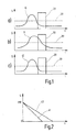
- Figure 1a shows schematically an exemplary, temporal Course of the signal 10 S (t) of a direction sensor in the direction of travel of a motor vehicle when passing through a bridge or underpass 20.
- the direction sensor on bridge 20 reports “dark ahead ". This is due to the increase in signal 10 ahead the bridge 20 indicated.
- Signal 10 rises via a threshold value 30, which is used, for example, to differentiate of "light” and “dark” can be used can. Of course, more complex differentiation procedures are also possible applicable.
- Figure 1a represents the signal curve 10 in sunny weather conditions with strong contrasts. Out FIG. 1a clearly shows that the signal 10 of the Direction sensor already when entering the underpass has fallen below the threshold value 30 again because it here the bright lighting conditions beyond the underpass represents.
- FIG. 1b shows the same situation as FIG. 1a, however in cloudy weather conditions or in Nightfall.
- the contrasts decrease with such Conditions strongly, so that the signal 11 of the direction sensor is spread under these circumstances. Therefore is the signal level of signal 11 even after entry in the underpass still above the threshold 30. Zu however, the global sensor also reports this time "dark", which in combination to turn on the Vehicle headlights would lead. However, since this is immediate behind the underpass due to the prevailing Lighting conditions are turned off it is an undesirable flashing effect.
- the signals 10 and 11 result from digitization of the analog direction sensor signal according to the A / D conversion characteristic 41 in Figure 2.
- a / D conversion characteristic 41 in Figure 2 there are two different A / D conversion characteristics are shown, in Form of a signal S digitized with 8 bit depth Function of the detected intensity I. If the in Figure 1b situation shown instead of the characteristic curve 41 the flatter conversion characteristic 42 is used the signal 12 shown in Figure 1c, which essentially corresponds to signal 10 shown in FIG. 1a. The one caused by the contrast deterioration Spreading of the signal 11 is compensated for in FIG. 1c by upsetting signal 12 by using the flatter characteristic 42 is caused.
- Switching between the conversion characteristics 41, 42 can be easily based on the global sensor signal, preferably one calculated from this, if possible long-term mean of the general Reflects ambient light conditions.
Landscapes
- Engineering & Computer Science (AREA)
- Mechanical Engineering (AREA)
- Lighting Device Outwards From Vehicle And Optical Signal (AREA)
Abstract
Description
- Figur 1
- schematische Darstellungen beispielhafter Sensorsignale bei unterschiedlichen Licht- / Digitalisierungsbedingungen;
- Figur 2
- eine schematische Darstellung zweiter möglicher A/D-Wandlungskennlinien.
Claims (6)
- Einrichtung zum automatischen Schalten von Beleuchtungseinrichtungen bei einem Fahrzeug mit einer Sensoreinrichtung, umfassend wenigstens einen Richtungssensor zur gerichteten Erfassung der Lichtverhältnisse in Fahrtrichtung des Fahrzeugs und wenigstens einen Globalsensor zur ungerichteten Erfassung der Lichtverhältnisse in der Umgebung des Fahrzeugs, sowie mit einer mit der Sensoreinrichtung verbundenen Auswerteeinrichtung zur Ermittlung auf Grundlage der erfassten Lichtverhältnisse, ob eine Schaltzustandsänderung der Beleuchtungseinrichtungen erforderlich ist, wobei die Auswerteeinrichtung Digitalisierungsmittel umfasst zur Digitalisierung wenigstens des Richtungssensorsignals (10, 11) gemäß einer in Speichermitteln der Auswerteeinrichtung gespeicherten ersten A/D-Wandlungskennlinie (41) dadurch gekennzeichnet, dass in den Speichermitteln wenigstens eine zweite A/D-Wandlungskennlinie für den Richtungssensor gespeichert ist und die Digitalisierung des Richtungssensorsignals (10, 11; 12) in Abhängigkeit von einem die allgemeinen Lichtverhältnisses repräsentierenden Signal gemäß der ersten (41) oder der zweiten A/D-Wandlungskennlinie (42) erfolgt.
- Einrichtung nach Anspruch 1, dadurch gekennzeichnet, dass die erste A/D-Wandlungskennlinie einem hellere allgemeine Umgebungslichtverhältnisse repräsentierenden Signal eines geeigneten Sensors zugeordnet ist, die zweite A/D-Wandlungskennlinie einem dunklere Umgebungslichtverhältnisse repräsentierenden Signal desselben Sensors zugeordnet ist und die zweite A/D-Wandlungskennlinie (42) eine flachere Steigung aufweist als die erste A/D-Wandlungskennlinie (41).
- Einrichtung nach einem der vorangehenden Ansprüche, dadurch gekennzeichnet, dass der Wertebereich der ersten (41) und der zweiten A/D-Wandlungskennlinien (42) derselbe ist.
- Einrichtung nach einem der vorangehenden Ansprüche, dadurch gekennzeichnet, dass der Definitionsbereich der zweiten A/D-Wandlungskennlinie (42) im Bereich hohe Lichtintensitäten repräsentierender Sensorsignale gegenüber dem Definitionsbereich der ersten A/D-Wandlungskennlinie (41) erweitert ist.
- Einrichtung nach einem der vorangehenden Ansprüche, dadurch gekennzeichnet, dass die erste (41) und die zweite A/D-Wandlungskennlinie (42) jeweils einen im Wesentlichen linearen Zusammenhang zwischen der erfassten Lichtintensität (I) und dem digitalisierten Wert (S) repräsentieren.
- Einrichtung nach einem der vorangehenden Ansprüchen dadurch gekennzeichnet, dass das die allgemeinen Lichtverhältnisse repräsentierende Signal ein langfristiger zeitlicher Mittelwert des Globalsensorsignals ist.
Applications Claiming Priority (2)
| Application Number | Priority Date | Filing Date | Title |
|---|---|---|---|
| DE2002161924 DE10261924A1 (de) | 2002-12-23 | 2002-12-23 | Einrichtung zum automatischen Schalten von Beleuchtungseinrichtungen bei Fahrzeugen |
| DE10261924 | 2002-12-23 |
Publications (3)
| Publication Number | Publication Date |
|---|---|
| EP1433656A2 true EP1433656A2 (de) | 2004-06-30 |
| EP1433656A3 EP1433656A3 (de) | 2010-03-17 |
| EP1433656B1 EP1433656B1 (de) | 2011-03-16 |
Family
ID=32404429
Family Applications (1)
| Application Number | Title | Priority Date | Filing Date |
|---|---|---|---|
| EP20030013114 Expired - Lifetime EP1433656B1 (de) | 2002-12-23 | 2003-06-11 | Einrichtung zum automatischen Schalten von Beleuchtungseinrichtungen bei Fahrzeugen |
Country Status (3)
| Country | Link |
|---|---|
| EP (1) | EP1433656B1 (de) |
| DE (2) | DE10261924A1 (de) |
| ES (1) | ES2360207T3 (de) |
Cited By (1)
| Publication number | Priority date | Publication date | Assignee | Title |
|---|---|---|---|---|
| DE102006011301A1 (de) * | 2006-03-11 | 2007-10-04 | Bayerische Motoren Werke Ag | Fahrzeugleuchtensteuerungssystem |
Family Cites Families (5)
| Publication number | Priority date | Publication date | Assignee | Title |
|---|---|---|---|---|
| US5451822A (en) * | 1991-03-15 | 1995-09-19 | Gentex Corporation | Electronic control system |
| DE19523262A1 (de) * | 1995-06-27 | 1997-01-02 | Bosch Gmbh Robert | Einrichtung zur automatischen Schaltung von Beleuchtungseinrichtungen bei Fahrzeugen |
| DE19740928A1 (de) * | 1996-09-17 | 1998-05-28 | Thomas Meierl | Automatischer Schalter |
| DE19957210A1 (de) * | 1999-11-27 | 2001-05-31 | Valeo Auto Electric Gmbh | Verfahren und Vorrichtung zum automatischen Ein- oder Ausschalten der Beleuchtung eines Fahrzeugs |
| DE10000913A1 (de) * | 2000-01-12 | 2001-07-19 | Bosch Gmbh Robert | Einrichtung zur automatischen Schaltung von Beleuchtungseinrichtungen bei Fahrzeugen |
-
2002
- 2002-12-23 DE DE2002161924 patent/DE10261924A1/de not_active Withdrawn
-
2003
- 2003-06-11 EP EP20030013114 patent/EP1433656B1/de not_active Expired - Lifetime
- 2003-06-11 DE DE50313544T patent/DE50313544D1/de not_active Expired - Lifetime
- 2003-06-11 ES ES03013114T patent/ES2360207T3/es not_active Expired - Lifetime
Cited By (1)
| Publication number | Priority date | Publication date | Assignee | Title |
|---|---|---|---|---|
| DE102006011301A1 (de) * | 2006-03-11 | 2007-10-04 | Bayerische Motoren Werke Ag | Fahrzeugleuchtensteuerungssystem |
Also Published As
| Publication number | Publication date |
|---|---|
| DE10261924A1 (de) | 2004-07-01 |
| EP1433656B1 (de) | 2011-03-16 |
| ES2360207T3 (es) | 2011-06-01 |
| DE50313544D1 (de) | 2011-04-28 |
| EP1433656A3 (de) | 2010-03-17 |
Similar Documents
| Publication | Publication Date | Title |
|---|---|---|
| DE69504761T2 (de) | Verfahren und Vorrichtung zum Feststellen von Nebel oder Rauch im Bereich der Umgebung eines Kraftfahrzeugs | |
| DE3503451C2 (de) | ||
| EP2695785B1 (de) | Kraftfahrzeug mit Fahrerassistenzsystem und Verfahren zum Betrieb eines Fahrerassistenzsystems | |
| EP2674326B1 (de) | Verfahren und Vorrichtung zum Betreiben eines Scheinwerfers für ein Kraftfahrzeug | |
| DE102011077038A1 (de) | Verfahren und Vorrichtung zur Erkennung von Objekten in einem Umfeld eines Fahrzeugs | |
| EP3793863B1 (de) | Verfahren und system zum einstellen von lichtverhältnissen eines fahrzeugs und fahrzeug | |
| DE102012216088A1 (de) | Verfahren sowie Auswerte- und Steuereinheit zum Anpassen einer Scheinwerferstrahlgrenze eines Scheinwerferkegels | |
| EP4078941A2 (de) | Umwandlung von eingangs-bilddaten einer mehrzahl von fahrzeugkameras eines rundumsichtsystems in optimierte ausgangs-bilddaten | |
| EP2181414B1 (de) | Verfahren und anordnung zur auswertung von helligkeitswerten in sensorbildern bei bildauswertenden umfelderkennungssystemen | |
| WO2012019700A2 (de) | Verfahren und vorrichtung zum erkennen von lichtquellen | |
| EP1757485A1 (de) | Verfahren zur Steuerung der Leuchtweite der Scheinwerfer eines Kraftfahrzeuges | |
| EP0072406A2 (de) | Einrichtung zum automatischen Ein- und Ausschalten von Leuchten | |
| WO2017182115A1 (de) | Verfahren und vorrichtung zur fahrlichtsteuerung eines fahrzeugs | |
| DE102008048309A1 (de) | Verfahren und Vorrichtung zum Detektieren von Fahrzeugen bei Dunkelheit | |
| DE102018122240B4 (de) | Angepasste konvoiausleuchtung | |
| DE10000913A1 (de) | Einrichtung zur automatischen Schaltung von Beleuchtungseinrichtungen bei Fahrzeugen | |
| DE102010025349A1 (de) | Verfahren zum Betrieb einer Kraftfahrzeugbeleuchtungseinrichtung mit automatischer Abblendfunktion | |
| EP1433656A2 (de) | Einrichtung zum automatischen Schalten von Beleuchtungseinrichtungen bei Fahrzeugen | |
| EP3181402B1 (de) | Steuern eines einstellbaren scheinwerfers eines kraftfahrzeugs | |
| DE10104734A1 (de) | Verfahren zur Steuerung technischer Einrichtungen auf Grundlage von Bilddaten | |
| DE102013002320A1 (de) | Verfahren und Vorrichtung zur Unterstützung eines Fahrzeugführers nach einer Blendung im Straßenverkehr | |
| DE4343017A1 (de) | Verfahren zum Einstellen des Summenlichts in einem Raum und Vorrichtung zur Durchführung des Verfahrens | |
| DE102014114328A1 (de) | Kraftfahrzeug-Kameravorrichtung mit Histogramm-Spreizung | |
| DE102023110116A1 (de) | Verfahren und Assistenzsystem zum automatischen Steuern eines Scheinwerfers und entsprechend eingerichtetes Kraftfahrzeug | |
| EP1710548B1 (de) | Erkennung der Umgebungslichtverhältnisse und entsprechende Steuerung eines Fahrzeugscheinwerfers |
Legal Events
| Date | Code | Title | Description |
|---|---|---|---|
| PUAI | Public reference made under article 153(3) epc to a published international application that has entered the european phase |
Free format text: ORIGINAL CODE: 0009012 |
|
| AK | Designated contracting states |
Kind code of ref document: A2 Designated state(s): AT BE BG CH CY CZ DE DK EE ES FI FR GB GR HU IE IT LI LU MC NL PT RO SE SI SK TR |
|
| AX | Request for extension of the european patent |
Extension state: AL LT LV MK |
|
| PUAL | Search report despatched |
Free format text: ORIGINAL CODE: 0009013 |
|
| AK | Designated contracting states |
Kind code of ref document: A3 Designated state(s): AT BE BG CH CY CZ DE DK EE ES FI FR GB GR HU IE IT LI LU MC NL PT RO SE SI SK TR |
|
| AX | Request for extension of the european patent |
Extension state: AL LT LV MK |
|
| 17P | Request for examination filed |
Effective date: 20100917 |
|
| AKX | Designation fees paid |
Designated state(s): DE ES FR GB IT SE |
|
| GRAP | Despatch of communication of intention to grant a patent |
Free format text: ORIGINAL CODE: EPIDOSNIGR1 |
|
| RIC1 | Information provided on ipc code assigned before grant |
Ipc: B60Q 1/14 20060101AFI20101116BHEP |
|
| GRAS | Grant fee paid |
Free format text: ORIGINAL CODE: EPIDOSNIGR3 |
|
| GRAA | (expected) grant |
Free format text: ORIGINAL CODE: 0009210 |
|
| AK | Designated contracting states |
Kind code of ref document: B1 Designated state(s): DE ES FR GB IT SE |
|
| REG | Reference to a national code |
Ref country code: GB Ref legal event code: FG4D Free format text: NOT ENGLISH |
|
| REF | Corresponds to: |
Ref document number: 50313544 Country of ref document: DE Date of ref document: 20110428 Kind code of ref document: P |
|
| REG | Reference to a national code |
Ref country code: DE Ref legal event code: R096 Ref document number: 50313544 Country of ref document: DE Effective date: 20110428 |
|
| REG | Reference to a national code |
Ref country code: ES Ref legal event code: FG2A Ref document number: 2360207 Country of ref document: ES Kind code of ref document: T3 Effective date: 20110601 |
|
| REG | Reference to a national code |
Ref country code: SE Ref legal event code: TRGR |
|
| PLBE | No opposition filed within time limit |
Free format text: ORIGINAL CODE: 0009261 |
|
| STAA | Information on the status of an ep patent application or granted ep patent |
Free format text: STATUS: NO OPPOSITION FILED WITHIN TIME LIMIT |
|
| 26N | No opposition filed |
Effective date: 20111219 |
|
| REG | Reference to a national code |
Ref country code: DE Ref legal event code: R097 Ref document number: 50313544 Country of ref document: DE Effective date: 20111219 |
|
| PGFP | Annual fee paid to national office [announced via postgrant information from national office to epo] |
Ref country code: SE Payment date: 20120625 Year of fee payment: 10 Ref country code: GB Payment date: 20120621 Year of fee payment: 10 |
|
| PGFP | Annual fee paid to national office [announced via postgrant information from national office to epo] |
Ref country code: IT Payment date: 20120626 Year of fee payment: 10 |
|
| PGFP | Annual fee paid to national office [announced via postgrant information from national office to epo] |
Ref country code: ES Payment date: 20120628 Year of fee payment: 10 |
|
| PG25 | Lapsed in a contracting state [announced via postgrant information from national office to epo] |
Ref country code: SE Free format text: LAPSE BECAUSE OF NON-PAYMENT OF DUE FEES Effective date: 20130612 |
|
| REG | Reference to a national code |
Ref country code: SE Ref legal event code: EUG |
|
| GBPC | Gb: european patent ceased through non-payment of renewal fee |
Effective date: 20130611 |
|
| PG25 | Lapsed in a contracting state [announced via postgrant information from national office to epo] |
Ref country code: GB Free format text: LAPSE BECAUSE OF NON-PAYMENT OF DUE FEES Effective date: 20130611 |
|
| PG25 | Lapsed in a contracting state [announced via postgrant information from national office to epo] |
Ref country code: IT Free format text: LAPSE BECAUSE OF NON-PAYMENT OF DUE FEES Effective date: 20130611 |
|
| REG | Reference to a national code |
Ref country code: ES Ref legal event code: FD2A Effective date: 20140708 |
|
| PG25 | Lapsed in a contracting state [announced via postgrant information from national office to epo] |
Ref country code: ES Free format text: LAPSE BECAUSE OF NON-PAYMENT OF DUE FEES Effective date: 20130612 |
|
| REG | Reference to a national code |
Ref country code: FR Ref legal event code: PLFP Year of fee payment: 14 |
|
| PGFP | Annual fee paid to national office [announced via postgrant information from national office to epo] |
Ref country code: FR Payment date: 20160621 Year of fee payment: 14 |
|
| PGFP | Annual fee paid to national office [announced via postgrant information from national office to epo] |
Ref country code: DE Payment date: 20160810 Year of fee payment: 14 |
|
| REG | Reference to a national code |
Ref country code: DE Ref legal event code: R119 Ref document number: 50313544 Country of ref document: DE |
|
| REG | Reference to a national code |
Ref country code: FR Ref legal event code: ST Effective date: 20180228 |
|
| PG25 | Lapsed in a contracting state [announced via postgrant information from national office to epo] |
Ref country code: DE Free format text: LAPSE BECAUSE OF NON-PAYMENT OF DUE FEES Effective date: 20180103 |
|
| PG25 | Lapsed in a contracting state [announced via postgrant information from national office to epo] |
Ref country code: FR Free format text: LAPSE BECAUSE OF NON-PAYMENT OF DUE FEES Effective date: 20170630 |