EP1433654A2 - Digital display apparatus for vehicle and method of displaying information - Google Patents
Digital display apparatus for vehicle and method of displaying information Download PDFInfo
- Publication number
- EP1433654A2 EP1433654A2 EP03029775A EP03029775A EP1433654A2 EP 1433654 A2 EP1433654 A2 EP 1433654A2 EP 03029775 A EP03029775 A EP 03029775A EP 03029775 A EP03029775 A EP 03029775A EP 1433654 A2 EP1433654 A2 EP 1433654A2
- Authority
- EP
- European Patent Office
- Prior art keywords
- vehicle
- information
- light
- reflection type
- signal
- Prior art date
- Legal status (The legal status is an assumption and is not a legal conclusion. Google has not performed a legal analysis and makes no representation as to the accuracy of the status listed.)
- Withdrawn
Links
Images


Classifications
-
- B—PERFORMING OPERATIONS; TRANSPORTING
- B60—VEHICLES IN GENERAL
- B60Q—ARRANGEMENT OF SIGNALLING OR LIGHTING DEVICES, THE MOUNTING OR SUPPORTING THEREOF OR CIRCUITS THEREFOR, FOR VEHICLES IN GENERAL
- B60Q1/00—Arrangement of optical signalling or lighting devices, the mounting or supporting thereof or circuits therefor
- B60Q1/02—Arrangement of optical signalling or lighting devices, the mounting or supporting thereof or circuits therefor the devices being primarily intended to illuminate the way ahead or to illuminate other areas of way or environments
- B60Q1/04—Arrangement of optical signalling or lighting devices, the mounting or supporting thereof or circuits therefor the devices being primarily intended to illuminate the way ahead or to illuminate other areas of way or environments the devices being headlights
- B60Q1/06—Arrangement of optical signalling or lighting devices, the mounting or supporting thereof or circuits therefor the devices being primarily intended to illuminate the way ahead or to illuminate other areas of way or environments the devices being headlights adjustable, e.g. remotely-controlled from inside vehicle
- B60Q1/08—Arrangement of optical signalling or lighting devices, the mounting or supporting thereof or circuits therefor the devices being primarily intended to illuminate the way ahead or to illuminate other areas of way or environments the devices being headlights adjustable, e.g. remotely-controlled from inside vehicle automatically
- B60Q1/12—Arrangement of optical signalling or lighting devices, the mounting or supporting thereof or circuits therefor the devices being primarily intended to illuminate the way ahead or to illuminate other areas of way or environments the devices being headlights adjustable, e.g. remotely-controlled from inside vehicle automatically due to steering position
-
- B—PERFORMING OPERATIONS; TRANSPORTING
- B60—VEHICLES IN GENERAL
- B60Q—ARRANGEMENT OF SIGNALLING OR LIGHTING DEVICES, THE MOUNTING OR SUPPORTING THEREOF OR CIRCUITS THEREFOR, FOR VEHICLES IN GENERAL
- B60Q1/00—Arrangement of optical signalling or lighting devices, the mounting or supporting thereof or circuits therefor
- B60Q1/02—Arrangement of optical signalling or lighting devices, the mounting or supporting thereof or circuits therefor the devices being primarily intended to illuminate the way ahead or to illuminate other areas of way or environments
- B60Q1/04—Arrangement of optical signalling or lighting devices, the mounting or supporting thereof or circuits therefor the devices being primarily intended to illuminate the way ahead or to illuminate other areas of way or environments the devices being headlights
- B60Q1/06—Arrangement of optical signalling or lighting devices, the mounting or supporting thereof or circuits therefor the devices being primarily intended to illuminate the way ahead or to illuminate other areas of way or environments the devices being headlights adjustable, e.g. remotely-controlled from inside vehicle
- B60Q1/08—Arrangement of optical signalling or lighting devices, the mounting or supporting thereof or circuits therefor the devices being primarily intended to illuminate the way ahead or to illuminate other areas of way or environments the devices being headlights adjustable, e.g. remotely-controlled from inside vehicle automatically
- B60Q1/085—Arrangement of optical signalling or lighting devices, the mounting or supporting thereof or circuits therefor the devices being primarily intended to illuminate the way ahead or to illuminate other areas of way or environments the devices being headlights adjustable, e.g. remotely-controlled from inside vehicle automatically due to special conditions, e.g. adverse weather, type of road, badly illuminated road signs or potential dangers
-
- B—PERFORMING OPERATIONS; TRANSPORTING
- B60—VEHICLES IN GENERAL
- B60Q—ARRANGEMENT OF SIGNALLING OR LIGHTING DEVICES, THE MOUNTING OR SUPPORTING THEREOF OR CIRCUITS THEREFOR, FOR VEHICLES IN GENERAL
- B60Q1/00—Arrangement of optical signalling or lighting devices, the mounting or supporting thereof or circuits therefor
- B60Q1/02—Arrangement of optical signalling or lighting devices, the mounting or supporting thereof or circuits therefor the devices being primarily intended to illuminate the way ahead or to illuminate other areas of way or environments
- B60Q1/04—Arrangement of optical signalling or lighting devices, the mounting or supporting thereof or circuits therefor the devices being primarily intended to illuminate the way ahead or to illuminate other areas of way or environments the devices being headlights
- B60Q1/06—Arrangement of optical signalling or lighting devices, the mounting or supporting thereof or circuits therefor the devices being primarily intended to illuminate the way ahead or to illuminate other areas of way or environments the devices being headlights adjustable, e.g. remotely-controlled from inside vehicle
- B60Q1/08—Arrangement of optical signalling or lighting devices, the mounting or supporting thereof or circuits therefor the devices being primarily intended to illuminate the way ahead or to illuminate other areas of way or environments the devices being headlights adjustable, e.g. remotely-controlled from inside vehicle automatically
- B60Q1/10—Arrangement of optical signalling or lighting devices, the mounting or supporting thereof or circuits therefor the devices being primarily intended to illuminate the way ahead or to illuminate other areas of way or environments the devices being headlights adjustable, e.g. remotely-controlled from inside vehicle automatically due to vehicle inclination, e.g. due to load distribution
-
- B—PERFORMING OPERATIONS; TRANSPORTING
- B60—VEHICLES IN GENERAL
- B60Q—ARRANGEMENT OF SIGNALLING OR LIGHTING DEVICES, THE MOUNTING OR SUPPORTING THEREOF OR CIRCUITS THEREFOR, FOR VEHICLES IN GENERAL
- B60Q1/00—Arrangement of optical signalling or lighting devices, the mounting or supporting thereof or circuits therefor
- B60Q1/02—Arrangement of optical signalling or lighting devices, the mounting or supporting thereof or circuits therefor the devices being primarily intended to illuminate the way ahead or to illuminate other areas of way or environments
- B60Q1/04—Arrangement of optical signalling or lighting devices, the mounting or supporting thereof or circuits therefor the devices being primarily intended to illuminate the way ahead or to illuminate other areas of way or environments the devices being headlights
- B60Q1/14—Arrangement of optical signalling or lighting devices, the mounting or supporting thereof or circuits therefor the devices being primarily intended to illuminate the way ahead or to illuminate other areas of way or environments the devices being headlights having dimming means
- B60Q1/1415—Dimming circuits
- B60Q1/1423—Automatic dimming circuits, i.e. switching between high beam and low beam due to change of ambient light or light level in road traffic
- B60Q1/143—Automatic dimming circuits, i.e. switching between high beam and low beam due to change of ambient light or light level in road traffic combined with another condition, e.g. using vehicle recognition from camera images or activation of wipers
-
- B—PERFORMING OPERATIONS; TRANSPORTING
- B60—VEHICLES IN GENERAL
- B60Q—ARRANGEMENT OF SIGNALLING OR LIGHTING DEVICES, THE MOUNTING OR SUPPORTING THEREOF OR CIRCUITS THEREFOR, FOR VEHICLES IN GENERAL
- B60Q1/00—Arrangement of optical signalling or lighting devices, the mounting or supporting thereof or circuits therefor
- B60Q1/26—Arrangement of optical signalling or lighting devices, the mounting or supporting thereof or circuits therefor the devices being primarily intended to indicate the vehicle, or parts thereof, or to give signals, to other traffic
- B60Q1/50—Arrangement of optical signalling or lighting devices, the mounting or supporting thereof or circuits therefor the devices being primarily intended to indicate the vehicle, or parts thereof, or to give signals, to other traffic for indicating other intentions or conditions, e.g. request for waiting or overtaking
- B60Q1/545—Arrangement of optical signalling or lighting devices, the mounting or supporting thereof or circuits therefor the devices being primarily intended to indicate the vehicle, or parts thereof, or to give signals, to other traffic for indicating other intentions or conditions, e.g. request for waiting or overtaking for indicating other traffic conditions, e.g. fog, heavy traffic
-
- B—PERFORMING OPERATIONS; TRANSPORTING
- B60—VEHICLES IN GENERAL
- B60Q—ARRANGEMENT OF SIGNALLING OR LIGHTING DEVICES, THE MOUNTING OR SUPPORTING THEREOF OR CIRCUITS THEREFOR, FOR VEHICLES IN GENERAL
- B60Q2300/00—Indexing codes for automatically adjustable headlamps or automatically dimmable headlamps
- B60Q2300/05—Special features for controlling or switching of the light beam
- B60Q2300/054—Variable non-standard intensity, i.e. emission of various beam intensities different from standard intensities, e.g. continuous or stepped transitions of intensity
-
- B—PERFORMING OPERATIONS; TRANSPORTING
- B60—VEHICLES IN GENERAL
- B60Q—ARRANGEMENT OF SIGNALLING OR LIGHTING DEVICES, THE MOUNTING OR SUPPORTING THEREOF OR CIRCUITS THEREFOR, FOR VEHICLES IN GENERAL
- B60Q2300/00—Indexing codes for automatically adjustable headlamps or automatically dimmable headlamps
- B60Q2300/10—Indexing codes relating to particular vehicle conditions
- B60Q2300/11—Linear movements of the vehicle
- B60Q2300/112—Vehicle speed
-
- B—PERFORMING OPERATIONS; TRANSPORTING
- B60—VEHICLES IN GENERAL
- B60Q—ARRANGEMENT OF SIGNALLING OR LIGHTING DEVICES, THE MOUNTING OR SUPPORTING THEREOF OR CIRCUITS THEREFOR, FOR VEHICLES IN GENERAL
- B60Q2300/00—Indexing codes for automatically adjustable headlamps or automatically dimmable headlamps
- B60Q2300/10—Indexing codes relating to particular vehicle conditions
- B60Q2300/11—Linear movements of the vehicle
- B60Q2300/116—Vehicle at a stop
-
- B—PERFORMING OPERATIONS; TRANSPORTING
- B60—VEHICLES IN GENERAL
- B60Q—ARRANGEMENT OF SIGNALLING OR LIGHTING DEVICES, THE MOUNTING OR SUPPORTING THEREOF OR CIRCUITS THEREFOR, FOR VEHICLES IN GENERAL
- B60Q2300/00—Indexing codes for automatically adjustable headlamps or automatically dimmable headlamps
- B60Q2300/10—Indexing codes relating to particular vehicle conditions
- B60Q2300/12—Steering parameters
- B60Q2300/122—Steering angle
-
- B—PERFORMING OPERATIONS; TRANSPORTING
- B60—VEHICLES IN GENERAL
- B60Q—ARRANGEMENT OF SIGNALLING OR LIGHTING DEVICES, THE MOUNTING OR SUPPORTING THEREOF OR CIRCUITS THEREFOR, FOR VEHICLES IN GENERAL
- B60Q2300/00—Indexing codes for automatically adjustable headlamps or automatically dimmable headlamps
- B60Q2300/10—Indexing codes relating to particular vehicle conditions
- B60Q2300/12—Steering parameters
- B60Q2300/124—Steering speed
-
- B—PERFORMING OPERATIONS; TRANSPORTING
- B60—VEHICLES IN GENERAL
- B60Q—ARRANGEMENT OF SIGNALLING OR LIGHTING DEVICES, THE MOUNTING OR SUPPORTING THEREOF OR CIRCUITS THEREFOR, FOR VEHICLES IN GENERAL
- B60Q2300/00—Indexing codes for automatically adjustable headlamps or automatically dimmable headlamps
- B60Q2300/10—Indexing codes relating to particular vehicle conditions
- B60Q2300/14—Other vehicle conditions
- B60Q2300/142—Turn signal actuation
-
- B—PERFORMING OPERATIONS; TRANSPORTING
- B60—VEHICLES IN GENERAL
- B60Q—ARRANGEMENT OF SIGNALLING OR LIGHTING DEVICES, THE MOUNTING OR SUPPORTING THEREOF OR CIRCUITS THEREFOR, FOR VEHICLES IN GENERAL
- B60Q2300/00—Indexing codes for automatically adjustable headlamps or automatically dimmable headlamps
- B60Q2300/20—Indexing codes relating to the driver or the passengers
- B60Q2300/21—Manual control
-
- B—PERFORMING OPERATIONS; TRANSPORTING
- B60—VEHICLES IN GENERAL
- B60Q—ARRANGEMENT OF SIGNALLING OR LIGHTING DEVICES, THE MOUNTING OR SUPPORTING THEREOF OR CIRCUITS THEREFOR, FOR VEHICLES IN GENERAL
- B60Q2300/00—Indexing codes for automatically adjustable headlamps or automatically dimmable headlamps
- B60Q2300/30—Indexing codes relating to the vehicle environment
- B60Q2300/31—Atmospheric conditions
- B60Q2300/312—Adverse weather
-
- B—PERFORMING OPERATIONS; TRANSPORTING
- B60—VEHICLES IN GENERAL
- B60Q—ARRANGEMENT OF SIGNALLING OR LIGHTING DEVICES, THE MOUNTING OR SUPPORTING THEREOF OR CIRCUITS THEREFOR, FOR VEHICLES IN GENERAL
- B60Q2300/00—Indexing codes for automatically adjustable headlamps or automatically dimmable headlamps
- B60Q2300/30—Indexing codes relating to the vehicle environment
- B60Q2300/32—Road surface or travel path
- B60Q2300/322—Road curvature
-
- B—PERFORMING OPERATIONS; TRANSPORTING
- B60—VEHICLES IN GENERAL
- B60Q—ARRANGEMENT OF SIGNALLING OR LIGHTING DEVICES, THE MOUNTING OR SUPPORTING THEREOF OR CIRCUITS THEREFOR, FOR VEHICLES IN GENERAL
- B60Q2300/00—Indexing codes for automatically adjustable headlamps or automatically dimmable headlamps
- B60Q2300/30—Indexing codes relating to the vehicle environment
- B60Q2300/32—Road surface or travel path
- B60Q2300/324—Road inclination, e.g. uphill or downhill
-
- B—PERFORMING OPERATIONS; TRANSPORTING
- B60—VEHICLES IN GENERAL
- B60Q—ARRANGEMENT OF SIGNALLING OR LIGHTING DEVICES, THE MOUNTING OR SUPPORTING THEREOF OR CIRCUITS THEREFOR, FOR VEHICLES IN GENERAL
- B60Q2300/00—Indexing codes for automatically adjustable headlamps or automatically dimmable headlamps
- B60Q2300/30—Indexing codes relating to the vehicle environment
- B60Q2300/33—Driving situation
- B60Q2300/332—Driving situation on city roads
-
- B—PERFORMING OPERATIONS; TRANSPORTING
- B60—VEHICLES IN GENERAL
- B60Q—ARRANGEMENT OF SIGNALLING OR LIGHTING DEVICES, THE MOUNTING OR SUPPORTING THEREOF OR CIRCUITS THEREFOR, FOR VEHICLES IN GENERAL
- B60Q2300/00—Indexing codes for automatically adjustable headlamps or automatically dimmable headlamps
- B60Q2300/30—Indexing codes relating to the vehicle environment
- B60Q2300/33—Driving situation
- B60Q2300/333—Driving situation on suburban or country roads
-
- B—PERFORMING OPERATIONS; TRANSPORTING
- B60—VEHICLES IN GENERAL
- B60Q—ARRANGEMENT OF SIGNALLING OR LIGHTING DEVICES, THE MOUNTING OR SUPPORTING THEREOF OR CIRCUITS THEREFOR, FOR VEHICLES IN GENERAL
- B60Q2300/00—Indexing codes for automatically adjustable headlamps or automatically dimmable headlamps
- B60Q2300/30—Indexing codes relating to the vehicle environment
- B60Q2300/33—Driving situation
- B60Q2300/334—Driving situation on motorways
-
- B—PERFORMING OPERATIONS; TRANSPORTING
- B60—VEHICLES IN GENERAL
- B60Q—ARRANGEMENT OF SIGNALLING OR LIGHTING DEVICES, THE MOUNTING OR SUPPORTING THEREOF OR CIRCUITS THEREFOR, FOR VEHICLES IN GENERAL
- B60Q2300/00—Indexing codes for automatically adjustable headlamps or automatically dimmable headlamps
- B60Q2300/30—Indexing codes relating to the vehicle environment
- B60Q2300/33—Driving situation
- B60Q2300/336—Crossings
-
- B—PERFORMING OPERATIONS; TRANSPORTING
- B60—VEHICLES IN GENERAL
- B60Q—ARRANGEMENT OF SIGNALLING OR LIGHTING DEVICES, THE MOUNTING OR SUPPORTING THEREOF OR CIRCUITS THEREFOR, FOR VEHICLES IN GENERAL
- B60Q2300/00—Indexing codes for automatically adjustable headlamps or automatically dimmable headlamps
- B60Q2300/40—Indexing codes relating to other road users or special conditions
- B60Q2300/41—Indexing codes relating to other road users or special conditions preceding vehicle
-
- B—PERFORMING OPERATIONS; TRANSPORTING
- B60—VEHICLES IN GENERAL
- B60Q—ARRANGEMENT OF SIGNALLING OR LIGHTING DEVICES, THE MOUNTING OR SUPPORTING THEREOF OR CIRCUITS THEREFOR, FOR VEHICLES IN GENERAL
- B60Q2300/00—Indexing codes for automatically adjustable headlamps or automatically dimmable headlamps
- B60Q2300/40—Indexing codes relating to other road users or special conditions
- B60Q2300/42—Indexing codes relating to other road users or special conditions oncoming vehicle
-
- B—PERFORMING OPERATIONS; TRANSPORTING
- B60—VEHICLES IN GENERAL
- B60Q—ARRANGEMENT OF SIGNALLING OR LIGHTING DEVICES, THE MOUNTING OR SUPPORTING THEREOF OR CIRCUITS THEREFOR, FOR VEHICLES IN GENERAL
- B60Q2400/00—Special features or arrangements of exterior signal lamps for vehicles
- B60Q2400/30—Daytime running lights [DRL], e.g. circuits or arrangements therefor
-
- B—PERFORMING OPERATIONS; TRANSPORTING
- B60—VEHICLES IN GENERAL
- B60Q—ARRANGEMENT OF SIGNALLING OR LIGHTING DEVICES, THE MOUNTING OR SUPPORTING THEREOF OR CIRCUITS THEREFOR, FOR VEHICLES IN GENERAL
- B60Q2400/00—Special features or arrangements of exterior signal lamps for vehicles
- B60Q2400/50—Projected symbol or information, e.g. onto the road or car body
-
- B—PERFORMING OPERATIONS; TRANSPORTING
- B60—VEHICLES IN GENERAL
- B60Q—ARRANGEMENT OF SIGNALLING OR LIGHTING DEVICES, THE MOUNTING OR SUPPORTING THEREOF OR CIRCUITS THEREFOR, FOR VEHICLES IN GENERAL
- B60Q2900/00—Features of lamps not covered by other groups in B60Q
- B60Q2900/50—Arrangements to reconfigure features of lighting or signalling devices, or to choose from a list of pre-defined settings
Definitions
- the present invention relates to a digital display apparatus for a vehicle and a method of displaying information for the digital display apparatus.
- a road surface and the like refers to a road surface, a person (such as a pedestrian), and objects (such as a preceding vehicle, an oncoming vehicle, road signs, and buildings), etc.
- a digital lighting apparatus that illuminates a road surface and the like in a predetermined light distribution pattern using a reflection type digital light deflector is well known.
- the digital lighting apparatus of this type is disclosed in, for example, Japanese Patent Application Laid-Open No. 9-104288, German Patent Publication No. DE 195 30 008 A1 or USP 5,938,319, and US Patent Publication No. 5938319.
- the digital lighting apparatus includes a light source that emits light, a reflector that reflects the light from the light source, and a reflection type light guiding unit that reflects the light from the light source and the reflector.
- a light source that emits light
- a reflector that reflects the light from the light source
- a reflection type light guiding unit that reflects the light from the light source and the reflector.
- a digital display apparatus that can display information (information using a contrast between brightness and darkness (light and shadow), e.g., information including at least one of a graphic, a symbol, a letter, a number, a leveling mark, and a mark that indicates width of the vehicle (hereinafter, "a vehicle width mark") on the road surface and the like using a reflection type digital light deflector has been provided.
- the digital display apparatus for a vehicle includes an optical engine including a light source, a reflection type digital light deflector that has a plurality of micro mirror elements arranged to be respectively tiltable, that digitally switches a tilt angle of each of the micro mirror elements between a first tilt angle and a second tilt angle to switch a reflection direction of a light from the optical engine between a first reflection direction as an ON state and a second reflection direction as an OFF state, a light irradiation unit that irradiates an ON state light reflected from the reflection type digital light deflector on a road surface, and an information display unit that controls the rejection type digital light deflector, and that displays information using a contrast between the ON state light and an OFF state light reflected from the reflection type digital light deflector on the road surface via the light irradiation unit.
- the digital display apparatus for a vehicle includes two optical engines, each of which includes a light source, two reflection type digital light deflectors, each of which has a plurality of micro mirror elements arranged to be respectively tiltable, and digitally switches a tilt angle of each of the micro mirror elements between a first tilt angle and a second tilt angle to switch a reflection direction of light from the optical engines between a first reflection direction as an ON state and a second reflection direction as an OFF state, two light irradiation units, each of which irradiates an ON state light reflected from the reflection type digital light deflectors on a road surface, and an information display unit that controls the reflection type digital light deflectors, and that displays information using a contrast between the ON state light and an OFF state light reflected from the reflection type digital light deflectors on the road surface via the light irradiation units.
- One of the two reflection digital light deflectors forms the information with the OFF state light under control of the information display unit.
- Other of the two reflection digital light deflectors forms a non-lighting portion with the OFF state light under control of the information display unit.
- the information display unit displays the information and the non-lighting portion on the road surface via the light irradiation units so that the non-lighting portion surrounds the information.
- the method of displaying information for a digital display apparatus for a vehicle that Includes two reflection type digital light deflectors includes steps of calculating a polygon that is a shape of information to be displayed, outputting the polygon to one of the reflection type digital light deflectors as a first control signal, calculating a first rectangle that surrounds the polygon, calculating a second rectangle that surrounds the first rectangle, outputting the second rectangle to other of the reflection type digital light deflectors as a second control signal, and displaying information that is formed by the one of the reflection type digital light deflectors based on the first control signal and a non-lighting portion formed by the other of the reflection type digital light deflectors based on the second control signal on a road surface so that the non-lighting portion surrounds the information.
- Fig. 1 to Fig. 23 are illustrations for the digital display apparatus according to a first embodiment of the present invention.
- the digital display apparatus according to the first embodiment also functions as a digital lighting apparatus (e.g., a headlamp of a motor vehicle) that illuminates a road surface and the like in a light distribution pattern P5 optimum for an environment surrounding the vehicle. Therefore, the digital display apparatus according to the first embodiment will be explained as the digital lighting apparatus that illuminates the road surface and the like in the light distribution pattern P5 optimum for the environment surrounding the vehicle.
- a digital lighting apparatus e.g., a headlamp of a motor vehicle
- VU-VD and "HL-HR” denote a vertical line of a screen and a horizontal line of the screen, respectively.
- F denotes a front side of a vehicle C (a traveling direction side of the vehicle C).
- B denotes a rear side of the vehicle C.
- U denotes an upper side relative to a driver side.
- D denotes a lower side relative to the driver side.
- L denotes a left side if the front side F is viewed from the driver side.
- R denotes a right side if the front side F is viewed from the driver side.
- the digital display apparatus includes an optical engine 1, a reflection type digital light deflector 2, a light irradiation unit 3, a storage unit 4, a surrounding environment detector 5, a controller 6, an information display unit 90, and an information acquisition unit 9.
- Vehicle digital lighting assemblies each of which includes the optical engine 1, the reflection type digital light deflector 2, and the light irradiation unit 3 are respectively loaded on a left and a right in a front portion of the vehicle at predetermined intervals.
- the vehicle digital lighting assemblies may not include the optical engine 1.
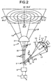
- the optical engine 1 includes a discharge lamp 10 serving as a light source (output of, for example, 35 watts), a reflector 11 reflecting a light L1 emitted from the discharge lamp 10, and a collimator lens 12 emitting a reflected light L2 from the reflector 11 as a parallel light L3.
- a discharge lamp 10 serving as a light source (output of, for example, 35 watts)
- a reflector 11 reflecting a light L1 emitted from the discharge lamp 10
- a collimator lens 12 emitting a reflected light L2 from the reflector 11 as a parallel light L3.
- the reflection surface 13 is formed out of a NURBS (Non-Uniform Rational B-splines) free-form surface (see Japanese Patent Application Laid-Open No. 2001-35215).
- the reflection surface 13 makes the reflected light L2 incident on an incident surface 14 of the collimator lens 12 in a luminous intensity distribution (light distribution) shown in Fig: 3 and Fig. 4.
- the luminous intensity distribution shown in Figs. 3 and 4 has a high luminous intensity (Illuminance) at a center and a low luminous intensity (illuminance) at a circumference.
- the luminous intensity distribution of the light incident on the incident surface 14 of the collimator lens 12 coincides with the luminous intensity distribution (light distribution) of a vehicle illumination, i.e., a luminous intensity distribution having a high luminous intensity (illuminance) at a center and a low luminous intensity (illuminance) at a circumference.
- the light L1 emitted from the discharge lamp 10 can be thereby effectively used.
- the reflection type digital light deflector 2 (see Japanese Patent Application Laid-Open Nos. 8-201708 and 11-231234) is referred to as "a micro mirror element group digital drive”, "a reflection optical modulator”, “spatial light modulator”, “an optical information processor”, “an optical switch”, or the like.
- the reflection type digital light deflector 2 includes a complementary metal-oxide semiconductor (CMOS) substrate (for a Static random access memory (SRAM) semiconductor) 20, a conductor 21 arranged on the CMOS substrate 20, a yoke 23 arranged on the conductor 21 through a torsion hinge 22 so as to be tiltable, and a micro mirror element 25 supported by the yoke 23 through a post 24.
- CMOS complementary metal-oxide semiconductor
- SRAM Static random access memory
- the reflection type digital light deflector 2 includes a mechanical function, an optical function, and an electric function integrated on one semiconductor chip.
- the CMOS substrate 20, which serves as a drive section includes an address transistor.
- the yoke 23, which serves as a movable section, includes a landing chip (spring chip, or a bouncing chip) 27.
- the reflection type digital light deflector 2 has many micro mirror elements 25 arranged in a tiltable manner.
- the reflection type digital light deflector 2 digitally switches over a tilt angle of each micro mirror element 25 between a first tilt angle and a second tilt angle and thereby digitally switches over a reflection direction of the parallel light L3 from the collimator lens 12 of the optical engine 1 between ON or a first reflection direction and OFF or a second reflection direction.
- the reflection type digital light deflector 2 performs a so-called high-speed light switching operation. A state of an orientation of each micro mirror element 25 will be explained in detail with reference to Fig. 8.
- the element 25 is in a horizontal state (neutral state) referred to as "horizontal state” as indicated by a dotted line. If the element 25 is turned on, the element 25 tilts from the horizontal state to a state (ON-state) indicated by a solid line or to a state (OFF-state) indicated by a one-dot chain line by an electrostatic attracting force, depending on an output of the CMOS substrate 20 to an address memory.
- the ON-state of the micro mirror element 25 indicated by the solid line is a state In which the micro mirror element 25 tilts at the first tilt angle + ⁇ (e.g., +10 degrees or +12 degrees) against the horizontal state.
- the micro mirror element 25 in this ON-state reflects the light L3 from the optical engine 1 in the ON or first reflection direction indicated by a solid-line arrow.
- a reflected light L4 indicated by this solid-line arrow is reflected at an angle 2 ⁇ against the incident light L3 toward the light irradiation unit 3 to thereby illuminate the road surface and the like.
- the reflected light L4 is an ON reflected light from the reflection type digital light deflector 2.
- the OFF-state of the micro mirror element 25 indicated by the one-dot chain line is a state in which the micro mirror element 25 tilts at the second tilt angle - ⁇ (e.g., -10 degrees or -12 degrees) against the horizontal state.
- the micro mirror element 25 in this OFF-state reflects the light L3 from the optical engine 1 in the OFF or second reflection direction indicated by a one-dot-chain-line arrow.
- a reflected light L5 indicated by the one-dot-chain-line arrow is reflected at an angle 6 ⁇ against the incident light L3 toward an optical absorber 26 and invalidated.
- the reflected light L5 is an OFF reflected light from the reflection type digital light deflector 2.
- the micro mirror element 25 in the horizontal state reflects the parallel light L3 from the optical engine 3 in a neutral or third reflection direction indicated by a dotted-line arrow.
- a reflected light L6 indicated by this dotted-line arrow is reflected at an angle 4 ⁇ against the incident light L3.
- the reflected light L6 is a reflected light (neutral reflected light) from the reflection type digital light deflector 2 when the element 25 is turned off.
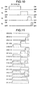
- ON and OFF control over the micro mirror elements 25 that is, switch over control over the tilt angles of the micro mirror elements 25 will next be explained in detail with reference to Figs. 9 and 10.
- the number of the total micro mirror elements 25 is (m+1) ⁇ (n+1).
- each micro mirror element 25 is turned on. If the control signal output from the controller 6 is "0”, each micro mirror element 25 is turned off.
- each micro mirror element 25 is controlled to be turned on or off according to the control signal "1" or "0" output from the controller 6. As a result, the micro mirror elements 25 are ON and OFF controlled.
- the control signal has four bits (T1, T2, T3, and T4), it is possible to precisely control the full-white color of the pixel having a luminous intensity of 100 percent at (1, 1, 1, 1), the full-black color of the pixel having a luminous intensity of zero percent at (0, 0, 0, 0), and the gray colors of the pixels at 14 gradations at (1, 0, 0, 0), (0, 1, 0, 0), (0, 0, 1, 0), (0, 0, 0, 1), ( 1, 1, 0, 0). (1, 0, 1, 0), (1, 0, 0, 1), (0, 1, 1, 0), (0, 1, 0, 1), (0, 0, 1. 1), (1, 1, 1, 0), (1, 0. 1, 1), (1, 1 0, 1), and (1, 1, 1, 0).
- the reflection type digital light deflector 2 controls the reflected light from each micro mirror element 25 to be turned on at a certain time to emit white and to be turned off at remaining time to emit black within a certain time while taking advantage of pulse width modulation according to gradation. If so, a person's vision senses the integrated white time as gradations (e.g., 0 to 255 gray scales for eight bits). Therefore, by controlling the ON-time per unit time, the reflection type digital light deflector 2 realizes a shade of light (luminous intensity difference and illuminance difference) in the light distribution pattern.
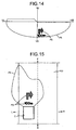
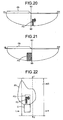
- the light irradiation unit 3 includes a divergent lens 30 that diverges the ON light L4 from the reflection type digital light deflector 2 and a condensing lens (projection lens) 31 that irradiates an emission light L7 from the divergent lens 30 on the road surface and the like as a irradiation light L8.
- the storage unit 4 is, for example, an internal storage unit (a magnetic disk such as a hard disk or a semiconductor storage unit such as a RAM or a ROM included in a computer or an external storage unit (an optical storage medium such as a CD-ROM or a semiconductor storage medium such as a memory card) exterior to the computer.
- the storage unit 4 stores digital data on a plurality of light distribution patterns.
- the digital data on the light distribution patterns stored in the storage unit 4 is divided in units of regions or countries in which the vehicle Is driven. By doing so, an optimum light distribution pattern for road conditions of the region or country where the vehicle is driven can be obtained without changing the overall vehicle lighting apparatus. Therefore, it is unnecessary to optically design or manufacture the vehicle lighting apparatus for each region or country, thereby reducing a manufacturing cost of the vehicle lighting apparatus accordingly.
- the optimum light distribution pattern for the road conditions of the region or country where the vehicle is driven means a light distribution pattern optimum for the road conditions in Japan or that for the road conditions in the US. That is, Japan is a left-hand side drive country and has many narrow crossing roads and many twisty roads. Therefore, the optimum light distribution pattern for the road conditions of left-hand traffic and many narrow crossing roads and twisty roads is the optimum light distribution pattern for the Japan's road conditions.
- the US is a right-hand side drive country and has many wide, straight roads. Therefore, the optimum light distribution pattern for the road conditions of right-hand traffic and many wide, straight roads is the optimum light distribution pattern for the US road conditions.
- the light distribution patterns include, for example, a light distribution pattern for a vehicle passing-by the other vehicle, that for a moving vehicle, that for general roads, that for highways, that for urban districts, that for suburbs, that for straight roads, that for curved roads, that for crossings, that for mountain paths, that for winding roads, that for rainy weather, that for foggy weather, and that for snowy weather.
- the digital data on the light distribution patterns is a digital data on a combination of the various light distribution patterns.
- the digital data includes "1. light distribution data for general road, straight road in high beam”, "2. light distribution data for general road, straight road in low beam”, “3. light distribution data for urban district, straight road in low beam”, “4. light distribution data for highway, straight read in low beam”, and “5. light distribution data for highway, curved road in low beam” as well as “6. light distribution data for highway, straight road in low beam”, “7. light distribution data for highway, curved road in high beam”, “8. light distribution data for general road, curved road in high beam”, “9. light distribution data for general road, curved road in low beam”, “10. light distribution data for general road and crossing", "11.
- the digital data on the light distribution patterns is data created by computer simulation so as to satisfy each standard in a light distribution design of the vehicle lighting apparatus.
- the digital data includes a plurality of binary-number bits for obtaining a plurality of luminous intensity gradations of many pixels, respectively.
- the vehicle lighting apparatus e.g., a headlamp, a fog lamp, a bent lamp (bending lamp), a curve lamp, or a side lamp
- the light distribution of the vehicle lighting apparatus is designed by the computer simulation so as to be able to ensure obtaining a predetermined light distribution pattern for each lamp or each function.
- the light distribution design is made based on an Ideal light distribution pattern that satisfies a predetermined light distribution pattern.
- This ideal light distribution pattern is a light distribution pattern obtained by digitally creating a light distribution pattern irradiated on a screen 10 meters head of the vehicle lighting apparatus so as to coincide with the light distribution pattern in which the lighting apparatus actually illuminates the road surface and the like.
- the ideal light distribution pattern thus digitally created by the computer represents a luminance intensity change in the form of a color distribution as an image visible to a person's eye, e.g., in 256-gradation scale for eight bits.
- the digital data on the light distribution pattern in this embodiment is digital data of eight bits having 786,432 pixels In a 256-gradation scale created based on ideal light distribution pattern. Namely, the digital data on the light distribution pattern is very digital data on the ideal light distribution pattern.
- one pixel of the digital data on the light distribution pattern corresponds to one of the micro mirror elements 25 of the reflection type digital light deflector 2.
- the reflection type digital light deflector 2 can finely control each of the 788,432 micro mirror elements 25 to emit a full-white coior, a full-black color, and gray colors at intermediate multiple gradations (e.g., 254 gradations if the data includes eight bits).
- each of the 786,432 micro mirror elements 25 of the reflection type digital light deflector 2 it is possible to finely, digitally control each of the 786,432 micro mirror elements 25 of the reflection type digital light deflector 2 to emit colors at 256 gradations based on the digital data on the light distribution pattern, i.e., the 256-gradation digital data on the 786,432 pixels of the ideal light distribution pattern.
- the digital display apparatus digitally forms the ideal light distribution pattern and irradiates light in the pattern. Therefore, the apparatus can illuminate the road surface and the like in the ideal light distribution pattern. That is, the digital display apparatus and the digital lighting apparatus according to the present invention digitally form the ideal light distribution pattern using the digital data on the ideal light distribution pattern, irradiate the light in the pattern as it is, and illuminate the road surface and the like.
- the surrounding environment detector 5 detects an environment surrounding the vehicle and outputs a detection signal.
- the surrounding environment detector 5 includes at least one of, for example, a steering sensor that detects one of or both of a steering angle and a steering speed of a steering wheel and that outputs a steering signal, a raindrop sensor that detects that it rains and that outputs a rain signal, a luminous intensity sensor that detects a brightness of surroundings of the vehicle and that outputs a luminous intensity signal, a turn sensor that detects an ON signal of a turn signal switch and that outputs a turn signal, a vehicle speed sensor that detects a vehicle speed and that outputs a vehicle speed signal, a wiper sensor that detects an ON signal of a wiper switch and that outputs a wiper signal, a radar that detects a reflected wave from a target in the surroundings of the vehicle and that outputs a radar signal, a humidity sensor that detects humidity of the surroundings of the vehicle and that outputs a humidity signal, a temperature sensor that detects
- the information acquisition unit 9 acquires information on the surroundings of the vehicle C and outputs an information signal.
- the information acquisition unit 9 includes at least one of, for example, a global positioning system (GPS) receiver (e.g., car navigation system) that receives a position information signal output from a GPS or a ground-based station (e.g., an electronic reference point), and an imaging device that images the information on the surroundings of the vehicle C and that outputs a signal (an image signal) based on an image.
- GPS global positioning system
- the information acquisition unit 9 can serve as the surrounding environment detector 5.
- the steering sensor has a plurality of slits provided equidistantly on a rotational body rotating while being interlocked with the steering of the steering wheel and a sensor such as a photo-interrupt sensor put between the slits on the rotational body.
- the steering sensor converts the steering angle to an electric signal based on the output of the sensor, detects a rotational direction and a position of the steering wheel, and outputs a detection signal as the steering signal to the controller 6.
- the raindrop sensor outputs an HI-level signal or an LO-level signal as the rain signal to the controller 6 when it rains or it does not rain, respectively.
- the luminous intensity sensor outputs an HI-level signal or an LO-level signal as the luminous intensity signal to the controller 6 when the brightness of the surroundings of the vehicle is equal to or higher than a predetermined brightness or equal to or lower than the predetermined brightness, respectively.
- the turn sensor outputs an Hi-level signal or an LO-level signal as the turn signal to the controller 6 when the turn signal switch is turned on or off, respectively.
- the vehicle speed sensor outputs the vehicle speed signal with a pulse changing according to the vehicle speed, to the controller 6.
- the wiper sensor outputs an HI-level signal or an LO-level signal as the wiper signal to the controller 6 when the wiper switch is turned on or off, respectively.
- the imaging device which has an image processing circuit (not shown), images the information on the surroundings of the vehicle and outputs the image signal to the image processing circuit.
- the image processing circuit processes the image signal and outputs an HI-level signal or an LO-level signal to the controller 6 based on whether an oncoming vehicle or a preceding vehicle is present, whether it is foggy, whether there is a crossing, and whether a road is a highway or a general road.
- the controller 6 includes an external signal input unit 60, a surrounding environment determination unit 61, a data selection unit 62, and a control signal output unit 63.
- the external signal input unit 60 inputs an external signal such as the detection signal of the surrounding environment detector 5 or the information signal of the information acquisition unit 9 and outputs the external signal as a processing signal to the surrounding environment determination unit 61.
- the surrounding environment determination unit 61 determines the surrounding environment of the vehicle based on the processing signal input from the external signal input unit 60 and outputs a determination signal to the data selection unit 62.
- the data selection unit 62 selects digital data on the optimum light distribution pattern for the surrounding environment of the vehicle from among digital data on a plurality of light distribution patterns stored in the storage unit 4 based on the determination signal input from the surrounding environment determination unit 61, and outputs the selected digital data to the control signal output unit 63.
- the control signal output unit 63 outputs a control signal for individually, digitally controlling switch over of the tilt angles of the micro mirror elements 25 to the reflection type digital light deflector 2 based on the digital data on the optimum light distribution pattern for the surrounding environment of the vehicle input from the data selection unit 62.
- the controller 6 employs a computer loaded on the vehicle.
- a computer that controls a car navigation system, a car audio system, a cellular phone, a control circuit section, an electrical control unit (ECU) and electronic control unit and the like are included.
- the controller 6 may employ a computer that is not loaded on the vehicle, e.g., a portable personal computer. With the portable personal computer, by storing user's desired digital data in the portable personal computer, even if the vehicle changes to the other vehicle, the user's desired light distribution pattern can be acquired at any time when the portable personal computer is connected to the changed vehicle.
- the controller 6 is controlled by an ordinary operating system (OS).
- OS ordinary operating system
- the controller 6 is constituted separately from the reflection type digital light deflector 2.
- the controller/computer 6 includes a central processing unit (CPU) 66.
- the CPU 66 includes the surrounding environment determination unit 61 and the data selection unit 62.
- the CPU 66 includes a main storage unit that stores a control program and a buffer storage unit which are not shown in Fig. 1.
- the external signal input unit 60 included in the controller 6 is, for example, an interface circuit.
- the control signal output unit 63 included in the controller 6 is, for example, a driver circuit.
- the surrounding environment determination unit 61 includes at least one of an oncoming vehicle/preceding vehicle determination unit, a highway/general road determination unit, an urban district determination unit (urban district/suburb determination unit), a crossing determination unit, a straight/curved road determination unit, a rain determination unit, a fog determination unit, a snow determination unit, an orientation determination unit, and a wait-at-stoplight determination unit.
- the oncoming vehicle/preceding vehicle determination unit determines whether an oncoming vehicle or a preceding vehicle is present based on the image signal obtained by imaging information on surroundings of the vehicle by the imaging device of the surrounding environment detector 5 and output from the imaging device, and outputs an oncoming vehicle/preceding vehicle presence signal or an oncoming vehicle/preceding vehicle absence signal.
- the highway/general road determination unit determines whether the road is a highway or a general road based on at least one of the image signal obtained by imaging the information on surroundings of the vehicle (e.g., a white line or a median strip drawn on the road surface) by the imaging device of the surrounding environment detector 5 and output from the imaging device, the vehicle speed single obtained by detecting the vehicle speed by the vehicle speed sensor of the surrounding environment detector 5 and output from the vehicle sensor, the position information signal output from the GPS or the ground-based station (e.g., electronic reference point) of the surrounding environment detector 5 and received by a GPS receiver (e.g., car navigation system), and the communication signal output from the ETC of the surrounding environment detector 5, and outputs a highway signal or a general road signal.
- the GPS or the ground-based station e.g., electronic reference point
- the urban district determination unit determines whether the vehicle is in the urban district based on at least one of the image signal obtained by imaging the information on surroundings of the vehicle by the imaging device of the surrounding environment detector 5 and output from the imaging device, the luminous intensity signal obtained by detecting the brightness of the surroundings of the vehicle by the luminous intensity sensor of the surrounding environment detector 5 and output from the luminous intensity sensor, and the position information signal output from the GPS or the like of the surrounding environment detector 5, and outputs a signal indicating that the vehicle is in the urban district or a signal indicating that the vehicle is not in the urban district (e.g., a signal indicating that the vehicle is in the suburbs),
- the crossing determination unit determines whether the vehicle is at a crossing based on at least one of the image signal obtained by imaging the information on surroundings of the vehicle (e,g., a white line or a median strip drawn on the road surface) by the imaging device of the surrounding environment detector 5 and output from the imaging device, the turn signal obtained by detecting the ON signal of the turn signal switch by the turn sensor of the surrounding environment detector 5 and output from the turn sensor, and the position information signal output from the GPS or the like of the surrounding environment detector 5, and outputs a signal indicating that the vehicle is at a crossing or a signal indicating that the vehicle is not at a crossing.
- the image signal obtained by imaging the information on surroundings of the vehicle (e,g., a white line or a median strip drawn on the road surface) by the imaging device of the surrounding environment detector 5 and output from the imaging device
- the turn signal obtained by detecting the ON signal of the turn signal switch by the turn sensor of the surrounding environment detector 5 and output from the turn sensor
- the straight/curved road determination unit determines whether the road is straight or curved based on at least one of the steering signal obtained by detecting one of or both of the steering angle and the steering speed of the steering wheel by the steering sensor of the surrounding environment detector 5 and output from the steering sensor, the vehicle speed obtained by detecting the vehicle speed by the vehicle speed sensor of the surrounding environment detector 5 and output from the vehicle speed sensor, the position information signal output from the GPS or the like of the surrounding environment detector 5, and the image signal obtained by imaging the information on surroundings of the vehicle (e.g., a curved white line drawn on the road surface) by the imaging device of the surrounding environment detector 5 and output from the imaging device, and outputs a straight signal or a curve signal.
- the steering signal obtained by detecting one of or both of the steering angle and the steering speed of the steering wheel by the steering sensor of the surrounding environment detector 5 and output from the steering sensor
- the vehicle speed obtained by detecting the vehicle speed by the vehicle speed sensor of the surrounding environment detector 5 and output from the vehicle speed sensor the position information signal output from the GPS or the like
- the rain determination unit determines whether it rains based on at least one of the rain signal obtained by detecting that it rains by the raindrop sensor of the surrounding environment detector 5 and output from the raindrop sensor, the wiper signal obtained by detecting the ON signal of the wiper switch by the wiper sensor of the surrounding environment detector 5 and output from the wiper sensor, and the image signal obtained by imaging the information on surroundings of the vehicle (e.g., a reflectance of the road surface depending on how wet the surface is) by the imaging device of the surrounding environment detector 5 and output from the imaging device, and outputs a signal indicating that it rains or a signal indicating that it does not rain.
- the image signal obtained by imaging the information on surroundings of the vehicle (e.g., a reflectance of the road surface depending on how wet the surface is) by the imaging device of the surrounding environment detector 5 and output from the imaging device, and outputs a signal indicating that it rains or a signal indicating that it does not rain.
- the fog determination unit determines whether it is foggy based on at least one of the image signal obtained by imaging the information on surroundings of the vehicle by the imaging device of the surrounding environment detector 5 and output from the imaging device, the radar signal obtained by detecting the reflected wave from the target in the surroundings of the vehicle by the radar of the surrounding environment detector 5 and output from the radar, the humidity signal obtained by detecting the humidity of the surroundings of the vehicle by the humidity sensor of the surrounding environment detector 5 and output from the humidity sensor, and the temperature signal obtained by detecting the temperature of the surroundings of the vehicle by the temperature sensor of the surrounding environment detector 5 and output from the temperature sensor, and outputs a signal indicating that it is foggy or a signal indicating that it is not foggy.
- the snow determination unit determines whether it snows based on at least one of the image signal obtained by imaging the information on surroundings of the vehicle by the imaging device of the surrounding environment detector 5 and output from the imaging device, the wiper signal obtained by detecting the ON signal of the wiper switch by the wiper sensor of the surrounding environment detector 5 and output from the wiper sensor, and the temperature signal obtained by detecting the temperature of the surroundings of the vehicle by the temperature sensor of the surrounding environment detector 5 and output from the temperature sensor, and outputs a signal indicating that it snows or a signal indicating that it does not snow.
- the orientation determination unit determines whether the orientation of the vehicle changes based on the orientation signal obtained by detecting the orientation of the vehicle by the orientation sensor of the surrounding environment detector 5 and output from the orientation sensor, and outputs an orientation change signal according to a variation of the orientation of the vehicle.
- the wait-at-stoplight determination unit determines whether the vehicle is waiting at a stoplight based on the vehicle speed signal obtained by detecting the vehicle speed by the vehicle speed sensor of the surrounding environment detector 5 and output from the vehicle speed sensor, the position information signal output from the GPS or the like of the surrounding environment detector 5, and the image signal obtained by imaging the information on surroundings of the vehicle by the imaging device of the surrounding environment detector 5 and output from the imaging device, and outputs a signal indicating that the vehicle is waiting at a stoplight or a signal indicating that the vehicle is not waiting at a stoplight.
- the surrounding environment determination unit 61 includes one determination unit or a plurality of determination units.
- the white line or the like drawn on the road surface and imaged by the imaging device of the surrounding environment detector 5 as the information on surroundings of the vehicle is prescribed by the Road Traffic Law. Therefore, this information can be used as high-quality information.
- the data selection unit 62 Includes a main data selection section and an interrupt data selection section.
- the main data selection section selects the digital data on the optimum light distribution pattern for the surrounding environment of the vehicle from among pieces of the digital data on the light distribution patterns stored in the storage unit 4 based on the determination signal from at least one of the oncoming vehicle/preceding vehicle determination unit, the highway/general road determination unit, the urban district determination unit, the crossing determination unit, the straight/curved road determination unit, the rain determination unit, the fog determination unit, and the snow determination unit.
- the interrupt data selection section halts and interrupts the selection of the main data selection section and selects the digital data on the optimum light distribution pattern for the vehicle waiting at a stoplight or the orientation of the vehicle from among pieces of digital data on the light distribution patterns stored in the storage unit 4.
- the information display unit 90 is mounted in the CPU 66 of the controller/computer 6 and connected to the external signal input unit 60 and the control signal output unit 63.
- the information display unit 90 controls the reflection type digital light deflector 2 and displays information P2 that uses a contrast between the ON reflected light L4 and the OFF reflected light L6 from the reflection type digital light deflector 2 in a predetermined light distribution pattern (the optimum light distribution pattern P5 for the surrounding environment of the vehicle) for illuminating the road surface and the like through the light irradiation unit 3 based on the information signal from the Information acquisition unit 9.
- the contrast information P2 includes, for example, a graphic, a symbol, a letter, a number, and the like. As shown in Figs. 14 and 15, the contrast Information P2 in this embodiment includes "an arrow curved to the right" and "a letter of '100m'" based on the position information signal output from the GPS or the like of the information acquisition unit 9. The contrast information P2 is displayed in the light distribution pattern for the vehicle passing-by the other vehicle (the optimum light distribution pattern P5 for the surrounding environment of the vehicle) for illuminating the road surface and the like RD.
- the contrast Information P2 is displayed within the following range.
- the contrast information P2 is displayed within about 17 meters ahead in the traveling direction of the vehicle C. Namely, in order to satisfy the driving task of the driver, preview for three seconds or more is required. If the vehicle C is running at 20 km/h or more (since the vehicle running at less than 20 km/h is considered a slow-moving vehicle, a necessary condition for the preview for three seconds or more is excluded), it is necessary for the lighting apparatus of the vehicle to illuminate at least about 17 meters ahead In the traveling direction of the vehicle C.
- a range A1 more than about 17 meters ahead in the traveling direction is a range for acquiring information on the field of view necessary for the driving task, e.g., the shape of the road and whether an obstacle is present.
- the display obstructs the driving task.
- the contrast information P2 Is displayed within about 14 meters ahead in the traveling direction of the vehicle C. Namely, if a preceding vehicle FC is present, the driver of the vehicle C generally tends to maintain distance to the preceding vehicle FC corresponding to about 2.5 seconds. The distance that corresponds to about 2.5 seconds corresponds to about 14 meters if the vehicle C is running at 20 km/h. If the contrast information P2 is displayed within a range A2 more than about 14 meters ahead in the traveling direction, the display of the contrast information P2 is obstructed by a tail end of the preceding vehicle FC. It is, therefore, preferable for traffic safety to display the contrast information P2 within about 14 meters ahead in the traveling direction of the vehicle C so as not to be obstructed by the tail end of the preceding vehicle FC.
- the contrast information P2 is displayed more than about 4 meters ahead in the traveling direction of the vehicle C. Namely, a body shape of the vehicle C causes a blind spot for the visibility of the driver toward the forward road surface. If the vehicle C is a normal sedan, the field of view from a driver's seat has a blind spot caused by the influence of the hood of the vehicle C.
- a height of the hood is 0.75 meters above the ground, a length of the hood from a driver's eye E P is 2 meters, and a height of the driver's eye E P is 1.1 meter above the ground, the range within about 4.3 meters or less ahead in the traveling direction of the vehicle C enters the blind spot of the field of view by the influence of the hood. For this reason, if the contrast information P2 is displayed within about 4 meters ahead in the traveling direction, the contrast information P2 enters the blind point caused by the hood. It is, therefore, preferable for traffic safety to display the contrast information P2 more than 4 meters ahead in the traveling direction of the vehicle C so as not to enter the blind spot caused by the hood.
- the contrast information P2 it is preferable for traffic safety to display the contrast information P2 within a range A3 that is about 4 to 14 meters ahead in the traveling direction of the vehicle C.
- the digital display apparatus is constituted so that the vehicle digital lighting assemblies (each of which includes the optical engine 1, the reflection type digital light deflector 2, and the light irradiation unit 3 or includes the reflection optical deflector 2 and the light irradiation unit 3) are respectively loaded on the left and the right in the front portion of the vehicle C at predetermined intervals.
- the vehicle digital lighting assemblies each of which includes the optical engine 1, the reflection type digital light deflector 2, and the light irradiation unit 3 or includes the reflection optical deflector 2 and the light irradiation unit 3
- the contrast information P2 is displayed from each of the left and right vehicle digital lighting assemblies, it is necessary to strictly calculate an irradiation position, an irradiation direction, a spacing between the left and right digital lighting apparatuses, and an attachment height of each of the left and right digital lighting apparatuses so that shapes of the contrast information P2 displayed from the left and right vehicle digital lighting assemblies do not deviate from each other. Nevertheless, because of attachment allowances of the left and right vehicle digital lighting assemblies or the like, the shapes of the contrast information P2 displayed from the left and right vehicle digital lighting assemblies often deviate from each other.
- the digital display apparatus in this embodiment therefore, displays the contrast information P2 by the following method.
- the reflection type digital light deflector 2 included in one of the left and right vehicle digital lighting assemblies irradiates and displays the information P2 formed by the OFF reflected light in the predetermined light distribution pattern P5 (e.g., the light distribution pattern P5 for the vehicle passing-by the other vehicle) for illuminating the road surface and the like RD through the light irradiation unit 3 under the following control of an information display unit 90.
- the predetermined light distribution pattern P5 e.g., the light distribution pattern P5 for the vehicle passing-by the other vehicle
- the other reflection type digital light deflector 2 included in one of the left and right vehicle digital lighting assemblies irradiates and displays a non-lighting portion PD formed by the OFF reflected light in the predetermined light distribution pattern P5 for illuminating the road surface and the like RD so as to surround the information P2 through the light irradiation unit 3 under the following control of the information display unit 90.
- the information P2 from one of the left and right vehicle digital lighting assemblies and the non-lighting portion PD from the other one of the left and right vehicle digital lighting assemblies are combined with each other, whereby the information P2 from one vehicle digital lighting assembly is located within a range of the non-lighting portion PD from the other assembly.
- the shapes of the contrast information P2 do not deviate from each other, as compared with an instance in which the information is displayed from the left and right vehicle digital lighting assemblies, respectively. Namely, the contrast information P2 is displayed in a clear contrast.
- the sub-algorithms are added to a main algorithm (see Fig. 13) for the control by the controller 6.
- this information display unit 90 calculates a polygon that is the shape of the contrast information P2 and a rectangle of the non-lighting portion PD from the information signal based on the following sub-algorithm, and controls the OFF reflected lights of the left and right reflection type digital light deflectors 2.
- the surrounding environment detector 5 detects the surrounding environment of the vehicle (e.g., a region condition for the region in which the vehicle is running, a road condition for the road on which the vehicle is running or a weather condition) and outputs a detection signal to the controller 6 (at S1). If the detection signal is input to the controller 6, then the interface circuit of the external signal input unit 60 inputs the external signal such as the detection signal from the surrounding environment detector 5, processes the input signal to a signal that can be handled by the controller 6, and outputs the processed signal to the surrounding environment determination unit 61 (at S2). If the processed signal is input to the surrounding environment determination unit 61, the surrounding environment determination unit 61 determines the surrounding environment of the vehicle based on the processed signal from the external signal input unit 60, and outputs a determination signal to the data selection unit 62 (at S3).
- the surrounding environment of the vehicle e.g., a region condition for the region in which the vehicle is running, a road condition for the road on which the vehicle is running or a weather condition
- the surrounding environment determination unit 61 executes the first determination step to the tenth determination step.
- the oncoming vehicle/preceding vehicle determination unit determines whether an oncoming vehicle or a preceding vehicle is present based on the image signal of the imaging device and outputs the oncoming vehicle/preceding vehicle presence signal or the oncoming vehicle/preceding vehicle absence signal.
- the highway/general road determination unit determines whether the road is a highway or a general road based on at least one of the image signal of the imaging device, the vehicle speed single of the vehicle speed sensor, the position information signal of the GPS, and the communication signal of the ETC, and outputs the highway signal or the general road signal.
- the urban district determination unit determines whether the vehicle is in the urban district based on at least one of the image signal of the imaging device, the luminous intensity signal of the luminous intensity sensor, and the position information signal of the GPS, and outputs the signal indicating that the vehicle is in the urban district or the signal indicating that the vehicle is not in the urban district.
- the crossing determination unit determines whether the vehicle is at a crossing based on at least one of the image signal of the imaging device, the turn signal of the turn sensor, and the position information signal of the GPS or the like, and outputs the signal indicating that the vehicle is at a crossing or the signal indicating that the vehicle is not at a crossing.
- the straight/curved road determination unit determines whether the road is straight or curved based on at least one of the steering signal of the steering sensor, the vehicle speed signal of the vehicle speed sensor, and the position information signal of the GPS, and the image signal of the imaging device, and outputs the straight signal or the curve signal.
- the rain determination unit determines whether it rains based on at least one of the rain signal of the raindrop sensor, the wiper signal of the wiper sensor, and the image signal of the imaging device, and outputs the signal indicating that it rains or the signal Indicating that it does not rain.
- the fog determination unit determines whether it is foggy based on at least one of the image signal of the imaging device, the radar signal of the radar, the humidity signal of the humidity sensor, and the temperature signal of the temperature sensor, and outputs the signal indicating that it is foggy or the signal indicating that it is not foggy.
- the snow determination unit determines whether it snows based on at least one of the image signal of the imaging device, the wiper signal of the wiper sensor, and the temperature signal of the temperature sensor, and outputs the signal indicating that it snows or the signal indicating that it does not snow.
- the orientation determination unit determines whether the orientation of the vehicle changes based on the orientation signal of the orientation sensor, and outputs the orientation change signal according to the variation of the orientation of the vehicle.
- the wait-at-stoplight determination unit determines whether the vehicle is waiting at a stoplight based on all of or one of the vehicle speed signal of the vehicle speed sensor, the position information signal of the GPS, and the image signal of the imaging device, and outputs the signal indicating that the vehicle waiting at a stoplight or the signal indicating that the vehicle is not waiting at a stoplight.
- the determination steps executed by the surrounding environment determination unit 61 may include at least one of the first to tenth determination steps or include the other determination step.
- the data selection unit 62 selects the digital data on the optimum light distribution pattern for the surrounding environment of the vehicle from among pieces of digital data on the light distribution patterns stored in the storage unit 4 based on the determination signal of each determination unit included in the surrounding environment determination unit 5 (at S4).
- the main data selection section selects the digital data on the optimum light distribution pattern for the surrounding environment of the vehicle from among pieces of digital data on the light distribution patterns stored in the storage unit 4 based on the determination signal from at least one of the oncoming vehicle/preceding vehicle determination unit, the highway/general road determination unit, the urban district determination unit, the crossing determination unit, the straight/curved road determination unit, the rain determination unit, the fog determination unit, and the snow determination unit included in the surrounding environment determination unit 61.
- the main data selection section selects "1. light distribution data for general road, straight road, and running vehicle" shown in Fig. 12. If the highway/general road determination unit determines that the road is a general road, the straight/curved road determination unit determines that the road is straight, and the oncoming vehicle/preceding vehicle determination unit determines that an oncoming vehicle/preceding vehicle is present, the main data selection section selects "2. light distribution data for general road, straight road, and vehicle passing-by the other vehicle" shown in Fig.
- the main data selection section selects "3. light distribution data for urban district, straight road, and vehicle passing-by the other vehicle" shown in Fig. 12. If the highway/general road determination unit determines that the road is a highway, the straight/curved road determination unit determines that the road Is straight, and the oncoming vehicle/preceding vehicle determination unit determines that an oncoming vehicle/preceding vehicle is present, the main data selection section selects "4, light distribution data for highway, straight road, and vehicle passing-by the other vehicle" shown In Fig. 12.
- the main data selection section selects "5. light distribution data for highway, curved road, and vehicle passing-by the other vehicle" shown in Fig. 12. If the highway/general road determination unit determines that the road is a highway, the straight/curved road determination unit determines that the road is straight, and the oncoming vehicle/preceding vehicle determination unit determines that no oncoming vehicle/preceding vehicle is present, the main data selection section selects "6. light distribution data for highway, straight road, and running vehicle".
- the main data selection section selects "7. light distribution data for highway, curved road, and running vehicle". If the highway/general road determination unit determines that the road is a general road, the straight/curved road determination unit determines that the road is curved, and the oncoming vehicle/preceding vehicle determination unit determines that no oncoming vehicle/preceding vehicle is present, the main data selection section selects "8, light distribution data for general road, curved road, and running vehicle".
- the main data selection section selects "9. light distribution data for general road, curved road, and vehicle passing-by the other vehicie". If the highway/general road determination unit determines that the road is a general road and the crossing determination unit determines that a crossing is present, the main data selection section selects "10. light distribution data for general road and crossing".
- the main data selection section selects "11. light distribution data for urban district, straight road, and running vehicle". If the urban district determination unit determines that the vehicle is in an urban district, the straight/curved road determination unit determines that the road is curved, and the oncoming vehicle/preceding vehicle determination unit determines that an oncoming vehicle/preceding vehicle is present, the main data selection section selects "12, light distribution data for urban district, curved road, and vehicle passing-by the other vehicle".
- the main data selection section selects "13. light distribution data for urban district, curved road, and running vehicle". If the urban district determination unit determines that the vehicle is in an urban district and the crossing determination unit determines that a crossing is present, the main data selection section selects "14. light distribution data for urban district and crossing". Examples of the light distribution data selected by the main data selection section include various pieces of light distribution data depending on a combination of selection by the main data selection section besides the "1. light distribution data for general road, straight road, and running vehicle" to the "14. light distribution data for urban district and crossing".
- the wait-at-stoplight determination unit of the surrounding environment determination unit 61 determines whether the vehicle is waiting at a stoplight or the orientation determination unit thereof determines whether the orientation of the vehicle changes. If so, the interrupt data selection section of the data selection unit 62 halts and interrupts the selection of the main data selection section and selects the digital data on the optimum light distribution pattern for the vehicle waiting at a stoplight or the orientation of the vehicle from among pieces of digital data on the light distribution patterns stored in the storage unit 4 based on the determination signal from the wait-at-stoplight determination unit or from the orientation determination unit. In other words, an interrupt routine performed by the interrupt data selection section is established against a main routine performed by the main data selection section. After this interrupt routine is completed, the main data selection section performs the main routine again.
- the driver circuit that serves as the control signal output unit 63 outputs the control signal for individually, digitally controlling switchover of the tilt angles of the micro mirror elements 25 to the reflection type digital light deflector 2 based on the digital data on the optimum light distribution pattern for the surrounding environment of the vehicle selected by the data selection unit 62 (at S5).
- the reflection type digital light deflector 2 controls ON and OFF switching of the many micro mirror elements 25 based on the control signal, i.e., the digital data on the optimum light distribution pattern for the surrounding environment of the vehicle.
- the digital display apparatus can automatically select the optimum light distribution pattern P5 for the surrounding environment of the vehicle and illuminate the road surface and the like in this selected optimum light distribution P5 pattern for the surrounding environment of the vehicle.
- this information display unit 90 calculates the polygon Q that is the shape of the contrast information P and the second rectangle S of the non-lighting portion PD from the Information signal based on the sub-algorithm, and outputs the calculation result to the left and right reflection type digital light deflectors 2 through the control signal output unit 63.
- one of the left and right reflection type digital light deflectors 2 irradiates and displays the information P formed by the OFF reflected light in the predetermined light distribution pattern P5 for illuminating the road surface and the like RD through the light irradiation unit 3 under the control of the information display unit 90.
- the other reflection type digital light deflector 2 irradiates and displays the non-lighting portion PD formed by the OFF reflected light in the predetermined light distribution pattern P5 for illuminating the road surface and the like RD so as to surround the contrast information P through the light irradiation unit 3 under the control of the information display unit 90.
- the contrast information P is displayed in the predetermined light distribution pattern P5 for illuminating the road surface and the like RD while the contrast information P is located within the non-lighting portion PD.
- the digital display apparatus can display the contrast information P in the predetermined light distribution pattern P5 for illuminating the road surface and the like RD by the information display unit 90. Therefore, the driver can drive the vehicle C based on the displayed information. Hence, the digital display apparatus is preferable for traffic safety.
- the digital display apparatus can automatically display the information on surroundings of the vehicle C in the predetermined light distribution pattern P5 for illuminating the road surface and the like RD as the contrast information P by the information acquisition unit 9. Therefore, the digital display apparatus according to the first embodiment allows the driver to instantly grasp the information on surroundings of the vehicle C from the automatically displayed contrast information P and to drive the vehicle C based on the automatically displayed contrast information P. Hence, the digital display apparatus is preferable for traffic safety.
- the digital display apparatus can display the contrast information P in the predetermined light distribution pattern P5 for illuminating the road surface and the like RD within the range of about 4 to 14 meters ahead in the traveling direction of the vehicle C. Therefore, it is possible to satisfy the driving task of the driver.
- the display of the contrast information P is not obstructed by the tall end of the preceding vehicle FC and the contrast information P does not enter the blind spot of the field of view caused by the hood.
- the apparatus is preferable for traffic safety.
- one of the left and right reflection type digital light deflectors 2 irradiates and displays the information P2 formed by the OFF reflected light in the predetermined light distribution pattern P5 for illuminating the road surface and the like RD through the light irradiation unit 3 under the control of the information display unit 90.
- the other reflection type digital light deflector 2 irradiates and displays the non-lighting portion PD formed by the OFF reflected light in the predetermined light distribution pattern P5 for illuminating the road surface and the like RD so as to surround the contrast information P through the light irradiation unit 3 under the control of the information display unit 90.
- the digital display apparatus displays the contrast information P in the predetermined light distribution pattern P5 for illuminating the road surface and the like RD while the contrast information P is located within the non-lighting portion PD.
- the digital display apparatus can display the information using the contrast between the ON reflected light and the OFF reflected light without fading or deviation, as compared with the instance in which the information formed by the OFF reflected light is irradiated and displayed in the predetermined light distribution pattern from the left and right reflection type digital light deflectors through the light irradiation units, respectively.
- the digital display apparatus according to the first embodiment can display the polygon Q that is the shape of the contrast information P in a clear contrast and acquire clear information.
- the digital display apparatus is preferable for traffic safety.
- the digital display apparatus can automatically select the predetermined light distribution pattern P5 optimum for the surrounding environment of the vehicle and constantly illuminate the road surface and the like In the predetermined light distribution pattern P5 optimum for the surrounding environment of the vehicle. Hence, the digital display apparatus according to the first embodiment is preferable for traffic safety.
- the digital display apparatus particularly controls the reflection type digital light deflector 2 based on the digital data on the ideal light distribution pattern. Therefore, it is ensured that the predetermined light distribution pattern that is digitally controlled can be obtained.
- the digital display apparatus can digitally control the predetermined light distribution pattern P5 optimum for the surrounding environment of the vehicle directly using the digital data on the digitally created light distribution pattern. Therefore, it is ensured that the predetermined light distribution pattern P5 optimum for the surrounding environment of the vehicle without analogous irregularities can be obtained.
- the digital display apparatus can directly use the digital data on the light distribution pattern obtained in the light distribution design of the vehicle lighting apparatus as the digital data on the light distribution pattern for controlling the reflection type digital light deflector 2. Therefore, it is unnecessary to generate the digital data on the control light distribution pattern and manufacturing cost can be reduced, accordingly.
- the digital display apparatus can ensure detecting the surrounding environment of the vehicle by the surrounding environment detector 5. Therefore, it is further ensured that the light distribution pattern P5 suited for the surrounding environment of the vehicle can be obtained.
- the digital display apparatus can ensure controlling the reflection type digital light deflector 2 by the controller 6. Therefore, it is further ensured that the light distribution pattern P5 that is the optimum predetermined light distribution pattern P5 for the surrounding environment of the vehicle and that is free from 'analogous irregularities can be obtained.
- the digital display apparatus can ensure determining the surrounding environment of the vehicle by the surrounding environment determination unit 61. Therefore, it is further ensured that the light distribution pattern P5 suited for the surrounding environment of the vehicle can be obtained.
- the digital display apparatus can select the digital data on the optimum light distribution pattern for the surrounding environment of the vehicle from among the main data in the pieces of digital data on the light distribution patterns by the main data selection section. Therefore, it is further ensured that the light distribution pattern P5 optimum for the surrounding environment of the vehicle can be promptly selected.
- the interrupt data selection section can establish the interrupt control routines against the main control routine performed by the main data selection section. Therefore, the digital display apparatus according to the first embodiment can select the digital data on the optimum light distribution pattern for the surrounding environment of the vehicle more finely and control the data selection accurately and promptly,
- Fig. 24 and Fig. 25 are schematic diagrams for illustrating a digital display apparatus according to a first modification of the first embodiment.
- the same reference symbols as those in Fig. 1 to Fig. 23 denote the same constituent elements.
- the digital display apparatus digital display apparatus has a self-completive auto-leveling function that includes a charge coupled device (CCD) as an imaging device.
- the information display unit 90 displays an auto-leveling mark M1 as the contrast information P in the light distribution pattern P5 for the vehicle passing-by the other vehicle that is the optimum light distribution pattern for the surrounding environment of the vehicle.
- the CCD imaging device images the auto-leveling mark M1 and outputs an image signal to the controller 6 as the orientation signal.
- This CCD imaging device includes, for example, a CCD camera for visible light or infrared light.
- the controller 6 controls the reflection type digital light deflector 2 based on the orientation signal from the CCD imaging device and vertically moves a cut line CL of the light distribution pattern P5 for the vehicle passing-by the other vehicle.
- the auto-leveling mark M1 is shaped to have a tapered upper end. If the vehicle C is running on a horizontal road surface and the like RD, the auto-leveling mark M1 is shaped to be rectangular. If the vehicle C is running on an up-gradient road surface and the like RD, the auto-leveling mark M1 is shaped to have a tapered lower end.
- the CCD imaging device images the auto-leveling mark M1 and outputs the image signal to the controller 6 as the orientation signal.
- the controller 6 determines that the vehicle C is running on the down-gradient road surface and the like RD and moves the cut line CL of the light distribution pattern P5 for the vehicle passing-by the other vehicle in an arrow-U direction from a thick line or broken line to a one-dot chain line, i.e., upward or maintains the state indicated by the one-dot chain line if the auto-leveling mark M1 based on the orientation signal from the CCD imaging device is shaped to have the tapered upper end as shown in Fig. 25A.
- the controller 6 determines that the vehicle C is running on the horizontal road surface and the like RD and moves the cut line CL of the light distribution pattern P5 for the vehicle passing-by the other vehicle in an arrow-D direction from the one-dot chain line to the thick line, i,e., downward, moves the cut line CL of the light distribution pattern P5 in an arrow-U direction from the broken line to the thick line, i.e., upward or maintains the state indicated by the thick line if the auto-leveling mark M1 based on the orientation signal from the CCD imaging device is shaped to be rectangular as shown In Fig. 25B.
- the controller 6 determines that the vehicle C is running on the up-gradient road surface and the like RD and moves the cut line CL of the light distribution pattern P5 for the vehicle passing-by the other vehicle in the arrow-U direction from the thick line or the one-dot chain line to the broken line, i.e., downward or maintains the state indicated by the broken line if the auto-leveling mark M1 based on the orientation signal from the CCD imaging device is shaped to have the tapered lower end as shown in Fig. 25C.
- the digital display apparatus includes the CCD imaging device as the information acquisition unit 9.
- the digital display apparatus can thereby automatically, vertically move the cut line CL of the light distribution pattern P5 for the vehicle passing-by the other vehicle, i.e., perform so-called auto-leveling according to a vertical change in the orientation of the vehicle C.
- the digital display apparatus according to the first modification of the first embodiment grasps a deformation quantity of the auto-leveling mark M1 displayed In the light distribution pattern P5 for the vehicle passing-by the other vehicle as the variation of the orientation of the vehicle C. Therefore, it is unnecessary to provide the orientation sensor or the like that detects the orientation of the vehicle C and that outputs the orientation signal and manufacturing cost can be reduced, accordingly.
- the digital display apparatus according to the first modification of the first embodiment can dispense with the orientation sensor or the like and perform the auto-leveling by the digital lighting apparatus including the CCD imaging device that serves as the information acquisition unit 9 in a self-completive manner.
- Fig. 26 and Fig. 27 are schematic diagrams of a digital display apparatus according to a second modification of the first embodiment.
- the same reference symbols as those in Figs. 1 to 25C denote the same constituent elements.
- the information display unit 90 displays a vehicle width mark M2 that serves as the contrast information P in the predetermined light distribution pattern P5.
- the digital display apparatus according to the second modification of the first embodiment can grasp the vehicle width based on the vehicle width mark M2 and, therefore, the driver can grasp the information on surroundings of the vehicle C.
- the digital display apparatus according to the second modification of the first embodiment is preferable for traffic safety.
- the digital display apparatus can display such contrast information P as "WATCH DROPPINGS”, “RAILROAD CROSSING IS QUITE NEAR”. "WATCH STEEP CURVE”, or “WATCH DOWNWARD PATH” by the information signal of the information acquisition unit 9.
- Fig. 28 is a block diagram of a digital display apparatus according to a second embodiment of the present invention.
- the same reference symbols as those in Figs. 1 to 27 denote the same constituent elements.
- the digital display apparatus also serves as the digital lighting apparatus that illuminates the road surface and the like in the optimum light distribution pattern P5 for the surrounding environment of the vehicle.
- the digital lighting apparatus according to the second embodiment is a digital display apparatus separate from and independent of the digital lighting apparatus.
- the digital display apparatus automatically selects the optimum predetermined light distribution pattern P5 for the surrounding environment of the vehicle using the storage unit 4, the surrounding environment detector 5, the surrounding environment determination unit 61, the data selection unit 62, and the like.
- the digital lighting apparatus displays information on the road and the like through the reflection type digital light deflector 2 based on the information signal from the information acquisition unit 9 by the information display unit 90.
- the digital display apparatus can dispense with the storage unit 4, the surrounding environment detector 5, the surrounding environment determination unit 61, the data selection unit 62, and the like, the structure of the apparatus is simplified and manufacturing cost can be reduced, accordingly.
- the information e.g., the leveling mark M1 or the vehicle width mark M2
- the information can be irradiated and displayed on the road surface and the like.
Landscapes
- Engineering & Computer Science (AREA)
- Mechanical Engineering (AREA)
- Lighting Device Outwards From Vehicle And Optical Signal (AREA)
- Mechanical Light Control Or Optical Switches (AREA)
- Non-Portable Lighting Devices Or Systems Thereof (AREA)
Abstract
Description
Claims (14)
- A digital display apparatus for a vehicle, comprising:an optical engine (1) including a light source (10);a reflection type digital light deflector (2) that has a plurality of micro mirror elements (25) arranged to be respectively tiltable, that digitally switches a tilt angle of each of the micro mirror elements (25) between a first tilt angle and a second tilt angle to switch a reflection direction of a light from the optical engine (1) between a first reflection direction as an ON state and a second reflection direction as an OFF state;a light irradiation unit (3) that irradiates an ON state light reflected from the reflection type digital light deflector (2) on a road surface; andan information display unit (90) that controls the reflection type digital light deflector (2), and that displays information using a contrast between the ON state light and an OFF state light reflected from the reflection type digital light deflector (2) on the road surface via the light irradiation unit (3).
- A digital display apparatus for a vehicle, comprising:two optical engines (1), each of which includes a light source (10);two reflection type digital light deflectors (2), each of which has a plurality of micro mirror elements (25) arranged to be respectively tiltabfe, and digitally switches a tilt angle of each of the micro mirror elements (25) between a first tilt angle and a second tilt angle to switch a reflection direction of light from the optical engines (1) between a first reflection direction as an ON state and a second reflection direction as an OFF state;two light irradiation units (3), each of which irradiates an ON state light reflected from the reflection type digital light deflectors (2) on a road surface; andan information display unit (90) that controls the reflection type digital light deflectors (2), and that displays information using a contrast between the ON state light and an OFF state light reflected from the reflection type digital light deflectors (2) on the road surface via the light irradiation units (3), whereinone of the two reflection digital light deflectors (2) forms the information with the OFF state light under control of the information display unit (90),other of the two reflection digital light deflectors (2) forms a non-lighting portion with the OFF state light under control of the information display unit (90), andthe information display unit (90) displays the information and the non-lighting portion on the road surface via the light irradiation units (3) so that the non-lighting portion surrounds the information.
- The digital display apparatus according to claim 1 or 2, further comprising:an information acquisition unit (9) that acquires environmental information surrounding the vehicle, and that outputs the environmental information acquired as an information signal, whereinthe information display unit (90) controls the reflection type digital light deflectors (2) based on the information signal.
- The digital display apparatus according to claim 3, whereinthe information acquisition unit (9) is a global positioning system that outputs a position information signal.
- The digital display apparatus according to claim 1 or 2, whereinthe information is displayed on the road surface within about 17 meters ahead in a direction of traveling of the vehicle.
- The digital display apparatus according to claim 1 or 2, whereinthe information is displayed on the road surface within about 14 meters ahead in a direction of traveling of the vehicle.
- The digital display apparatus according to claim 1 or 2, whereinthe information is displayed on the road surface within a range from about 4 meters to about 17 meters ahead in a direction of traveling of the vehicle.
- The digital display apparatus according to any one of claims 1 to 7, whereinthe information includes at least one of a graphic, a symbol, a letter, a number, a leveling mark, and a mark that indicates width of the vehicle.
- A method of displaying information for a digital display apparatus for a vehicle, the digital display apparatus including two reflection type digital light deflectors, the method comprising:calculating a polygon that is a shape of information to be displayed;outputting the polygon to one of the reflection type digital light deflectors as a first control signal;calculating a first rectangle that surrounds the polygon;calculating a second rectangle that surrounds the first rectangle;outputting the second rectangle to other of the reflection type digital light deflectors as a second control signal; anddisplaying information that is formed by the one of the reflection type digital light deflectors based on the first control signal and a non-lighting portion formed by the other of the reflection type digital light deflectors based on the second control signal on a road surface so that the non-lighting portion surrounds the information.
- The method according to claim 9, further comprising:acquiring environmental information surrounding the vehicle; and outputting the environmental information acquired as an information signal, whereinthe information to be displayed is determined based on the information signal.
- The method according to claim 9, whereinthe information is displayed on the road surface within about 17 meters ahead in a direction of traveling of the vehicle.
- The method according to claim 9, whereinthe information is displayed on the road surface within about 14 meters ahead in a direction of traveling of the vehicle.
- The method according to claim 9, whereinthe information is displayed on the road surface within a range from about 4 meters to about 17 meters ahead in a direction of traveling of the vehicle.
- The method according to any one of claims 9 to 13, whereinthe information includes at least one of a graphic, a symbol, a letter, a number, a leveling mark, and a mark that Indicates width of the vehicle.
Applications Claiming Priority (2)
| Application Number | Priority Date | Filing Date | Title |
|---|---|---|---|
| JP2002382304A JP4059079B2 (en) | 2002-12-27 | 2002-12-27 | Digital lighting device for vehicle, digital display device for vehicle, and information display method |
| JP2002382304 | 2002-12-27 |
Publications (2)
| Publication Number | Publication Date |
|---|---|
| EP1433654A2 true EP1433654A2 (en) | 2004-06-30 |
| EP1433654A3 EP1433654A3 (en) | 2011-03-23 |
Family
ID=32463670
Family Applications (1)
| Application Number | Title | Priority Date | Filing Date |
|---|---|---|---|
| EP03029775A Withdrawn EP1433654A3 (en) | 2002-12-27 | 2003-12-23 | Digital display apparatus for vehicle and method of displaying information |
Country Status (3)
| Country | Link |
|---|---|
| US (1) | US7233311B2 (en) |
| EP (1) | EP1433654A3 (en) |
| JP (1) | JP4059079B2 (en) |
Cited By (12)
| Publication number | Priority date | Publication date | Assignee | Title |
|---|---|---|---|---|
| EP2843298A3 (en) * | 2013-08-30 | 2015-12-02 | SL Corporation | Head lamp for vehicle |
| EP2988060A4 (en) * | 2013-04-15 | 2016-11-30 | Koito Mfg Co Ltd | HEADLIGHT FOR ONE VEHICLE |
| FR3041066A1 (en) * | 2015-09-14 | 2017-03-17 | Valeo Vision | ILLUMINATING AND / OR SIGNALING SYSTEM COMPRISING A PROJECTION DEVICE SUITABLE FOR PROJECTING A SEGMENTED LIGHT BEAM |
| FR3042844A1 (en) * | 2015-09-14 | 2017-04-28 | Valeo Vision | LIGHTING SYSTEM FOR MOTOR VEHICLES |
| AT518724A1 (en) * | 2016-06-13 | 2017-12-15 | Zkw Group Gmbh | Vehicle headlight and method for generating a light distribution |
| FR3056486A1 (en) * | 2016-09-29 | 2018-03-30 | Valeo Vision | LIGHTING SYSTEM FOR MOTOR VEHICLE AND MOTOR VEHICLE |
| FR3056485A1 (en) * | 2016-09-29 | 2018-03-30 | Valeo Vision | LIGHTING SYSTEM FOR MOTOR VEHICLE AND MOTOR VEHICLE |
| FR3056680A1 (en) * | 2016-09-29 | 2018-03-30 | Valeo Vision | LIGHTING SYSTEM FOR MOTOR VEHICLE |
| EP3301500A1 (en) * | 2016-09-29 | 2018-04-04 | Valeo Vision | Lighting system of a motor vehicle and motor vehicle |
| FR3063796A1 (en) * | 2017-03-10 | 2018-09-14 | Valeo Vision | LIGHTING DEVICE FOR A LUMINOUS BEAM WITH A DAMED CENTRAL ZONE |
| EP2993390B1 (en) * | 2014-09-06 | 2020-06-17 | Audi Ag | Headlight for a motor vehicle and a motor vehicle |
| EP3115256B1 (en) * | 2015-07-10 | 2025-05-28 | Valeo Vision | Method for controlling a light beam and corresponding lighting system |
Families Citing this family (48)
| Publication number | Priority date | Publication date | Assignee | Title |
|---|---|---|---|---|
| JP4186923B2 (en) | 2004-12-17 | 2008-11-26 | 株式会社デンソー | Visibility improvement support device |
| US7195379B2 (en) * | 2005-01-03 | 2007-03-27 | Ford Global Technologies, Llc | Anti-blinding system for a vehicle |
| JP4466608B2 (en) * | 2006-05-18 | 2010-05-26 | 株式会社デンソー | Vehicle headlamp device |
| JP4720764B2 (en) * | 2006-11-16 | 2011-07-13 | 株式会社デンソー | Headlight control device |
| JP5262057B2 (en) * | 2006-11-17 | 2013-08-14 | 株式会社豊田中央研究所 | Irradiation device |
| JP4930315B2 (en) | 2007-01-19 | 2012-05-16 | 株式会社デンソー | In-vehicle information display device and light irradiation device used therefor |
| US8560124B2 (en) | 2007-07-13 | 2013-10-15 | Cummins Inc. | Idle control system and method for adaptive temperature control |
| US8078339B2 (en) * | 2007-07-13 | 2011-12-13 | Cummins Inc. | Circuit board with integrated connector |
| US8436902B2 (en) * | 2007-08-30 | 2013-05-07 | Valeo Schalter And Sensoren Gmbh | Method and system for weather condition detection with image-based road characterization |
| US8648544B2 (en) * | 2008-06-20 | 2014-02-11 | Panasonic Corporation | Illumination lighting apparatus, illumination apparatus, and illumination system |
| JP2010000957A (en) * | 2008-06-20 | 2010-01-07 | Koito Mfg Co Ltd | Headlight device for vehicle |
| JP5338176B2 (en) * | 2008-07-30 | 2013-11-13 | 株式会社豊田中央研究所 | Video display device |
| US8437913B2 (en) * | 2008-09-12 | 2013-05-07 | Ford Global Technologies | Steering pull compensation |
| JP5287121B2 (en) * | 2008-10-14 | 2013-09-11 | 株式会社豊田中央研究所 | Vehicle lighting device |
| WO2010144970A1 (en) * | 2009-06-19 | 2010-12-23 | Cohda Wireless Pty Ltd | Characterisation of a wireless communications link |
| US8498778B2 (en) | 2011-04-21 | 2013-07-30 | Continental Automotive Systems, Inc | Navigation system controlled turn signals |
| US9534756B2 (en) | 2012-04-03 | 2017-01-03 | Sharp Kabushiki Kaisha | Light-emitting device, floodlight, and vehicle headlight |
| JP6072448B2 (en) * | 2012-04-03 | 2017-02-01 | シャープ株式会社 | Light emitting device, floodlight, and vehicle headlamp |
| JP5761119B2 (en) * | 2012-05-17 | 2015-08-12 | 株式会社デンソー | In-vehicle lighting system |
| JP6319943B2 (en) * | 2013-03-28 | 2018-05-09 | 株式会社小糸製作所 | Vehicle lamp |
| JP6321932B2 (en) | 2013-09-24 | 2018-05-09 | 株式会社小糸製作所 | Vehicle headlamp |
| CN103672662B (en) * | 2013-12-04 | 2016-01-27 | 奇瑞汽车股份有限公司 | The anti-glare headlamp of a kind of vehicle low cost |
| JP6075331B2 (en) | 2014-06-13 | 2017-02-08 | トヨタ自動車株式会社 | Vehicle lighting device |
| JP6219784B2 (en) * | 2014-06-17 | 2017-10-25 | トヨタ自動車株式会社 | Vehicle headlamp device |
| JP6112072B2 (en) * | 2014-06-19 | 2017-04-12 | トヨタ自動車株式会社 | Vehicle lighting device |
| DE102015201764B4 (en) * | 2015-02-02 | 2018-04-05 | Volkswagen Aktiengesellschaft | Method and driver assistance system for generating a light distribution by a vehicle for outputting a driving instruction |
| CN110654306A (en) * | 2015-04-10 | 2020-01-07 | 麦克赛尔株式会社 | Vehicle with a steering wheel |
| FR3053010A1 (en) * | 2016-06-28 | 2017-12-29 | Valeo Vision | LIGHTING SYSTEM FOR A VEHICLE HAVING A MODULAR LUMINOUS INTENSITY LEVEL |
| KR101830662B1 (en) * | 2016-07-06 | 2018-02-21 | 엘지전자 주식회사 | Vehicle lamp and control metohd thereof |
| FR3055431B1 (en) * | 2016-09-01 | 2019-08-02 | Valeo Vision | DEVICE FOR PROJECTING A PIXELIZED IMAGE |
| JP6499632B2 (en) | 2016-12-07 | 2019-04-10 | スタンレー電気株式会社 | Vehicle lighting |
| JP6659659B2 (en) * | 2017-03-14 | 2020-03-04 | ヤマハ発動機株式会社 | Low beam color temperature changing headlight unit |
| JP6921619B2 (en) * | 2017-05-12 | 2021-08-18 | スタンレー電気株式会社 | Vehicle lighting and road surface drawing system |
| EP3401161B1 (en) | 2017-05-12 | 2022-02-09 | Stanley Electric Co., Ltd. | Road surface drawing system, lighting tool for vehicle and method of road surface drawing |
| EP3636490B1 (en) * | 2017-06-09 | 2023-05-24 | Koito Manufacturing Co., Ltd. | Vehicular lamp, and device and method for controlling same |
| JP6975566B2 (en) | 2017-07-14 | 2021-12-01 | スタンレー電気株式会社 | Vehicle lighting |
| AT519864B1 (en) * | 2017-08-10 | 2018-11-15 | Zkw Group Gmbh | Vehicle headlight and vehicle control |
| KR102470453B1 (en) * | 2017-12-29 | 2022-11-24 | 에스엘 주식회사 | Lamp for vehicle |
| JP7034718B2 (en) | 2018-01-04 | 2022-03-14 | スタンレー電気株式会社 | Display device for vehicles |
| CN110966563B (en) | 2018-09-28 | 2022-06-10 | 株式会社小糸制作所 | Vehicle headlamp |
| IT201800010490A1 (en) * | 2018-11-21 | 2020-05-21 | Prinoth Spa | TRACKED VEHICLE FOR SKI SLOPES AND METHOD OF DISPLAYING INFORMATION FOR SUCH TRACKED VEHICLE |
| US11480854B2 (en) * | 2018-12-26 | 2022-10-25 | Lumileds Llc | Vehicle side and rear exterior illumination and projection |
| JP7403482B2 (en) * | 2019-02-15 | 2023-12-22 | 株式会社小糸製作所 | Vehicle headlights and vehicle lights |
| WO2022244085A1 (en) * | 2021-05-18 | 2022-11-24 | 三菱電機株式会社 | Headlight control device, headlight control system, and headlight control method |
| CN114992581B (en) * | 2022-06-22 | 2023-06-02 | 重庆长安新能源汽车科技有限公司 | Lamp for vehicle and automobile |
| KR102789087B1 (en) * | 2022-11-24 | 2025-04-01 | 에스엘 주식회사 | Lamp for vehicle and control method of Lamp for vehicle |
| CN115951732B (en) * | 2022-12-20 | 2023-10-31 | 铭派技术开发有限公司 | Wisdom radar host computer temperature control system |
| CN116968625A (en) * | 2023-08-25 | 2023-10-31 | 长城汽车股份有限公司 | Vehicle light adjustment method, system, electronic device and vehicle |
Family Cites Families (14)
| Publication number | Priority date | Publication date | Assignee | Title |
|---|---|---|---|---|
| JPS6022541A (en) * | 1983-07-19 | 1985-02-05 | Honda Motor Co Ltd | Lighting apparatus for small-sized car |
| JPH0532117U (en) * | 1991-10-04 | 1993-04-27 | 三菱自動車工業株式会社 | Vehicle width confirmation light |
| JPH0798225A (en) * | 1993-09-29 | 1995-04-11 | Koito Mfg Co Ltd | Inclination angle measuring instrument |
| JP2861767B2 (en) * | 1993-12-22 | 1999-02-24 | トヨタ自動車株式会社 | Light distribution control device for headlamp |
| US5526951A (en) | 1994-09-30 | 1996-06-18 | Texas Instruments Incorporated | Fabrication method for digital micro-mirror devices using low temperature CVD |
| DE19530008B4 (en) | 1995-08-16 | 2005-02-03 | Automotive Lighting Reutlingen Gmbh | Illumination device for vehicles with a reflective deflection device |
| US6421165B2 (en) * | 1996-02-07 | 2002-07-16 | Light & Sound Design Ltd. | Programmable light beam shape altering device using programmable micromirrors |
| US6188933B1 (en) * | 1997-05-12 | 2001-02-13 | Light & Sound Design Ltd. | Electronically controlled stage lighting system |
| JPH11231234A (en) | 1998-02-12 | 1999-08-27 | Asahi Optical Co Ltd | Reflector |
| JP4395220B2 (en) | 1999-07-23 | 2010-01-06 | 市光工業株式会社 | Headlamp and method of manufacturing reflector in the headlamp |
| JP2001114012A (en) * | 1999-10-15 | 2001-04-24 | Koito Mfg Co Ltd | Lighting fixture device for vehicle |
| DE10034381C2 (en) * | 2000-07-14 | 2002-05-29 | Audi Ag | Information display device for vehicles |
| JP2004136838A (en) * | 2002-10-21 | 2004-05-13 | Toyota Industries Corp | Projection device and display device for vehicle |
| US6969183B2 (en) * | 2002-12-27 | 2005-11-29 | Ichikoh Industries, Ltd. | Digital lighting apparatus for vehicle, controller for digital lighting apparatus, and control program for digital lighting apparatus |
-
2002
- 2002-12-27 JP JP2002382304A patent/JP4059079B2/en not_active Expired - Fee Related
-
2003
- 2003-12-23 US US10/743,541 patent/US7233311B2/en not_active Expired - Fee Related
- 2003-12-23 EP EP03029775A patent/EP1433654A3/en not_active Withdrawn
Cited By (18)
| Publication number | Priority date | Publication date | Assignee | Title |
|---|---|---|---|---|
| EP2988060A4 (en) * | 2013-04-15 | 2016-11-30 | Koito Mfg Co Ltd | HEADLIGHT FOR ONE VEHICLE |
| EP2843298A3 (en) * | 2013-08-30 | 2015-12-02 | SL Corporation | Head lamp for vehicle |
| EP2993390B1 (en) * | 2014-09-06 | 2020-06-17 | Audi Ag | Headlight for a motor vehicle and a motor vehicle |
| EP3115256B1 (en) * | 2015-07-10 | 2025-05-28 | Valeo Vision | Method for controlling a light beam and corresponding lighting system |
| FR3041066A1 (en) * | 2015-09-14 | 2017-03-17 | Valeo Vision | ILLUMINATING AND / OR SIGNALING SYSTEM COMPRISING A PROJECTION DEVICE SUITABLE FOR PROJECTING A SEGMENTED LIGHT BEAM |
| FR3042844A1 (en) * | 2015-09-14 | 2017-04-28 | Valeo Vision | LIGHTING SYSTEM FOR MOTOR VEHICLES |
| AT518724A1 (en) * | 2016-06-13 | 2017-12-15 | Zkw Group Gmbh | Vehicle headlight and method for generating a light distribution |
| AT518724B1 (en) * | 2016-06-13 | 2018-02-15 | Zkw Group Gmbh | Vehicle headlight and method for generating a light distribution |
| FR3056680A1 (en) * | 2016-09-29 | 2018-03-30 | Valeo Vision | LIGHTING SYSTEM FOR MOTOR VEHICLE |
| EP3301500A1 (en) * | 2016-09-29 | 2018-04-04 | Valeo Vision | Lighting system of a motor vehicle and motor vehicle |
| CN107883336A (en) * | 2016-09-29 | 2018-04-06 | 法雷奥照明公司 | Motor vehicle lighting systems and motor vehicles |
| EP3305592A1 (en) * | 2016-09-29 | 2018-04-11 | Valeo Vision | Lighting system for a motor vehicle |
| US10203091B2 (en) | 2016-09-29 | 2019-02-12 | Valeo Vision | Motor vehicle lighting system and motor vehicle |
| FR3056485A1 (en) * | 2016-09-29 | 2018-03-30 | Valeo Vision | LIGHTING SYSTEM FOR MOTOR VEHICLE AND MOTOR VEHICLE |
| CN107883336B (en) * | 2016-09-29 | 2020-09-25 | 法雷奥照明公司 | Motor vehicle lighting system and motor vehicle |
| US11156334B2 (en) | 2016-09-29 | 2021-10-26 | Valeo Vision | Illumination system for an automotive vehicle |
| FR3056486A1 (en) * | 2016-09-29 | 2018-03-30 | Valeo Vision | LIGHTING SYSTEM FOR MOTOR VEHICLE AND MOTOR VEHICLE |
| FR3063796A1 (en) * | 2017-03-10 | 2018-09-14 | Valeo Vision | LIGHTING DEVICE FOR A LUMINOUS BEAM WITH A DAMED CENTRAL ZONE |
Also Published As
| Publication number | Publication date |
|---|---|
| JP2004210130A (en) | 2004-07-29 |
| US7233311B2 (en) | 2007-06-19 |
| US20040189447A1 (en) | 2004-09-30 |
| EP1433654A3 (en) | 2011-03-23 |
| JP4059079B2 (en) | 2008-03-12 |
Similar Documents
| Publication | Publication Date | Title |
|---|---|---|
| US7233311B2 (en) | Digital display apparatus for vehicle and method of displaying information | |
| US6969183B2 (en) | Digital lighting apparatus for vehicle, controller for digital lighting apparatus, and control program for digital lighting apparatus | |
| EP3858671B1 (en) | Illuminating lamp for vehicle | |
| CN100387461C (en) | Anti-glare headlight control | |
| CN110966563B (en) | Vehicle headlamp | |
| EP2965946B1 (en) | Vehicular lighting apparatus | |
| US6293686B1 (en) | Lighting device for vehicles | |
| US6817740B2 (en) | Vehicle headlamp apparatus | |
| EP2399777B1 (en) | Control device, vehicle headlamp, and vehicle headlamp system | |
| CN210637972U (en) | Vehicle headlamp | |
| JP4019939B2 (en) | VEHICLE DIGITAL LIGHTING DEVICE, ITS CONTROL DEVICE, AND CONTROL PROGRAM | |
| CN102365190A (en) | Method and device for illuminating lateral areas of a roadway | |
| CN107128240A (en) | The illuminator and its control method of vehicle, vehicle | |
| JP7265306B2 (en) | vehicle headlight | |
| JP7370805B2 (en) | Vehicle road surface drawing device. | |
| JP3982412B2 (en) | Digital lighting device for vehicles | |
| JP2004210128A (en) | Digital lighting system for vehicles | |
| JP4055578B2 (en) | Digital lighting device for vehicles | |
| JP2004210127A (en) | Digital lighting system for vehicles | |
| JP3982410B2 (en) | Digital lighting device for vehicles | |
| JP2023553740A (en) | How to adjust vehicle lighting and vehicles when passing through construction sites | |
| JP4969530B2 (en) | Road sign recognition device | |
| JP7481921B2 (en) | Vehicle headlights |
Legal Events
| Date | Code | Title | Description |
|---|---|---|---|
| PUAI | Public reference made under article 153(3) epc to a published international application that has entered the european phase |
Free format text: ORIGINAL CODE: 0009012 |
|
| AK | Designated contracting states |
Kind code of ref document: A2 Designated state(s): AT BE BG CH CY CZ DE DK EE ES FI FR GB GR HU IE IT LI LU MC NL PT RO SE SI SK TR |
|
| AX | Request for extension of the european patent |
Extension state: AL LT LV MK |
|
| PUAL | Search report despatched |
Free format text: ORIGINAL CODE: 0009013 |
|
| AK | Designated contracting states |
Kind code of ref document: A3 Designated state(s): AT BE BG CH CY CZ DE DK EE ES FI FR GB GR HU IE IT LI LU MC NL PT RO SE SI SK TR |
|
| AX | Request for extension of the european patent |
Extension state: AL LT LV MK |
|
| 17P | Request for examination filed |
Effective date: 20110526 |
|
| 17Q | First examination report despatched |
Effective date: 20110714 |
|
| AKX | Designation fees paid |
Designated state(s): DE FR GB |
|
| STAA | Information on the status of an ep patent application or granted ep patent |
Free format text: STATUS: THE APPLICATION IS DEEMED TO BE WITHDRAWN |
|
| 18D | Application deemed to be withdrawn |
Effective date: 20140701 |