JP2004210128A - Digital lighting system for vehicle - Google Patents
Digital lighting system for vehicle Download PDFInfo
- Publication number
- JP2004210128A JP2004210128A JP2002382302A JP2002382302A JP2004210128A JP 2004210128 A JP2004210128 A JP 2004210128A JP 2002382302 A JP2002382302 A JP 2002382302A JP 2002382302 A JP2002382302 A JP 2002382302A JP 2004210128 A JP2004210128 A JP 2004210128A
- Authority
- JP
- Japan
- Prior art keywords
- vehicle
- signal
- surrounding environment
- light distribution
- distribution pattern
- Prior art date
- Legal status (The legal status is an assumption and is not a legal conclusion. Google has not performed a legal analysis and makes no representation as to the accuracy of the status listed.)
- Pending
Links
Images


Abstract
Description
【0001】
【発明の属する技術分野】
この発明は、反射型デジタル光偏向装置を使用して所定の配光パターンで路面などを照明する車両用デジタル照明装置にかかるものである。特に、この発明は、ドライバー好みの配光パターンが得られ、交通安全上好ましい車両用デジタル照明装置に関するものである。
【0002】
なお、この明細書において、「路面など」とは、路面およびその路面上の人(歩行者など)や物(先行車や対向車や道路標識や建物など)などを言う。
【0003】
【従来の技術】
反射型デジタル光偏向装置を使用して所定の配光パターンで路面などを照明する車両用の照明装置は、従来からある(たとえば、特許文献1参照)。
【0004】
【特許文献1】
特開平9−104288号公報(段落番号「0007」〜「0018」)
【0005】
【発明が解決しようとする課題】
この発明は、前記の従来の技術の改良にかかるものであり、その目的とするところは、ドライバー好みの配光パターンが得られ、交通安全上好ましい車両用デジタル照明装置を提供することにある。
【0006】
【課題を解決するための手段】
上記の目的を達成するために、請求項1にかかる発明は、光源を有する光学エンジンと、多数個の極小ミラー素子がそれぞれ傾倒可能に配置されており、前記多数個の極小ミラー素子の傾倒角度を第1傾倒角度と第2傾倒角度とにデジタル的に切り替えて、前記光学エンジンからの光の反射方向をONの第1反射方向とOFFの第2反射方向とにデジタル的にスイッチングする反射型デジタル光偏向装置と、前記反射型デジタル光偏向装置からのONの反射光であって所定の配光パターンの光を路面などに照射する光照射装置と、複数の配光パターンのデジタルデータが記憶されている記憶装置と、入力信号に基づいて前記記憶装置に記憶されている複数の配光パターンのデジタルデータの中から所定の配光パターンのデジタルデータを選択し、この選択された所定の配光パターンのデジタルデータに基づいて前記多数個の極小ミラー素子の切替スイッチングをデジタル的に個々に制御する制御装置と、前記記憶装置に記憶されている複数の配光パターンのデジタルデータを変更することができるデータ変更装置と、を備えたことを特徴とする。
【0007】
この結果、請求項1にかかる発明は、配光パターンをドライバー好みに書き替えることができるので、ドライバー好みの配光パターンが得られることとなり、交通安全上好ましい。
【0008】
また、請求項2にかかる発明は、データ変更装置に、変更された配光パターンのデジタルデータを保存する保存装置を設けた、ことを特徴とする。
【0009】
この結果、請求項2にかかる発明は、この発明の車両用デジタル照明装置を起動することにより、常に、ドライバー好みの配光パターンが瞬時に得られる。
【0010】
また、請求項3にかかる発明は、所定の配光パターンを選択して選択信号を出力する配光パターン選択装置を備え、制御装置が、前記配光パターン選択装置からの入力信号に基づいて記憶装置に記憶されている複数の配光パターンのデジタルデータの中から所定の配光パターンのデジタルデータを選択し、この選択された所定の配光パターンのデジタルデータに基づいて多数個の極小ミラー素子の切替スイッチングをデジタル的に個々に制御する、ことを特徴とする。
【0011】
この結果、請求項3にかかる発明は、ドライバーが配光パターン選択装置を介して所定の配光パターンのデジタルデータを選択するので、その分、装置の構造が簡単となり、製造コストが安価となる。
【0012】
また、請求項4にかかる発明は、車両の周囲環境を検知して検知信号として出力する周囲環境検知装置を備え、前記制御装置が、前記周囲環境検知装置からの入力信号に基づいて車両の周囲環境を判断し、この判断に基づいて記憶装置に記憶されている複数の配光パターンのデジタルデータの中から車両の周囲環境に最適な所定の配光パターンのデジタルデータを選択し、この選択された車両の周囲環境に最適な所定の配光パターンのデジタルデータに基づいて多数個の極小ミラー素子の切替スイッチングをデジタル的に個々に制御する、ことを特徴とする。
【0013】
この結果、請求項4にかかる発明は、車両の周囲環境に最適な所定の配光パターンを自動的に選択し、この選択された車両の周囲環境に最適な所定の配光パターンで路面などを常時照明することができるので、交通安全上好ましい。
【0014】
また、請求項5にかかる発明は、周囲環境判断装置が、周囲環境検知装置の撮像装置の車両の周囲の情報を撮像して出力された画像信号から対向車・先行車の有無を判断して対向車・先行車有り信号または対向車・先行車無し信号を出力する対向車・先行車判断部、周囲環境検知装置の撮像装置の車両の周囲の情報を撮像して出力された画像信号、周囲環境検知装置の車速センサーの車速を検知して出力された車速信号、周囲環境検知装置のGPSなどから出力された位置情報信号、周囲環境検知装置のETCから出力された交信信号、のうち少なくとも1つの信号から高速道路・一般道路を判断して高速道路信号または一般道路信号を出力する高速道路・一般道路判断部、周囲環境検知装置の撮像装置の車両の周囲の情報を撮像して出力された画像信号、周囲環境検知装置の照度センサーの車両の周囲の明るさを検知して出力された照度信号、周囲環境検知装置のGPSなどから出力された位置情報信号、のうち少なくとも1つの信号から市街地であるか否かを判断して市街地である信号または市街地でない信号を出力する市街地判断部、周囲環境検知装置の撮像装置の車両の周囲の情報を撮像して出力された画像信号、周囲環境検知装置のターンセンサーのターンシグナルスイッチのON信号を検知して出力されたターン信号、周囲環境検知装置のGPSなどから出力された位置情報信号、のうち少なくとも1つの信号から交差点であるか否かを判断して交差点である信号または交差点でない信号を出力する交差点判断部、周囲環境検知装置の操舵センサーのハンドルの操舵角度およびまたは操舵速度を検知して出力された操舵信号および周囲環境検知装置の車速センサーの車速を検知して出力された車速信号、周囲環境検知装置のGPSなどから出力された位置情報信号、のうち少なくとも1つの信号から道路線形の直線・カーブを判断して直線信号またはカーブ信号を出力する直線・カーブ判断部、周囲環境検知装置の雨滴センサーの雨を検知して出力された雨信号および周囲環境検知装置のワイパーセンサーのワイパースイッチのON信号を検出して出力されたワイパー信号から雨であるか否かを判断して雨である信号または雨でない信号を出力する雨判断部、周囲環境検知装置の撮像装置の車両の周囲の情報を撮像して出力された画像信号、周囲環境検知装置のレーダーの車両の周囲の対象物からの反射波を検知して出力されたレーダー信号、周囲環境検知装置の湿度センサーの車両の周囲の湿度を検知して出力された湿度信号および周囲環境検知装置の温度センサーの車両の周囲の温度を検知して出力された温度信号、のうち少なくとも1つの信号から霧であるか否かを判断して霧である信号または霧でない信号を出力する霧判断部、周囲環境検知装置の撮像装置の車両の周囲の情報を撮像して出力された画像信号、周囲環境検知装置のワイパーセンサーのワイパースイッチのON信号を検出して出力されたワイパー信号および周囲環境検知装置の温度センサーの車両の周囲の温度を検知して出力された温度信号、のうち少なくとも1つの信号から雪であるか否かを判断して雪である信号または雪でない信号を出力する雪判断部、周囲環境検知装置の姿勢センサーの車体の姿勢を検知して出力された姿勢信号から車体の姿勢の変化を判断して車体の姿勢の変化量に応じた姿勢変化信号を出力する姿勢判断部、周囲環境検知装置の車速センサーの車速を検知して出力された車速信号と、周囲環境検知装置のGPSなどから出力された位置情報信号またはおよび周囲環境検知装置の撮像装置の車両の周囲の情報を撮像して出力された画像信号とから信号待ちであるか否かを判断して信号待ちである信号または信号待ちでない信号を出力する信号待ち判断部、のうち少なくとも1つから構成されており、前記周囲環境判断装置に、対向車・先行車判断部、高速道路・一般道路判断部、市街地判断部、交差点判断部、直線・カーブ判断部、雨判断部、霧判断部、雪判断部、姿勢判断部、信号待ち判断部の判断をキャンセルすることができるキャンセル装置を設けた、ことを特徴とする。
【0015】
この結果、請求項5にかかる発明は、ドライバーが不要と思われる周囲環境判断装置の判断をキャンセルすることができるので、ドライバーが必要と思われる周囲環境判断装置の判断が得られる。このために、請求項5にかかる発明は、ドライバー好みの車両の周囲環境に最適な配光パターンが得られることとなり、交通安全上好ましい。
【0016】
また、請求項6にかかる発明は、キャンセル装置に、判断をキャンセルされた判断部を保存する保存装置を設けた、ことを特徴とする。
【0017】
この結果、請求項6にかかる発明は、この発明の車両用デジタル照明システムを起動することにより、常に、ドライバー好みの車両の周囲環境に最適な配光パターンが瞬時に得られる。
【0018】
また、請求項7にかかる発明は、選択された配光パターンのデジタルデータを画像データに変換し、この画像データが画像として表示される表示装置を有する、ことを特徴とする。
【0019】
この結果、請求項7にかかる発明は、選択された所定の配光パターンが表示装置で表示されるので、選択された所定の配光パターンであって、実際に路面などを照明する所定の配光パターンを目視で確認することができる。また、請求項7にかかる発明は、ドライバーが、データ変更装置で配光パターンのデジタルデータを変更する際、また、キャンセル装置で不要と思われる周囲環境判断装置の判断をキャンセルする際に、さらに、保存装置で変更された配光パターンのデジタルデータやキャンセルされた判断を保存する際に、表示装置で目視で確認しながら操作することができる。
【0020】
【発明の実施の形態】
以下、この発明にかかる車両用デジタル照明装置の実施の形態の2例について添付図面を参照して説明する。なお、この実施の形態によりこの発明が限定されるものではない。
【0021】
図において、符号「U」は、ドライバー側から見た上側を示す。符号「D」は、ドライバー側から見た下側を示す。符号「L」は、ドライバー側から前方を見た場合の左側を示す。符号「R」は、ドライバー側から前方を見た場合の右側を示す。符号「HL−HR」は、スクリーン上の左右水平線のことを示す。符号「VU−VD」は、同じく、スクリーン上の上下垂直線を示す。
【0022】
(実施の形態1の構成の説明)
「全体構成の説明」
図1〜図12は、この発明にかかる車両用デジタル照明装置の実施の形態1を示す。この車両用デジタル照明装置は、車両の周囲環境に最適な配光パターンP5で路面などを照明するものであって、この例では、自動車用のヘッドランプである。
【0023】
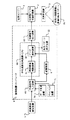
前記車両用デジタル照明装置は、図1に示すように、光学エンジン1と、反射型デジタル光偏向装置2と、光照射装置3と、記憶装置4と、周囲環境検知装置5と、制御装置6とを備えるものである。
【0024】
「光学エンジンの説明」
前記光学エンジン1は、図2に示すように、光源としての放電灯10(出力がたとえば35W)と、前記放電灯10からの光L1を反射させるリフレクタ11と、前記リフレクタ11からの反射光L2を平行光L3として出射させるコリメータレンズ(平行化レンズ)12とを備える。
【0025】
前記リフレクタ11の内面には、アルミ蒸着や銀塗装などが施されていて反射面13が設けられている。この反射面13は、NURBSの自由曲面(特開2001−35215号公報を参照)から形成されている反射面であって、反射光L2を前記コリメータレンズ12の入射面14に、図2(B)および(C)に示す配光分布で入射させるものである。図2(B)および(C)に示す配光分布は、中央における光度(照度)が高く、周囲における光度(照度)が低い配光分布をなすものであるから、車両用の照明の配光分布、すなわち、中央における光度(照度)が高く、周囲における光度(照度)が低い配光分布に一致するので、放電灯10からの光L1を有効に利用することができる。
【0026】
「反射型デジタル光偏向装置の説明」
前記反射型デジタル光偏向装置2(特開平8−201708号公報、特開平11−231234号公報を参照)は、極小ミラー素子群デジタル駆動装置、または、反射型光学変調素子、または、空間光変調器、または、光情報処理素子、または、光スイッチなどと称されている。
【0027】
前記反射型デジタル光偏向装置2は、図3〜図8に示すように、CMOS基板(SRAMメモリ半導体)20と、前記CMOS基板20上に配置された導体21と、前記導体21上にトーションヒンジ22を介して傾倒可能に配置されたヨーク23と、前記ヨーク23にポスト24を介して支持された極小ミラー素子25とから構成されている。すなわち、前記反射型デジタル光偏向装置2は、1個の半導体チップ上に機械的機能と、光学的機能と、電気的機能を集積したデバイスである。前記CMOS基板20は、駆動部であって、アドレスようのトランジスターからなる。前記ヨーク23は、可動部であって、ランディングチップ(スプリングチップ、バウンシングチップ)27を有する。
【0028】
前記反射型デジタル光偏向装置2は、多数個の前記極小ミラー素子25がそれぞれ傾倒可能に配置されているものである。前記多数個の極小ミラー素子25の個数は、たとえば、720×480=345600個、または、800×600=480000個、または、1024×768=786432個、または、1280×1024=1310720個、または、任意の個数である。
【0029】
前記反射型デジタル光偏向装置2は、前記多数個の極小ミラー素子25の傾倒角度を第1傾倒角度と第2傾倒角度とにデジタル的に切り替えて、前記光学エンジン1のコリメータレンズ12からの平行光L3の反射方向をONの第1反射方向とOFFの第2反射方向とにデジタル的にスイッチングするものである。前記反射型デジタル光偏向装置2は、いわゆる、光の高速スイッチング動作を行うデバイスである。以下、前記極小ミラー素子25の姿勢状態について図6を参照して詳細に説明する。
【0030】
すなわち、無通電時において、前記極小ミラー素子25は、点線で示すフラットステイトと称される水平状態(ニュートラル状態)にある。通電時において、前記極小ミラー素子25は、CMOS基板20のアドレスメモリへの出力に応じて静電引力により、水平状態から、実線で示す状態(ONの状態)に、または、一点鎖線で示す状態(OFFの状態)に、それぞれ傾倒するものである。
【0031】
前記極小ミラー素子25の実線で示すONの状態は、第1傾倒角度+θ(たとえば、+10°または+12°など)に傾倒した状態であって、このONの状態においては、前記光学エンジン1からの光L3を実線矢印に示すONの第1反射方向に反射させる。この実線矢印で示されている反射光L4は、前記入射光L3に対して角度2θで前記光照射装置3側に反射して、路面などを照明する。
【0032】
また、前記極小ミラー素子25の一点鎖線で示すOFFの状態は、第2傾倒角度−θ(たとえば、−10°または−12°など)に傾倒した状態であって、このOFFの状態においては、前記光学エンジン1からの光L3を一点鎖線矢印に示すOFFの第2反射方向に反射させる。この一点鎖線矢印で示されている反射光L5は、前記入射光L3に対して角度6θで光アブソーバー26側に反射して、無効化される。
【0033】
さらに、水平状態にある極小ミラー素子25は、前記光学エンジン1からの平行光L3を点線矢印に示す第3反射方向に反射させる。この点線矢印で示されている反射光L6は、前記入射光L3に対して角度4θで反射している。
【0034】
前記反射型デジタル光偏向装置2は、前記制御装置6から出力される制御信号により、前記多数個の極小ミラー素子25を1個ずつ、光の全白色、全黒色、中間の多数諧調(たとえば、8ビットの場合、256−2=254階調)の灰色と、精細に制御することができる。以下、多数個の極小ミラー素子25のON、OFFの制御について図7を参照して詳細に説明する。
【0035】
すなわち、図7(A)に示すように、多数個の極小ミラー素子25を1個ずつをピクセルとして、多数個の極小ミラー素子25のうち、x方向のピクセル(極小ミラー素子25)の位置を、0、1、2、3、4……mとし、y方向のピクセル(極小ミラー素子25)の位置を、0、1、2……nとする。(m×n)個、たとえば、720×480=345600個、または、800×600=480000個、または、1024×768=786432個、または、1280×1024=1310720個、または、任意の個数が、極小ミラー素子25の総数個である。また、前記制御装置6から出力される制御信号が「1」のときには、極小ミラー素子25がONの状態となり、前記制御装置6から出力される制御信号が「0」のときには、極小ミラー素子25がOFFの状態となるものとする。
【0036】
前記(m×n)個の極小ミラー素子25を、(0,0)→(1,0)→(2,0)→(3,0)→…→(m,0)→(0,1)→(1,1)→(2,1)→(3,1)→…→(m,1)→(0,2)→(1,2)→(2,2)→(3,2)→…→(m,2)→…→(m,n)の順に走査しながら、前記制御装置6から出力される制御信号「1」または「0」により、1個ずつONまたはOFFに制御するものである。
【0037】
前記制御装置6から出力される制御信号「1」または「0」は、2進数のビットデータである。たとえば、図7(B)に示すように、4ビットの場合においては、24 =2×2×2×2=16となるので、光の全白色、全黒色、中間の16−2=14階調の灰色と、精細に制御することができる。すなわち、4ビット(T1、T2、T3、T4)においては、図8に示すように、(1、1、1、1)の光度100%の全白色と、(0、0、0、0)の光度0%の全黒色と、(1、0、0、0)、(0、1、0、0)、(0、0、1、0)、(0、0、0、1)、(1、1、0、0)、(1、0、1、0)、(1、0、0、1)、(0、1、1、0)、(0、1、0、1)、(0、0、1、1)、(1、1、1、0)、(1、0、1、1)、(1、1、0、1)、(1、1、1、0)の14階調の灰色と、精細に制御することができる。
【0038】
なお、8ビットの場合においては、28 =2×2×2×2×2×2×2×2=256となるので、光の全白色、全黒色、中間の256−2=254階調の灰色と、精細に制御することができる。
【0039】
以上のように、前記反射型デジタル光偏向装置2は、一定時間のうち、階調に応じたパルス幅変調の手法を利用して、極小ミラー素子25からの反射光をある時間ONの白とし、残りの時間OFFの黒とする。すると、人間の視覚は、白の時間が積分されて階調(たとえば、8ビットの場合は、0〜255のグレースケール)として知覚することとなる。このために、前記反射型デジタル光偏向装置2は、単位時間当たりのONの時間を制御することにより、配光パターンの光の濃淡(光度差、照度差)が実現される。
【0040】
「光照射装置の説明」
前記光照射装置3は、前記反射型デジタル光偏向装置2からのONの光L4を発散させる発散レンズ30と、前記発散レンズ30からの出射光L7を照射光L8として路面などに照射する集光レンズ(投影レンズ)31とから構成されている。
【0041】
「記憶装置の説明」
前記記憶装置4は、たとえば、コンピュータに内蔵された内部記憶装置(ハードディスクなどの磁気ディスク、または、RAM、ROMなどの半導体記憶手段)、または、コンピュータに対して外付けの外部記憶装置(CD−ROMなどの光学系記憶媒体、記憶カードなどの半導体系記憶媒体)である。前記記憶装置4には、複数の配光パターンのデジタルデータが記憶されている。
【0042】
前記記憶装置4に記憶されている前記複数の配光パターンのデジタルデータは、車両が走行する地域・国別にそれぞれ群単位でユニット化されている。これにより、配光パターンのデジタルデータを地域・国別ごとに変えるだけで、車両用の照明装置全体を変えることなく、車両が走行する地域・国の道路状況に最適な配光パターンが得られることとなる。このために、各地域・国別ごとに、車両用の照明装置の光学設計や製造が不要となり、その分、製造コストが安価となる。
【0043】
ここで、車両が走行する地域・国の道路状況に最適な配光パターンとは、たとえば、日本の道路状況は左側通行で狭い交差路や曲線路が多く、この日本の道路状況に最適な配光パターンを言い、また、アメリカの道路状況は右側通行で広大な直線路が多く、このアメリカの道路状況に最適な配光パターンを言う。また、配光パターンとしては、たとえば、すれ違い用配光パターン、走行用配光パターン、一般道路用配光パターン、高速道路用配光パターン、市街地用配光パターン、郊外用配光パターン、直線用配光パターン、カーブ用配光パターン、交差点用配光パターン、山道用配光パターン、ワインディングロード用配光パターン、雨用配光パターン、霧用配光パターン、雪用配光パターンなどなどがある。
【0044】
前記の配光パターンのデジタルデータは、前記の種々の配光パターンを組み合わせたデジタルデータである。たとえば、図9に示すように、「1.一般道路・直線・走行用配光データ」、「2.一般道路・直線・すれ違い用配光データ」、「3.市街地・直線・すれ違い用配光データ」、「4.高速道路・直線・すれ違い用配光データ」、「5.高速道路・カーブ・すれ違い用配光データ」、また、図示しない「6.高速道路・直線・走行用配光データ」、「7.高速道路・カーブ・走行用配光データ」、「8.一般道路・カーブ・走行用配光データ」、「9.一般道路・カーブ・すれ違い用配光データ」、「10.一般道路・交差点用配光データ」、「11.市街地・直線・走行用配光データ」、「12.市街地・カーブ・すれ違い用配光データ」、「13.市街地・カーブ・走行用配光データ」、「14.市街地・交差点用配光データ」などなどである。
【0045】
「配光パターンのデジタルデータの説明」
以下、図9に示す配光データ、すなわち、配光パターンのデジタルデータについて説明する。前記配光パターンのデジタルデータは、車両の照明装置の配光設計においてコンピュータシミュレーション手法により作成され、複数の光度諧調が得られる2進数の複数ビットのデジタルデータである。なお、図9において、配光パターンの格子模様の中央部の光度(照度)が、白色の周辺部の光度(照度)より高い。すなわち、各配光パターンは、各規格を満足する配光パターンである。また、図9において、符号CLは、カットラインである。
【0046】
車両用の照明装置、たとえば、ヘッドランプ、フォグランプ、ベントランプ、カーブランプ、サイドランプなどは、交通安全上、法規や規格などで定められた所定の配光パターンで路面などを照明することが必要かつ重要である。このために、車両用の照明装置においては、各ランプごとにまた各機能ごとに所定の配光パターンが確実に得られるように、コンピュータを使用したシミュレーション手法により、配光設計が行われている。
【0047】
前記の配光設計は、所定の配光パターンを満足する理想の配光パターンに基づいて行われる。この理想の配光パターンは、実際に路面などを照明する配光パターンと一致するように、車両用の照明装置から10m前方のスクリーン上に照射されたパターンをコンピュータでデジタル的に作成されたものである。このコンピュータでデジタル的に作成された理想の配光パターンは、照度変化を色の分布により、人の目で見えるイメージで、たとえば、8ビット256階調のスケールで、デジタル的に表されている。
【0048】
ここで、前記スクリーンの大きさを、図2に示すように、上下垂直線VU−VDに対して左右両側にそれぞれ51.2°とし、かつ、左右水平線HL−HRに対して上下両側にそれぞれ38.4°とする。一方、前記スクリーンの0.1°×0.1°を1画素とした場合、前記スクリーンは、1024×768=786432画素となる。また、前記反射型デジタル光偏向装置2の極小ミラー素子25の個数を、1024×768=786432個とする。これにより、前記反射型デジタル光偏向装置2の極小ミラー素子25の1個と、前記スクリーンの1画素とは、それぞれ対応することとなる。
【0049】
この結果、1024×768=786432個の極小ミラー素子を1個ずつコントロールすることにより、配光パターンの786432個の画素を1個ずつ精細にコントロールすることができる。また、前記反射型デジタル光偏向装置2は、786432個の極小ミラー素子を1個ずつ、光の全白、全黒、中間の多数諧調(たとえば、8ビットの場合、256階調)の灰と、精細にコントロールすることができる。
【0050】
このように、この実施の形態1にかかる車両用デジタル照明装置は、理想の配光パターンのデジタルデータ、すなわち、786432個の画素の256階調のデジタルデータに基づいて、前記反射型デジタル光偏向装置2の786432個の極小ミラー素子を、1個ずつ256階調デジタルコントロールすることにより、理想の配光パターンをデジタル的に形成して照射し、路面などを照明することができる。すなわち、この発明にかかる車両用デジタル照明装置装置は、前記の理想の配光パターンのデジタルデータをそのまま使用して、理想の配光パターンをそのままデジタル的に形成して照射し、路面などを照明するものである。
【0051】
「周囲環境検知装置の説明」
前記周囲環境検知装置5は、車両の周囲環境を検知して検知信号として出力するものである。前記周囲環境検知装置5は、たとえば、ハンドルの操舵角度およびまたは操舵速度を検知して操舵信号を出力する操舵センサーと、雨を検知して雨信号を出力する雨滴センサーと、車両の周囲の明るさを検知して照度信号を出力する照度センサーと、ターンシグナルスイッチのON信号を検知してターン信号を出力するターンセンサーと、車速を検知して車速信号を出力する車速センサーと、ワイパースイッチのON信号を検知してワイパー信号を出力するワイパーセンサーと、車両の周囲の情報を撮像して画像に基づく信号(画像信号)を出力する撮像装置と、車両の周囲の対象物からの反射波を検知してレーダー信号を出力するレーダーと、車両の周囲の湿度を検知して湿度信号を出力する湿度センサーと、車両の周囲の温度を検知して温度信号を出力する温度センサーと、ライトスイッチのON信号を検知してライト信号を出力するライトセンサーと、車体の姿勢を検知して姿勢信号を出力する姿勢センサーと、GPSや地上局(電子基準点など)から出力された位置情報信号を受信するGPSレシーバー(たとえば、カーナビゲーション)と、有料道路に入る際に交信信号を出力するETCと、などなどのうち少なくとも1つから構成されている。このように、前記周囲環境検知装置5は、1個のセンサー、または、複数個のセンサーから組み合わされている。
【0052】
前記操舵センサーは、ハンドル操舵に連動して回転する回転体に複数のスリットを等間隔で設け、前記回転体のスリットを挟んでフォトインタラプトなどのセンサーを設けたものであって、センサーの出力からハンドル角度を電気信号に変換してハンドルの回転方向・位置を検出して検出信号を前記制御装置6に出力するものである。前記雨滴センサーは、雨が降っているときにHIレベルの信号を、雨が降っていないときにLOレベルの信号をそれぞれ前記制御装置6に出力するものである。前記照度センサーは、車両の周囲の明るさがある値以上のときにHIレベルの信号を、ある値以下のときにLOレベルの信号をそれぞれ前記制御装置6に出力するものである。前記ターンセンサーは、ターンシグナルスイッチがONのときにHIレベルの信号を、ターンシグナルスイッチがOFFのときにLOレベルの信号をそれぞれ前記制御装置6に出力するものである。前記車速センサーは、車両の速さに応じてパルスが変化する車速信号を前記制御装置6に出力するものである。前記ワイパーセンサーは、ワイパースイッチがONのときにHIレベルの信号を、ワイパースイッチがOFFのときにLOレベルの信号をそれぞれ前記制御装置6に出力するものである。前記撮像装置は、画像処理回路(図示せず)を有し、車両の周囲の情報を撮像して画像信号を前記画像処理回路に出力し、前記画像処理回路が画像信号を処理して対向車・先行車の有無、霧の有無、交差点の有無、高速道路・一般道路の判断によりHIレベルの信号またはLOレベルの信号をそれぞれ前記制御装置6に出力するものである。
【0053】
「制御装置の説明」
前記制御装置6は、図1に示すように、前記周囲環境検知装置5の検知信号などの外部信号を入力して処理信号として出力する外部信号入力装置60と、前記外部信号入力装置60の処理信号に基づいて車両の周囲環境を判断して判断信号として出力する周囲環境判断装置61と、前記周囲環境判断装置61の判断信号に基づいて前記記憶装置4に記憶されている複数の配光パターンのデジタルデータの中から車両の周囲環境に最適な配光パターンのデジタルデータを選択するデータ選択装置62と、前記データ選択装置62により選択された車両の周囲環境に最適な配光パターンのデジタルデータに基づいて前記多数個の極小ミラー素子25の切替スイッチングをデジタル的に個々に制御する制御信号を前記反射型デジタル光偏向装置2に出力する制御信号出力装置63と、を有するものである。
【0054】
前記制御装置6は、車両に搭載されているコンピュータを使用する。前記コンピュータとしては、たとえば、カーナビゲーション、カーオーディオ、携帯電話などをコントロール(制御)するコンピュータを使用する。また、前記制御装置6は、車両に搭載されていないコンピュータ、たとえば、携帯型パソコンなどを使用する場合であっても良い。この場合においては、携帯型パソコンにユーザー好みのデジタルデータを記憶させておけば、車両が変わっても、変わった車両に携帯型パソコンを接続することにより、ユーザー好みの配光パターンがいつでも得られることとなる。前記制御装置6は、一般のオペレーティングシステム(OS)で制御されるものである。このように、前記制御装置6は、前記反射型デジタル光偏向装置2と別個の構成となる。
【0055】
図1に示すように、前記制御装置6(コンピュータ)には、中央演算処理装置・CPU66が実装されている。前記中央演算処理装置・CPU66は、前記周囲環境判断装置61と前記データ選択装置62とから構成されている。また、前記中央演算処理装置・CPU66には、図示されていないが、制御プログラムが格納された主記憶装置とバッファ記憶装置とが実装されている。
【0056】
前記制御装置6の外部信号入力装置60としては、たとえば、インターフェイス回路である。また、前記制御装置6の制御信号出力装置63としては、たとえば、ドライバー回路である。
【0057】
「周環境判断装置の説明」
前記周囲環境判断装置61は、図10に示すように、前記周囲環境検知装置5の撮像装置の車両の周囲の情報を撮像して出力された画像信号から対向車・先行車の有無を判断して対向車・先行車有り信号または対向車・先行車無し信号を出力する対向車・先行車判断部と、前記周囲環境検知装置5の撮像装置の車両の周囲の情報(たとえば、路面上に引かれた白線や中央分離帯など)を撮像して出力された画像信号、前記周囲環境検知装置5の車速センサーの車速を検知して出力された車速信号、前記周囲環境検知装置5のGPSや地上局(電子基準点など)から出力されてGPSレシーバー(たとえば、カーナビゲーション)で受信された位置情報信号(この明細書において、GPSなどから出力された位置情報信号と称する)、前記周囲環境検知装置5のETCから出力された交信信号、のうち少なくとも1つの信号から高速道路・一般道路を判断して高速道路信号または一般道路信号を出力する高速道路・一般道路判断部と、前記周囲環境検知装置5の撮像装置の車両の周囲の情報を撮像して出力された画像信号、前記周囲環境検知装置5の照度センサーの車両の周囲の明るさを検知して出力された照度信号、前記周囲環境検知装置5のGPSなどから出力された位置情報信号、のうち少なくとも1つの信号から市街地であるか否かを判断して市街地である信号または市街地でない信号(たとえば、郊外である信号)を出力する市街地判断部と、前記周囲環境検知装置5の撮像装置の車両の周囲の情報(たとえば、路面に引かれた交差点の白線など)を撮像して出力された画像信号、前記周囲環境検知装置5のターンセンサーのターンシグナルスイッチのON信号を検知して出力されたターン信号、前記周囲環境検知装置5のGPSなどから出力された位置情報信号、のうち少なくとも1つの信号から交差点であるか否かを判断して交差点である信号または交差点でない信号を出力する交差点判断部と、前記周囲環境検知装置5の操舵センサーのハンドルの操舵角度およびまたは操舵速度を検知して出力された操舵信号および前記周囲環境検知装置5の車速センサーの車速を検知して出力された車速信号、前記周囲環境検知装置5のGPSなどから出力された位置情報信号、前記周囲環境検知装置5の撮像装置の車両の周囲の情報(たとえば、路面に引かれた曲線状の白線など)を撮像して出力された画像信号、のうち少なくとも1つの信号から道路線形の直線・カーブを判断して直線信号またはカーブ信号を出力する直線・カーブ判断部と、前記周囲環境検知装置5の雨滴センサーの雨を検知して出力された雨信号および前記周囲環境検知装置5のワイパーセンサーのワイパースイッチのON信号を検出して出力されたワイパー信号、前記周囲環境検知装置5の撮像装置の車両の周囲の情報(たとえば、路面の雨の濡れ具合による反射率など)を撮像して出力された画像信号、のうち少なくとも1つの信号から雨であるか否かを判断して雨である信号または雨でない信号を出力する雨判断部と、前記周囲環境検知装置5の撮像装置の車両の周囲の情報を撮像して出力された画像信号、前記周囲環境検知装置5のレーダーの車両の周囲の対象物からの反射波を検知して出力されたレーダー信号、前記周囲環境検知装置5の湿度センサーの車両の周囲の湿度を検知して出力された湿度信号および前記周囲環境検知装置5の温度センサーの車両の周囲の温度を検知して出力された温度信号、のうち少なくとも1つの信号から霧であるか否かを判断して霧である信号または霧でない信号を出力する霧判断部と、前記周囲環境検知装置5の撮像装置の車両の周囲の情報を撮像して出力された画像信号、前記周囲環境検知装置5のワイパーセンサーのワイパースイッチのON信号を検出して出力されたワイパー信号および前記周囲環境検知装置5の温度センサーの車両の周囲の温度を検知して出力された温度信号、のうち少なくとも1つの信号から雪であるか否かを判断して雪である信号または雪でない信号を出力する雪判断部と、前記周囲環境検知装置5の姿勢センサーの車体の姿勢を検知して出力された姿勢信号から車体の姿勢の変化を判断して車体の姿勢の変化量に応じた姿勢変化信号を出力する姿勢判断部と、前記周囲環境検知装置5の車速センサーの車速を検知して出力された車速信号と、前記周囲環境検知装置5のGPSなどから出力された位置情報信号またはおよび前記周囲環境検知装置5の撮像装置の車両の周囲の情報を撮像して出力された画像信号とから信号待ちであるか否かを判断して信号待ちである信号または信号待ちでない信号を出力する信号待ち判断部と、などなどのうち少なくとも1つから構成されている。このように、前記周囲環境判断装置61は、1個の判断部、または、複数個の判断部から組み合わされている。なお、前記周囲環境検知装置5の撮像装置が車両の周囲の情報として撮像する路面に引かれた白線などは、道路交通法に規定されているので、高品質の情報として利用することができる。
【0058】
「データ選択装置の説明」
前記データ選択装置62は、前記周囲環境判断装置61の対向車・先行車判断部、高速道路・一般道路判断部、市街地判断部、交差点判断部、直線・カーブ判断部、雨判断部、霧判断部、雪判断部、のうち少なくとも1つの判断部からの判断信号に基づいて、前記記憶装置4に記憶されている複数の配光パターンのデジタルデータの中から車両の周囲環境に最適な配光パターンのデジタルデータを選択する主データ選択部と、前記周囲環境判断装置61の信号待ち判断部または姿勢判断部からの判断信号に基づいて、前記記憶装置4に記憶されている複数の配光パターンのデジタルデータの中から信号待ちまたは車体の姿勢に最適な配光パターンのデジタルデータを前記主データ選択部の選択を中止させて割り込んで選択する割り込みデータ選択部と、を有する。
【0059】
「データ変更装置の説明」
図1に示すように、前記制御装置6には、データ変更装置(手動エディタ)70が設けられている。このデータ変更装置70は、前記記憶装置4に記憶されている複数の配光パターンのデジタルデータを変更することができるものであって、前記外部信号入力装置60に接続されている。
【0060】
「キャンセル装置の説明」
図1に示すように、前記制御装置6の前記周囲環境判断装置61には、キャンセル装置71が設けられている。このキャンセル装置71は、前記周囲環境判断装置の対向車・先行車判断部、高速道路・一般道路判断部、市街地判断部、交差点判断部、直線・カーブ判断部、雨判断部、霧判断部、雪判断部、姿勢判断部、信号待ち判断部の判断をキャンセルすることができるものである。このキャンセル装置71は、前記外部信号入力装置60を介して前記周囲環境判断装置61に接続されている。
【0061】
「保存装置」
前記データ変更装置70および前記キャンセル装置71には、それぞれ保存装置が設けられている。この保存装置は、データ変更装置70で変更された配光パターンのデジタルデータを保存したり、また、キャンセル装置71でをキャンセルされた判断を保存したりするものである。この保存装置は、図示されていないが、前記中央演算処理装置・CPU66の記憶装置(メモリ)であって、変更された配光パターンのデジタルデータやキャンセルされた判断部の判断(判断プログラム)を前記メモリに登録・再生できるものである。
【0062】
「表示装置の説明」
図1に示すように、制御装置6には、表示装置72が設けられている。この表示装置72は、図11に示すように、たとえば、液晶ディスプレーなどからなり、前記データ選択装置62に接続されており、前記データ選択装置62で選択された配光パターンのデジタルデータを画像データに変換し、この画像データを画像として表示するものである。また、この表示装置72は、データ変更装置70で変更される配光パターンのデジタルデータの内容と、キャンセル装置71でキャンセルされる周囲環境判断装置の判断部の内容と、保存装置で保存される変更された配光パターンのデジタルデータの内容やキャンセルされた判断部の内容とを表示することができるものである。
【0063】
前記表示装置72は、前記データ変更装置70および前記キャンセル装置71および保存装置(図示せず)と共に、後記する配光パターン選択装置7を構成する。また、前記データ変更装置70および前記キャンセル装置71および保存装置(図示せず)は、図11に示すように、タッチパネル構造の操作部を備えるものである。
【0064】
(実施の形態1の作用の説明)
この実施の形態1にかかる車両用デジタル照明装置は、以上のごとき構成からなり、以下、その作用について図12を参照して説明する。
【0065】
まず、周囲環境検知装置5が車両の周囲の環境、たとえば、車両が走行している地区状況や道路状況また天候状況などを検知し、その検知信号を制御装置6に出力する(S1)。検知信号が制御装置6に入力されると、外部信号入力装置60のインターフェイス回路が、前記周囲環境検知装置5の各検知信号などの外部信号を入力し、制御装置6で扱える信号に処理し、その処理信号を周囲環境判断装置61に出力する(S2)。処理信号が周囲環境判断装置61に入力されると、周囲環境判断装置61が、前記外部信号入力装置60の処理信号に基づいて車両の周囲環境を判断し、その判断信号をデータ選択装置62に出力する(S3)。
【0066】
前記周囲環境判断装置61は、下記の第1判断ステップから第10判断ステップまでを実行する。すなわち、対向車・先行車判断部が、周囲環境検知装置5の撮像装置の車両の周囲の情報を撮像して出力された画像信号から対向車・先行車の有無を判断して対向車・先行車有り信号または対向車・先行車無し信号を出力する第1判断ステップ。高速道路・一般道路判断部が、周囲環境検知装置5の撮像装置の車両の周囲の情報を撮像して出力された画像信号、周囲環境検知装置5の車速センサーの車速を検知して出力された車速信号、周囲環境検知装置5のGPSなどから出力された位置情報信号、前記周囲環境検知装置5のETCから出力された交信信号、のうち少なくとも1つの信号から高速道路・一般道路を判断して高速道路信号または一般道路信号を出力する第2判断ステップ。市街地判断部が、周囲環境検知装置5の撮像装置の車両の周囲の情報を撮像して出力された画像信号、周囲環境検知装置5の照度センサーの車両の周囲の明るさを検知して出力された照度信号、前記周囲環境検知装置5のGPSなどから出力された位置情報信号、のうち少なくとも1つの信号から市街地であるか否かを判断して市街地である信号または市街地でない信号を出力する第3判断ステップ。交差点判断部が、周囲環境検知装置5の撮像装置の車両の周囲の情報を撮像して出力された画像信号、周囲環境検知装置5のターンセンサーのターンシグナルスイッチのON信号を検知して出力されたターン信号、周囲環境検知装置5のGPSなどから出力された位置情報信号、のうち少なくとも1つの信号から交差点であるか否かを判断して交差点である信号または交差点でない信号を出力する第4判断ステップ。直線・カーブ判断部が、周囲環境検知装置5の操舵センサーのハンドルの操舵角度およびまたは操舵速度を検知して出力された操舵信号および周囲環境検知装置5の車速センサーの車速を検知して出力された車速信号、周囲環境検知装置5のGPSなどから出力された位置情報信号、のうち少なくとも1つの信号から道路線形の直線・カーブを判断して直線信号またはカーブ信号を出力する第5判断ステップ。雨判断部が、周囲環境検知装置5の雨滴センサーの雨を検知して出力された雨信号および周囲環境検知装置5のワイパーセンサーのワイパースイッチのON信号を検出して出力されたワイパー信号から雨であるか否かを判断して雨である信号または雨でない信号を出力する第6判断ステップ。霧判断部が、周囲環境検知装置5の撮像装置の車両の周囲の情報を撮像して出力された画像信号、周囲環境検知装置5のレーダーの車両の周囲の対象物からの反射波を検知して出力されたレーダー信号、周囲環境検知装置5の湿度センサーの車両の周囲の湿度を検知して出力された湿度信号および周囲環境検知装置5の温度センサーの車両の周囲の温度を検知して出力された温度信号、のうち少なくとも1つの信号から霧であるか否かを判断して霧である信号または霧でない信号を出力する第7判断ステップ。雪判断部が、周囲環境検知装置5の撮像装置の車両の周囲の情報を撮像して出力された画像信号、周囲環境検知装置5のワイパーセンサーのワイパースイッチのON信号を検出して出力されたワイパー信号および周囲環境検知装置5の温度センサーの車両の周囲の温度を検知して出力された温度信号、のうち少なくとも1つの信号から雪であるか否かを判断して雪である信号または雪でない信号を出力する第8判断ステップ。姿勢判断部が、周囲環境検知装置5の姿勢センサーの車体の姿勢を検知して出力された姿勢信号から車体の姿勢の変化を判断して車体の姿勢の変化量に応じた姿勢変化信号を出力する第9判断ステップ。
信号待ち判断部が、周囲環境検知装置5の車速センサーの車速を検知して出力された車速信号と、周囲環境検知装置5のGPSなどから出力された位置情報信号またはおよび周囲環境検知装置5の撮像装置の車両の周囲の情報を撮像して出力された画像信号とから信号待ちであるか否かを判断して信号待ちである信号または信号待ちでない信号を出力する第10判断ステップである。なお、前記周囲環境判断装置61が実行する判断ステップは、前記第1判断ステップから前記第10判断ステップのうち少なくとも1つから構成されているものであっても良いし、他の判断ステップから構成されているものであっても良い。
【0067】
前記判断信号がデータ選択装置62に入力されると、図12に戻って、データ選択装置62が、周囲環境判断手段5の各判断部の判断信号に基づいて記憶装置4に記憶されている複数の配光パターンのデジタルデータの中から車両の周囲環境に最適な配光パターンのデジタルデータを選択する(S4)。データ選択装置62は、主データ選択部(図示せず)と、割り込みデータ選択部(図示せず)とから構成されている。データ選択装置62の主データ選択部が周囲環境判断装置61の対向車・先行車判断部、高速道路・一般道路判断部、市街地判断部、交差点判断部、直線・カーブ判断部、雨判断部、霧判断部、雪判断部、のうち少なくとも1つの判断部からの判断信号に基づいて、記憶装置4に記憶されている複数の配光パターンのデジタルデータの中から車両の周囲環境に最適な配光パターンのデジタルデータを選択する。
【0068】
たとえば、高速道路・一般道路判断部が一般道路と判断し、直線・カーブ判断部が直線と判断し、対向車・先行車判断部が対向車・先行車無しと判断すると、主データ選択部は、図9に示す「1.一般道路・直線・走行用配光データ」を選択する。高速道路・一般道路判断部が一般道路と判断し、直線・カーブ判断部が直線と判断し、対向車・先行車判断部が対向車・先行車有りと判断すると、主データ選択部は、図9に示す「2.一般道路・直線・すれ違い用配光データ」を選択する。市街地判断部が市街地であると判断し、直線・カーブ判断部が直線と判断し、対向車・先行車判断部が対向車・先行車有りと判断すると、主データ選択部は、図9に示す「3.市街地・直線・すれ違い用配光データ」を選択する。高速道路・一般道路判断部が高速道路と判断し、直線・カーブ判断部が直線と判断し、対向車・先行車判断部が対向車・先行車有りと判断すると、主データ選択部は、図9に示す「4.高速道路・直線・すれ違い用配光データ」を選択する。高速道路・一般道路判断部が高速道路と判断し、直線・カーブ判断部がカーブと判断し、対向車・先行車判断部が対向車・先行車有りと判断すると、主データ選択部は、図9に示す「5.高速道路・カーブ・すれ違い用配光データ」を選択する。高速道路・一般道路判断部が高速道路と判断し、直線・カーブ判断部が直線と判断し、対向車・先行車判断部が対向車・先行車無しと判断すると、主データ選択部は、「6.高速道路・直線・走行用配光データ」を選択する。高速道路・一般道路判断部が高速道路と判断し、直線・カーブ判断部がカーブと判断し、対向車・先行車判断部が対向車・先行車無しと判断すると、主データ選択部は、「7.高速道路・カーブ・走行用配光データ」を選択する。高速道路・一般道路判断部が一般道路と判断し、直線・カーブ判断部がカーブと判断し、対向車・先行車判断部が対向車・先行車無しと判断すると、主データ選択部は、「8.一般道路・カーブ・走行用配光データ」を選択する。高速道路・一般道路判断部が一般道路と判断し、直線・カーブ判断部がカーブと判断し、対向車・先行車判断部が対向車・先行車有りと判断すると、主データ選択部は、「9.一般道路・カーブ・すれ違い用配光データ」を選択する。高速道路・一般道路判断部が一般道路と判断し、交差点判断部が交差点であると判断すると、主データ選択部は、「10.一般道路・交差点用配光データ」を選択する。市街地判断部が市街地であると判断し、直線・カーブ判断部が直線と判断し、対向車・先行車判断部が対向車・先行車無しと判断すると、主データ選択部は、「11.市街地・直線・走行用配光データ」を選択する。市街地判断部が市街地であると判断し、直線・カーブ判断部がカーブと判断し、対向車・先行車判断部が対向車・先行車有りと判断すると、主データ選択部は、「12.市街地・カーブ・すれ違い用配光データ」を選択する。市街地判断部が市街地であると判断し、直線・カーブ判断部がカーブと判断し、対向車・先行車判断部が対向車・先行車無しと判断すると、主データ選択部は、「13.市街地・カーブ・走行用配光データ」を選択する。市街地判断部が市街地であると判断し、交差点判断部が交差点であると判断すると、主データ選択部は、「14.市街地・交差点用配光データ」を選択する。なお、前記主データ選択部が選択する配光データは、前記「1.一般道路・直線・走行用配光データ」から前記「14.市街地・交差点用配光データ」まで以外に、前記主データ選択部の選択の組み合わせにより、種々の配光データがある。
【0069】
ここで、データ選択装置62の主データ選択部により選択された配光データで路面などを照明しているときに、周囲環境判断装置61の信号待ち判断部が信号待ちであると判断したり、または、周囲環境判断装置61の姿勢判断部が車体の姿勢の変化を判断したりする。すると、データ選択装置62の割り込みデータ選択部が信号待ち判断部または姿勢判断部からの判断信号に基づいて記憶装置4に記憶されている複数の配光パターンのデジタルデータの中から信号待ちまたは車体の姿勢に最適な配光パターンのデジタルデータを、主データ選択部の選択を中止させて割り込んで選択する。すなわち、主データ選択部によるメインルーチンに対して、割り込みデータ選択部による割り込みルーチンが成立することとなる。なお、この割り込みルーチンが完了した後には、メインルーチンに戻る。
【0070】
データ選択装置62が周囲環境判断装置61の判断に基づいて車両の周囲環境に最適な配光パターンのデジタルデータを選択すると、図12に戻って、制御信号出力装置63のドライバー回路が、データ選択装置62により選択された車両の周囲環境に最適な配光パターンのデジタルデータに基づいて多数個の極小ミラー素子25の切替スイッチングをデジタル的に個々に制御する制御信号を反射型デジタル光偏向装置2に出力する(S5)。
【0071】
そして、制御装置6から制御信号が反射型デジタル光偏向装置2に出力されると、反射型デジタル光偏向装置2は、制御信号、すなわち、車両の周囲環境に最適な配光パターンのデジタルデータに基づいて、多数個の極小ミラー素子25のON、OFFのスイッチングを制御する。これにより、この実施の形態1にかかる車両用デジタル照明装置は、車両の周囲環境に最適な配光パターンP5を自動的に選択してこの選択された車両の周囲環境に最適な配光パターンP5で路面などを照明することができる。
【0072】
この実施の形態における車両用デジタル照明装置は、ドライバーがデータ変更装置70の図11に示すタッチパネルの操作部を操作することにより、配光パターンのデジタルデータを任意に変更することができる。たとえば、信号待ちの減光制御(信号待ちの開始から配光パターンの光度を0に徐々に減少させる制御)において、光度が所定値から0に減少されるまでの時間を任意に変更することができる。また、走行用配光パターンやすれ違い用配光パターンなどの形状や光度を任意変更することができる。なお、配光パターンの変更は、各規格を満足する範囲内において行われる。
【0073】
また、ドライバーがキャンセル装置の図11の示すタッチパネルの操作部を操作することにより、周囲環境判断装置61の判断をキャンセルすることができる。たとえば、対向車・先行車判断部の対向車や先行車の有無の判断により、すれ違い用のロービームと走行用のハイビームとに切り替えるものである。ところが、ドライバーが、対向車や先行車が無くとも、ハイビームに切り替える必要性が無いと感じる場合には、対向車・先行車判断部の判断をキャンセルすることができる。また、ドライバーが必要でないと思われる判断部の判断をキャンセルすることができる。
【0074】
さらに、ドライバーが保存装置の図11に示すタッチパネルの操作部を操作することにより、変更された配光パターンのデジタルデータやキャンセルされた判断部の判断を保存装置に保存させることができる。なお、前記データ変更装置70、前記キャンセル装置71、前記保存装置の操作は、表示装置72の表示を目視しながら、タッチパネルで行うことができる
【0075】
(実施の形態1の効果の説明)
この実施の形態1にかかる車両用デジタル照明装置は、以上のごとき構成からなり、以下、その効果について説明する。
【0076】
この実施の形態1にかかる車両用デジタル照明装置は、配光パターンをドライバー好みに書き替えることができ、また、判断部の判断をキャンセルすることができるので、ドライバー好みの配光パターンが得られることとなり、交通安全上好ましい。
【0077】
また、この実施の形態1にかかる車両用デジタル照明装置は、データ変更装置70やキャンセル装置71に、変更された配光パターンのデジタルデータやキャンセルされた判断を保存する保存装置を設けたので、この実施の形態1にかかる車両用デジタル照明装置を起動することにより、常に、ドライバー好みの配光パターンが瞬時に得られる。
【0078】
また、この実施の形態1にかかる車両用デジタル照明装置は、車両の周囲環境に最適な所定の配光パターンP5を自動的に選択し、この選択された車両の周囲環境に最適な所定の配光パターンP5で路面などを常時照明することができるので、交通安全上好ましい。
【0079】
また、この実施の形態1にかかる車両用デジタル照明装置は、選択された所定の配光パターンが表示装置72で表示されるので、選択された所定の配光パターンであって、実際に路面などを照明する所定の配光パターンを目視で確認することができる。また、ドライバーが、データ変更装置70で配光パターンのデジタルデータを変更する際、また、キャンセル装置71で不要と思われる周囲環境判断装置の判断をキャンセルする際に、さらに、保存装置で変更された配光パターンのデジタルデータやキャンセルされた判断を保存する際に、表示装置72で目視で確認しながら操作することができる。
【0080】
(実施の形態2の説明)
図13は、この発明にかかる車両用デジタル照明装置の実施の形態2を示す。
図中、図1〜図12と同符号は、同一のものを示す。
【0081】
前記の実施の形態1にかかる車両用デジタル照明装置が、車両の周囲環境に最適な所定の配光パターンP5を自動的に選択してその選択された所定の配光パターンP5で路面などを照明するものに対して、この実施の形態2にかかる車両用デジタル照明装置は、所定の配光パターンP7を選択してその選択された所定の配光パターンP7で路面などを照明するものである。
【0082】
すなわち、前記の実施の形態1にかかる車両用デジタル照明装置が、周囲環境検知装置5および周囲環境判断装置61などにより車両の周囲環境に最適な所定の配光パターンP5を自動的に選択するものに対して、この実施の形態2にかかる車両用デジタル照明装置は、配光パターン選択装置7によりドライバーが所定の配光パターンP7を選択するものである。
【0083】
前記配光パターン選択装置7は、制御装置6の外部信号入力信号装置60に接続されており、前記外部信号入力装置60は、中央演算処理装置・CPU66のデータ選択装置62に接続されている。前記配光パターン選択装置7は、ドライバーが路面などを照明する配光パターンを選択し、その選択に基づいた選択信号を制御装置6の外部信号入力信号装置60に出力するものである。前記配光パターン選択装置7は、図11に示すように、データ変更装置70およびキャンセル装置71および保存装置および表示装置72と一体構造をなす。
【0084】
この実施の形態2にかかる車両用デジタル照明装置は、以上のごとき構成からなり、以下、その作用効果について説明する。
【0085】
まず、ドライバーが、配光パターン選択装置7で路面などを照明する配光パターンを選択する。すると、配光パターン選択装置7が、ドライバーの選択に基づいた選択信号を外部信号入力信号装置60に出力する。この外部信号入力装置60のインターフェイス回路が、前記配光パターン選択装置7からの選択信号などの外部信号を入力し、制御装置6で扱える信号に処理し、その処理信号をデータ選択装置62に出力する。
【0086】
つぎに、データ選択装置62が、外部信号入力装置60を介した配光パターン選択装置7からの選択信号に基づいて記憶装置4に記憶されている複数の配光パターンのデジタルデータの中からドライバーが選択した配光パターンのデジタルデータを選択する。
【0087】
それから、制御信号出力装置63のドライバー回路が、データ選択装置62により選択された配光パターンのデジタルデータに基づいて多数個の極小ミラー素子25の切替スイッチングをデジタル的に個々に制御する制御信号を反射型デジタル光偏向装置2に出力する。
【0088】
そして、制御装置6から制御信号が反射型デジタル光偏向装置2に出力されると、反射型デジタル光偏向装置2は、制御信号、すなわち、ドライバーが選択した配光パターンのデジタルデータに基づいて、多数個の極小ミラー素子25のON、OFFのスイッチングを制御する。これにより、この実施の形態1にかかる車両用デジタル照明装置は、ドライバーが選択した配光パターンP7で路面などを照明することができる。たとえば、ドライバーが、一般道路・直線・走行用の配光パターンを配光パターン選択装置7で選択する。すると、データ選択装置62が記憶装置4から図9に示す「1.一般道路・直線・走行用配光データ」を選択し、この「1.一般道路・直線・走行用配光データ」に基づいて、反射型デジタル光偏向装置2が制御されて、ドライバーが選択した一般道路・直線・走行用の配光パターンで路面などを照明することができる。
【0089】
このように、この実施の形態2にかかる車両用デジタル照明装置は、前記の実施の形態1にかかる車両用デジタル照明装置とほぼ同様の作用効果を達成することができる。たとえば、配光パターンをドライバー好みに書き替えることができるので、ドライバー好みの配光パターンが得られることとなり、交通安全上好ましい。また、変更された配光パターンのデジタルデータを保存装置に保存することができるので、この実施の形態に2にかかる車両用デジタル照明装置を起動することにより、常に、ドライバー好みの配光パターンが瞬時に得られる。さらに、選択された所定の配光パターン、が表示装置72で表示され、ドライバーがデータ変更装置70で配光パターンのデジタルデータを変更する際、また、保存装置で変更された配光パターンのデジタルデータを保存する際に、表示装置72で目視で確認しながら操作することができる。なお、この実施の形態2にかかる車両用デジタル照明装置においては、ドライバーが配光パターン選択装置7により配光パターンを選択するものであるから、前記の実施の形態1にかかる車両用デジタル照明装置のキャンセル装置71が不要となる。その分、構造が簡単となり、製造コストが安価となる。
【0090】
特に、この実施の形態2にかかる車両用デジタル照明装置は、前記の実施の形態1にかかる車両用デジタル照明装置の周囲環境検知装置5および周環境判断装置61の作用を、ドライバーが代わって行うものであるから、周囲環境検知装置5および周環境判断装置61が不要であり、その分、製造コストが安価となる。
【0091】
なお、この発明にかかる配光パターンは、AFS(Adaptive Front lighting System、または、Advanced Front lighting System)のロジックをそのまま使用する。
【0092】
(実施の形態以外の例の説明)
なお、前記実施の形態1、2においては、ヘッドランプについて説明したが、この発明は、その他のランプ、たとえば、フォグランプ、ターンシグナルランプ、ブレーキランプ(特に、急ブレーキ対応型で、急ブレーキを後続車に知らせるためのブレーキのフラッシュランプ)など、または、それらの組み合わせのランプであっても良い。
【0093】
また、前記実施の形態1、2においては、車両用デジタル照明装置が車両の左右にそれぞれ搭載されている場合、左右の配光パターンはそれぞれ異なるが、左右の配光パターンをトータルすることにより、所定の配光パターンが得られるように、配光データは構成されている。
【0094】
また、前記実施の形態1、2においては、反射型デジタル光偏向装置2の極小ミラー素子25のアスペクト比が、720×480、または、800×600、または、1024×768、または、1280×1024であるが、この発明は、車両用の配光パターンに適したアスペクト比としても良い。
【0095】
また、前記実施の形態1、2においては、光学エンジン1の光源として放電灯2を使用したものであるが、この発明においては、放電灯2以外の光源、たとえば、白熱灯、ハロゲンランプ、タングステンランプ、LED、赤外LEDなどを使用しても良い。しかも、光源は、1個でなく、複数個使用しても良い。
【0096】
また、前記実施の形態1、2において、光学エンジン1と反射型デジタル光偏向装置2とのレイアウトは、図2以外のレイアウトでも良い。たとえば、トラックなどの場合には、横長のフラットなレイアウトとし、また、軽自動車の場合には、縦長の筒型のレイアウトとする。すなわち、最終的に反射型デジタル光偏向装置2から反射される反射光L4がデジタル的に制御されているので、光学エンジン1から反射型デジタル光偏向装置2までの中間の光のアナログ的なずれは、無視できる。このために、光学エンジン1を車体スペックに合わせて、縦、横、上、下、斜め、などのレイアウトを取ることができ、また、冷却効果のあるエアダクト付近にレイアウトしても良い。
【0097】
また、前記の実施の形態1、2においては、光学エンジン1のリフレクタ11と反射型デジタル光偏向装置2との間にコリメータレンズ12を介在させてものであるが、この発明においては、リフレクタ11からの反射光を反射型デジタル光偏向装置2に直接入射させても良い。この場合、レンズによる色の収差むらや光むらがないなどの効果が得られる。
【0098】
また、前記の実施の形態においては、記憶装置として、コンピュータに内蔵された内部記憶装置(ハードディスクなどの磁気ディスク、または、RAM、ROMなどの半導体記憶手段)、または、コンピュータに対して外付けの外部記憶装置(CD−ROMなどの光学系記憶媒体、記憶カードなどの半導体系記憶媒体)を使用するものである。ここで、記憶カードなどの半導体系記憶媒体(以下、記憶媒体と称する)を使用する場合は、記憶媒体に記憶されているデータ(配光パターンのデジタルデータ、調光用のデジタルデータ)を読み取るための読取装置を外部信号入力装置60に接続する。また、制御装置6の中央演算処理装置・CPU66に実装されているバッファ記憶装置を外部信号入力装置60とデータ選択装置62に接続する。これにより、記憶媒体に記憶されているデータを読取装置および外部信号入力装置60を介してバッファ記憶装置に読み込まれて記憶されることとなる。
【0099】
【発明の効果】
以上から明らかなように、この発明にかかる車両用デジタル照明装置(請求項1)によれば、配光パターンをドライバー好みに書き替えることができるので、ドライバー好みの配光パターンが得られることとなり、交通安全上好ましい。
【0100】
また、この発明にかかる車両用デジタル照明装置(請求項2)によれば、データ変更装置に、変更された配光パターンのデジタルデータを保存する保存装置を設けたので、この発明の車両用デジタル照明装置を起動することにより、常に、ドライバー好みの配光パターンが瞬時に得られる。
【0101】
また、この発明にかかる車両用デジタル照明装置(請求項3)によれば、ドライバーが配光パターン選択装置を介して所定の配光パターンのデジタルデータを選択するので、その分、装置の構造が簡単となり、製造コストが安価となる。
【0102】
また、この発明にかかる車両用デジタル照明装置(請求項4)によれば、車両の周囲環境に最適な所定の配光パターンを自動的に選択し、この選択された車両の周囲環境に最適な所定の配光パターンで路面などを常時照明することができるので、交通安全上好ましい。
【0103】
また、この発明にかかる車両用デジタル照明装置(請求項5)によれば、ドライバーが不要と思われる周囲環境判断装置の判断をキャンセルすることができるので、ドライバーが必要と思われる周囲環境判断装置の判断が得られる。このために、この発明にかかる車両用デジタル照明装置(請求項5)は、ドライバー好みの車両の周囲環境に最適な配光パターンが得られることとなり、交通安全上好ましい。
【0104】
また、この発明にかかる車両用デジタル照明装置(請求項6)によれば、キャンセル装置に、判断をキャンセルされた判断部を保存する保存装置を設けたので、この発明の車両用デジタル照明システムを起動することにより、常に、ドライバー好みの車両の周囲環境に最適な配光パターンが瞬時に得られる。
【0105】
また、この発明にかかる車両用デジタル照明装置(請求項7)によれば、選択された所定の配光パターンが表示装置で表示されるので、選択された所定の配光パターンであって、実際に路面などを照明する所定の配光パターンを目視で確認することができる。また、この発明にかかる車両用デジタル照明装置(請求項7)は、ドライバーが、データ変更装置で配光パターンのデジタルデータを変更する際、また、キャンセル装置で不要と思われる周囲環境判断装置の判断をキャンセルする際に、さらに、保存装置で変更された配光パターンのデジタルデータやキャンセルされた判断を保存する際に、表示装置で目視で確認しながら操作することができる。
【図面の簡単な説明】
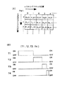
【図1】この発明にかかる車両用デジタル照明装置の実施の形態1を示す全体構成の機能ブロック図である。
【図2】(A)は、同じく、光学エンジンおよび光照射装置を示す説明図、(B)は(A)におけるB−B線矢視の光度分布を示す説明図、(C)は、同じく、(B)におけるC−C線矢視の高度分布を示す説明図である。
【図3】同じく、反射型デジタル光偏向装置を示す斜視図である。
【図4】同じく、反射型デジタル光偏向装置の構成を示す一部拡大斜視図である。
【図5】同じく、反射型デジタル光偏向装置の構成を示す一部拡大分解斜視図である。
【図6】同じく、反射型デジタル光偏向装置の作用を示す説明図である。
【図7】(A)は、同じく、反射型デジタル光偏向装置のピクセルの位置を示す説明図、
(B)は、同じく、反射型デジタル光偏向装置のピクセルの制御を示す説明図である。
【図8】同じく、4ビットにおける16階調の制御を示す説明図である。
【図9】同じく、配光データとその模式図の一部を示す説明図である。
【図10】同じく、周囲環境判断装備の一部を示すブロック図である。
【図11】同じく、配光パターン選択装置、データ変更装置、キャンセル装置、保存装置、表示装置を示す説明図である。
【図12】同じく、システムの作用を示すフローチャートである。
【図13】この発明にかかる車両用デジタル照明装置の実施の形態2を示す全体構成の機能ブロック図である。
【符号の説明】
U 上
D 下
L 左
R 右
VU−VD スクリーンの上下の垂直線
HL−HR スクリーンの左右の水平線
L1 放電灯10からの光
L2 リフレクタ11からの反射光
L3 コリメータレンズ12からの平行光
L4 反射型デジタル光偏向装置2からのONの反射光
L5 反射型デジタル光偏向装置2からのOFFの反射光
L6 反射型デジタル光偏向装置2からの無通電時の反射光
L7 発散レンズ30からの出射光
L8 集光レンズ31からの出射光
P5 車両の周囲環境に最適な配光パターン
P7 選択された配光パターン
CL カットライン
1 光学エンジン
10 放電灯(光源)
11 リフレクタ
12 コリメータレンズ
13 反射面
14 入射面
2 反射型デジタル光偏向装置
20 CMOS基板
21 導体
22 トーションヒンジ
23 ヨーク
24 ポスト
25 極小ミラー素子
26 光アブソーバー
27 ランディングチップ
3 光照射装置
30 発散レンズ
31 集光レンズ(投影レンズ)
4 記憶装置
5 周囲環境検知装置
6 制御装置
60 外部信号入力装置
61 周囲環境判断装置
62 データ選択装置
63 制御信号出力装置
66 中央演算処理装置・CPU
7 配光パターン選択装置
70 データ変更装置
71 キャンセル装置
72 表示装置[0001]
TECHNICAL FIELD OF THE INVENTION
The present invention relates to a digital illuminating device for a vehicle that illuminates a road or the like with a predetermined light distribution pattern using a reflective digital light deflecting device. In particular, the present invention relates to a digital illuminating device for a vehicle, which can obtain a light distribution pattern preferred by a driver and is preferable in traffic safety.
[0002]
In this specification, "road surface" refers to a road surface and people (pedestrians and the like) and objects (preceding vehicles, oncoming vehicles, road signs, buildings, and the like) on the road surface.
[0003]
[Prior art]
2. Description of the Related Art There has been a vehicle lighting device that illuminates a road surface or the like with a predetermined light distribution pattern using a reflection type digital light deflection device (for example, see Patent Document 1).
[0004]
[Patent Document 1]
JP-A-9-104288 (paragraph numbers "0007" to "0018")
[0005]
[Problems to be solved by the invention]
An object of the present invention is to improve the above-described conventional technique, and an object of the present invention is to provide a vehicular digital lighting device which can obtain a light distribution pattern desired by a driver and is preferable in terms of traffic safety.
[0006]
[Means for Solving the Problems]
In order to achieve the above object, an invention according to
[0007]
As a result, the light distribution pattern according to the first aspect of the present invention can be rewritten to the driver's preference, so that the driver's favorite light distribution pattern can be obtained, which is preferable for traffic safety.
[0008]
The invention according to
[0009]
As a result, according to the invention of
[0010]
The invention according to
[0011]
As a result, in the invention according to
[0012]
According to a fourth aspect of the present invention, there is provided a surrounding environment detecting device for detecting a surrounding environment of the vehicle and outputting the detected signal as a detection signal, wherein the control device is configured to detect a surrounding of the vehicle based on an input signal from the surrounding environment detecting device. The environment is determined, and based on the determination, the digital data of the predetermined light distribution pattern optimal for the surrounding environment of the vehicle is selected from the digital data of the plurality of light distribution patterns stored in the storage device. Switching control of a large number of micromirror elements is individually digitally controlled based on digital data of a predetermined light distribution pattern optimal for the surrounding environment of the vehicle.
[0013]
As a result, the invention according to
[0014]
According to a fifth aspect of the present invention, the surrounding environment determination device determines the presence or absence of an oncoming vehicle / preceding vehicle from an image signal output by capturing information on the surroundings of the vehicle of the imaging device of the surrounding environment detection device. An oncoming vehicle / preceding vehicle determining unit that outputs an oncoming vehicle / preceding vehicle presence signal or an oncoming vehicle / preceding vehicle absence signal, an image signal output by capturing information on the surroundings of the vehicle using an imaging device of the surrounding environment detection device, and surroundings At least one of a vehicle speed signal output by detecting a vehicle speed of a vehicle speed sensor of the environment detection device, a position information signal output from a GPS or the like of the surrounding environment detection device, and a communication signal output from the ETC of the surrounding environment detection device. An expressway / general road judging unit that judges an expressway / general road from two signals and outputs an expressway signal or an ordinary road signal, and images and outputs information on the surroundings of the vehicle with the imaging device of the surrounding environment detection device. At least one of an image signal, an illuminance signal output from the illuminance sensor of the surrounding environment detecting device by detecting the surrounding brightness of the vehicle, and a position information signal output from the GPS of the surrounding environment detecting device. An urban area determining unit that determines whether or not an area is an urban area and outputs a signal indicating an urban area or a signal that is not an urban area, an image signal output by imaging information around a vehicle using an imaging device of an ambient environment detecting device, an ambient environment Whether or not an intersection is detected based on at least one of a turn signal output by detecting an ON signal of a turn signal switch of a turn sensor of a detection device and a position information signal output from a GPS or the like of a surrounding environment detection device. Intersection determination unit that outputs a signal that is an intersection or a signal that is not an intersection by judging a steering angle of a steering sensor of a surrounding environment detection device And / or a steering signal output by detecting the steering speed, a vehicle speed signal output by detecting the vehicle speed of the vehicle speed sensor of the surrounding environment detecting device, and a position information signal output from the GPS of the surrounding environment detecting device. A straight line / curve determining unit for determining a straight line / curve of a road line from at least one signal and outputting a straight line signal or a curve signal; a rain signal output by detecting rain from a rain drop sensor of the surrounding environment detecting device; and a surrounding environment A rain determining unit that detects an ON signal of a wiper switch of a wiper sensor of a detecting device, determines whether or not it is rain from a outputted wiper signal, and outputs a signal indicating whether it is raining or not, and a surrounding environment detecting device. The image signal of the surroundings of the vehicle of the imaging device is output and the reflected wave from the object around the vehicle of the radar of the surrounding environment detecting device is detected. The detected radar signal, the humidity sensor of the surrounding environment detection device detects the humidity around the vehicle and outputs the detected humidity signal, and the temperature sensor of the surrounding environment detection device detects and outputs the temperature around the vehicle. Fog determining unit that determines whether or not it is fog from at least one of the detected temperature signals and outputs a signal that is fog or a signal that is not fog, information on the surroundings of the vehicle of the imaging device of the surrounding environment detection device The image signal is output by detecting the ON signal of the wiper switch of the wiper sensor of the surrounding environment detecting device, and the output of the wiper signal and the temperature sensor of the surrounding environment detecting device detects the temperature around the vehicle. A snow judging section for judging whether or not it is snow from at least one of the output temperature signals and outputting a snow signal or a non-snow signal; A posture determination unit that detects a change in the posture of the vehicle body from the posture signal output by detecting the posture of the vehicle body by the posture sensor and outputs a posture change signal according to the amount of change in the posture of the vehicle body, and a vehicle speed of the surrounding environment detection device. The vehicle speed signal output by detecting the vehicle speed of the sensor, the position information signal output from the GPS or the like of the surrounding environment detecting device, or the information around the vehicle of the imaging device of the surrounding environment detecting device is captured and output. A signal waiting determination unit that determines whether or not a signal is waiting from the image signal and outputs a signal that is waiting for a signal or a signal that is not waiting for a signal. , Oncoming / preceding car judgment unit, expressway / general road judgment unit, city area judgment unit, intersection judgment unit, straight line / curve judgment unit, rain judgment unit, fog judgment unit, snow judgment unit, attitude judgment unit, signal waiting Provided a cancel device that can cancel the part of the decision, characterized in that.
[0015]
As a result, the invention according to
[0016]
Further, the invention according to
[0017]
As a result, according to the invention of
[0018]
According to a seventh aspect of the present invention, there is provided a display device for converting digital data of a selected light distribution pattern into image data and displaying the image data as an image.
[0019]
As a result, according to the seventh aspect of the present invention, the selected predetermined light distribution pattern is displayed on the display device. The light pattern can be confirmed visually. Further, according to the invention according to
[0020]
BEST MODE FOR CARRYING OUT THE INVENTION
Hereinafter, two embodiments of a vehicle digital lighting device according to the present invention will be described with reference to the accompanying drawings. It should be noted that the present invention is not limited by the embodiment.
[0021]
In the figure, the symbol “U” indicates the upper side as viewed from the driver side. The symbol “D” indicates the lower side as viewed from the driver side. The symbol “L” indicates the left side when looking forward from the driver side. The symbol “R” indicates the right side when looking ahead from the driver side. The symbol “HL-HR” indicates a horizontal line on the left and right on the screen. The code | symbol "VU-VD" similarly shows the upper-lower vertical line on a screen.
[0022]
(Description of Configuration of First Embodiment)
"Description of overall configuration"
1 to 12 show a first embodiment of a vehicular digital lighting device according to the present invention. This digital illuminating device for a vehicle illuminates a road surface or the like with a light distribution pattern P5 most suitable for a surrounding environment of a vehicle, and in this example, is a headlamp for an automobile.
[0023]
As shown in FIG. 1, the digital lighting device for a vehicle includes an
[0024]
"Explanation of optical engine"
As shown in FIG. 2, the
[0025]
The inner surface of the
[0026]
"Explanation of reflective digital optical deflector"
The reflection type digital optical deflector 2 (see Japanese Patent Application Laid-Open Nos. Hei 8-201708 and Hei 11-231234) is a digital driving device for a group of extremely small mirror elements, a reflective optical modulator, or a spatial light modulator. It is called a device, an optical information processing element, or an optical switch.
[0027]
As shown in FIGS. 3 to 8, the reflection-type digital
[0028]
In the reflection type digital
[0029]
The reflection-type digital
[0030]
That is, when no current is supplied, the
[0031]
The ON state of the
[0032]
The OFF state indicated by the one-dot chain line of the
[0033]
Further, the
[0034]
The reflection type digital
[0035]
That is, as shown in FIG. 7A, the position of the pixel (minimum mirror element 25) in the x direction among the multiple
[0036]
The (m × n)
[0037]
The control signal “1” or “0” output from the
[0038]
In the case of 8 bits, 2 8 = 2 × 2 × 2 × 2 × 2 × 2 × 2 × 2 = 256, so that it is possible to finely control all white of light, all black, and gray of 256−2 = 254 intermediate gradations. .
[0039]
As described above, the reflection type digital
[0040]
"Explanation of light irradiation device"
The
[0041]
"Description of storage device"
The
[0042]
The digital data of the plurality of light distribution patterns stored in the
[0043]
Here, the light distribution pattern that is optimal for the road conditions in the region / country in which the vehicle travels is, for example, the road conditions in Japan are often left-hand traffic, with many narrow intersections and curved roads. It refers to the light pattern, and the road conditions in the United States often have a vast straight road on the right, indicating the light distribution pattern that is optimal for this American road situation. Examples of the light distribution pattern include a passing light distribution pattern, a traveling light distribution pattern, a general road light distribution pattern, a highway light distribution pattern, a city light distribution pattern, a suburban light distribution pattern, and a straight light distribution pattern. Light distribution pattern, curve light distribution pattern, intersection light distribution pattern, mountain road light distribution pattern, winding road light distribution pattern, rain light distribution pattern, fog light distribution pattern, snow light distribution pattern, etc. .
[0044]
The digital data of the light distribution pattern is digital data obtained by combining the various light distribution patterns. For example, as shown in FIG. 9, “1. Light distribution data for general road / straight / running”, “2. Light distribution data for general road / straight / passing”, “3. Light distribution for city / straight / passing”. Data "," 4. Light distribution data for expressways, straight lines, and passing vehicles "," 5. Light distribution data for expressways, curves, and passing vehicles ", and" 6. Light distribution data for expressways, straight lines, and traveling ""," 7. Light distribution data for expressway / curve / traveling "," 8. Light distribution data for general road / curve / traveling "," 9. Light distribution data for general road / curve / passing "," 10. "Light distribution data for general roads / intersections", "11. Light distribution data for city / straight / travelling", "12. Light distribution data for city / curve / passing", "13. Light distribution data for city / curve / traveling" ”,“ 14. Light distribution data for city / intersection ”, etc. A.
[0045]
"Explanation of digital data of light distribution pattern"
Hereinafter, the light distribution data shown in FIG. 9, that is, the digital data of the light distribution pattern will be described. The digital data of the light distribution pattern is binary digital data of a plurality of bits, which is created by a computer simulation method in the light distribution design of the lighting device of the vehicle and provides a plurality of light intensity gradations. In FIG. 9, the luminous intensity (illuminance) at the center of the lattice pattern of the light distribution pattern is higher than the luminous intensity (illuminance) at the white peripheral portion. That is, each light distribution pattern is a light distribution pattern satisfying each standard. Further, in FIG. 9, reference numeral CL is a cut line.
[0046]
Lighting devices for vehicles, for example, headlamps, fog lamps, vent lamps, curve lamps, side lamps, etc., need to illuminate the road surface with a predetermined light distribution pattern defined by laws and regulations for traffic safety. And important. For this reason, in a lighting device for a vehicle, a light distribution design is performed by a simulation method using a computer so that a predetermined light distribution pattern can be reliably obtained for each lamp and for each function. .
[0047]
The light distribution design is performed based on an ideal light distribution pattern that satisfies a predetermined light distribution pattern. This ideal light distribution pattern is a digital pattern created by a computer using a pattern illuminated on a screen 10 m ahead from a vehicle lighting device so as to match the light distribution pattern that actually illuminates the road surface. It is. An ideal light distribution pattern digitally created by this computer is digitally represented by an image visible to the human eye by an illuminance change by color distribution, for example, on an 8-bit 256-gradation scale. .
[0048]
Here, as shown in FIG. 2, the size of the screen is set to 51.2 ° on each of the left and right sides with respect to the vertical vertical line VU-VD, and on the upper and lower sides with respect to the horizontal line HL-HR. 38.4 °. On the other hand, when 0.1 ° × 0.1 ° of the screen is defined as one pixel, the screen has 1024 × 768 = 786432 pixels. Further, the number of the
[0049]
As a result, by controlling 1024 × 768 = 786432 miniature mirror elements one by one, 786432 pixels of the light distribution pattern can be precisely controlled one by one. In addition, the reflection type digital
[0050]
As described above, the vehicular digital lighting apparatus according to the first embodiment uses the reflection type digital light deflection based on digital data of an ideal light distribution pattern, that is, digital data of 256 gradations of 786432 pixels. By digitally controlling each of the 786,432 minimal mirror elements of the
[0051]
"Description of the surrounding environment detection device"
The surrounding
[0052]
The steering sensor is provided with a plurality of slits at equal intervals in a rotating body that rotates in conjunction with steering of a steering wheel, and a sensor such as a photo interrupt is provided across the slit of the rotating body. The steering angle is converted into an electric signal to detect the rotation direction and position of the steering wheel, and a detection signal is output to the
[0053]
"Description of control device"
As shown in FIG. 1, the
[0054]
The
[0055]
As shown in FIG. 1, a central processing unit /
[0056]
The external
[0057]
"Explanation of peripheral environment judgment device"
As shown in FIG. 10, the surrounding
[0058]
"Description of data selection device"
The
[0059]
"Description of the data change device"
As shown in FIG. 1, the
[0060]
"Description of cancellation device"
As shown in FIG. 1, a
[0061]
"Storage device"
The
[0062]
"Description of display device"
As shown in FIG. 1, the
[0063]
The
[0064]
(Explanation of Operation of First Embodiment)
The digital lighting device for a vehicle according to the first embodiment is configured as described above, and the operation thereof will be described below with reference to FIG.
[0065]
First, the surrounding
[0066]
The surrounding
The signal waiting determination unit detects the vehicle speed of the vehicle speed sensor of the surrounding
[0067]
When the judgment signal is input to the
[0068]
For example, if the expressway / general road determination unit determines that the road is a general road, the straight line / curve determination unit determines that the vehicle is a straight line, and the oncoming vehicle / preceding vehicle determination unit determines that there is no oncoming vehicle / preceding vehicle, the main data selection unit determines Then, "1. Light distribution data for general road, straight line, and traveling" shown in FIG. 9 is selected. If the expressway / general road judgment unit judges that the road is a general road, the straight line / curve judgment unit judges that it is a straight line, and the oncoming vehicle / preceding vehicle judgment unit judges that there is an oncoming vehicle / preceding vehicle, the main data selection unit 9 "2. Light distribution data for general road / straight line / passing" is selected. When the city area determining unit determines that the vehicle is in an urban area, the straight line / curve determining unit determines that the vehicle is a straight line, and the oncoming vehicle / preceding vehicle determining unit determines that there is an oncoming vehicle / preceding vehicle, the main data selecting unit performs the processing shown in FIG. Select “3. Light distribution data for city area / straight line / passing”. When the expressway / general road determination unit determines that the vehicle is a highway, the straight line / curve determination unit determines that the vehicle is a straight line, and the oncoming vehicle / preceding vehicle determination unit determines that there is an oncoming vehicle / preceding vehicle, the main data selection unit proceeds to FIG. 9. Select “4. Light distribution data for expressways, straight lines, and passing vehicles” shown in 9. When the expressway / general road determining unit determines that the vehicle is a highway, the straight / curve determining unit determines that the vehicle is on a curve, and the oncoming vehicle / preceding vehicle determining unit determines that there is an oncoming vehicle / preceding vehicle, the main data selecting unit determines 9. Select “5. Light distribution data for expressways, curves, and passing vehicles” shown in FIG. When the expressway / general road determining unit determines that the vehicle is a highway, the straight / curve determining unit determines that the vehicle is a straight line, and the oncoming vehicle / preceding vehicle determining unit determines that there is no oncoming vehicle / preceding vehicle, the main data selecting unit determines 6. Expressway / straight / running light distribution data ". When the expressway / general road determining unit determines that the vehicle is a highway, the straight / curve determining unit determines that the vehicle is a curve, and the oncoming vehicle / preceding vehicle determining unit determines that there is no oncoming vehicle / preceding vehicle, the main data selecting unit determines 7. Expressway / curve / light distribution data for traveling "is selected. When the expressway / general road determination unit determines that the road is a general road, the straight line / curve determination unit determines that the vehicle is a curve, and the oncoming vehicle / preceding vehicle determination unit determines that there is no oncoming vehicle / preceding vehicle, the main data selection unit returns 8. Light distribution data for general road / curve / running "is selected. When the expressway / general road determination unit determines that the road is a general road, the straight / curve determination unit determines that the vehicle is a curve, and the oncoming vehicle / preceding vehicle determination unit determines that there is an oncoming vehicle / preceding vehicle, the main data selection unit determines 9. Select "light distribution data for general road / curve / passing". When the expressway / general road determination unit determines that the road is a general road and the intersection determination unit determines that the road is an intersection, the main data selection unit selects “10. Light distribution data for general road / intersection”. When the city area determining unit determines that the vehicle is in an urban area, the straight line / curve determining unit determines that the vehicle is a straight line, and the oncoming vehicle / preceding vehicle determining unit determines that there is no oncoming vehicle / preceding vehicle, the main data selecting unit determines “11.・ Light distribution data for straight / traveling ”. When the city area determination unit determines that the vehicle is in an urban area, the straight / curve determination unit determines that the vehicle is in a curve, and the oncoming vehicle / preceding vehicle determination unit determines that there is an oncoming vehicle / preceding vehicle, the main data selection unit determines “12.・ Select “Light distribution data for curve / passing”. When the city area determination unit determines that the vehicle is in an urban area, the straight / curve determination unit determines that the vehicle is in a curve, and the oncoming vehicle / preceding vehicle determination unit determines that there is no oncoming vehicle / preceding vehicle, the main data selection unit determines “13.・ Curve / Running light distribution data ”. When the city area determining section determines that the area is an urban area and the intersection determining section determines that the area is an intersection, the main data selecting section selects “14. Light distribution data for city area / intersection”. The light distribution data selected by the main data selection unit includes the main data other than the above “1. Light distribution data for general road / straight / running” to “14. Light distribution data for city / intersection”. There are various light distribution data depending on the combination of the selections of the selection unit.
[0069]
Here, when the road surface or the like is illuminated with the light distribution data selected by the main data selection unit of the
[0070]
When the
[0071]
Then, when a control signal is output from the
[0072]
The digital illuminating device for a vehicle in this embodiment can arbitrarily change the digital data of the light distribution pattern by operating the operation unit of the touch panel shown in FIG. For example, in dimming control for signal waiting (control for gradually reducing the luminous intensity of the light distribution pattern to 0 from the start of signal waiting), it is possible to arbitrarily change the time until the luminous intensity is reduced from a predetermined value to 0. it can. Further, the shape and luminous intensity of the traveling light distribution pattern and the passing light distribution pattern can be arbitrarily changed. The change of the light distribution pattern is performed within a range that satisfies each standard.
[0073]
In addition, when the driver operates the operation unit of the touch panel shown in FIG. 11 of the cancel device, the determination of the surrounding
[0074]
Further, when the driver operates the operation unit of the touch panel shown in FIG. 11 of the storage device, the digital data of the changed light distribution pattern and the determination of the canceled determination unit can be stored in the storage device. The operations of the
[0075]
(Description of Effect of First Embodiment)
The vehicular digital lighting device according to the first embodiment is configured as described above, and the effects thereof will be described below.
[0076]
In the vehicle digital lighting device according to the first embodiment, the light distribution pattern can be rewritten according to the driver's preference, and the determination by the determination unit can be canceled, so that the driver's favorite light distribution pattern can be obtained. This is preferable for traffic safety.
[0077]
Further, in the vehicular digital lighting device according to the first embodiment, since the
[0078]
In addition, the vehicular digital lighting device according to the first embodiment automatically selects a predetermined light distribution pattern P5 that is optimal for the surrounding environment of the vehicle, and selects a predetermined light distribution pattern that is optimal for the selected surrounding environment of the vehicle. Since the road surface or the like can be constantly illuminated by the light pattern P5, it is preferable in traffic safety.
[0079]
In the digital lighting device for a vehicle according to the first embodiment, the selected predetermined light distribution pattern is displayed on the
[0080]
(Description of Embodiment 2)
FIG. 13 shows a second embodiment of the vehicular digital lighting device according to the present invention.
In the drawings, the same reference numerals as those in FIGS. 1 to 12 denote the same components.
[0081]
The vehicular digital lighting apparatus according to the first embodiment automatically selects a predetermined light distribution pattern P5 that is optimal for the surrounding environment of the vehicle, and illuminates a road surface or the like with the selected predetermined light distribution pattern P5. In contrast, the vehicle digital lighting device according to the second embodiment selects a predetermined light distribution pattern P7 and illuminates a road surface or the like with the selected predetermined light distribution pattern P7.
[0082]
That is, the vehicle digital lighting device according to the first embodiment automatically selects a predetermined light distribution pattern P5 optimal for the surrounding environment of the vehicle by the surrounding
[0083]
The light distribution
[0084]
The vehicular digital lighting device according to the second embodiment is configured as described above, and the operation and effect thereof will be described below.
[0085]
First, the driver selects a light distribution pattern for illuminating a road surface or the like with the light distribution
[0086]
Next, the
[0087]
Then, the driver circuit of the control
[0088]
Then, when a control signal is output from the
[0089]
As described above, the vehicle digital lighting device according to the second embodiment can achieve substantially the same operation and effect as the vehicle digital lighting device according to the first embodiment. For example, since the light distribution pattern can be rewritten according to the driver's preference, a light distribution pattern preferred by the driver can be obtained, which is preferable in traffic safety. Further, since the digital data of the changed light distribution pattern can be stored in the storage device, by activating the vehicle digital lighting device according to the second embodiment, the light distribution pattern desired by the driver can always be obtained. Obtained instantly. Further, the selected predetermined light distribution pattern is displayed on the
[0090]
Particularly, in the vehicle digital lighting device according to the second embodiment, the driver performs the operation of the surrounding
[0091]
The light distribution pattern according to the present invention uses the logic of AFS (Adaptive Front Lighting System or Advanced Front Lighting System) as it is.
[0092]
(Description of examples other than the embodiment)
In the first and second embodiments, the headlamp has been described. However, the present invention relates to other lamps, for example, a fog lamp, a turn signal lamp, and a brake lamp (in particular, a sudden braking type, and It may be a flash lamp of a brake for informing a car), or a combination thereof.
[0093]
In the first and second embodiments, when the vehicular digital lighting device is mounted on each of the left and right sides of the vehicle, the left and right light distribution patterns are different from each other. The light distribution data is configured so that a predetermined light distribution pattern is obtained.
[0094]
In the first and second embodiments, the aspect ratio of the
[0095]
In the first and second embodiments, the
[0096]
In the first and second embodiments, the layout of the
[0097]
In the first and second embodiments, the
[0098]
Further, in the above embodiment, the storage device is an internal storage device (a magnetic disk such as a hard disk or a semiconductor storage device such as a RAM or a ROM) built in the computer, or an external storage device to the computer. An external storage device (an optical storage medium such as a CD-ROM, or a semiconductor storage medium such as a storage card) is used. Here, when a semiconductor storage medium such as a storage card (hereinafter, referred to as a storage medium) is used, data (digital data of a light distribution pattern, digital data for dimming) stored in the storage medium is read. For reading is connected to the external
[0099]
【The invention's effect】
As is apparent from the above, according to the digital lighting device for a vehicle according to the present invention (claim 1), the light distribution pattern can be rewritten to the driver's preference, so that the driver's favorite light distribution pattern can be obtained. Good for traffic safety.
[0100]
According to the digital lighting device for a vehicle according to the present invention (claim 2), the data changing device is provided with the storage device for storing the digital data of the changed light distribution pattern. By activating the lighting device, a light distribution pattern desired by the driver can always be obtained instantaneously.
[0101]
Further, according to the digital lighting device for a vehicle according to the present invention (claim 3), the driver selects the digital data of the predetermined light distribution pattern via the light distribution pattern selection device, and accordingly, the structure of the device is accordingly reduced. It is simple and the production cost is low.
[0102]
Further, according to the digital lighting device for a vehicle according to the present invention (claim 4), a predetermined light distribution pattern optimal for the surrounding environment of the vehicle is automatically selected, and the light distribution pattern optimal for the selected surrounding environment of the vehicle is automatically selected. Since a road surface or the like can be constantly illuminated with a predetermined light distribution pattern, it is preferable in traffic safety.
[0103]
Further, according to the vehicular digital lighting device according to the present invention (claim 5), the driver can cancel the judgment of the surrounding environment judging device which is considered unnecessary, so that the driver is considered to need the surrounding environment judging device. Is obtained. Therefore, the vehicular digital lighting device according to the present invention (claim 5) can obtain a light distribution pattern optimal for the surrounding environment of the vehicle which the driver prefers, which is preferable in traffic safety.
[0104]
According to the digital lighting device for a vehicle according to the present invention (claim 6), the canceling device is provided with the storage device for storing the judgment unit whose judgment has been canceled. By activating, a light distribution pattern optimal for the surrounding environment of the vehicle which the driver likes is always obtained instantaneously.
[0105]
Further, according to the digital lighting device for a vehicle according to the present invention (claim 7), the selected predetermined light distribution pattern is displayed on the display device. A predetermined light distribution pattern for illuminating a road surface or the like can be visually confirmed. Further, according to the present invention, there is provided a vehicle digital illuminating device (claim 7), which is used when a driver changes digital data of a light distribution pattern using a data changing device, and when an ambient environment determining device deemed unnecessary by a canceling device. When the determination is canceled, and when the digital data of the changed light distribution pattern or the canceled determination is further stored in the storage device, the operation can be performed while visually checking the display device.
[Brief description of the drawings]
FIG. 1 is a functional block diagram of an overall configuration showing a first embodiment of a vehicular digital lighting device according to the present invention.
FIG. 2A is an explanatory diagram showing an optical engine and a light irradiation device, FIG. 2B is an explanatory diagram showing a luminous intensity distribution along the line BB in FIG. 2A, and FIG. FIG. 4 is an explanatory diagram showing an altitude distribution as viewed from the line CC in FIG.
FIG. 3 is a perspective view showing a reflection type digital optical deflector.
FIG. 4 is a partially enlarged perspective view showing the configuration of the reflection type digital optical deflection device.
FIG. 5 is a partially enlarged exploded perspective view showing the configuration of the reflection type digital optical deflection device.
FIG. 6 is an explanatory view showing the operation of the reflection type digital optical deflector.
FIG. 7A is an explanatory view showing the positions of pixels of a reflective digital optical deflector,
(B) is an explanatory view similarly showing control of a pixel of a reflection type digital light deflection device.
FIG. 8 is an explanatory diagram showing control of 16 gradations in 4 bits.
FIG. 9 is an explanatory diagram showing light distribution data and a part of a schematic diagram thereof.
FIG. 10 is a block diagram showing a part of the surrounding environment judgment equipment.
FIG. 11 is an explanatory diagram showing a light distribution pattern selecting device, a data changing device, a canceling device, a storage device, and a display device.
FIG. 12 is a flowchart showing the operation of the system.
FIG. 13 is a functional block diagram of an overall configuration of a digital lighting device for a vehicle according to a second embodiment of the present invention.
[Explanation of symbols]
U top
D below
L left
R right
VU-VD Vertical lines above and below the screen
HL-HR Horizontal lines on the left and right of the screen
L1 Light from the discharge lamp 10
L2 Reflected light from
L3 Parallel light from
L4 ON reflected light from the reflective digital
L5 OFF reflected light from the reflective digital
L6 Reflected light from the reflective digital
Light emitted from
L8 Light emitted from the
P5 Optimal light distribution pattern for vehicle environment
P7 Selected light distribution pattern
CL cut line
1 Optical engine
10. Discharge lamp (light source)
11 Reflector
12 Collimator lens
13 Reflective surface
14 Incident surface
2 Reflection type digital optical deflector
20 CMOS substrate
21 conductor
22 Torsion hinge
23 York
24 posts
25 Micro mirror element
26 Light Absorber
27 Landing Tip
3 Light irradiation device
30 Divergent lens
31 Condensing lens (projection lens)
4 Storage device
5 Ambient environment detection device
6 Control device
60 External signal input device
61 Ambient environment judgment device
62 Data selection device
63 Control signal output device
66 Central Processing Unit / CPU
7 Light distribution pattern selection device
70 Data change device
71 Cancellation device
72 Display device
Claims (7)
光源を有する光学エンジンと、
多数個の極小ミラー素子がそれぞれ傾倒可能に配置されており、前記多数個の極小ミラー素子の傾倒角度を第1傾倒角度と第2傾倒角度とにデジタル的に切り替えて、前記光学エンジンからの光の反射方向をONの第1反射方向とOFFの第2反射方向とにデジタル的にスイッチングする反射型デジタル光偏向装置と、前記反射型デジタル光偏向装置からのONの反射光であって所定の配光パターンの光を路面などに照射する光照射装置と、
複数の配光パターンのデジタルデータが記憶されている記憶装置と、
入力信号に基づいて前記記憶装置に記憶されている複数の配光パターンのデジタルデータの中から所定の配光パターンのデジタルデータを選択し、この選択された所定の配光パターンのデジタルデータに基づいて前記多数個の極小ミラー素子の切替スイッチングをデジタル的に個々に制御する制御装置と、
前記記憶装置に記憶されている複数の配光パターンのデジタルデータを変更することができるデータ変更装置と、
を備えたことを特徴とする車両用デジタル照明装置。In a vehicle digital lighting device that illuminates a road surface or the like with a predetermined light distribution pattern using a reflective digital light deflector,
An optical engine having a light source;
A plurality of micro mirror elements are arranged so as to be tiltable, and the tilt angle of the plurality of micro mirror elements is digitally switched between a first tilt angle and a second tilt angle, and light from the optical engine is changed. A reflective digital light deflector for digitally switching the reflection direction of the light between a first reflection direction of ON and a second reflection direction of OFF; A light irradiation device that irradiates the light of the light distribution pattern onto a road surface or the like;
A storage device in which digital data of a plurality of light distribution patterns are stored,
A digital data of a predetermined light distribution pattern is selected from a plurality of digital data of the light distribution pattern stored in the storage device based on the input signal, and based on the selected digital data of the predetermined light distribution pattern. A control device for digitally individually controlling the switching of the plurality of minimum mirror elements,
A data change device that can change digital data of a plurality of light distribution patterns stored in the storage device,
A digital lighting device for a vehicle, comprising:
前記制御装置は、前記配光パターン選択装置からの入力信号に基づいて前記記憶装置に記憶されている複数の配光パターンのデジタルデータの中から所定の配光パターンのデジタルデータを選択し、この選択された所定の配光パターンのデジタルデータに基づいて前記多数個の極小ミラー素子の切替スイッチングをデジタル的に個々に制御する、ことを特徴とする請求項1または2に記載の車両用デジタル照明装置。A light distribution pattern selection device that selects a predetermined light distribution pattern and outputs a selection signal,
The control device selects digital data of a predetermined light distribution pattern from a plurality of light distribution pattern digital data stored in the storage device based on an input signal from the light distribution pattern selection device. The digital lighting for vehicles according to claim 1 or 2, wherein switching switching of the plurality of micro mirror elements is individually digitally controlled based on digital data of a selected predetermined light distribution pattern. apparatus.
前記制御装置は、前記周囲環境検知装置からの入力信号に基づいて車両の周囲環境を判断し、この判断に基づいて前記記憶装置に記憶されている複数の配光パターンのデジタルデータの中から車両の周囲環境に最適な所定の配光パターンのデジタルデータを選択し、この選択された車両の周囲環境に最適な所定の配光パターンのデジタルデータに基づいて前記多数個の極小ミラー素子の切替スイッチングをデジタル的に個々に制御する、ことを特徴とする請求項1または2に記載の車両用デジタル照明装置。A surrounding environment detection device that detects the surrounding environment of the vehicle and outputs it as a detection signal,
The control device determines a surrounding environment of the vehicle based on an input signal from the surrounding environment detecting device, and based on the determination, determines a vehicle environment from digital data of a plurality of light distribution patterns stored in the storage device. Selecting digital data of a predetermined light distribution pattern that is optimal for the surrounding environment of the vehicle, and switching the plurality of micro mirror elements based on the digital data of the predetermined light distribution pattern that is optimal for the surrounding environment of the selected vehicle. The digital lighting device for a vehicle according to claim 1, wherein the digital lighting is individually controlled.
前記周囲環境検知装置の撮像装置の車両の周囲の情報を撮像して出力された画像信号から対向車・先行車の有無を判断して対向車・先行車有り信号または対向車・先行車無し信号を出力する対向車・先行車判断部、
前記周囲環境検知装置の撮像装置の車両の周囲の情報を撮像して出力された画像信号、前記周囲環境検知装置の車速センサーの車速を検知して出力された車速信号、前記周囲環境検知装置のGPSなどから出力された位置情報信号、前記周囲環境検知装置のETCから出力された交信信号、のうち少なくとも1つの信号から高速道路・一般道路を判断して高速道路信号または一般道路信号を出力する高速道路・一般道路判断部、
前記周囲環境検知装置の撮像装置の車両の周囲の情報を撮像して出力された画像信号、前記周囲環境検知装置の照度センサーの車両の周囲の明るさを検知して出力された照度信号、前記周囲環境検知装置のGPSなどから出力された位置情報信号、のうち少なくとも1つの信号から市街地であるか否かを判断して市街地である信号または市街地でない信号を出力する市街地判断部、
前記周囲環境検知装置の撮像装置の車両の周囲の情報を撮像して出力された画像信号、前記周囲環境検知装置のターンセンサーのターンシグナルスイッチのON信号を検知して出力されたターン信号、前記周囲環境検知装置のGPSなどから出力された位置情報信号、のうち少なくとも1つの信号から交差点であるか否かを判断して交差点である信号または交差点でない信号を出力する交差点判断部、
前記周囲環境検知装置の操舵センサーのハンドルの操舵角度およびまたは操舵速度を検知して出力された操舵信号および前記周囲環境検知装置の車速センサーの車速を検知して出力された車速信号、前記周囲環境検知装置のGPSなどから出力された位置情報信号、のうち少なくとも1つの信号から道路線形の直線・カーブを判断して直線信号またはカーブ信号を出力する直線・カーブ判断部、
前記周囲環境検知装置の雨滴センサーの雨を検知して出力された雨信号および前記周囲環境検知装置のワイパーセンサーのワイパースイッチのON信号を検出して出力されたワイパー信号から雨であるか否かを判断して雨である信号または雨でない信号を出力する雨判断部、
前記周囲環境検知装置の撮像装置の車両の周囲の情報を撮像して出力された画像信号、前記周囲環境検知装置のレーダーの車両の周囲の対象物からの反射波を検知して出力されたレーダー信号、前記周囲環境検知装置の湿度センサーの車両の周囲の湿度を検知して出力された湿度信号および前記周囲環境検知装置の温度センサーの車両の周囲の温度を検知して出力された温度信号、のうち少なくとも1つの信号から霧であるか否かを判断して霧である信号または霧でない信号を出力する霧判断部、
前記周囲環境検知装置の撮像装置の車両の周囲の情報を撮像して出力された画像信号、前記周囲環境検知装置のワイパーセンサーのワイパースイッチのON信号を検出して出力されたワイパー信号および前記周囲環境検知装置の温度センサーの車両の周囲の温度を検知して出力された温度信号、のうち少なくとも1つの信号から雪であるか否かを判断して雪である信号または雪でない信号を出力する雪判断部、
前記周囲環境検知装置の姿勢センサーの車体の姿勢を検知して出力された姿勢信号から車体の姿勢の変化を判断して車体の姿勢の変化量に応じた姿勢変化信号を出力する姿勢判断部、
前記周囲環境検知装置の車速センサーの車速を検知して出力された車速信号と、前記周囲環境検知装置のGPSなどから出力された位置情報信号またはおよび前記周囲環境検知装置の撮像装置の車両の周囲の情報を撮像して出力された画像信号とから信号待ちであるか否かを判断して信号待ちである信号または信号待ちでない信号を出力する信号待ち判断部、
のうち少なくとも1つから構成されており、
前記周囲環境判断装置には、対向車・先行車判断部、高速道路・一般道路判断部、市街地判断部、交差点判断部、直線・カーブ判断部、雨判断部、霧判断部、雪判断部、姿勢判断部、信号待ち判断部の判断をキャンセルすることができるキャンセル装置が、具備されている、ことを特徴とする請求項4に記載の車両用デジタル照明装置。The surrounding environment determination device,
The presence / absence of an oncoming vehicle / preceding vehicle is determined by judging the presence / absence of an oncoming vehicle / preceding vehicle from an image signal output by imaging the surrounding information of the vehicle of the imaging device of the surrounding environment detection device or an oncoming vehicle / preceding vehicle absence signal Oncoming vehicle / preceding vehicle judgment unit that outputs
An image signal output by imaging information around the vehicle of the imaging device of the surrounding environment detection device, a vehicle speed signal output by detecting a vehicle speed of a vehicle speed sensor of the surrounding environment detection device, A highway / general road is determined based on at least one of a position information signal output from a GPS or the like and a communication signal output from the ETC of the surrounding environment detecting device, and a highway signal or a general road signal is output. Expressway / general road decision section,
An image signal output by imaging information around the vehicle of the imaging device of the surrounding environment detection device, an illuminance signal output by detecting the brightness around the vehicle of the illuminance sensor of the surrounding environment detection device, A city area determination unit that determines whether or not the vehicle is in an urban area from at least one of the position information signals output from the GPS or the like of the surrounding environment detection device and outputs a signal indicating that the image is an urban area or a signal that is not an urban area;
An image signal output by imaging information around the vehicle of the imaging device of the surrounding environment detection device, a turn signal output by detecting an ON signal of a turn signal switch of a turn sensor of the surrounding environment detection device, An intersection determination unit that determines whether or not the vehicle is an intersection from at least one of the position information signals output from the GPS or the like of the surrounding environment detection device and outputs a signal that is an intersection or a signal that is not an intersection;
A steering signal output by detecting a steering angle and / or a steering speed of a steering wheel of a steering sensor of the surrounding environment detection device and a vehicle speed signal output by detecting a vehicle speed of a vehicle speed sensor of the surrounding environment detection device; A straight line / curve determining unit that determines a straight line / curve of the road from at least one of the position information signals output from the GPS or the like of the detection device and outputs a straight line signal or a curve signal;
Whether the rain is detected by detecting the rain of the raindrop sensor of the surrounding environment detecting device and the wiper signal output by detecting the ON signal of the wiper switch of the wiper sensor of the surrounding environment detecting device. A rain judging unit for judging and outputting a signal that is rain or a signal that is not rain,
An image signal output by imaging information around the vehicle of the imaging device of the surrounding environment detection device, a radar output by detecting a reflected wave from an object around the vehicle of the radar of the surrounding environment detection device and output. A signal, a humidity signal output by detecting the humidity around the vehicle of the humidity sensor of the surrounding environment detection device and a temperature signal output by detecting the temperature around the vehicle of the temperature sensor of the surrounding environment detection device, A fog determining unit that determines whether or not it is fog from at least one signal and outputs a signal that is fog or a signal that is not fog;
An image signal obtained by imaging information around the vehicle of the imaging device of the surrounding environment detecting device, a wiper signal output by detecting an ON signal of a wiper switch of a wiper sensor of the surrounding environment detecting device, and the surroundings. A temperature sensor of the environment detecting device detects the temperature around the vehicle and outputs at least one of the temperature signals to determine whether it is snow or not and to output a snow signal or a non-snow signal. Snow judgment department,
A posture determination unit that detects a change in the posture of the vehicle body from a posture signal output by detecting the posture of the vehicle body of the posture sensor of the surrounding environment detection device and outputs a posture change signal according to the amount of change in the posture of the vehicle body,
A vehicle speed signal output by detecting a vehicle speed of a vehicle speed sensor of the surrounding environment detecting device, a position information signal output from a GPS or the like of the surrounding environment detecting device, or a surrounding area of a vehicle of an imaging device of the surrounding environment detecting device; A signal waiting determination unit that outputs a signal that is waiting for a signal or a signal that is not waiting for a signal by determining whether to wait for a signal from an image signal output by imaging the information of
Consisting of at least one of the following,
The surrounding environment determining device includes an oncoming vehicle / preceding vehicle determining unit, an expressway / general road determining unit, an urban area determining unit, an intersection determining unit, a straight line / curve determining unit, a rain determining unit, a fog determining unit, a snow determining unit, The digital illuminating device for a vehicle according to claim 4, further comprising a canceling device capable of canceling the determination by the attitude determining unit and the signal waiting determining unit.
Priority Applications (3)
| Application Number | Priority Date | Filing Date | Title |
|---|---|---|---|
| JP2002382302A JP2004210128A (en) | 2002-12-27 | 2002-12-27 | Digital lighting system for vehicle |
| US10/744,132 US6969183B2 (en) | 2002-12-27 | 2003-12-24 | Digital lighting apparatus for vehicle, controller for digital lighting apparatus, and control program for digital lighting apparatus |
| EP03029930A EP1433655A3 (en) | 2002-12-27 | 2003-12-29 | Digital lighting apparatus for vehicle, controller for digital lighting apparatus, and control program for digital lighting apparatus |
Applications Claiming Priority (1)
| Application Number | Priority Date | Filing Date | Title |
|---|---|---|---|
| JP2002382302A JP2004210128A (en) | 2002-12-27 | 2002-12-27 | Digital lighting system for vehicle |
Publications (1)
| Publication Number | Publication Date |
|---|---|
| JP2004210128A true JP2004210128A (en) | 2004-07-29 |
Family
ID=32817907
Family Applications (1)
| Application Number | Title | Priority Date | Filing Date |
|---|---|---|---|
| JP2002382302A Pending JP2004210128A (en) | 2002-12-27 | 2002-12-27 | Digital lighting system for vehicle |
Country Status (1)
| Country | Link |
|---|---|
| JP (1) | JP2004210128A (en) |
Cited By (9)
| Publication number | Priority date | Publication date | Assignee | Title |
|---|---|---|---|---|
| JP2008143505A (en) * | 2006-11-16 | 2008-06-26 | Denso Corp | Headlight control device |
| EP2772682A2 (en) | 2013-02-27 | 2014-09-03 | Koito Manufacturing Co., Ltd. | Vehicle lamp and vehicle lighting system |
| KR101830662B1 (en) * | 2016-07-06 | 2018-02-21 | 엘지전자 주식회사 | Vehicle lamp and control metohd thereof |
| JP2018525269A (en) * | 2015-07-31 | 2018-09-06 | ツェットカーヴェー グループ ゲーエムベーハー | Setting system for a vehicle irradiation device and method for operating the setting system |
| WO2020067497A1 (en) * | 2018-09-28 | 2020-04-02 | 株式会社小糸製作所 | Vehicle headlight |
| CN111251976A (en) * | 2020-02-28 | 2020-06-09 | 华域视觉科技(上海)有限公司 | Speed-limiting-based light early warning system and method and vehicle |
| CN112026641A (en) * | 2015-04-10 | 2020-12-04 | 麦克赛尔株式会社 | Vehicle with a steering wheel |
| US20220214450A1 (en) * | 2021-01-07 | 2022-07-07 | Aisin Corporation | Object detection device |
| JP7419518B2 (en) | 2019-10-25 | 2024-01-22 | ヴァレオ ビジョン | Method for managing image data and automotive lighting device |
-
2002
- 2002-12-27 JP JP2002382302A patent/JP2004210128A/en active Pending
Cited By (12)
| Publication number | Priority date | Publication date | Assignee | Title |
|---|---|---|---|---|
| JP2008143505A (en) * | 2006-11-16 | 2008-06-26 | Denso Corp | Headlight control device |
| JP4720764B2 (en) * | 2006-11-16 | 2011-07-13 | 株式会社デンソー | Headlight control device |
| EP2772682A2 (en) | 2013-02-27 | 2014-09-03 | Koito Manufacturing Co., Ltd. | Vehicle lamp and vehicle lighting system |
| CN112026641A (en) * | 2015-04-10 | 2020-12-04 | 麦克赛尔株式会社 | Vehicle with a steering wheel |
| JP2018525269A (en) * | 2015-07-31 | 2018-09-06 | ツェットカーヴェー グループ ゲーエムベーハー | Setting system for a vehicle irradiation device and method for operating the setting system |
| KR101830662B1 (en) * | 2016-07-06 | 2018-02-21 | 엘지전자 주식회사 | Vehicle lamp and control metohd thereof |
| WO2020067497A1 (en) * | 2018-09-28 | 2020-04-02 | 株式会社小糸製作所 | Vehicle headlight |
| US11506357B2 (en) | 2018-09-28 | 2022-11-22 | Koito Manufacturing Co., Ltd. | Vehicle head lamp |
| JP7419518B2 (en) | 2019-10-25 | 2024-01-22 | ヴァレオ ビジョン | Method for managing image data and automotive lighting device |
| CN111251976A (en) * | 2020-02-28 | 2020-06-09 | 华域视觉科技(上海)有限公司 | Speed-limiting-based light early warning system and method and vehicle |
| CN111251976B (en) * | 2020-02-28 | 2023-07-07 | 华域视觉科技(上海)有限公司 | Speed-limiting-based lamplight early warning system, speed-limiting-based lamplight early warning method and vehicle |
| US20220214450A1 (en) * | 2021-01-07 | 2022-07-07 | Aisin Corporation | Object detection device |
Similar Documents
| Publication | Publication Date | Title |
|---|---|---|
| JP4059079B2 (en) | Digital lighting device for vehicle, digital display device for vehicle, and information display method | |
| US6969183B2 (en) | Digital lighting apparatus for vehicle, controller for digital lighting apparatus, and control program for digital lighting apparatus | |
| JP4019939B2 (en) | VEHICLE DIGITAL LIGHTING DEVICE, ITS CONTROL DEVICE, AND CONTROL PROGRAM | |
| JP2000238576A (en) | Lighting unit for vehicle | |
| JP2001213227A (en) | Lighting system for vehicle | |
| US11465553B2 (en) | Illuminating lamp for vehicle | |
| CN210637972U (en) | Vehicle headlamp | |
| JP7265306B2 (en) | vehicle headlight | |
| JPH07101291A (en) | Headlamp device for vehicle | |
| US10730427B2 (en) | Lighting device | |
| JP2023080230A (en) | vehicle headlight | |
| JP2004210128A (en) | Digital lighting system for vehicle | |
| JP3982412B2 (en) | Digital lighting device for vehicles | |
| JP4055578B2 (en) | Digital lighting device for vehicles | |
| JP2004210127A (en) | Digital lighting system for vehicle | |
| US11850992B2 (en) | Lighting device | |
| JP3982410B2 (en) | Digital lighting device for vehicles | |
| JP3982411B2 (en) | Digital lighting device for vehicles | |
| JP2871336B2 (en) | Headlight device for vehicles | |
| CN112140983A (en) | Method for controlling cut-off line, vehicle lamp and vehicle | |
| JP2023134264A (en) | Lamp system, lamp control method, lamp control program, and vehicle | |
| VELIČKOVIĆ et al. | INTELLIGENT LED MATRIX LIGHTING SYSTEMS ON MODERN VEHICLES |
Legal Events
| Date | Code | Title | Description |
|---|---|---|---|
| A621 | Written request for application examination |
Free format text: JAPANESE INTERMEDIATE CODE: A621 Effective date: 20050201 |
|
| A977 | Report on retrieval |
Free format text: JAPANESE INTERMEDIATE CODE: A971007 Effective date: 20070614 |
|
| A131 | Notification of reasons for refusal |
Free format text: JAPANESE INTERMEDIATE CODE: A131 Effective date: 20070619 |
|
| A521 | Written amendment |
Free format text: JAPANESE INTERMEDIATE CODE: A523 Effective date: 20070806 |
|
| A02 | Decision of refusal |
Free format text: JAPANESE INTERMEDIATE CODE: A02 Effective date: 20070904 |