EP1433645B1 - V-belt type continuously variable transmission - Google Patents
V-belt type continuously variable transmission Download PDFInfo
- Publication number
- EP1433645B1 EP1433645B1 EP03029243A EP03029243A EP1433645B1 EP 1433645 B1 EP1433645 B1 EP 1433645B1 EP 03029243 A EP03029243 A EP 03029243A EP 03029243 A EP03029243 A EP 03029243A EP 1433645 B1 EP1433645 B1 EP 1433645B1
- Authority
- EP
- European Patent Office
- Prior art keywords
- cover
- case
- continuously variable
- pulley
- type continuously
- Prior art date
- Legal status (The legal status is an assumption and is not a legal conclusion. Google has not performed a legal analysis and makes no representation as to the accuracy of the status listed.)
- Expired - Lifetime
Links
- 230000005540 biological transmission Effects 0.000 title claims description 84
- 238000001816 cooling Methods 0.000 claims description 53
- 239000011347 resin Substances 0.000 claims description 17
- 229920005989 resin Polymers 0.000 claims description 17
- 230000002093 peripheral effect Effects 0.000 claims description 13
- 229910052751 metal Inorganic materials 0.000 claims description 5
- 239000002184 metal Substances 0.000 claims description 5
- 238000002485 combustion reaction Methods 0.000 claims description 3
- 238000007664 blowing Methods 0.000 description 9
- 238000011144 upstream manufacturing Methods 0.000 description 7
- 125000006850 spacer group Chemical group 0.000 description 4
- 238000009434 installation Methods 0.000 description 3
- 229910000838 Al alloy Inorganic materials 0.000 description 2
- 238000007599 discharging Methods 0.000 description 1
- 230000013011 mating Effects 0.000 description 1
- 238000003756 stirring Methods 0.000 description 1
Images


Classifications
-
- B—PERFORMING OPERATIONS; TRANSPORTING
- B62—LAND VEHICLES FOR TRAVELLING OTHERWISE THAN ON RAILS
- B62M—RIDER PROPULSION OF WHEELED VEHICLES OR SLEDGES; POWERED PROPULSION OF SLEDGES OR SINGLE-TRACK CYCLES; TRANSMISSIONS SPECIALLY ADAPTED FOR SUCH VEHICLES
- B62M9/00—Transmissions characterised by use of an endless chain, belt, or the like
- B62M9/04—Transmissions characterised by use of an endless chain, belt, or the like of changeable ratio
-
- F—MECHANICAL ENGINEERING; LIGHTING; HEATING; WEAPONS; BLASTING
- F16—ENGINEERING ELEMENTS AND UNITS; GENERAL MEASURES FOR PRODUCING AND MAINTAINING EFFECTIVE FUNCTIONING OF MACHINES OR INSTALLATIONS; THERMAL INSULATION IN GENERAL
- F16H—GEARING
- F16H57/00—General details of gearing
- F16H57/04—Features relating to lubrication or cooling or heating
- F16H57/0412—Cooling or heating; Control of temperature
- F16H57/0415—Air cooling or ventilation; Heat exchangers; Thermal insulations
-
- F—MECHANICAL ENGINEERING; LIGHTING; HEATING; WEAPONS; BLASTING
- F16—ENGINEERING ELEMENTS AND UNITS; GENERAL MEASURES FOR PRODUCING AND MAINTAINING EFFECTIVE FUNCTIONING OF MACHINES OR INSTALLATIONS; THERMAL INSULATION IN GENERAL
- F16H—GEARING
- F16H57/00—General details of gearing
- F16H57/04—Features relating to lubrication or cooling or heating
- F16H57/048—Type of gearings to be lubricated, cooled or heated
- F16H57/0487—Friction gearings
- F16H57/0489—Friction gearings with endless flexible members, e.g. belt CVTs
-
- F—MECHANICAL ENGINEERING; LIGHTING; HEATING; WEAPONS; BLASTING
- F16—ENGINEERING ELEMENTS AND UNITS; GENERAL MEASURES FOR PRODUCING AND MAINTAINING EFFECTIVE FUNCTIONING OF MACHINES OR INSTALLATIONS; THERMAL INSULATION IN GENERAL
- F16H—GEARING
- F16H61/00—Control functions within control units of change-speed- or reversing-gearings for conveying rotary motion ; Control of exclusively fluid gearing, friction gearing, gearings with endless flexible members or other particular types of gearing
- F16H61/66—Control functions within control units of change-speed- or reversing-gearings for conveying rotary motion ; Control of exclusively fluid gearing, friction gearing, gearings with endless flexible members or other particular types of gearing specially adapted for continuously variable gearings
- F16H61/662—Control functions within control units of change-speed- or reversing-gearings for conveying rotary motion ; Control of exclusively fluid gearing, friction gearing, gearings with endless flexible members or other particular types of gearing specially adapted for continuously variable gearings with endless flexible members
Definitions
- the present invention relates to a V-belt type continuously variable transmission.
- a V-belt type continuously variable transmission can be taken from the prior art document JP 55-139554 A .
- blower vanes are provided on a pulley constituting the V-belt type continuously variable transmission so that cooling air can be introduced into a transmission case by rotation of the blower vanes,(see for example JP-A-Hei 3-130523 )
- cooling air is introduced into the transmission case by rotating the blower vanes in the transmission case.
- the transmission case itself is not constituted in view of improving blowing efficiency. Thus, sufficient amount of cooling air cannot be necessarily secured.
- cooling air is introduced into the transmission case from the driving pulley side and discharged from the driven pulley side to simply ventilate the inside of the transmission case.
- cooling air is not positively supplied to parts which may develop a problem from the standpoint of heat resistance and thus need to be cooled in particular, such as a V-belt.
- V-belt type continuously variable transmission having the features of independent claim 1.
- a cooling structure for a V-belt type continuously variable transmission which can enhance blowing efficiency and increase the amount of cooling air and which can positively supply cooling air to parts which need to be cooled.
- said case body is formed integrally with a crankcase of an engine associated to said transmission.
- said first cover is a metal case cover
- said second cover is a resin cover
- a bearing boss portion for supporting a bearing for supporting the outside end of said driving shaft is formed integrally with said first cover, said bearing boss portion having an annular ring portion for supporting said bearing and a leg portion for joining said ring portion integrally to a bottom surface of said blower casing.
- said driving pulley mounted on a driving shaft is disposed on an engine side in the transmission case being adapted to be connected to an engine of a vehicle
- said driven pulley mounted on the driven shaft is disposed on a rear wheel side in said transmission case being adapted to be connected to a rear wheel of a vehicle
- said blower fan provided on an outside surface of a half sheave of said driving pulley located on an outer side in said transmission case; and the blower casing is provided on the outer side of said transmission case.
- a preferred embodiment is configured to guide cooling air discharged from a discharge port toward a half sheave of said driving pulley located on the inner side in said transmission case.
- an engine unit especially for a scooter type vehicle, comprising an internal combustion engine and a V-belt type continuously variable transmission mentioned above.
- Fig. 1 to Fig. 15 are views for explaining a cooling structure for a V-belt type continuously variable transmission according to an embodiment.
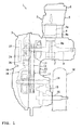
- Fig. 1 is a plan view of an engine unit
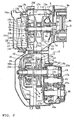
- Fig. 2 is a cross-sectional plan view of the continuously variable transmission
- Fig. 3 to Fig. 7 are side views of a case body, a case cover, a resin cover, an element, and an element cover, respectively.
- Fig. 8 to Fig. 10 are cross-sectional side views of an element mounting part
- Fig. 11 to Fig. 15 are perspective views illustrating the mounted state of the element, and a cooling air suction port and around it.
- the terms, "front”, “rear”, “right” and “left” are on the front, rear, right and left sides, with the engine unit mounted on a scooter-type motorcycle, viewed from the rider's seat thereof.
- the engine unit 1 includes an engine body 2 and a continuously variable transmission 3 which are integrated with each other, and is supported generally at the center of an under born type body frame for vertical swinging movement.
- the engine body 2 is disposed with its cylinder axis oriented generally horizontally, and generally includes a crankcase 7 made of an aluminum alloy, a cylinder block 4 and a cylinder head 5 stuck on a front wall of the crankcase 7 and secured thereto, and a head cover 6 removably attached to a front mating surface on the cylinder head 5.
- a piston 8a slidably inserted in a cylinder bore 4a formed in the cylinder block 4 is connected to a crankshaft 9 disposed in the crankcase 7 and extending in the vehicle width direction by a connecting rod 8b.
- the continuously variable transmission 3 has a transmission body housed in a transmission case 10 extending from the left side of the engine body 2 rearward on the left side of the vehicle.
- the transmission main body generally includes a driving pulley 11 attached to the left end of the crankshaft (driving shaft) 9 located on the engine body side in the transmission case 10, a driven pulley 12 attached to a driven shaft 14 located on the side of a rear wheel W, and a V-belt 13 wrapped around the driving pulley 11 and the driven pulley 12.
- Rotation of the driven shaft 14 is reduced in speed according to the gear ratio among gears 14b, 15a, 15b and 16a and transmitted to a rear wheel shaft 16 via an intermediate shaft 15 disposed in a gear chamber 20.
- the transmission case 10 has a case body 17 formed integrally with the crankcase 7 and extending to the rear wheel shaft 16, an aluminum alloy case cover 18 removably attached on the outside (left side) of the case body 17, and a resin cover 19 covering an outer surface of the case cover 18.
- the case body 17 has a rear inside wall 17a at a rear portion thereof.
- the rear inside wall 17a is bulged toward the rear wheel W and an inside cover 17b is attached to the inside of the bulged portion to form the gear chamber 20, which is oil tight.
- the crankshaft 9 has a left journal portion 9e journaled through a left wall 7a of the crankcase 7 via a bearing 21 b, and a pulley supporting portion 9a located on the left of the left journal portion 9e and protruded in the transmission case 10.
- the pulley supporting portion 9a has an end journaled in a bearing boss portion 18a via a bearing 21 a and a spacer 9c.
- the bearing boss portion 18a for supporting the end of the crankshaft 9 has an annular ring portion 18c for supporting the bearing 21 a and three leg portion 18d for joining the ring portion 18c integrally to the part of the case cover 18 constituting the bottom wall of a hereinafter-described blower casing 26.
- the driving pulley 11 is mounted on the pulley supporting portion 9a of the crankshaft 9.
- the driving pulley 11 has a movable half sheave of pulley 11 a mounted on a slide pipe 11c rotatable together with the pulley supporting portion 9a for sliding movement in the axial direction of the crankshaft and rotation together with the slide pipe 11c, and a fixed half sheave of pulley 11 b positioned in contact with the end of the slide pipe 11c and securely fixed to the pulley supporting portion 9a with a nut 9b.
- Designated as 9d is a spacer for filling the gap between the spacer 9c and the fixed half sheave of pulley 11 b in the axial direction. The spacers and are securely fixed to the pulley supporting portion 9a with the nut 9b.
- a weight 11e is interposed between a cam plate 11 d disposed on the back side of the movable half shave of pulley 11a and a stopper plate 11f secured to the pulley supporting portion 9a. With increase in the rotational speed of the crankshaft 9, the weight 11e is moved radially outward by centrifugal force to move the cam plate 11d and the movable half sheave of pulley 11a to the left. The effective diameter of the driving pulley 11 is therefore increased and the vehicle speed is increased.
- the driven pulley 12 is attached to a pulley supporting portion 14a of the driven shaft 14 protruded from the gear chamber 20 in the transmission case 10, and has a fixed half sheave of pulley 12a mounted on the pulley supporting portion 14a in such a manner as to be rotatable and immovable in the axial direction of the driven shaft, and a movable half sheave of pulley 12b mounted on a supporting pipe portion 12c of the fixed half sheave of pulley 12a for sliding movement in the axial direction of the driven shaft and rotation together with the supporting pipe 12c.
- the movable half sheave of pulley 12b is urged by an urging spring 12d in such a direction that the effective diameter of the driven pulley 12 increases.
- the driven shaft 14 has a gear chamber side portion which is journaled through the inner wall 17a and the inside cover 17b via bearings 23a and 23b, respectively, and an end which is journaled in a rear wall 18b of the case cover 18 via a bearing 23c.
- a centrifugal clutch 22 is interposed between an end of the supporting pipe 12c and an end of the driven shaft 14.
- the centrifugal clutch 22 has a weight arm 22a secured to the end of the supporting pipe 12c, a weight 22b attached to the arm 22a for oscillating movement in a radial direction of a circle about an axis parallel to the driven shaft 14, and a cup-shaped outer clutch 22c fixed to the driven shaft 14 side.
- the weight 22b With increase in the rotational speed of the driven pulley 12, the weight 22b is moved radially outward and brought into contact with the inner surface of the outer clutch 22c. The rotation of the driven pulley 12 is therefore transmitted to the driven shaft 14.
- a blower fan 24 for introducing air into the transmission case 10 from front, pressurizing the air, feeding the air to necessary parts, and discharging the air from rear, is mounted on the outside of the driving pulley 11 in the axial direction of the crankshaft.
- the blower fan 24 generally includes a multiplicity of blower vanes 25 and an air guide casing (blower casing) 26 surrounding the blower vanes.
- the blower fan 24 in this embodiment is rotated counterclockwise as viewed from the left side of the vehicle (the state shown in Fig. 3 ).
- the blower vanes 25 are arranged radially at equal angular intervals as viewed in the axial direction and formed integrally on the outer side of the fixed half shave of pulley 11b. As each of the blower vanes 25 is viewed in a direction perpendicular to the axial direction, the portion on the side of the center of the fixed half sheave of pulley 11b is removed and the portion on the side of the periphery of the fixed half sheave of pulley 11b is protruded outward in the axial direction.
- the bearing boss portion 18a is located in the portion where the blower vanes 25 are partially removed so that the blower fan 24 can be provided without increasing the dimension in the vehicle width direction.
- the air guide casing 26 has a plurality of sets (three sets in this embodiment) of boost passages 26a, 26b and 26c, each farther apart from the blowing vanes 25 than the one upstream thereof in the rotating direction of the blowing vanes 25.
- Discharge ports 26d to 26f are formed at the downstream ends of the boost passages 26a to 26c, respectively.
- the discharge ports 26d and 26e of the upper rear boost passage 26a and the lower rear boost passage 26b are placed generally in the middle between the driving pulley 11 and the driven pulley 12 and located in positions facing the portions of the V-belt 13 between the driving pulley 11 and the driven pulley 12 from outside. More specifically, the discharge ports 26d and 26e have generally rectangular shapes.
- the upper discharge port 26d is positioned with its long sides extending in a direction across the V-belt 13
- the lower discharge port 26e is positioned with its long sides generally parallel to the V-belt 13 and partially overlapped with the V-belt 13.
- the discharge port 26f of the front boost passage 26c is so shaped as to direct cooling air inward in the axial direction from a front peripheral portion of the driving pulley 11.
- the cooling air discharged from the discharge port 26f is supplied through a guide passage 17c formed at a front edge of the case body 17 to the back side of the movable half sheave of pulley 11a.
- the dot-dash lines show the V-belt 13 in idle state (the speed reduction ratio is maximum) and the V-belt at maximum speed (the speed reduction ratio is minimum).
- the V-belt 13 has portions 13a and 13b which hardly change positions whether it is in idle state or at maximum speed generally in the middle between the driving and driven pulleys 11 and 12.
- the discharge ports 26d and 26e are oriented toward the portions 13a and 13b of the V-belt 13 which hardly change positions whether at idle state or at maximum speed. Cooling air can therefore be constantly blown onto the V-belt 13 without greatly increasing the size of the discharge ports 26d and 26e, namely with the flow rate of the cooling air maintained at a high level.
- the boost passages 26a to 26c are constituted of outer peripheral portions 18e to 18g and a bottom wall 18h which are formed on the case cover 18, and a top wall 19f formed on the resin cover 19. More specifically, the outer peripheral portions 18e and 18g constituting the peripheral edges of the boost passages 26a to 26c are formed on the case cover 18 generally along tangents of the periphery of the driving pulley 11. Each peripheral portion is farther apart from the ends of the blower vanes 25 than the one upstream thereof in the rotating direction of the blower vanes 25. An opening 18i corresponding to the rotation locus of the blowing vanes 25 is formed and the residual portion constitutes the bottom wall 18h.
- the outer peripheral portions 18e and 18g constituting the boost passages on the case cover 18 are continuous with each other and form a closed loop as a whole.
- This closed loop is sealingly fitted in a seal groove 19c formed in the inner surface of the resin cover 19 and having the same closed loop shape.
- the resin cover 19 has an opening 19a having a diameter greater than that of the ring portion 18c of the bearing boss portion 18a and notches 19b to avoid interference with the leg portion 18d in the part inside the closed loop and opposed to the driving pulley 11.
- a slit-like space "a" formed between the opening 19a and the ring portion 18c constitutes an air passage.
- An element seal rib 19d in the form of a closed loop surrounding the leg portion 18d of the bearing boss portion 18c and a cover seal rib 19e in the form of a closed loop surrounding the element seal rib 19d are integrally formed on the outside surface of the resin cover 19.
- the element seal rib 19d is fitted in a seal groove 27a formed in an inner surface of an air cleaner element 27, and the cover seal rib 19e is fitted in a seal groove 28b of an air cleaner cover 28 covering the air cleaner element 27 from outside.
- the element 27 has a rectangular element main body 27b disposed inside the annular seal groove 27a. Air is introduced from a suction port 28a of the air cleaner cover 28 and passed through the element body 27b. The air is then introduced to the side of the blower fan 24 through the slit-like space "a", pressurized by rotation of the blower vanes 25, and passed through the boost passages 26a to 26c. Then, the air is discharged from the discharge ports 26d and 26e toward the intermediate portions 13a and 13b of the V-belt 13 which hardly change positions. The air is also discharged from the discharge port 26f and supplied through the guide passage 17c to the back side of the movable half sheave of pulley 11a. Then, the air flows in the transmission case 10 toward the driven pulley 12 and is discharged to the outside through discharge ports 17d and 17d formed through the part of the case body 17 below the driven pulley 12.
- the blower casing 26 surrounding the blower vanes 25 formed on the fixed half sheave of pulley 11b of the driving pulley 11 is provided on the side of the transmission case 10, and has boost passages 26a to 26c, each farther apart from the blower vanes 25 than the one upstream thereof in the rotating direction of the blower vanes, and discharge ports 26d to 26f formed at the downstream ends of the boost passages 26a and 26c, respectively.
- boost passages 26a to 26c each farther apart from the blower vanes 25 than the one upstream thereof in the rotating direction of the blower vanes, and discharge ports 26d to 26f formed at the downstream ends of the boost passages 26a and 26c, respectively.
- the discharge ports 26d and 26e of the upper rear and lower rear boost passages 26a and 26b are so shaped as to direct cooling air toward the V-belt 13.
- the V-belt 13 which is under severe thermal conditions, can be reliably cooled.
- the discharge ports 26d and 26e are so shaped as to direct cooling air toward the vicinity of the intermediate portions 13a and 13b of the V-belt, which are the points where the V-belt 13 in idle state and the V-belt 13 at maximum speed intersect with each other.
- cooling air can be supplied to the V-belt 13 over the whole operating region without enlarging the discharge ports 26d and 26e, namely with the flow rate of the cooling air maintained at a high level.
- the V-belt can be cooled reliably also in this regard.
- the cooling air discharged from the discharge port 26f of the boost passage 26c is supplied toward the back side of the movable half sheave of pulley 11 a of the driving pulley 11 located inside in the transmission case through the guide passage 17c.
- cooling air can be supplied to the part of the driving pulley 11 where the temperature becomes highest so that the temperature of the part can be prevented from becoming abnormally high.
- the blower casing 26 is formed on the side of the transmission case 10 by forming the outer peripheral portions 18e to 18g of the boost passages 26a and 26c on the case cover 18 and covering the outer peripheral portions 18e to 18g with the top wall 19f of the resin cover 19.
- the blower casing 26 can be constituted with a simple structure without using a special part.
- the bearing boss portion 18 for supporting the outside end of the crankshaft 9 is formed on the case cover 18, and the leg portion 18d of the bearing boss portion 18a are joined integrally to the bottom wall 18h of the blower casing 26.
- the blower casing 26 can be provided without increasing the number of parts and the outside end of the crankshaft 9 can be reliably supported.
- FIG. 16 shows a variation of the arrangement structure of the air cleaner element.
- An air cleaner element 37 in this variation has an annular element body 37a and a lid 37b closing an opening on one side of the element body 37a.
- An element cover 38 is disposed generally in contact with the lid 37b. Air is introduced into a space around the element body 37b and then flows in directions perpendicular to the axial direction into the element body 37. The air is then sucked into the blowing fan 24 through the slit-like space "a".
- a cooling structure for a V-belt type continuously variable transmission which can enhance blowing efficiency and increase the amount of cooling air and which can positively supply cooling air to parts which need to be cooled.
- a cooling structure for a V-belt type continuously variable transmission 3 having a driving pulley 11 mounted on a driving shaft 9 disposed on the engine side in a transmission case 10, a driven pulley 12 mounted on a driven shaft 14 disposed on the rear wheel side in the transmission case, and a V-belt 13 wrapped around the driving pulley and the driven pulley, comprising: a blower fan 24 provided on an outside surface of a half sheave of the driving pulley 11 located on the outer side in the transmission case 10; and a blower casing 26 provided on the side of the transmission case 10 and surrounding the blower fan 24, wherein the blower casing 26 has boost passages 26a to 26c, each farther apart from the blower fan 24 than the one upstream thereof in the rotating direction of the blower vane, and discharge ports 26d to 26f
- a cooling structure for a V-belt type continuously variable transmission 3 having a driving pulley 11 mounted on a driving shaft 9 disposed on the engine side in a transmission case 10, a driven pulley 12 mounted on a driven shaft 14 disposed on the rear wheel side in said transmission case 10, and a V-belt 13 wrapped around said driving pulley 11 and said driven pulley 12, comprising: a blower fan 24 provided on an outside surface of a half sheave of said driving pulley 11 located on the outer side in said transmission case 10; and a blower casing 26 provided on the side of said transmission case 10 and surrounding said blower fan 24; wherein said blower casing 26 has boost passages 26a-26e, each farther apart from said blower fan 24 than the one upstream thereof in the rotating direction of said blower fan 24, and discharge ports 26d-26f formed at the downstream ends of said boost passages 26a-26e.
- a blower casing surrounding a blower fan is provided on the side of the transmission case, and has boost passages, each farther apart from the blower fan than the one upstream thereof in the rotating direction of the blower fan, and discharge ports formed at the downstream ends of the boost passages.
- said transmission case 10 comprises a case body 17 formed integrally with a crankcase 7 of an engine, a metal case cover 18 removably attached to said case body 17, and a resin cover 19 for covering the outside surface of said case cover 18, and wherein said blower casing 26 is formed by covering outer peripheral portions 18e-18g of said boost passages 26a-26e formed on said case cover 18 with said resin cover 19.
- the transmission case comprises a case body formed integrally with a crankcase of an engine, a metal case cover removably attached to the case body, and a resin cover for covering the outside surface of the case cover, and the blower casing is formed by covering outer peripheral portions of the boost passages formed on the case cover with the resin cover.
- the blower casing can be constituted with a simple structure without using a special part.
- a bearing boss portion 18 for supporting a bearing 21 a for supporting the outside end of said driving shaft 9 is formed integrally with said case cover 18, said bearing boss portion 18 having an annular ring portion 18c for supporting said bearing 21 a and a leg portion 18d for joining said ring portion 18c integrally to a bottom surface of said blower casing 26.
- a bearing boss portion for supporting a bearing for supporting the outside end of the driving shaft is formed integrally with the case cover and has and a leg portion joined integrally to a bottom surface of the blower casing.
- said discharge ports 26d-26f are so shaped as to direct pressurized cooling air toward said V-belt 13.
- the discharge ports are so shaped as to direct pressurized cooling air toward the V-belt.
- the V-belt which is under severe thermal conditions, can be reliably cooled.
- said discharge ports 26d-26f are so shaped as to direct cooling air toward the vicinity of the points 13a,13b where said V-belt 13 in idle state and said V-belt 13 at maximum speed intersect with each other.
- the discharge ports are so shaped as to direct cooling air toward the vicinity of the points where the V-belt in idle state and the V-belt at maximum speed intersect with each other.
- cooling air can be supplied to the V-belt over the whole operating region without enlarging the discharge, namely with the flow rate of the cooling air maintained at a high level.
- the V-belt can be cooled reliably also in this regard.
- One embodiment is configured to guide cooling air discharged from a discharge port 26f toward a half sheave 11a of said driving pulley 11 located on the inner side in said transmission case 10.
- the cooling structure is configured to guide cooling air discharged from the discharge ports toward a half sheave of the driving pulley located on the inner side in the transmission case.
- cooling air can be supplied to the part of the driving pulley where the temperature becomes highest so that the temperature of the part can be prevented from becoming abnormally high.
- V-belt type continuously variable transmission having a driving pulley 11 mounted on a driving shaft 9 and a driven pulley 12 mounted on a driven shaft 14 disposed in a transmission case 10.
- a V-belt 13 is wrapped around said driving pulley 11 and said driven pulley 12.
- a cooling means comprises a blower fan 24 provided in said transmission case 10, and a blower casing 26 is surrounding said blower fan 24.
- Said blower casing 26 has boost passages 26a-26e, each farther apart from said blower fan 24 than the one upstream thereof in the rotating direction of said blower fan 24.
- Discharge ports 26d-26f are formed at the downstream ends of said boost passages 26a-26e.
- Said V-belt type continuously variable transmission further comprises a first cover 18 removably attached to a case body 17 of said transmission case 10, and a second cover 19 for covering the outside surface of said first cover 18.
- Said blower casing 26 is formed by covering outer peripheral portions 18e-18g of said boost passages 26a-26e formed on said first cover 18 with said second cover 19.
- Said case body 17 is formed integrally with a crankcase 7 of an engine.
- Said first cover is a metal case cover 18, and said second cover is a resin cover 19.
- the V-belt type continuously variable transmission comprises a bearing boss portion 18 for supporting a bearing 21a for supporting the outside end of said driving shaft 9).
- Said bearing boss portion 18 is formed integrally with said first cover 18.
- Said bearing boss portion 18 has an annular ring portion 18c for supporting said bearing 21a and a leg portion 18d for joining said ring portion 18c integrally to a bottom surface of said blower casing 26.
- Said driving pulley 11 mounted on a driving shaft 9 is disposed on an engine side in the transmission case 10.
- Said driven pulley 12 mounted on the driven shaft 14 is disposed on a rear wheel side in said transmission case 10.
- Said blower fan 24 is provided on an outside surface of a half sheave 11b of said driving pulley 11 located on an outer side in said transmission case 10.
- the blower casing 26 is provided on the outer side of said transmission case 10.
- Said discharge ports 26d-26f are so shaped as to direct pressurized cooling air toward said V-belt 13.
- Said discharge ports 26d-26f are so shaped as to direct cooling air toward the vicinity of the points 13a,13b where said V-belt 13 in idle state and said V-belt 13 at maximum speed intersect with each other.
- the V-belt type continuously variable transmission is configured to guide cooling air discharged from said discharge ports 26d-26f toward a half sheave 11a of said driving pulley 11 located on the inner side in said transmission case 10.
- the embodiments mentioned above are further teaching an engine unit, especially for a scooter type vehicle, comprising an internal combustion engine and a V-belt type continuously variable transmission according to the embodiments.
Description
- The present invention relates to a V-belt type continuously variable transmission. Such a V-belt type continuously variable transmission can be taken from the prior art document
JP 55-139554 A - In one conventional cooling structure for a V-belt type continuously variable transmission suitable for use in a motorcycle such as a scooter, blower vanes are provided on a pulley constituting the V-belt type continuously variable transmission so that cooling air can be introduced into a transmission case by rotation of the blower vanes,(see for example
JP-A-Hei 3-130523 - In the above conventional cooling structure, cooling air is introduced into the transmission case by rotating the blower vanes in the transmission case. However, the transmission case itself is not constituted in view of improving blowing efficiency. Thus, sufficient amount of cooling air cannot be necessarily secured.
- Also in the conventional structure, cooling air is introduced into the transmission case from the driving pulley side and discharged from the driven pulley side to simply ventilate the inside of the transmission case. Thus; cooling air is not positively supplied to parts which may develop a problem from the standpoint of heat resistance and thus need to be cooled in particular, such as a V-belt.
- It is an objective of the present invention to provide a V-belt type continuously variable transmission as mentioned above having a high cooling efficiency.
- According to the present invention, said objective is solved by a V-belt type continuously variable transmission having the features of
independent claim 1. - Accordingly, there is provided a cooling structure for a V-belt type continuously variable transmission which can enhance blowing efficiency and increase the amount of cooling air and which can positively supply cooling air to parts which need to be cooled.
- Preferably, said case body is formed integrally with a crankcase of an engine associated to said transmission.
- According to a preferred embodiment, said first cover is a metal case cover, and said second cover is a resin cover.
- According to a preferred embodiment, a bearing boss portion for supporting a bearing for supporting the outside end of said driving shaft is formed integrally with said first cover, said bearing boss portion having an annular ring portion for supporting said bearing and a leg portion for joining said ring portion integrally to a bottom surface of said blower casing.
- According to a preferred embodiment, said driving pulley mounted on a driving shaft is disposed on an engine side in the transmission case being adapted to be connected to an engine of a vehicle, said driven pulley mounted on the driven shaft is disposed on a rear wheel side in said transmission case being adapted to be connected to a rear wheel of a vehicle, and said blower fan provided on an outside surface of a half sheave of said driving pulley located on an outer side in said transmission case; and the blower casing is provided on the outer side of said transmission case.
- A preferred embodiment is configured to guide cooling air discharged from a discharge port toward a half sheave of said driving pulley located on the inner side in said transmission case.
- In consideration of the object there is also proved an engine unit, especially for a scooter type vehicle, comprising an internal combustion engine and a V-belt type continuously variable transmission mentioned above.
- Hereinafter, the present invention is illustrated and explained by means of preferred embodiments in conjunction with the accompanying drawings. In the drawings wherein:
- Fig. 1
- is a plan view of an engine unit provided with a cooling structure for a V-belt type continuously variable transmission according to an embodiment,
- Fig. 2
- is a cross-sectional plan view of a transmission in the above embodiment,
- Fig. 3
- is a side view illustrating a case body in the above embodiment,
- Fig. 4
- is a side view illustrating a case cover in the above embodiment,
- Fig. 5
- is a side view illustrating a resin cover in the above embodiment,
- Fig. 6
- is a side view illustrating an element in the above embodiment,
- Fig. 7
- is a side view illustrating the case cover in the above embodiment,
- Fig. 8
- is a cross-sectional side view (cross-sectional view taken along the line VIII-VIII in
Fig. 5 ) illustrating the installation state of the element in the above embodiment, - Fig. 9
- is a cross-sectional side view (cross-sectional view taken along the line IX-IX in
Fig. 5 ) illustrating the installation state of the element in the above embodiment, - Fig. 10
- is a cross-sectional side view (cross-sectional view taken along the line X-X in
Fig. 5 ) illustrating a lower rear discharge port and around it, - Fig. 11
- is a perspective view illustrating the installation state of the element in the above embodiment,
- Fig. 12
- is a side view illustrating the state where the element is removed in the above embodiment,
- Fig. 13
- is a perspective view illustrating the state where the element is removed in the above embodiment,
- Fig. 14
- is a side view illustrating the state where the resin cover is removed in the above embodiment,
- Fig. 15
- is perspective view illustrating the state where the resin cover is removed in the above embodiment, and
- Fig. 16
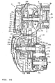
- is a cross-sectional side view illustrating a variation of the element in the above embodiment.
-
Fig. 1 to Fig. 15 are views for explaining a cooling structure for a V-belt type continuously variable transmission according to an embodiment.Fig. 1 is a plan view of an engine unit,Fig. 2 is a cross-sectional plan view of the continuously variable transmission,Fig. 3 to Fig. 7 are side views of a case body, a case cover, a resin cover, an element, and an element cover, respectively.Fig. 8 to Fig. 10 are cross-sectional side views of an element mounting part,Fig. 11 to Fig. 15 are perspective views illustrating the mounted state of the element, and a cooling air suction port and around it. In this embodiment, the terms, "front", "rear", "right" and "left" are on the front, rear, right and left sides, with the engine unit mounted on a scooter-type motorcycle, viewed from the rider's seat thereof. - In the drawings, designated as 1 is a unit swing type engine unit for a scooter-type motorcycle. The
engine unit 1 includes anengine body 2 and a continuouslyvariable transmission 3 which are integrated with each other, and is supported generally at the center of an under born type body frame for vertical swinging movement. - The
engine body 2 is disposed with its cylinder axis oriented generally horizontally, and generally includes acrankcase 7 made of an aluminum alloy, acylinder block 4 and a cylinder head 5 stuck on a front wall of thecrankcase 7 and secured thereto, and a head cover 6 removably attached to a front mating surface on the cylinder head 5. Apiston 8a slidably inserted in acylinder bore 4a formed in thecylinder block 4 is connected to acrankshaft 9 disposed in thecrankcase 7 and extending in the vehicle width direction by a connectingrod 8b. - The continuously
variable transmission 3 has a transmission body housed in atransmission case 10 extending from the left side of theengine body 2 rearward on the left side of the vehicle. The transmission main body generally includes adriving pulley 11 attached to the left end of the crankshaft (driving shaft) 9 located on the engine body side in thetransmission case 10, a drivenpulley 12 attached to a drivenshaft 14 located on the side of a rear wheel W, and a V-belt 13 wrapped around thedriving pulley 11 and the drivenpulley 12. Rotation of the drivenshaft 14 is reduced in speed according to the gear ratio amonggears rear wheel shaft 16 via anintermediate shaft 15 disposed in agear chamber 20. - The
transmission case 10 has acase body 17 formed integrally with thecrankcase 7 and extending to therear wheel shaft 16, an aluminumalloy case cover 18 removably attached on the outside (left side) of thecase body 17, and aresin cover 19 covering an outer surface of thecase cover 18. Thecase body 17 has a rear insidewall 17a at a rear portion thereof. The rear insidewall 17a is bulged toward the rear wheel W and aninside cover 17b is attached to the inside of the bulged portion to form thegear chamber 20, which is oil tight. - The
crankshaft 9 has aleft journal portion 9e journaled through aleft wall 7a of thecrankcase 7 via a bearing 21 b, and apulley supporting portion 9a located on the left of theleft journal portion 9e and protruded in thetransmission case 10. Thepulley supporting portion 9a has an end journaled in abearing boss portion 18a via a bearing 21 a and aspacer 9c. - The bearing
boss portion 18a for supporting the end of thecrankshaft 9 has anannular ring portion 18c for supporting the bearing 21 a and threeleg portion 18d for joining thering portion 18c integrally to the part of the case cover 18 constituting the bottom wall of a hereinafter-describedblower casing 26. - The driving
pulley 11 is mounted on thepulley supporting portion 9a of thecrankshaft 9. The drivingpulley 11 has a movable half sheave of pulley 11 a mounted on aslide pipe 11c rotatable together with thepulley supporting portion 9a for sliding movement in the axial direction of the crankshaft and rotation together with theslide pipe 11c, and a fixed half sheave ofpulley 11 b positioned in contact with the end of theslide pipe 11c and securely fixed to thepulley supporting portion 9a with anut 9b. Designated as 9d is a spacer for filling the gap between the spacer 9c and the fixed half sheave ofpulley 11 b in the axial direction. The spacers and are securely fixed to thepulley supporting portion 9a with thenut 9b. - A weight 11e is interposed between a
cam plate 11 d disposed on the back side of the movable half shave of pulley 11a and astopper plate 11f secured to thepulley supporting portion 9a. With increase in the rotational speed of thecrankshaft 9, the weight 11e is moved radially outward by centrifugal force to move thecam plate 11d and the movable half sheave of pulley 11a to the left. The effective diameter of the drivingpulley 11 is therefore increased and the vehicle speed is increased. - The driven
pulley 12 is attached to apulley supporting portion 14a of the drivenshaft 14 protruded from thegear chamber 20 in thetransmission case 10, and has a fixed half sheave ofpulley 12a mounted on thepulley supporting portion 14a in such a manner as to be rotatable and immovable in the axial direction of the driven shaft, and a movable half sheave ofpulley 12b mounted on a supportingpipe portion 12c of the fixed half sheave ofpulley 12a for sliding movement in the axial direction of the driven shaft and rotation together with the supportingpipe 12c. The movable half sheave ofpulley 12b is urged by an urgingspring 12d in such a direction that the effective diameter of the drivenpulley 12 increases. The drivenshaft 14 has a gear chamber side portion which is journaled through theinner wall 17a and theinside cover 17b viabearings rear wall 18b of the case cover 18 via abearing 23c. - A
centrifugal clutch 22 is interposed between an end of the supportingpipe 12c and an end of the drivenshaft 14. The centrifugal clutch 22 has aweight arm 22a secured to the end of the supportingpipe 12c, aweight 22b attached to thearm 22a for oscillating movement in a radial direction of a circle about an axis parallel to the drivenshaft 14, and a cup-shaped outer clutch 22c fixed to the drivenshaft 14 side. - With increase in the rotational speed of the driven
pulley 12, theweight 22b is moved radially outward and brought into contact with the inner surface of the outer clutch 22c. The rotation of the drivenpulley 12 is therefore transmitted to the drivenshaft 14. - On the
crankshaft 9, ablower fan 24, for introducing air into thetransmission case 10 from front, pressurizing the air, feeding the air to necessary parts, and discharging the air from rear, is mounted on the outside of the drivingpulley 11 in the axial direction of the crankshaft. Theblower fan 24 generally includes a multiplicity ofblower vanes 25 and an air guide casing (blower casing) 26 surrounding the blower vanes. Theblower fan 24 in this embodiment is rotated counterclockwise as viewed from the left side of the vehicle (the state shown inFig. 3 ). - The blower vanes 25 are arranged radially at equal angular intervals as viewed in the axial direction and formed integrally on the outer side of the fixed half shave of
pulley 11b. As each of theblower vanes 25 is viewed in a direction perpendicular to the axial direction, the portion on the side of the center of the fixed half sheave ofpulley 11b is removed and the portion on the side of the periphery of the fixed half sheave ofpulley 11b is protruded outward in the axial direction. The bearingboss portion 18a is located in the portion where theblower vanes 25 are partially removed so that theblower fan 24 can be provided without increasing the dimension in the vehicle width direction. - As shown in
Fig. 4 andFig. 5 , theair guide casing 26 has a plurality of sets (three sets in this embodiment) ofboost passages vanes 25 than the one upstream thereof in the rotating direction of the blowingvanes 25.Discharge ports 26d to 26f are formed at the downstream ends of theboost passages 26a to 26c, respectively. - As shown in
Fig. 3 , thedischarge ports rear boost passage 26a and the lowerrear boost passage 26b are placed generally in the middle between the drivingpulley 11 and the drivenpulley 12 and located in positions facing the portions of the V-belt 13 between the drivingpulley 11 and the drivenpulley 12 from outside. More specifically, thedischarge ports upper discharge port 26d is positioned with its long sides extending in a direction across the V-belt 13, and thelower discharge port 26e is positioned with its long sides generally parallel to the V-belt 13 and partially overlapped with the V-belt 13. - The
discharge port 26f of thefront boost passage 26c is so shaped as to direct cooling air inward in the axial direction from a front peripheral portion of the drivingpulley 11. The cooling air discharged from thedischarge port 26f is supplied through aguide passage 17c formed at a front edge of thecase body 17 to the back side of the movable half sheave of pulley 11a. - In
Fig. 3 , the dot-dash lines show the V-belt 13 in idle state (the speed reduction ratio is maximum) and the V-belt at maximum speed (the speed reduction ratio is minimum). As is clear from the drawing, the V-belt 13 hasportions pulleys discharge ports portions belt 13 which hardly change positions whether at idle state or at maximum speed. Cooling air can therefore be constantly blown onto the V-belt 13 without greatly increasing the size of thedischarge ports - The
boost passages 26a to 26c are constituted of outerperipheral portions 18e to 18g and abottom wall 18h which are formed on thecase cover 18, and atop wall 19f formed on theresin cover 19. More specifically, the outerperipheral portions boost passages 26a to 26c are formed on the case cover 18 generally along tangents of the periphery of the drivingpulley 11. Each peripheral portion is farther apart from the ends of theblower vanes 25 than the one upstream thereof in the rotating direction of theblower vanes 25. Anopening 18i corresponding to the rotation locus of the blowingvanes 25 is formed and the residual portion constitutes thebottom wall 18h. The outerperipheral portions seal groove 19c formed in the inner surface of theresin cover 19 and having the same closed loop shape. - The
resin cover 19 has anopening 19a having a diameter greater than that of thering portion 18c of the bearingboss portion 18a andnotches 19b to avoid interference with theleg portion 18d in the part inside the closed loop and opposed to the drivingpulley 11. A slit-like space "a" formed between theopening 19a and thering portion 18c constitutes an air passage. - An
element seal rib 19d in the form of a closed loop surrounding theleg portion 18d of the bearingboss portion 18c and acover seal rib 19e in the form of a closed loop surrounding theelement seal rib 19d are integrally formed on the outside surface of theresin cover 19. - The
element seal rib 19d is fitted in aseal groove 27a formed in an inner surface of an aircleaner element 27, and thecover seal rib 19e is fitted in aseal groove 28b of an aircleaner cover 28 covering theair cleaner element 27 from outside. - The
element 27 has a rectangular elementmain body 27b disposed inside theannular seal groove 27a. Air is introduced from asuction port 28a of the aircleaner cover 28 and passed through theelement body 27b. The air is then introduced to the side of theblower fan 24 through the slit-like space "a", pressurized by rotation of theblower vanes 25, and passed through theboost passages 26a to 26c. Then, the air is discharged from thedischarge ports intermediate portions belt 13 which hardly change positions. The air is also discharged from thedischarge port 26f and supplied through theguide passage 17c to the back side of the movable half sheave of pulley 11a. Then, the air flows in thetransmission case 10 toward the drivenpulley 12 and is discharged to the outside throughdischarge ports case body 17 below the drivenpulley 12. - As has been described previously, the
blower casing 26 surrounding theblower vanes 25 formed on the fixed half sheave ofpulley 11b of the drivingpulley 11 is provided on the side of thetransmission case 10, and hasboost passages 26a to 26c, each farther apart from theblower vanes 25 than the one upstream thereof in the rotating direction of the blower vanes, anddischarge ports 26d to 26f formed at the downstream ends of theboost passages blower vanes 25 while being passed through theboost passages 26a to 26c and discharged through thedischarge ports 26d to 26f. Therefore, blowing efficiency is enhanced and the amount of cooling air can be considerably increased. - The
discharge ports rear boost passages belt 13. Thus, the V-belt 13, which is under severe thermal conditions, can be reliably cooled. - In addition, the
discharge ports intermediate portions belt 13 in idle state and the V-belt 13 at maximum speed intersect with each other. Thus, cooling air can be supplied to the V-belt 13 over the whole operating region without enlarging thedischarge ports - The cooling air discharged from the
discharge port 26f of theboost passage 26c is supplied toward the back side of the movable half sheave of pulley 11 a of the drivingpulley 11 located inside in the transmission case through theguide passage 17c. Thus, cooling air can be supplied to the part of the drivingpulley 11 where the temperature becomes highest so that the temperature of the part can be prevented from becoming abnormally high. - The
blower casing 26 is formed on the side of thetransmission case 10 by forming the outerperipheral portions 18e to 18g of theboost passages case cover 18 and covering the outerperipheral portions 18e to 18g with thetop wall 19f of theresin cover 19. Thus, theblower casing 26 can be constituted with a simple structure without using a special part. - The bearing
boss portion 18 for supporting the outside end of thecrankshaft 9 is formed on thecase cover 18, and theleg portion 18d of the bearingboss portion 18a are joined integrally to thebottom wall 18h of theblower casing 26. Thus, theblower casing 26 can be provided without increasing the number of parts and the outside end of thecrankshaft 9 can be reliably supported. -
Fig. 16 shows a variation of the arrangement structure of the air cleaner element. In the drawing, the same reference numerals as inFig. 2 indicate the same or corresponding parts. An aircleaner element 37 in this variation has anannular element body 37a and alid 37b closing an opening on one side of theelement body 37a. An element cover 38 is disposed generally in contact with thelid 37b. Air is introduced into a space around theelement body 37b and then flows in directions perpendicular to the axial direction into theelement body 37. The air is then sucked into the blowingfan 24 through the slit-like space "a". - In this variation, there is need to provide only a small gap between the
element 37 and theelement cover 38. Thus, increase in dimension in the vehicle width direction can be prevented. - A cooling structure for a V-belt type continuously variable transmission is provided which can enhance blowing efficiency and increase the amount of cooling air and which can positively supply cooling air to parts which need to be cooled. In particular a cooling structure for a V-belt type continuously
variable transmission 3 is provided having a drivingpulley 11 mounted on a drivingshaft 9 disposed on the engine side in atransmission case 10, a drivenpulley 12 mounted on a drivenshaft 14 disposed on the rear wheel side in the transmission case, and a V-belt 13 wrapped around the driving pulley and the driven pulley, comprising: ablower fan 24 provided on an outside surface of a half sheave of the drivingpulley 11 located on the outer side in thetransmission case 10; and ablower casing 26 provided on the side of thetransmission case 10 and surrounding theblower fan 24, wherein theblower casing 26 hasboost passages 26a to 26c, each farther apart from theblower fan 24 than the one upstream thereof in the rotating direction of the blower vane, anddischarge ports 26d to 26f formed at the downstream ends of theboost passages 26a to 26c. - Accordingly it is provided a cooling structure for a V-belt type continuously
variable transmission 3 having a drivingpulley 11 mounted on a drivingshaft 9 disposed on the engine side in atransmission case 10, a drivenpulley 12 mounted on a drivenshaft 14 disposed on the rear wheel side in saidtransmission case 10, and a V-belt 13 wrapped around said drivingpulley 11 and said drivenpulley 12, comprising: ablower fan 24 provided on an outside surface of a half sheave of said drivingpulley 11 located on the outer side in saidtransmission case 10; and ablower casing 26 provided on the side of saidtransmission case 10 and surrounding saidblower fan 24; wherein saidblower casing 26 hasboost passages 26a-26e, each farther apart from saidblower fan 24 than the one upstream thereof in the rotating direction of saidblower fan 24, anddischarge ports 26d-26f formed at the downstream ends of saidboost passages 26a-26e. - Accordingly, a blower casing surrounding a blower fan is provided on the side of the transmission case, and has boost passages, each farther apart from the blower fan than the one upstream thereof in the rotating direction of the blower fan, and discharge ports formed at the downstream ends of the boost passages. Thus, since cooling air is discharged from the discharge port while being pressurized by rotation of the blower fan, blowing efficiency can be improved. The amount of cooling air can be therefore considerably increased as compared with a cooling structure which simply stirs air in a transmission case and ventilate it. Also, by determining the positions of the discharge ports properly, cooling air can be supplied to parts which need to be cooled in particular with high efficiency.
- In one embodiment, said
transmission case 10 comprises acase body 17 formed integrally with acrankcase 7 of an engine, a metal case cover 18 removably attached to saidcase body 17, and aresin cover 19 for covering the outside surface of saidcase cover 18, and wherein saidblower casing 26 is formed by covering outerperipheral portions 18e-18g of saidboost passages 26a-26e formed on said case cover 18 with saidresin cover 19. - Accordingly, the transmission case comprises a case body formed integrally with a crankcase of an engine, a metal case cover removably attached to the case body, and a resin cover for covering the outside surface of the case cover, and the blower casing is formed by covering outer peripheral portions of the boost passages formed on the case cover with the resin cover. Thus, the blower casing can be constituted with a simple structure without using a special part.
- In one embodiment, a bearing
boss portion 18 for supporting a bearing 21 a for supporting the outside end of said drivingshaft 9 is formed integrally with saidcase cover 18, saidbearing boss portion 18 having anannular ring portion 18c for supporting said bearing 21 a and aleg portion 18d for joining saidring portion 18c integrally to a bottom surface of saidblower casing 26. - Accordingly, a bearing boss portion for supporting a bearing for supporting the outside end of the driving shaft is formed integrally with the case cover and has and a leg portion joined integrally to a bottom surface of the blower casing. Thus, the blower casing can be provided without increasing the number of parts and the outside end of the driving shaft can be reliably supported.
- According to the invention, said
discharge ports 26d-26f are so shaped as to direct pressurized cooling air toward said V-belt 13. - Accordingly, the discharge ports are so shaped as to direct pressurized cooling air toward the V-belt. Thus, the V-belt, which is under severe thermal conditions, can be reliably cooled.
- Further according to the invention, said
discharge ports 26d-26f are so shaped as to direct cooling air toward the vicinity of thepoints belt 13 in idle state and said V-belt 13 at maximum speed intersect with each other. - Accordingly, the discharge ports are so shaped as to direct cooling air toward the vicinity of the points where the V-belt in idle state and the V-belt at maximum speed intersect with each other. Thus, cooling air can be supplied to the V-belt over the whole operating region without enlarging the discharge, namely with the flow rate of the cooling air maintained at a high level. The V-belt can be cooled reliably also in this regard.
- One embodiment is configured to guide cooling air discharged from a
discharge port 26f toward a half sheave 11a of said drivingpulley 11 located on the inner side in saidtransmission case 10. - Accordingly, the cooling structure is configured to guide cooling air discharged from the discharge ports toward a half sheave of the driving pulley located on the inner side in the transmission case. Thus, cooling air can be supplied to the part of the driving pulley where the temperature becomes highest so that the temperature of the part can be prevented from becoming abnormally high.
- The embodiments mentioned above are teaching a V-belt type continuously variable transmission having a driving
pulley 11 mounted on a drivingshaft 9 and a drivenpulley 12 mounted on a drivenshaft 14 disposed in atransmission case 10. A V-belt 13 is wrapped around said drivingpulley 11 and said drivenpulley 12. A cooling means comprises ablower fan 24 provided in saidtransmission case 10, and ablower casing 26 is surrounding saidblower fan 24. Saidblower casing 26 hasboost passages 26a-26e, each farther apart from saidblower fan 24 than the one upstream thereof in the rotating direction of saidblower fan 24.Discharge ports 26d-26f are formed at the downstream ends of saidboost passages 26a-26e. - Said V-belt type continuously variable transmission further comprises a
first cover 18 removably attached to acase body 17 of saidtransmission case 10, and asecond cover 19 for covering the outside surface of saidfirst cover 18. Saidblower casing 26 is formed by covering outerperipheral portions 18e-18g of saidboost passages 26a-26e formed on saidfirst cover 18 with saidsecond cover 19. Saidcase body 17 is formed integrally with acrankcase 7 of an engine. Said first cover is ametal case cover 18, and said second cover is aresin cover 19. - The V-belt type continuously variable transmission according to the embodiment comprises a
bearing boss portion 18 for supporting abearing 21a for supporting the outside end of said driving shaft 9). Said bearingboss portion 18 is formed integrally with saidfirst cover 18. Said bearingboss portion 18 has anannular ring portion 18c for supporting saidbearing 21a and aleg portion 18d for joining saidring portion 18c integrally to a bottom surface of saidblower casing 26. - Said driving
pulley 11 mounted on a drivingshaft 9 is disposed on an engine side in thetransmission case 10. Said drivenpulley 12 mounted on the drivenshaft 14 is disposed on a rear wheel side in saidtransmission case 10. Saidblower fan 24 is provided on an outside surface of ahalf sheave 11b of said drivingpulley 11 located on an outer side in saidtransmission case 10. Theblower casing 26 is provided on the outer side of saidtransmission case 10. - Said
discharge ports 26d-26f are so shaped as to direct pressurized cooling air toward said V-belt 13. Saiddischarge ports 26d-26f are so shaped as to direct cooling air toward the vicinity of thepoints belt 13 in idle state and said V-belt 13 at maximum speed intersect with each other. The V-belt type continuously variable transmission is configured to guide cooling air discharged from saiddischarge ports 26d-26f toward a half sheave 11a of said drivingpulley 11 located on the inner side in saidtransmission case 10. - The embodiments mentioned above are further teaching an engine unit, especially for a scooter type vehicle, comprising an internal combustion engine and a V-belt type continuously variable transmission according to the embodiments.
Claims (7)
- A V-belt type continuously variable transmission having a driving pulley (11) mounted on a driving shaft (9) and a driven pulley (12) mounted on a driven shaft (14) disposed in a transmission case (10), and a V-belt (13) wrapped around said driving pulley (11) and said driven pulley (12),
a cooling means comprising a blower fan (24) provided in said transmission case (10), and a blower casing (26) surrounding said blower fan (24), wherein
a case cover (18) is removably attached to a case body (17) of said transmission case (10) forming boost passages (26a-26c) by outer peripheral portions (18e-18g) and a bottom wall (18h) thereof in conjunction with a second cover (19) covering the outside surface of the case cover (18), wherein said blower casing (26) is formed by covering said outer peripheral portions (18e-18g) of the case cover (18) with said second cover (19) and discharge ports (26d-26f) are formed at the downstream ends of said boost passages (26a-26c) and discharge ports are shaped to direct cooling air toward the vicinity of the points where said V-belt (13) in idle state and at maximum speed intersect with each other. - A V-beit type continuously variable transmission according to claim 1, characterized in that said case body (17) is formed integrally with a crankcase (7) of an engine.
- A V-belt type continuously variable transmission according to claim 1 or 2, characterized in that said first cover is a metal case cover (18), and said second cover is a resin cover (19).
- A V-belt type continuously variable transmission according to at least one of the claims 2 to 3, characterized in that a bearing boss portion (18) for supporting a bearing (21a) for supporting the outside end of said driving shaft (9) is formed integrally with said first cover (18), said bearing boss portion (18) having an annular ring portion (18c) for supporting said bearing (21 a) and a leg portion (18d) for joining said ring portion (18c) integrally to a bottom surface of said blower casing (26).
- A V-belt type continuously variable transmission according to at least one of the claims 1 to 4, characterized in that said driving pulley (11) mounted on a driving shaft (9) is disposed on an engine side in the transmission case (10), said driven pulley (12) mounted on the driven shaft (14) is disposed on a rear wheel side in said transmission case (10), and said blower fan (24) provided on an outside surface of a half sheave (11b) of said driving pulley (11) located on an outer side in said transmission case (10); and the blower casing (26) is provided on the outer side of said transmission case (10).
- A V-belt type continuously variable transmission according to at least one of the claims 1 to 5, configured to guide cooling air discharged from a discharge port (26f) toward a half sheave (11a) of said driving pulley (11) located on the inner side in said transmission case (10).
- An engine unit, especially for a scooter type vehicle, comprising an internal combustion engine and a V-belt type continuously variable transmission according to at least one of the claims 1 to 6.
Applications Claiming Priority (2)
| Application Number | Priority Date | Filing Date | Title |
|---|---|---|---|
| JP2002376369A JP4359040B2 (en) | 2002-12-26 | 2002-12-26 | Cooling structure for V-belt type continuously variable transmission |
| JP2002376369 | 2002-12-26 |
Publications (3)
| Publication Number | Publication Date |
|---|---|
| EP1433645A2 EP1433645A2 (en) | 2004-06-30 |
| EP1433645A3 EP1433645A3 (en) | 2006-06-07 |
| EP1433645B1 true EP1433645B1 (en) | 2010-02-24 |
Family
ID=32463566
Family Applications (1)
| Application Number | Title | Priority Date | Filing Date |
|---|---|---|---|
| EP03029243A Expired - Lifetime EP1433645B1 (en) | 2002-12-26 | 2003-12-18 | V-belt type continuously variable transmission |
Country Status (4)
| Country | Link |
|---|---|
| EP (1) | EP1433645B1 (en) |
| JP (1) | JP4359040B2 (en) |
| DE (1) | DE60331405D1 (en) |
| ES (1) | ES2340474T3 (en) |
Cited By (1)
| Publication number | Priority date | Publication date | Assignee | Title |
|---|---|---|---|---|
| CN109070733A (en) * | 2016-04-28 | 2018-12-21 | 庞巴迪动力产品公司 | Cooling system for turbocharger and adjacent components |
Families Citing this family (9)
| Publication number | Priority date | Publication date | Assignee | Title |
|---|---|---|---|---|
| DE602007003411D1 (en) * | 2006-07-19 | 2010-01-07 | Honda Motor Co Ltd | motorcycle |
| EP2123942B1 (en) * | 2006-11-29 | 2011-04-20 | Yamaha Hatsudoki Kabushiki Kaisha | Motorcycle |
| CN101737485B (en) * | 2008-11-11 | 2013-01-23 | 光阳工业股份有限公司 | Cooling mechanism for continuous variable speed system of engine |
| JP5738827B2 (en) | 2011-12-01 | 2015-06-24 | ジヤトコ株式会社 | Transmission case |
| JP6331815B2 (en) * | 2014-07-22 | 2018-05-30 | スズキ株式会社 | Cooling structure for continuously variable transmission |
| US10300786B2 (en) | 2014-12-19 | 2019-05-28 | Polaris Industries Inc. | Utility vehicle |
| CA3022389A1 (en) | 2016-04-28 | 2017-11-02 | Bombardier Recreational Products Inc. | Air intake system for an off-road vehicle |
| CN107588180B (en) * | 2017-10-16 | 2018-07-27 | 浙江锠泰机械工业有限公司 | A kind of gear case body and its composite molding technique |
| JP7442416B2 (en) | 2020-10-05 | 2024-03-04 | 株式会社クボタ | vehicle transmission |
Citations (1)
| Publication number | Priority date | Publication date | Assignee | Title |
|---|---|---|---|---|
| JPS61274170A (en) * | 1985-05-28 | 1986-12-04 | Honda Motor Co Ltd | Cooling apparatus for v-belt type automatic transmission |
Family Cites Families (6)
| Publication number | Priority date | Publication date | Assignee | Title |
|---|---|---|---|---|
| JPS55139554A (en) * | 1979-04-18 | 1980-10-31 | Tokyo Jido Kiko Kk | Blowing cooler for belt type motive power transmission unit |
| JPS57176321A (en) * | 1981-04-23 | 1982-10-29 | Yamaha Motor Co Ltd | Engine equipped with v-belt transmission gear |
| JPS58109762A (en) * | 1981-12-24 | 1983-06-30 | Honda Motor Co Ltd | Cooler for automatic belt speed changer |
| JPS58137663A (en) * | 1982-02-25 | 1983-08-16 | Honda Motor Co Ltd | Cooling device for belt type power transmitting device |
| JP2929495B2 (en) | 1989-10-16 | 1999-08-03 | ヤマハ発動機株式会社 | Transmission cooling structure |
| JP2000257704A (en) * | 1999-03-11 | 2000-09-19 | Yanmar Agricult Equip Co Ltd | Mobile farm machine |
-
2002
- 2002-12-26 JP JP2002376369A patent/JP4359040B2/en not_active Expired - Lifetime
-
2003
- 2003-12-18 DE DE60331405T patent/DE60331405D1/en not_active Expired - Lifetime
- 2003-12-18 ES ES03029243T patent/ES2340474T3/en not_active Expired - Lifetime
- 2003-12-18 EP EP03029243A patent/EP1433645B1/en not_active Expired - Lifetime
Patent Citations (1)
| Publication number | Priority date | Publication date | Assignee | Title |
|---|---|---|---|---|
| JPS61274170A (en) * | 1985-05-28 | 1986-12-04 | Honda Motor Co Ltd | Cooling apparatus for v-belt type automatic transmission |
Cited By (1)
| Publication number | Priority date | Publication date | Assignee | Title |
|---|---|---|---|---|
| CN109070733A (en) * | 2016-04-28 | 2018-12-21 | 庞巴迪动力产品公司 | Cooling system for turbocharger and adjacent components |
Also Published As
| Publication number | Publication date |
|---|---|
| JP4359040B2 (en) | 2009-11-04 |
| ES2340474T3 (en) | 2010-06-04 |
| EP1433645A2 (en) | 2004-06-30 |
| DE60331405D1 (en) | 2010-04-08 |
| EP1433645A3 (en) | 2006-06-07 |
| JP2004204988A (en) | 2004-07-22 |
Similar Documents
| Publication | Publication Date | Title |
|---|---|---|
| CN101149014B (en) | Internal combustion engine with wind exhaust duct and vehicle mounted with internal combustion engine | |
| US7647995B2 (en) | Riding type vehicle | |
| US8202181B2 (en) | Engine | |
| EP1443246B1 (en) | Continuously variable transmission | |
| EP1433645B1 (en) | V-belt type continuously variable transmission | |
| EP2502820B1 (en) | Saddle-type vehicle | |
| US20070023214A1 (en) | Saddle-Ride Type Vehicle | |
| JP2008088822A (en) | Oil passage structure | |
| KR100856644B1 (en) | Oil passage structure | |
| EP2014891B1 (en) | Radiator for small-sized vehicle | |
| TWI500849B (en) | Internal combustion engine and straddle-type vehicle including the same | |
| JP3646066B2 (en) | Secondary air supply device for engine exhaust purification | |
| EP1170480B1 (en) | Motorcycle, especially scooter type motorcycle | |
| JP4693871B2 (en) | Motorcycle engine | |
| JP6770546B2 (en) | Cooling structure of belt-type continuously variable transmission | |
| JP4640784B2 (en) | Power unit provided with belt type transmission | |
| JP3084841B2 (en) | Water-cooled bearing housing structure for turbocharger | |
| CN100484822C (en) | Saddle-type vehicle | |
| JP2003172437A (en) | Structure for cooling belt continuously variable transmission | |
| EP3943718B1 (en) | Engine unit | |
| JP5681603B2 (en) | Crankshaft support structure | |
| JP2005233012A (en) | Radiator installing structure to internal combustion engine body | |
| JP2000045921A (en) | Engine for motor-bicycle | |
| EP1580113B1 (en) | Power transmission device and traveling vehicle | |
| JP2014190208A (en) | Water-cooling type internal combustion engine |
Legal Events
| Date | Code | Title | Description |
|---|---|---|---|
| PUAI | Public reference made under article 153(3) epc to a published international application that has entered the european phase |
Free format text: ORIGINAL CODE: 0009012 |
|
| AK | Designated contracting states |
Kind code of ref document: A2 Designated state(s): AT BE BG CH CY CZ DE DK EE ES FI FR GB GR HU IE IT LI LU MC NL PT RO SE SI SK TR |
|
| AX | Request for extension of the european patent |
Extension state: AL LT LV MK |
|
| PUAL | Search report despatched |
Free format text: ORIGINAL CODE: 0009013 |
|
| RIC1 | Information provided on ipc code assigned before grant |
Ipc: B62M 9/04 20060101ALI20060411BHEP Ipc: B60K 11/06 20060101AFI20040325BHEP Ipc: F16H 15/04 20060101ALI20060411BHEP |
|
| AK | Designated contracting states |
Kind code of ref document: A3 Designated state(s): AT BE BG CH CY CZ DE DK EE ES FI FR GB GR HU IE IT LI LU MC NL PT RO SE SI SK TR |
|
| AX | Request for extension of the european patent |
Extension state: AL LT LV MK |
|
| 17P | Request for examination filed |
Effective date: 20060519 |
|
| 17Q | First examination report despatched |
Effective date: 20060911 |
|
| AKX | Designation fees paid |
Designated state(s): DE ES FR GB IT |
|
| 17Q | First examination report despatched |
Effective date: 20060911 |
|
| GRAP | Despatch of communication of intention to grant a patent |
Free format text: ORIGINAL CODE: EPIDOSNIGR1 |
|
| GRAJ | Information related to disapproval of communication of intention to grant by the applicant or resumption of examination proceedings by the epo deleted |
Free format text: ORIGINAL CODE: EPIDOSDIGR1 |
|
| GRAP | Despatch of communication of intention to grant a patent |
Free format text: ORIGINAL CODE: EPIDOSNIGR1 |
|
| GRAS | Grant fee paid |
Free format text: ORIGINAL CODE: EPIDOSNIGR3 |
|
| GRAA | (expected) grant |
Free format text: ORIGINAL CODE: 0009210 |
|
| AK | Designated contracting states |
Kind code of ref document: B1 Designated state(s): DE ES FR GB IT |
|
| REG | Reference to a national code |
Ref country code: GB Ref legal event code: FG4D |
|
| REF | Corresponds to: |
Ref document number: 60331405 Country of ref document: DE Date of ref document: 20100408 Kind code of ref document: P |
|
| REG | Reference to a national code |
Ref country code: ES Ref legal event code: FG2A Ref document number: 2340474 Country of ref document: ES Kind code of ref document: T3 |
|
| PLBE | No opposition filed within time limit |
Free format text: ORIGINAL CODE: 0009261 |
|
| STAA | Information on the status of an ep patent application or granted ep patent |
Free format text: STATUS: NO OPPOSITION FILED WITHIN TIME LIMIT |
|
| 26N | No opposition filed |
Effective date: 20101125 |
|
| REG | Reference to a national code |
Ref country code: FR Ref legal event code: PLFP Year of fee payment: 13 |
|
| REG | Reference to a national code |
Ref country code: FR Ref legal event code: PLFP Year of fee payment: 14 |
|
| REG | Reference to a national code |
Ref country code: FR Ref legal event code: PLFP Year of fee payment: 15 |
|
| PGFP | Annual fee paid to national office [announced via postgrant information from national office to epo] |
Ref country code: GB Payment date: 20201223 Year of fee payment: 18 |
|
| PGFP | Annual fee paid to national office [announced via postgrant information from national office to epo] |
Ref country code: ES Payment date: 20210219 Year of fee payment: 18 |
|
| GBPC | Gb: european patent ceased through non-payment of renewal fee |
Effective date: 20211218 |
|
| PG25 | Lapsed in a contracting state [announced via postgrant information from national office to epo] |
Ref country code: GB Free format text: LAPSE BECAUSE OF NON-PAYMENT OF DUE FEES Effective date: 20211218 |
|
| PGFP | Annual fee paid to national office [announced via postgrant information from national office to epo] |
Ref country code: FR Payment date: 20221222 Year of fee payment: 20 Ref country code: DE Payment date: 20220620 Year of fee payment: 20 |
|
| REG | Reference to a national code |
Ref country code: ES Ref legal event code: FD2A Effective date: 20230217 |
|
| PG25 | Lapsed in a contracting state [announced via postgrant information from national office to epo] |
Ref country code: ES Free format text: LAPSE BECAUSE OF NON-PAYMENT OF DUE FEES Effective date: 20211219 |
|
| PGFP | Annual fee paid to national office [announced via postgrant information from national office to epo] |
Ref country code: IT Payment date: 20221228 Year of fee payment: 20 |
|
| P01 | Opt-out of the competence of the unified patent court (upc) registered |
Effective date: 20230527 |
|
| REG | Reference to a national code |
Ref country code: DE Ref legal event code: R071 Ref document number: 60331405 Country of ref document: DE |