EP1433456A1 - Medicine container and medicine injector comprising the same - Google Patents
Medicine container and medicine injector comprising the same Download PDFInfo
- Publication number
- EP1433456A1 EP1433456A1 EP02765477A EP02765477A EP1433456A1 EP 1433456 A1 EP1433456 A1 EP 1433456A1 EP 02765477 A EP02765477 A EP 02765477A EP 02765477 A EP02765477 A EP 02765477A EP 1433456 A1 EP1433456 A1 EP 1433456A1
- Authority
- EP
- European Patent Office
- Prior art keywords
- drug
- reading
- rewriting
- syringe
- identification tag
- Prior art date
- Legal status (The legal status is an assumption and is not a legal conclusion. Google has not performed a legal analysis and makes no representation as to the accuracy of the status listed.)
- Withdrawn
Links
Images




Classifications
-
- G—PHYSICS
- G16—INFORMATION AND COMMUNICATION TECHNOLOGY [ICT] SPECIALLY ADAPTED FOR SPECIFIC APPLICATION FIELDS
- G16H—HEALTHCARE INFORMATICS, i.e. INFORMATION AND COMMUNICATION TECHNOLOGY [ICT] SPECIALLY ADAPTED FOR THE HANDLING OR PROCESSING OF MEDICAL OR HEALTHCARE DATA
- G16H20/00—ICT specially adapted for therapies or health-improving plans, e.g. for handling prescriptions, for steering therapy or for monitoring patient compliance
- G16H20/10—ICT specially adapted for therapies or health-improving plans, e.g. for handling prescriptions, for steering therapy or for monitoring patient compliance relating to drugs or medications, e.g. for ensuring correct administration to patients
- G16H20/17—ICT specially adapted for therapies or health-improving plans, e.g. for handling prescriptions, for steering therapy or for monitoring patient compliance relating to drugs or medications, e.g. for ensuring correct administration to patients delivered via infusion or injection
-
- G—PHYSICS
- G16—INFORMATION AND COMMUNICATION TECHNOLOGY [ICT] SPECIALLY ADAPTED FOR SPECIFIC APPLICATION FIELDS
- G16H—HEALTHCARE INFORMATICS, i.e. INFORMATION AND COMMUNICATION TECHNOLOGY [ICT] SPECIALLY ADAPTED FOR THE HANDLING OR PROCESSING OF MEDICAL OR HEALTHCARE DATA
- G16H40/00—ICT specially adapted for the management or administration of healthcare resources or facilities; ICT specially adapted for the management or operation of medical equipment or devices
- G16H40/60—ICT specially adapted for the management or administration of healthcare resources or facilities; ICT specially adapted for the management or operation of medical equipment or devices for the operation of medical equipment or devices
- G16H40/63—ICT specially adapted for the management or administration of healthcare resources or facilities; ICT specially adapted for the management or operation of medical equipment or devices for the operation of medical equipment or devices for local operation
-
- A—HUMAN NECESSITIES
- A61—MEDICAL OR VETERINARY SCIENCE; HYGIENE
- A61M—DEVICES FOR INTRODUCING MEDIA INTO, OR ONTO, THE BODY; DEVICES FOR TRANSDUCING BODY MEDIA OR FOR TAKING MEDIA FROM THE BODY; DEVICES FOR PRODUCING OR ENDING SLEEP OR STUPOR
- A61M2205/00—General characteristics of the apparatus
- A61M2205/18—General characteristics of the apparatus with alarm
-
- A—HUMAN NECESSITIES
- A61—MEDICAL OR VETERINARY SCIENCE; HYGIENE
- A61M—DEVICES FOR INTRODUCING MEDIA INTO, OR ONTO, THE BODY; DEVICES FOR TRANSDUCING BODY MEDIA OR FOR TAKING MEDIA FROM THE BODY; DEVICES FOR PRODUCING OR ENDING SLEEP OR STUPOR
- A61M2205/00—General characteristics of the apparatus
- A61M2205/60—General characteristics of the apparatus with identification means
-
- A—HUMAN NECESSITIES
- A61—MEDICAL OR VETERINARY SCIENCE; HYGIENE
- A61M—DEVICES FOR INTRODUCING MEDIA INTO, OR ONTO, THE BODY; DEVICES FOR TRANSDUCING BODY MEDIA OR FOR TAKING MEDIA FROM THE BODY; DEVICES FOR PRODUCING OR ENDING SLEEP OR STUPOR
- A61M2205/00—General characteristics of the apparatus
- A61M2205/60—General characteristics of the apparatus with identification means
- A61M2205/6018—General characteristics of the apparatus with identification means providing set-up signals for the apparatus configuration
-
- A—HUMAN NECESSITIES
- A61—MEDICAL OR VETERINARY SCIENCE; HYGIENE
- A61M—DEVICES FOR INTRODUCING MEDIA INTO, OR ONTO, THE BODY; DEVICES FOR TRANSDUCING BODY MEDIA OR FOR TAKING MEDIA FROM THE BODY; DEVICES FOR PRODUCING OR ENDING SLEEP OR STUPOR
- A61M2205/00—General characteristics of the apparatus
- A61M2205/60—General characteristics of the apparatus with identification means
- A61M2205/6054—Magnetic identification systems
-
- A—HUMAN NECESSITIES
- A61—MEDICAL OR VETERINARY SCIENCE; HYGIENE
- A61M—DEVICES FOR INTRODUCING MEDIA INTO, OR ONTO, THE BODY; DEVICES FOR TRANSDUCING BODY MEDIA OR FOR TAKING MEDIA FROM THE BODY; DEVICES FOR PRODUCING OR ENDING SLEEP OR STUPOR
- A61M5/00—Devices for bringing media into the body in a subcutaneous, intra-vascular or intramuscular way; Accessories therefor, e.g. filling or cleaning devices, arm rests
- A61M5/14—Infusion devices, e.g. infusing by gravity; Blood infusion; Accessories therefor
- A61M5/142—Pressure infusion, e.g. using pumps
-
- A—HUMAN NECESSITIES
- A61—MEDICAL OR VETERINARY SCIENCE; HYGIENE
- A61M—DEVICES FOR INTRODUCING MEDIA INTO, OR ONTO, THE BODY; DEVICES FOR TRANSDUCING BODY MEDIA OR FOR TAKING MEDIA FROM THE BODY; DEVICES FOR PRODUCING OR ENDING SLEEP OR STUPOR
- A61M5/00—Devices for bringing media into the body in a subcutaneous, intra-vascular or intramuscular way; Accessories therefor, e.g. filling or cleaning devices, arm rests
- A61M5/14—Infusion devices, e.g. infusing by gravity; Blood infusion; Accessories therefor
- A61M5/142—Pressure infusion, e.g. using pumps
- A61M5/145—Pressure infusion, e.g. using pumps using pressurised reservoirs, e.g. by means of pistons
- A61M5/1452—Pressure infusion, e.g. using pumps using pressurised reservoirs, e.g. by means of pistons pressurised by means of pistons
- A61M5/1456—Pressure infusion, e.g. using pumps using pressurised reservoirs, e.g. by means of pistons pressurised by means of pistons with a replaceable reservoir comprising a piston rod to be moved into the reservoir, e.g. the piston rod is part of the removable reservoir
Definitions
- the present invention relates to a drug container and a drug infusion device comprising the same.
- 8-509402 discloses the syringe pump wherein an identification tag is provided to a flange portion of the syringe and the identification tag is electrically or magnetically read so as to infuse a liquid based on the read drug or medicine data.
- a syringe has an identification tag having stored or recorded drug data on the drug accommodated in the syringe in advance fixed thereon so that the drug data on the identification tag is automatically read on setting the syringe on a pump so as to infuse a liquid based on the drug or medicine data.
- a syringe pump of the prior art has only a function of reading the identification tag so that there are the cases where the function is inconvenient because the identification tag cannot be rewritten. And if the function of reading the identification tag is deactivated, there are the cases where all the data on the drug data is erased.
- the present invention has been implemented in consideration of the problem, and an object thereof is to provide a drug container and a drug infusion device comprising the same, the drug container capable of securing safety by prompting the user to stop infusion by the warning when the setting beyond the upper and lower limits is performed in the case of using the drug container having the identification tag fixed or detachably provided at a predetermined position of the container or syringe, the tag having the kind and concentration of the drug and the drug data of either the upper and lower limits of the flow rate on the continuous infusion or the upper and lower limits, time and flow rate on the one-shot administration recorded thereon, and also capable of rewriting the drug data on the identification tag.
- the present invention is the drug container having the identification tag fixed or detachably provided at the predetermined position of the container, the tag having the data including the data on the drug accommodated or to be accommodated and so on recorded (stored) thereon, the container characterized in that the identification tag comprises a first storage portion (first storage area) in which the drug data on health care and so on not rewritable by health workers is recorded (stored) and a second storage portion (second storage area) in which the drug data on the health care and so on rewritable by the health workers is recorded (stored).
- first storage portion first storage area
- second storage portion second storage area
- the drug container having the identification tag fixed or detachably provided at the predetermined position of the container, the tag having the data including the data on the drug accommodated or to be accommodated and so on recorded (stored) thereon
- the container characterized in that the identification tag comprises the first storage portion in which non-rewritable drug data including the kind and concentration of the drug, the upper and lower limits of the flow rate on the continuous infusion and the upper and lower limits on the one-shot administration is recorded and the second storage portion in which the rewritable drug data including the data on a liquid infusing time, (a drug infusion time) a liquid infusing flow rate (a drug infusion flow rate) and so on is recorded.
- the identification tag is characterized by being a magnetic chip for performing magnetic reading and rewriting or an integrated circuit chip for performing the reading and rewriting by driving a circuit by means of power generation through electromagnetic induction with a wave received by an antenna.
- the container is the syringe for infusing the liquid of drug charged in advance by movement of a pusher, and is characterized in that the identification tag is fixed on a flange portion or a syringe body.
- the drug infusion device comprising the drug container, characterized by comprising loading means for rendering the container detachably loadable and infusing the liquid, reading and rewriting means for reading and rewriting the drug data recorded on the identification tag after being loaded on the loading means, display means for displaying the read drug data, infusion setting means for having both or one of the upper and lower limits of the flow rate on the continuous infusion and the upper and lower limits, time and flow rate on the one-shot administration set by the user, warning means for giving the warnings including a beep, a display and a vibration, and control means, connected to each of the means, for operating the warning means when the setting by the infusion setting means is outside a range of the read drug data.
- the drug infusion device comprising the drug container, characterized by comprising the reading and rewriting means for loading the container detachably and reading and rewriting the drug data recorded on the identification tag after the loading, and connection means for connecting the reading and rewriting means to an external apparatus, and performing the reading and rewriting by using the external apparatus.
- the reading and rewriting means is characterized by performing the reading and rewriting in a state of accommodating the container in a sterilized bag.
- the drug infusion device comprising the drug container, characterized by comprising syringe loading means for loading the syringe detachably and moving the pusher to infuse the liquid, the reading and rewriting means for reading and rewriting the drug data recorded on the identification tag after the loading on the syringe loading means, the display means for displaying the read drug or medicine data, the infusion setting means for having both or one of the upper and lower limits of the flow rate on the continuous infusion and the upper and lower limits, time and flow rate on the one-shot administration set by the user, the warning means for giving the warnings including a beep, a display and a vibration, and the control means, connected to each of the means, for operating the warning means when the setting by the infusion setting means is outside a range of the read drug data.
- the drug infusion device comprising the drug container, characterized by comprising the reading and rewriting means for loading the syringe detachably and reading and rewriting the drug data recorded on the identification tag after the loading, and connection means for connecting the reading and rewriting means to an external apparatus, and performing the reading and rewriting by using the external apparatus.
- the reading and rewriting means is characterized by performing the reading and rewriting in a state of accommodating the syringe in the sterilized bag.
- the drug infusion device may be a peristaltic-type infusion apparatus, a roller-type infusion apparatus, a diaphragm-type infusion apparatus or the like having an identification tag storing data on drugs for a drug (infusion) bag as the drug container so as to read the contents of the identification tag, and is not limited to a configuration described below.
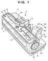
- Figure 1 is an external perspective view of a syringe pump 1 as an example of the drug infusion device, visibly showing an operation portion 12 as an infusion setting means for setting the flow rate and so on and a setting dial 6 ordinarily operated by a right hand.
- the syringe pump 1 is a minute amount sustained infusion pump for the purposes of drug solution infusions such as nutritional support, blood transfusion, chemotherapeutic drugs and anesthetics in ICU, CCU and NICU. Its operability is improved by providing a display portion 11 as display means to be adjacent to the operation portion 12 so as to roughly concentrate on a top surface as shown in Figure 1.
- the operation portion 12 and display portion 11 are totally covered with an embossed sheet cover, and have a drip-proof design to satisfy a drip-proof test of JIS0920. For instance, they are so highly drip-proof that a carelessly spilt drug solution and so on of the drug can be easily wiped off and inward infiltration thereof can be prevented.
- its upper and lower covers are integrally formed with a chemical-resistant molding resin material, and mutual bonding faces of the covers are screwed after putting a rubber seal made of silicon elastomer between them in order to prevent a foreign matter such as a liquid from coming in.
- an operation indicator 7 as warning means is provided by projecting upward at a position easily visible from the outside.
- the operation indicator 7 lights up, blinks and performs rotative indication in a plurality of colors such as red and green so that its operating state and warning state can be monitored even from a distance and so safety can be fully ensured.
- a buzzer is built in so that, when the setting beyond the upper and lower limits is performed by using the operation portion 12 or setting dial 6 in the case of setting one or both of the upper and lower limits of the flow rate on the continuous infusion and the upper and lower limits, time and flow rate on the one-shot administration as will be described later, it prompts the user to stop the infusion by the warning with sound and light in conjunction with the operation indicator 7.
- the warning function in which the safety is taken into consideration.
- It has a shape capable of multiple uses (simultaneous use of many pieces) and an easy-to-use design capable of buildup.
- Its geometry is a small size of height 110 mm ⁇ width 322 mm ⁇ depth 115 mm for instance, its weight is 1.6 kg or so, and its power sources are three systems of an AC commercial power, an internal battery and DC12VA.
- the internal battery requires charging time of 15 hours, and is covered with a cap and detachably provided by making a connector connection at a bottom of the lower cover so as to be easily replaceable from the outside. Its replacement life is three years or longer, and its charge control is trickle charge. Furthermore, over discharge and charge are prevented by cell breakage detection and cell breakage safety measures of a charge battery. And a heat-resistant (Ni-Cd) battery is used so that a brand new battery can operate for 120 minutes or longer until a warning occurrence and 150 minutes or longer until a shutdown.
- Ni-Cd heat-resistant
- a display portion 10 for gamma infusion, display portions 11 for the flow rate, planned amount and summed amount and so on are provided on an operation panel while the setting dial 6 is easily detachable for cleaning.
- syringe mounting means for setting a syringe 2 at the position indicated in the broken line as an example of the drug container is comprised of a syringe stage of the upper cover, a slit portion for setting the flange portion integrally formed with the syringe body, a clamp support (indicated in the broken line) for rotatively supporting a clamp 5 shown in the drawing, and a slider assembly 50 for setting the pusher of the syringe.
- the slider assembly 50 to be driven in a direction of an arrow A4 in the drawing is linked and fixed to a slider infuse mechanism at ends of a pipe shaft and an inner clutch shaft described later so as to reciprocate on a concave portion of a case. And it is possible to easily mount or remove the pusher of the syringe by manually operating a clutch lever 52 of the slider assembly 50.
- An external communication connector 22 is placed below the setting dial 6 so as to allow an external communication function mentioned later, such as the one by connecting to an external medical monitor to be performed for instance, and it is thereby possible to remotely control occlusion detection and motor driving.
- a nurse call connector 13 for a nurse call is placed adjacently to the external communication connector 22 so that an occurrence of an abnormal state can be notified to a nurse by connecting it to a nurse call connection terminal close to a bed on placing it in a hospital.
- the external communication connector 22 allows a doctor to erase and rewrite an identification tag 3 via a communication line by means of the external communication function so as to cope with rapid deterioration of the patient.
- the warning is given when the setting of the infusion is performed exceeding the drug or medicine data previously set on the identification tag 3, and the warning can be withdrawn in the event of an emergency.
- a power switch 15 an AC/DC lamp 16 and a battery lamp 17 are collectively placed on a left edge to prevent a malfunction.
- a syringe display lamp 18 is provided for the sake of, on setting the syringe 2 by using the clamp 5, converting a vertical travel distance of the clamp 5 into an electrical signal and then automatically measuring a syringe diameter to display a capacity of the set syringe of 10 cc (ml), 20 cc (ml), 30 cc (ml) or 50 cc (ml).
- the operation indicator 7 is made of a transparent acrylic resin, and lights and blinks a plurality of embedded light-emitting diodes appropriately shining in red and green and scatters light inside it as if rotating in the arrow direction shown in the drawing so as to electronically display an infusion operating state. And it blinks in red with the buzzer in the case where the infusion setting exceeds or drops below an allowable value.
- the display lamps Adjacently to the clamp 5, the display lamps (not shown) are provided for the sake of displaying by change-over in three stages a setting detection pressure by an occlusion detection mechanism provided to the syringe pump. A remaining amount alarm lamp, a battery alarm lamp (not shown) and so on are collectively placed adjacently to these lamps.
- the display portions 11 has a "7"-segment LED provided thereon, and has a display changeover switch 26 and a summation clear switch 27 provided on the right side thereof.
- the clamp 5 is raised to an upward arrow D3 and is turned in an arrow D4 direction by approximately 90 degrees in order to set the syringe 2.
- the clamp 5 held in a state of being fitted to a vertical projection of the clamp support can remain against an unshown pull strength at an upper end of the clamp support.
- a flange portion 2f of the syringe 2 has the identification tag 3 comprised of a magnetic chip as the identification tag, a barcode, a two-dimensional barcode and a rewritable and erasable IC chip fixed thereon. Otherwise, the identification tag 3 has the drug data on the drug accommodated or to be accommodated recorded thereon. To be more precise, the identification tag 3 has the drug data on the kind and concentration of the drug and both or one of the upper and lower limits of the flow rate on the continuous infusion and the upper and lower limits, time and flow rate on the one-shot administration recorded thereon by using a data input apparatus.
- the syringe having the drug accommodated in advance is referred to as a prefilled syringe.
- the flange portion 2f of the syringe 2 is set on the slit, electrical detection becomes possible by means of a reading portion 101 which is reading means placed at a position corresponding to the identification tag 3. Thereafter, if the syringe 2 is set on the syringe stage and then the clamp 5 is turned to an arrow D1, the locked state is released and it is pulled in an arrow D2 direction in the drawing to clamp the syringe 2 so that the setting of the container portion of the syringe is finished.
- the slider assembly 50 has an unshown slider infuse mechanism provided thereto, where the pusher 2P is pushed to infuse a drug solution and it moves in a direction opposite to an infuse direction on completion of the infusion operation so as to return to its initial position.
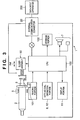
- FIG 3 is a block diagram of the syringe pump 1.
- a CPU 100 as control means has the respective means connected thereto, and the medicine and drug solution are fed under control of the CPU 100.
- a motor driver (not shown) which drives the slider assembly 50 for moving the pusher is connected and moves in the arrow A4 direction.
- the identification tag 3 fixed on the flange portion is optically and electromagnetically detected as digital data by the reading portion 101 which is the reading means so as to have the drug or medicine data read and stored in a storage portion 102.
- the operation portion 12 and setting dial 6 as the infusion setting means are connected to display setting results in the display portion 11.
- the operation indicator 7 and buzzer as the warning means are connected to call attention when a wrong setting is performed as mentioned later.
- the external communication connector 22 allows the external medical monitor or the data input apparatus 200 to be connected thereto so as to perform the external communication function and thereby remotely control the occlusion detection and motor driving.
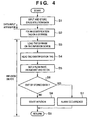
- FIG. 4 is a flowchart showing an operation example of the syringe pump of the above configuration.
- a step S1 first, the drug data on the drug accommodated or to be accommodated in the syringe 2 is recorded on the identification tag 3 as identification means by using the data input apparatus and stored thereon.
- the identification tag 3 is not fixed on the flange portion 2f of the syringe 2 in advance, it is fixed thereon in a step S2.
- the identification tag 3 uses one of the magnetic chip, barcode, two-dimensional barcode and rewritable and erasable IC chip, and the reading portion 101 is modified accordingly.
- a step S3 the syringe 2 is set as shown in Figure 2. If it is detected that the clamp 5 has been moved to a set position, it moves on to a step S4, so that the identification tag 3 is read by the reading portion 101 and read data is stored in the storage portion 102. Subsequently, the patient or the nurse performs the setting of one of the upper and lower limits of the flow rate on the continuous infusion and the upper and lower limits, time and flow rate on the one-shot administration by operating the operation portion 12 and setting dial 6.
- step S6 compares the set value set in a step S5 to the value stored in the storage portion 102. And if it is determined to be out of the stored data, it moves on to a step S7 to prompt for a change in the setting with the operation indicator 7 and buzzer, and returns in a step S9 to wait for resetting.
- step S6 As a result of the comparison to the value stored in the storage portion 102 in the step S6, if it is determined to be within the stored data, it moves on to a step S8 to start the infusion and then returns in the step S9.
- Figure 5A is an external view of the syringe 2 as an example of the drug container according to a second embodiment.
- Figure 5B is an external perspective view showing a relevant part after loading the syringe 2 on the syringe pump 1.
- a description will be omitted by giving the same symbols as to components already described.
- the syringe 2 is the prefilled syringe which is filled with a predetermined drug and sterilized in advance, and has a cap 32 for maintaining sterility provided to a delivery outlet so that the sterility is maintained by workings with a gasket 2g.
- the syringe 2 has the identification tag 3 fixed on a side 2a of its body by adhesion and so on, but the tag 3 may also be provided to either the flange portion 2f or the pusher 2P as with the preceding embodiment.
- the identification tag 3 is the tag wherein the IC chip connected to a loop antenna is specially printed on a base. And it does not have the power source itself but generates electric power by electromagnetic induction with a wave received by the loop antenna so as to drive a circuit by means of the power generation and thereby perform the reading and rewriting.
- a commuter pass for an automatic ticket gate of JR already put into practical use will be taken up.
- the identification tag 3 has the drug data on the kind and concentration of the drug and both or one of the upper and lower limits of the flow rate on the continuous infusion and the upper and lower limits, time and flow rate on the one-shot administration and so on stored thereon, the data on the time and flow rate, patients and health workers (one's doctor, nurse, pharmacist and so on) is rewritable, for instance.
- the syringe 2 thus prepared is sealed and delivered to a hospital and so on by a pharmaceutical manufacturer and so on after setting it in transparent or light-transmitting storage bag 30 having a drug label 33 recorded at an easy-to-see location.
- the nurse takes out the syringe 2 inside the bag thus provided by tearing it along a perforation 31, and loads it on the syringe pump by using the above-mentioned procedure so that the identification tag 3 faces downward as shown in Figure 5B. Consequently, the identification tag 3 stops at a position close to and opposed to a reading and rewriting portion 65 built in the syringe pump so as to be ready for the reading and rewriting.
- Figure 6 is an external perspective view showing the syringe pump 1, data input apparatus 200 and a dedicated apparatus 60 for the reading and rewriting.
- a connection cable 201 is connected between the external communication connector 22 of the syringe pump 1 and an external connector 210 of the data input apparatus 200 which is a notebook PC for instance.
- the doctor performs the reading of the drug data on the identification tag 3 and the reading and rewriting of the data on the time and flow rate, patients and health workers (one's doctor, nurse, pharmacist and so on) and so on.
- a specific health worker such as the doctor performs the reading of the drug or medicine data on the identification tag 3 and the reading and rewriting of the data on the time and flow rate, patients and health workers (one's doctor, nurse, pharmacist and so on) and so on after connecting the connection cable 201 between an external communication connector 61 of the dedicated apparatus 60 and the external connector 210 of the data input apparatus 200 and loading the syringe 2 in a state of being put in the storage bag 30 as shown in the drawing.
- the dedicated apparatus 60 is the apparatus dedicated to the reading and rewriting of the identification tag 3, and has the reading and rewriting portion 65 for having the power supplied and operating on connection to the external connector 210 which is a USB connector provided on a cap portion 63.
- the cap portion 63 is rotatively supported at the edge of a base 62, and is closed after setting it with the identification tag 3 of the syringe 2 facing upward as illustrated so that the identification tag 3 is located at the position close to and opposed to the reading and rewriting portion 65 to be ready for the reading and rewriting as described above.
- the dedicated apparatus 60 allows the data on the patients and health workers (one's doctor, nurse, pharmacist and so on) to be read and rewritten in the state of being put in the storage bag 30 and handled only by the specific health worker such as the doctor, so that it can be handed to the nurse to prevent a wrong setting as to a liquid infusing time and the flow rate on the site.
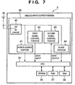
- FIG. 7 is a block diagram of the identification tag 3.
- the identification tag 3 is comprised of an analog input-output circuit 39 and a control portion (CPU) 35 which is a digital circuit.
- the analog input-output circuit 39 is connected with a radio frequency circuit (RF circuit) 40 which receives radio transmission of a predetermined frequency transmitted from the reading and rewriting portion 65 by being connected to a loop antenna 45.
- RF circuit radio frequency circuit
- the radio frequency circuit 40 is connected with a power source portion 41 for supplying a predetermined voltage to the CPU 35, a first signal control portion 42 for converting the read drug data to a digital signal and sending it to the CPU 35, a second signal control portion 43 for converting the digital signal on the time and flow rate sent from the CPU 35 to an analog signal and sending it to the radio frequency circuit 40, and a clock portion 44 for generating a clock signal to start up and drive the CPU 35.
- the CPU 35 is connected with a storage area (E2PROM) 36 which is a flash memory and is readable and rewritable by the specific health worker such as the doctor and an ROM 37 and an RAM 38 which are the storage areas non-rewritable by the specific health worker such as the doctor and capable of write setting only by the pharmaceutical and medical appliance manufacturers.
- E2PROM 36 is connected to the dedicated apparatus to rewriting 60 or the syringe pump 1, and stores the liquid infuding time, liquid infuding flow rate and so on which are set by using the data input apparatus 200.
- the ROM 37 as a non-rewritable first storage portion has drug information such as the drug data on the kind and concentration of the drug and both or one of the upper and lower limits of the flow rate on the continuous infusion and the upper and lower limits, time and flow rate on the one-shot administration and so on written and permanently stored thereon on manufacturing (shipment) thereof by the pharmaceutical and medical appliance manufacturers.
- the RAM 38 is used as the storage portion on signal processing and so on.
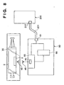
- FIG 8 is a block diagram showing the appearance after loading the syringe 2 in the storage bag 30 on the dedicated apparatus 60.
- the loop antenna 45 of the identification tag 3 is set opposite a loop antenna 46 connected to the reading and rewriting portion 65.
- the reading and rewriting portion 65 has the radio frequency circuit 40 built therein, and reads and rewrites the identification tag 3 by exchanging control signals sent from a signal control portion 66.
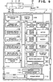
- FIG. 9 is a block diagram of the syringe pump 1 as an example of the drug infusion device.
- a control circuit 104 is connected to the CPU 100 as the control means.
- the control circuit 104 is connected to the loop antenna 46 connected to the reading and rewriting portion 65.
- the loop antenna 46 is placed opposite the loop antenna 45 of the identification tag 3 in the state of having the syringe 2 loaded as an example of the drug infusion device so as to read and rewrite the identification tag 3 by exchanging the control signals sent from the control circuit 104.
- the CPU 100 is connected with a syringe size detection circuit 105 for detecting an outside diameter of the syringe 2 by detecting the travel distance of the clamp 5 for the sake of setting the syringe 2, a remaining amount detection circuit 106 for detecting a remaining amount of the drug by detecting the travel distance of the pusher, an occlusion detection circuit 107 for detecting an occlusion state of a tube by detecting an increase in a pusher traveling force, and a pusher off clutch detection circuit 108 for detecting the pusher dropped off the slider assembly 50.
- a syringe size detection circuit 105 for detecting an outside diameter of the syringe 2 by detecting the travel distance of the clamp 5 for the sake of setting the syringe 2
- a remaining amount detection circuit 106 for detecting a remaining amount of the drug by detecting the travel distance of the pusher
- an occlusion detection circuit 107 for detecting an occlusion state of a tube by detecting an increase in a
- the CPU 100 is also connected with a switch and dial detection circuit 109 for detecting the set value set by operation of the switch and dial and sending it to the CPU 100, a power switch circuit 110 for detecting on and off of the power switch, a monitoring circuit 116 for monitoring the operation of the CPU 100, a motor driving circuit 118 for driving a motor 119 which drives the slider assembly 50, and a motor rotation detection circuit for measuring liquid infusing by detecting a rotation amount of the motor 119.
- a switch and dial detection circuit 109 for detecting the set value set by operation of the switch and dial and sending it to the CPU 100
- a power switch circuit 110 for detecting on and off of the power switch
- a monitoring circuit 116 for monitoring the operation of the CPU 100
- a motor driving circuit 118 for driving a motor 119 which drives the slider assembly 50
- a motor rotation detection circuit for measuring liquid infusing by detecting a rotation amount of the motor 119.
- the CPU 100 is connected with a buzzer driving circuit 120 for driving a buzzer 7, an LED display driving circuit 121 for driving an LED display portion 11a, a liquid crystal display driving circuit 122 for driving a liquid crystal portion 11b, a nurse call circuit 123 for calling the nurse in the case of an emergency by being connected to the external communication connector 22, and an external communication circuit 124 for rewriting the identification tag 3 by being connected to the data input apparatus 200 as described above.
- a power circuit 113 is connected with a power input connector 112 so that it has the power supplied from the commercial power and drives a charging circuit 114 to charge a charge battery 115 and supply the power to the power switch circuit 110.
- the power circuit 113 is further connected with a connector 111 for a DC power input so as to allow a drive by a DC power source.
- Figure 10 is a flowchart for describing the operation of loading the sterilized prefilled syringe 2 storing the drug in advance in the sterilized bag 30 on the dedicated apparatus 60 and rewriting the identification tag 3.
- a step S10 first, the dedicated apparatus 60 is connected to the data input apparatus 200 as shown in Figure 8. Subsequently, the data input apparatus 200 is started up in a step S11, and the prefilled syringe 2 in the storage bag 30 is set on the dedicated apparatus 60 in a step S12, and then a preinstalled prefilled syringe rewriting program is started up in a step S13. Then, the identification tag 3 is automatically read in a step S14, and reading results are displayed on the data input apparatus.
- the specific health worker such as the doctor refers to a drug record of the patient to whom the liquid infusing is performed in a step S15, and determines the data such as the liquid infusing time or the liquid infusing flow rate of the drug according to symptoms of the patient and so on, and inputs them together with the data on the patient and health workers (one's doctor, nurse, pharmacist and so on) by using a keyboard of the data input apparatus 200 and so on in a step S16. Consequently, the writing and rewriting are performed to the E2PROM 36 as a second storage portion capable of writing and rewriting the identification tag 3 in a step S17.
- a step S18 the rewriting is finished by removing the prefilled syringe 2 from the dedicated apparatus 60. Thereafter, the specific health worker such as the doctor hands the prefilled syringe 2 in the storage bag 30 to the nurse. The nurse takes the prefilled syringe 2 out of the storage bag 30, and sets it on the syringe pump to perform the liquid infusing to the patient. If the infusion of a predetermined amount of the drug is finished, the data on the patient and health workers (one's doctor, nurse, pharmacist and so on) and prescribed drug data (kinds and infusion amounts, etc. of the drug) are stored as curing (prescription) history in the storage portion.
- the data on the patient and health workers (one's doctor, nurse, pharmacist and so on) and the prescribed drug data (kinds and infusion amounts, etc. of the drug) are sent to a nurse center, a host computer in the hospital and so on as required via the external communication circuit 124 and the external communication connector 22 so as to be stored and displayed to be checked as required.
- the data input apparatus 200 is connected to the external communication connector 22 to rewrite the identification tag 3.
- the identification tag 3 it is possible to ensure the safety of the identification tag 3 by storing the drug data on the kind and concentration of the drug and both or one of the upper and lower limits of the flow rate on the continuous infusion and the upper and lower limits, time and flow rate on the one-shot administration in the ROM 37 (refer to Figure 7) and prompting for the stop of the infusion when the wrong setting is performed.
- the liquid infusing time and liquid infusing flow rate required to be set according to the symptoms of the patient they can be rewritten by storing them in the E2PROM 36 which is the flash memory. Therefore, it is possible to cope with the cases of performing the liquid infusing of a large amount or a small amount of the drug in a short time or performing the liquid infusing of a larger amount or a smaller amount of the drug for a long time.
Landscapes
- Health & Medical Sciences (AREA)
- Engineering & Computer Science (AREA)
- Biomedical Technology (AREA)
- Public Health (AREA)
- General Health & Medical Sciences (AREA)
- Epidemiology (AREA)
- Medical Informatics (AREA)
- Primary Health Care (AREA)
- Medicinal Chemistry (AREA)
- Bioinformatics & Cheminformatics (AREA)
- Chemical & Material Sciences (AREA)
- Business, Economics & Management (AREA)
- General Business, Economics & Management (AREA)
- Anesthesiology (AREA)
- Vascular Medicine (AREA)
- Heart & Thoracic Surgery (AREA)
- Hematology (AREA)
- Life Sciences & Earth Sciences (AREA)
- Animal Behavior & Ethology (AREA)
- Veterinary Medicine (AREA)
- Infusion, Injection, And Reservoir Apparatuses (AREA)
- Medical Preparation Storing Or Oral Administration Devices (AREA)
Abstract
Description
Claims (9)
- A drug container having an identification tag fixed or detachably provided at a predetermined position of the container, the tag having data on a drug accommodated or to be accommodated and so on recorded thereon, the container characterized in that the identification tag comprises:a first storage portion in which non-rewritable drug data including a kind of the drug and upper and lower limits of a flow rate on a continuous infusion and so on is recorded; anda second storage portion in which rewritable data including the data on a liquid infusing time and a liquid infusing flow rate and the data on a patient and health workers and so on is recorded.
- The drug container according to claim 1, characterized in that said identification tag is a magnetic chip for performing magnetic reading and rewriting or an integrated circuit chip for performing the reading and rewriting by driving a circuit by means of power generation through electromagnetic induction with a wave received by an antenna.
- The drug container according to claim 1 or 2, characterized in that said container is a syringe for infusing the liquid of the drug charged in advance by movement of a pusher, and said identification tag is fixed on a flange portion or a syringe body.
- A drug infusion device comprising the drug container according to claim 1 or 2, characterized by comprising:loading means for rendering said container detachably loadable and infusing the liquid;reading and rewriting means for reading and rewriting said drug data recorded on said identification tag after being loaded on said loading means;display means for displaying said read drug data;infusion setting means for having both or one of the upper and lower limits of the flow rate on the continuous infusion and the upper and lower limits, time and flow rate on a one-shot administration set by the user;warning means for giving warnings including a beep, a display and a vibration; andcontrol means, connected to each of the means, for operating said warning means when a setting by said infusion setting means is outside a range of the read drug data.
- A drug infusion device comprising the drug container according to claim 1 or 2, characterized by comprising:reading and rewriting means for loading said container detachably and reading and rewriting said drug data recorded on said identification tag after the loading; and connection means for connecting said reading and rewriting means to an external apparatus, andperforming said reading and rewriting by using said external apparatus.
- The drug infusion device comprising the drug container according to claim 5, characterized in that said reading and rewriting means performs said reading and rewriting in a state of accommodating said container in a sterilized bag.
- The drug infusion device comprising the drug container according to claim 3, characterized by comprising:syringe loading means for loading said syringe detachably and moving said pusher to infuse the liquid;reading and rewriting means for reading and rewriting said drug data recorded on said identification tag after the loading on said syringe loading means;display means for displaying said read drug data;infusion setting means for having both or one of upper and lower limits of a flow rate on a continuous infusion and upper and lower limits, time and flow rate on a one-shot administration set by a user;warning means for giving warnings including a beep, a display and a vibration; andcontrol means, connected to each of said means, for operating said warning means when a setting by said infusion setting means is outside a range of read drug data.
- The drug infusion device comprising the drug container according to claim 3, characterized by comprising:reading and rewriting means for loading said syringe detachably and reading and rewriting said drug data recorded on said identification tag after the loading; andconnection means for connecting said reading and rewriting means to an external apparatus, andperforming said reading and rewriting by using said external apparatus.
- The drug infusion device comprising the drug container according to claim 8, characterized in that said reading and rewriting means performs said reading and rewriting in a state of accommodating said syringe in a sterilized bag.
Applications Claiming Priority (3)
| Application Number | Priority Date | Filing Date | Title |
|---|---|---|---|
| JP2001276723 | 2001-09-12 | ||
| JP2001276723 | 2001-09-12 | ||
| PCT/JP2002/009257 WO2003024385A1 (en) | 2001-09-12 | 2002-09-11 | Medicine container and medicine injector comprising the same |
Publications (2)
| Publication Number | Publication Date |
|---|---|
| EP1433456A1 true EP1433456A1 (en) | 2004-06-30 |
| EP1433456A4 EP1433456A4 (en) | 2007-05-30 |
Family
ID=19101382
Family Applications (1)
| Application Number | Title | Priority Date | Filing Date |
|---|---|---|---|
| EP02765477A Withdrawn EP1433456A4 (en) | 2001-09-12 | 2002-09-11 | Medicine container and medicine injector comprising the same |
Country Status (4)
| Country | Link |
|---|---|
| US (1) | US7264148B2 (en) |
| EP (1) | EP1433456A4 (en) |
| JP (1) | JP4347692B2 (en) |
| WO (1) | WO2003024385A1 (en) |
Cited By (24)
| Publication number | Priority date | Publication date | Assignee | Title |
|---|---|---|---|---|
| DE102004046003A1 (en) * | 2004-09-17 | 2006-03-30 | Arzneimittel Gmbh Apotheker Vetter & Co. Ravensburg | Pharmaceutical package, as a syringe or vial or capsule, has an integrated microchip and antenna to give a unique and tamper-proof identity |
| EP1690559A1 (en) * | 2005-02-14 | 2006-08-16 | Ares Trading S.A. | Medication delivery device |
| EP1690560A1 (en) * | 2005-02-14 | 2006-08-16 | Ares Trading S.A. | Medication delivery device |
| EP1912131A1 (en) * | 2005-04-06 | 2008-04-16 | Mallinckrodt, Inc. | Systems and methods for managing information relating to medical fluids and containers therefor |
| WO2009087607A1 (en) * | 2008-01-11 | 2009-07-16 | Koninklijke Philips Electronics N.V. | Patient control of ventilation properties |
| WO2009097441A1 (en) | 2008-01-29 | 2009-08-06 | Cardinal Health 303, Inc. | Syringe imaging systems |
| CN100544782C (en) * | 2004-07-14 | 2009-09-30 | 株式会社根本杏林堂 | Chemical Liquid Injection System |
| AU2007216610B2 (en) * | 2005-04-06 | 2009-10-01 | Liebel-Flarsheim Company Llc | Systems and methods for managing information relating to medical fluids and containers therefor |
| EP2172237A1 (en) * | 2008-09-12 | 2010-04-07 | Delphi Technologies, Inc. | Electronic tag system |
| US7828776B2 (en) | 2005-04-11 | 2010-11-09 | Nemoto Kyorindo Co., Ltd. | Chemical liquid injection system |
| WO2011015228A1 (en) * | 2009-08-04 | 2011-02-10 | Stepra Ltd | An apparatus for verifying the identity of a final fluid product for medical or pharmaceutical use |
| US8075514B2 (en) | 2003-03-28 | 2011-12-13 | Carefusion 303, Inc. | Infusion data communication system |
| EP2327430A4 (en) * | 2008-09-12 | 2012-06-20 | K & Y Corp | Infusion pump system |
| US8211057B2 (en) | 2005-09-12 | 2012-07-03 | Nemoto Kyorindo Co., Ltd. | Chemical liquid injection system |
| US8552361B2 (en) | 2002-07-24 | 2013-10-08 | Deka Products Limited Partnership | Optical displacement sensor for infusion devices |
| CN101848742B (en) * | 2007-07-27 | 2013-11-06 | 里程碑科技有限公司 | Self-administration injection system |
| FR2990136A1 (en) * | 2012-05-02 | 2013-11-08 | Pharmadyne | KIT FOR RECHARGING AN INFUSION PUMP, METHOD OF PREPARING AND USING THE SAME |
| US8750967B2 (en) | 2009-04-09 | 2014-06-10 | Mallinckrodt Llc | Medical fluid delivery system with RFID-equipped wand |
| US8798979B2 (en) | 2005-05-11 | 2014-08-05 | Carefusion 303, Inc. | Infusion device data set analyzer |
| US9770549B2 (en) | 2009-04-08 | 2017-09-26 | Liebel-Flarsheim Company Llc | Reusable data storage fixtures for use with power injector syringe assemblies |
| EP2953088A4 (en) * | 2013-01-30 | 2018-01-03 | Sony Corporation | Information processing device and method, and program |
| EP2328634B1 (en) | 2008-06-11 | 2020-02-12 | Bracco Diagnostics Inc. | Infusion systems including computer-facilitated maintenance |
| CN111050823A (en) * | 2017-09-29 | 2020-04-21 | 泰尔茂株式会社 | Medical pump, method for controlling medical pump, and medical pump system |
| EP3777924A4 (en) * | 2018-03-29 | 2022-05-04 | TERUMO Kabushiki Kaisha | PRE-FILLED SYRINGE, LIQUID MEDICATION DELIVERY SYSTEM AND SYRINGE PUMP |
Families Citing this family (98)
| Publication number | Priority date | Publication date | Assignee | Title |
|---|---|---|---|---|
| US8565860B2 (en) * | 2000-08-21 | 2013-10-22 | Biosensors International Group, Ltd. | Radioactive emission detector equipped with a position tracking system |
| US8489176B1 (en) | 2000-08-21 | 2013-07-16 | Spectrum Dynamics Llc | Radioactive emission detector equipped with a position tracking system and utilization thereof with medical systems and in medical procedures |
| US8909325B2 (en) | 2000-08-21 | 2014-12-09 | Biosensors International Group, Ltd. | Radioactive emission detector equipped with a position tracking system and utilization thereof with medical systems and in medical procedures |
| JP2004313579A (en) * | 2003-04-18 | 2004-11-11 | Nemoto Kyorindo:Kk | Medical fluid filling device |
| DE10325106A1 (en) * | 2003-06-03 | 2004-12-30 | Disetronic Licensing Ag | Device and method for recognizing a user of a medical device |
| WO2005051285A1 (en) * | 2003-11-26 | 2005-06-09 | Nipro Corporation | Ic chip-equipped medical vessel |
| EP1689484B1 (en) * | 2003-11-26 | 2012-10-31 | Acist Medical Systems, Inc. | Device, method, and computer program product for dispensing media as part of a medical procedure |
| US9470801B2 (en) * | 2004-01-13 | 2016-10-18 | Spectrum Dynamics Llc | Gating with anatomically varying durations |
| EP1709585B1 (en) * | 2004-01-13 | 2020-01-08 | Spectrum Dynamics Medical Limited | Multi-dimensional image reconstruction |
| US8571881B2 (en) * | 2004-11-09 | 2013-10-29 | Spectrum Dynamics, Llc | Radiopharmaceutical dispensing, administration, and imaging |
| US9040016B2 (en) * | 2004-01-13 | 2015-05-26 | Biosensors International Group, Ltd. | Diagnostic kit and methods for radioimaging myocardial perfusion |
| US10964075B2 (en) | 2004-01-13 | 2021-03-30 | Spectrum Dynamics Llc | Gating with anatomically varying durations |
| US8586932B2 (en) | 2004-11-09 | 2013-11-19 | Spectrum Dynamics Llc | System and method for radioactive emission measurement |
| CN105641776B (en) * | 2004-03-03 | 2021-03-30 | 株式会社根本杏林堂 | Liquid medicine injection system, liquid medicine injection device and liquid medicine heat preservation device |
| JP4549079B2 (en) * | 2004-03-05 | 2010-09-22 | パナソニック株式会社 | Medical dosing device |
| EP1778957A4 (en) | 2004-06-01 | 2015-12-23 | Biosensors Int Group Ltd | OPTIMIZING THE MEASUREMENT OF RADIOACTIVE EMISSIONS IN SPECIFIC BODY STRUCTURES |
| JP4559150B2 (en) * | 2004-07-28 | 2010-10-06 | テルモ株式会社 | Syringe pump |
| JP4615926B2 (en) * | 2004-07-30 | 2011-01-19 | テルモ株式会社 | Wireless automatic recognition device (RFID) and automatic medicine recognition system |
| US8000773B2 (en) | 2004-11-09 | 2011-08-16 | Spectrum Dynamics Llc | Radioimaging |
| US10136865B2 (en) | 2004-11-09 | 2018-11-27 | Spectrum Dynamics Medical Limited | Radioimaging using low dose isotope |
| US8606349B2 (en) | 2004-11-09 | 2013-12-10 | Biosensors International Group, Ltd. | Radioimaging using low dose isotope |
| US9316743B2 (en) | 2004-11-09 | 2016-04-19 | Biosensors International Group, Ltd. | System and method for radioactive emission measurement |
| US8615405B2 (en) * | 2004-11-09 | 2013-12-24 | Biosensors International Group, Ltd. | Imaging system customization using data from radiopharmaceutical-associated data carrier |
| US9943274B2 (en) | 2004-11-09 | 2018-04-17 | Spectrum Dynamics Medical Limited | Radioimaging using low dose isotope |
| WO2008059489A2 (en) | 2006-11-13 | 2008-05-22 | Spectrum Dynamics Llc | Radioimaging applications of and novel formulations of teboroxime |
| WO2006118285A1 (en) | 2005-04-27 | 2006-11-09 | Seiko Epson Corporation | Fluid transport system and fluid discharge amount setting method |
| EP1909853B1 (en) * | 2005-07-19 | 2015-03-18 | Biosensors International Group, Ltd. | Imaging protocols |
| US8837793B2 (en) | 2005-07-19 | 2014-09-16 | Biosensors International Group, Ltd. | Reconstruction stabilizer and active vision |
| WO2007062315A2 (en) * | 2005-11-21 | 2007-05-31 | Acist Medical Systems, Inc. | Medical fluid injection system |
| JP2007185288A (en) * | 2006-01-12 | 2007-07-26 | Jms Co Ltd | Syringe pump |
| US20090054766A1 (en) * | 2006-03-14 | 2009-02-26 | Nemoto Kyorindo Co., Ltd. | Medical image system |
| JP4943728B2 (en) * | 2006-03-30 | 2012-05-30 | テルモ株式会社 | Blood glucose meter |
| JPWO2007116841A1 (en) * | 2006-04-04 | 2009-08-20 | 株式会社根本杏林堂 | Chemical injection system |
| JP5063591B2 (en) * | 2006-04-05 | 2012-10-31 | 株式会社根本杏林堂 | Chemical injection system |
| WO2007116864A1 (en) * | 2006-04-05 | 2007-10-18 | Nemoto Kyorindo Co., Ltd. | Medicinal-liquid injection system |
| JP5063590B2 (en) * | 2006-04-05 | 2012-10-31 | 株式会社根本杏林堂 | Chemical injection system |
| US8894974B2 (en) * | 2006-05-11 | 2014-11-25 | Spectrum Dynamics Llc | Radiopharmaceuticals for diagnosis and therapy |
| US7601966B2 (en) * | 2006-06-28 | 2009-10-13 | Spectrum Dynamics Llc | Imaging techniques for reducing blind spots |
| JP2010511430A (en) * | 2006-12-04 | 2010-04-15 | デカ・プロダクツ・リミテッド・パートナーシップ | Medical device including a slider assembly |
| WO2008075362A2 (en) | 2006-12-20 | 2008-06-26 | Spectrum Dynamics Llc | A method, a system, and an apparatus for using and processing multidimensional data |
| USD598548S1 (en) * | 2007-02-16 | 2009-08-18 | Nuclea Biomarkers, Llc | Stylet |
| JP5550901B2 (en) * | 2007-04-11 | 2014-07-16 | 株式会社根本杏林堂 | Chemical injection device, fluoroscopic imaging system, computer program |
| US8062008B2 (en) * | 2007-09-27 | 2011-11-22 | Curlin Medical Inc. | Peristaltic pump and removable cassette therefor |
| US7934912B2 (en) | 2007-09-27 | 2011-05-03 | Curlin Medical Inc | Peristaltic pump assembly with cassette and mounting pin arrangement |
| US8083503B2 (en) | 2007-09-27 | 2011-12-27 | Curlin Medical Inc. | Peristaltic pump assembly and regulator therefor |
| US8521253B2 (en) * | 2007-10-29 | 2013-08-27 | Spectrum Dynamics Llc | Prostate imaging |
| CN101977643A (en) | 2008-03-24 | 2011-02-16 | 奥林巴斯株式会社 | Medicinal-solution administration device |
| JP4798169B2 (en) * | 2008-05-13 | 2011-10-19 | セイコーエプソン株式会社 | Program for controlling discharge data processing apparatus |
| US9974904B2 (en) | 2008-05-20 | 2018-05-22 | Avant Medical Corp. | Autoinjector system |
| US8177749B2 (en) | 2008-05-20 | 2012-05-15 | Avant Medical Corp. | Cassette for a hidden injection needle |
| US8052645B2 (en) | 2008-07-23 | 2011-11-08 | Avant Medical Corp. | System and method for an injection using a syringe needle |
| US10089443B2 (en) | 2012-05-15 | 2018-10-02 | Baxter International Inc. | Home medical device systems and methods for therapy prescription and tracking, servicing and inventory |
| US8057679B2 (en) | 2008-07-09 | 2011-11-15 | Baxter International Inc. | Dialysis system having trending and alert generation |
| US20110137162A1 (en) * | 2008-08-19 | 2011-06-09 | Bruce John K | Power Injector with Syringe Communication Logic |
| EP2359881B1 (en) | 2008-12-16 | 2022-07-20 | PHC Holdings Corporation | Medication administering device |
| US8338788B2 (en) | 2009-07-29 | 2012-12-25 | Spectrum Dynamics Llc | Method and system of optimized volumetric imaging |
| JP4873061B2 (en) * | 2009-10-09 | 2012-02-08 | パナソニック株式会社 | Medical dosing device |
| AU2011208652B2 (en) * | 2010-01-22 | 2014-10-23 | Sanofi-Aventis Deutschland Gmbh | Method and system for determining information related to a drug reservoir |
| US9677555B2 (en) | 2011-12-21 | 2017-06-13 | Deka Products Limited Partnership | System, method, and apparatus for infusing fluid |
| US10391241B2 (en) | 2010-01-22 | 2019-08-27 | Deka Products Limited Partnership | Syringe pump having a pressure sensor assembly |
| US9789247B2 (en) | 2011-12-21 | 2017-10-17 | Deka Products Limited Partnership | Syringe pump, and related method and system |
| US9744300B2 (en) | 2011-12-21 | 2017-08-29 | Deka Products Limited Partnership | Syringe pump and related method |
| LT2699293T (en) | 2011-04-20 | 2019-04-25 | Amgen Inc. | Autoinjector apparatus |
| KR20140093999A (en) * | 2011-11-18 | 2014-07-29 | 사노피-아벤티스 도이칠란트 게엠베하 | Battery disconnection circuit |
| US10561787B2 (en) | 2011-12-21 | 2020-02-18 | Deka Products Limited Partnership | Syringe pump and related method |
| ES3075619T3 (en) | 2011-12-21 | 2026-08-06 | Deka Products Lp | System, method, and apparatus for electronic patient care |
| US11217340B2 (en) | 2011-12-21 | 2022-01-04 | Deka Products Limited Partnership | Syringe pump having a pressure sensor assembly |
| US12465684B2 (en) | 2011-12-21 | 2025-11-11 | Deka Products Limited Partneship | Apparatus for infusing fluid |
| US10088346B2 (en) | 2011-12-21 | 2018-10-02 | Deka Products Limited Partnership | System, method, and apparatus for monitoring, regulating, or controlling fluid flow |
| US9675756B2 (en) | 2011-12-21 | 2017-06-13 | Deka Products Limited Partnership | Apparatus for infusing fluid |
| US10563681B2 (en) | 2011-12-21 | 2020-02-18 | Deka Products Limited Partnership | System, method, and apparatus for clamping |
| CA2863788A1 (en) * | 2012-02-17 | 2013-08-22 | Pharmacophotonics, Inc. | Compositions and methods for monitoring biometric indicators |
| USD898908S1 (en) | 2012-04-20 | 2020-10-13 | Amgen Inc. | Pharmaceutical product cassette for an injection device |
| US9080707B2 (en) | 2013-02-12 | 2015-07-14 | Bayer Medical Care Inc. | Intelligent contrast warmer and contrast holder |
| US10492990B2 (en) | 2013-03-15 | 2019-12-03 | Amgen Inc. | Drug cassette, autoinjector, and autoinjector system |
| US10092703B2 (en) | 2013-03-15 | 2018-10-09 | Amgen Inc. | Drug cassette, autoinjector, and autoinjector system |
| USD767756S1 (en) | 2013-06-11 | 2016-09-27 | Deka Products Limited Partnership | Medical pump |
| USD735319S1 (en) | 2013-06-11 | 2015-07-28 | Deka Products Limited Partnership | Medical pump |
| USD736370S1 (en) | 2013-06-11 | 2015-08-11 | Deka Products Limited Partnership | Medical pump |
| USD760782S1 (en) | 2013-12-20 | 2016-07-05 | Deka Products Limited Partnership | Display screen of a medical pump with a graphical user interface |
| USD760888S1 (en) * | 2013-12-20 | 2016-07-05 | Deka Products Limited Partnership | Medical pump |
| US20150182698A1 (en) | 2013-12-31 | 2015-07-02 | Abbvie Inc. | Pump, motor and assembly for beneficial agent delivery |
| CA2959086C (en) | 2014-09-18 | 2023-11-14 | Deka Products Limited Partnership | Apparatus and method for infusing fluid through a tube by appropriately heating the tube |
| USD801519S1 (en) | 2015-02-10 | 2017-10-31 | Deka Products Limited Partnership | Peristaltic medical pump |
| USD803387S1 (en) | 2015-02-10 | 2017-11-21 | Deka Products Limited Partnership | Syringe medical pump |
| USD803386S1 (en) | 2015-02-10 | 2017-11-21 | Deka Products Limited Partnership | Syringe medical pump |
| USD805183S1 (en) | 2015-02-10 | 2017-12-12 | Deka Products Limited Partnership | Medical pump |
| JP2018524718A (en) | 2015-06-25 | 2018-08-30 | ガンブロ・ルンディア・エービーGambro Lundia Ab | Medical device system and method with distributed database |
| CN107192597B (en) * | 2016-03-15 | 2021-08-27 | 徕卡显微系统(上海)有限公司 | Paraffin distributor, embedding machine and control method and device of paraffin distributor |
| CN110100283B (en) | 2016-12-21 | 2023-07-04 | 甘布罗伦迪亚股份公司 | Medical device system including information technology infrastructure with secure cluster domain supporting external domain |
| JP7183169B2 (en) * | 2017-09-29 | 2022-12-05 | テルモ株式会社 | MEDICAL PUMP, METHOD OF CONTROLLING MEDICAL PUMP, AND MEDICAL PUMP SYSTEM |
| JPWO2019189451A1 (en) * | 2018-03-29 | 2021-03-18 | テルモ株式会社 | Prefilled syringe |
| MX2021001825A (en) | 2018-08-16 | 2021-07-15 | Deka Products Lp | Medical pump. |
| WO2020260297A1 (en) * | 2019-06-28 | 2020-12-30 | Becton Dickinson France | A plastic flange for a medical container, medical container including this plastic flange, and a method for manufacturing this medical container |
| JP7626420B2 (en) * | 2019-07-17 | 2025-02-04 | 株式会社テクトロン | Infusion Pump System |
| US20230321353A1 (en) * | 2020-12-02 | 2023-10-12 | Phc Holdings Corporation | Drug cartridge, cassette, drug injection device, and drug injection system |
| CA3251278A1 (en) * | 2021-10-06 | 2025-06-05 | Deka Products Limited Partnership | System for organ injection |
| CN117504047B (en) * | 2023-11-22 | 2024-07-23 | 首都医科大学宣武医院 | A micro pump system |
Family Cites Families (21)
| Publication number | Priority date | Publication date | Assignee | Title |
|---|---|---|---|---|
| US4978335A (en) | 1989-09-29 | 1990-12-18 | Medex, Inc. | Infusion pump with bar code input to computer |
| CA2125693C (en) * | 1992-10-15 | 2005-05-03 | Alan D. Ford | An infusion pump with an electronically loadable drug library |
| GB9309151D0 (en) * | 1993-05-04 | 1993-06-16 | Zeneca Ltd | Syringes and syringe pumps |
| GB9422082D0 (en) * | 1994-11-02 | 1994-12-21 | Zeneca Ltd | Reservoirs and delivery devices |
| JP3122584B2 (en) | 1994-11-29 | 2001-01-09 | 株式会社湯山製作所 | Drug container identification device |
| US5772635A (en) | 1995-05-15 | 1998-06-30 | Alaris Medical Systems, Inc. | Automated infusion system with dose rate calculator |
| JPH08333009A (en) | 1995-06-08 | 1996-12-17 | Yuyama Seisakusho:Kk | Method and apparatus for managing drug inventory by transponder |
| JPH09319727A (en) * | 1996-05-31 | 1997-12-12 | Hitachi Ltd | Data processor and data processing system |
| JPH1119210A (en) | 1997-07-09 | 1999-01-26 | Terumo Corp | Chemical solution injection system and its readable memory |
| AU9104498A (en) * | 1997-08-22 | 1999-03-16 | Deka Products Limited Partnership | System and method for intelligent admixture and delivery of medications |
| US20050101905A1 (en) * | 1997-09-03 | 2005-05-12 | Safer Sleep Limited | Coding of syringes to monitor their use |
| JPH11259583A (en) | 1998-03-10 | 1999-09-24 | Tosho:Kk | Spatial transmission network system for dispensing medical care information |
| EP1087808B1 (en) | 1998-06-15 | 2003-12-03 | Medrad Inc. | Encoding of syringe information |
| JP2001134151A (en) | 1999-11-05 | 2001-05-18 | Yoshikawa Rf System Kk | Consumables management system for electronic device, data carrier for cartridge, and consumables management method for electronic device |
| AU2001223396A1 (en) * | 2000-02-01 | 2001-08-14 | Disetronic Licensing Ag | Container and device for administering a substance |
| GB0004456D0 (en) * | 2000-02-26 | 2000-04-19 | Glaxo Group Ltd | Medicament dispenser |
| JP3639923B2 (en) * | 2000-03-07 | 2005-04-20 | シャープ株式会社 | Image forming apparatus |
| US8055509B1 (en) * | 2000-03-10 | 2011-11-08 | Walker Digital, Llc | Methods and apparatus for increasing and/or for monitoring a party's compliance with a schedule for taking medicines |
| US6435175B1 (en) * | 2000-08-29 | 2002-08-20 | Sensormedics Corporation | Pulmonary drug delivery device |
| JP4022709B2 (en) | 2000-09-27 | 2007-12-19 | オムロン株式会社 | Medical information processing system and medical information processing method |
| JP2002172150A (en) * | 2000-12-06 | 2002-06-18 | Toppan Printing Co Ltd | Tagged pharmaceutical package and method for preventing erroneous administration of pharmaceutical |
-
2002
- 2002-09-11 US US10/489,334 patent/US7264148B2/en not_active Expired - Lifetime
- 2002-09-11 EP EP02765477A patent/EP1433456A4/en not_active Withdrawn
- 2002-09-11 JP JP2003528284A patent/JP4347692B2/en not_active Expired - Fee Related
- 2002-09-11 WO PCT/JP2002/009257 patent/WO2003024385A1/en not_active Ceased
Cited By (64)
| Publication number | Priority date | Publication date | Assignee | Title |
|---|---|---|---|---|
| US8552361B2 (en) | 2002-07-24 | 2013-10-08 | Deka Products Limited Partnership | Optical displacement sensor for infusion devices |
| US8075514B2 (en) | 2003-03-28 | 2011-12-13 | Carefusion 303, Inc. | Infusion data communication system |
| CN100544782C (en) * | 2004-07-14 | 2009-09-30 | 株式会社根本杏林堂 | Chemical Liquid Injection System |
| DE102004046003A1 (en) * | 2004-09-17 | 2006-03-30 | Arzneimittel Gmbh Apotheker Vetter & Co. Ravensburg | Pharmaceutical package, as a syringe or vial or capsule, has an integrated microchip and antenna to give a unique and tamper-proof identity |
| NO343778B1 (en) * | 2005-02-14 | 2019-06-03 | Ares Trading Sa | Medicine delivery device, method for determining drug doses and computer program |
| EP1690560A1 (en) * | 2005-02-14 | 2006-08-16 | Ares Trading S.A. | Medication delivery device |
| EP1690559A1 (en) * | 2005-02-14 | 2006-08-16 | Ares Trading S.A. | Medication delivery device |
| US8323234B2 (en) | 2005-02-14 | 2012-12-04 | Ares Trading Sa | Medication delivery device |
| US8137304B2 (en) | 2005-02-14 | 2012-03-20 | Ares Trading Sa | Medication delivery device |
| WO2006085204A1 (en) * | 2005-02-14 | 2006-08-17 | Ares Trading S.A. | Medication delivery device |
| US8043254B2 (en) | 2005-02-14 | 2011-10-25 | Ares Trading Sa | Medication delivery device |
| WO2006085175A1 (en) * | 2005-02-14 | 2006-08-17 | Ares Trading S.A. | Medication delivery device |
| CN101107029B (en) * | 2005-02-14 | 2011-06-01 | 阿瑞斯贸易股份公司 | Medication delivery device |
| EA010333B1 (en) * | 2005-02-14 | 2008-08-29 | Арес Трейдинг С.А. | Medication delivery device, a method for determining medication doses, a method for determining amount of medication, and computer program therefor |
| EP2110150A1 (en) * | 2005-02-14 | 2009-10-21 | Ares Trading S.A. | Medication delivery device |
| US7975922B2 (en) | 2005-04-06 | 2011-07-12 | Mallinckrodt Inc. | Systems and methods for managing information relating to medical fluids and containers therefor |
| EP1912140A1 (en) * | 2005-04-06 | 2008-04-16 | Mallinckrodt, Inc. | Systems and methods for managing information relating to medical fluids and containers therefor |
| EP1912131A1 (en) * | 2005-04-06 | 2008-04-16 | Mallinckrodt, Inc. | Systems and methods for managing information relating to medical fluids and containers therefor |
| AU2007216610B2 (en) * | 2005-04-06 | 2009-10-01 | Liebel-Flarsheim Company Llc | Systems and methods for managing information relating to medical fluids and containers therefor |
| US9082157B2 (en) | 2005-04-06 | 2015-07-14 | Liebel-Flarsheim Company Llc | Systems and methods for managing information relating to medical fluids and containers therefor |
| EP1912141A1 (en) * | 2005-04-06 | 2008-04-16 | Mallinckrodt, Inc. | Systems and methods for managing information relating to medical fluids and containers therefor |
| US7698180B2 (en) | 2005-04-06 | 2010-04-13 | Mallinckrodt Inc. | System for tracking data relating to radiopharmaceuticals and/or containers therefor |
| AU2007216593B2 (en) * | 2005-04-06 | 2010-08-26 | Liebel-Flarsheim Company Llc | Systems and methods for managing information relating to medical fluids and containers therefor |
| AU2006231575B2 (en) * | 2005-04-06 | 2010-09-02 | Liebel-Flarsheim Company Llc | Systems and methods for managing information relating to medical fluids and containers therefor |
| US8446280B2 (en) | 2005-04-06 | 2013-05-21 | Mallinckrodt Llc | Systems and methods for managing information relating to medical fluids and syringes therefor |
| AU2007216603B2 (en) * | 2005-04-06 | 2010-12-02 | Liebel-Flarsheim Company Llc | Systems and methods for managing information relating to medical fluids and containers therefor |
| US7859473B2 (en) | 2005-04-06 | 2010-12-28 | Mallinckrodt Inc. | Systems and methods for managing information relating to medical fluids and containers therefor |
| US7588189B2 (en) | 2005-04-06 | 2009-09-15 | Mallinckrodt Inc. | Systems and methods for managing information relating to medical fluids and containers therefor |
| US7898416B2 (en) | 2005-04-06 | 2011-03-01 | Mallinckrodt Inc. | Systems and methods for managing information relating to medical fluids and containers therefor |
| CN101185781B (en) * | 2005-04-06 | 2011-04-06 | 马林克罗特公司 | Systems and methods for managing information relating to medical fluids and containers therefor |
| EP1914651A1 (en) * | 2005-04-06 | 2008-04-23 | Mallinckrodt, Inc. | Systems and methods for managing information relating to medical fluids and containers therefor |
| US7963936B2 (en) | 2005-04-06 | 2011-06-21 | Mallinckrodt Inc. | Systems and methods for managing information relating to medical fluids and containers therefor |
| EP1912138A1 (en) * | 2005-04-06 | 2008-04-16 | Mallinckrodt, Inc. | Systems and methods for managing information relating to medical fluids and containers therefor |
| US8035517B2 (en) | 2005-04-06 | 2011-10-11 | Mallinckrodt LLC. | Systems and methods for managing information relating to medical fluids and containers therefor |
| EP1912133A1 (en) * | 2005-04-06 | 2008-04-16 | Mallinckrodt, Inc. | Systems and methods for managing information relating to medical fluids and containers therefor |
| EP1912143A1 (en) * | 2005-04-06 | 2008-04-16 | Mallinckrodt, Inc. | Systems and methods for managing information relating to medical fluids and containers therefor |
| EP1912142A1 (en) * | 2005-04-06 | 2008-04-16 | Mallinckrodt, Inc. | Systems and methods for managing information relating to medical fluids and conntainers therefor |
| US7828776B2 (en) | 2005-04-11 | 2010-11-09 | Nemoto Kyorindo Co., Ltd. | Chemical liquid injection system |
| US8798979B2 (en) | 2005-05-11 | 2014-08-05 | Carefusion 303, Inc. | Infusion device data set analyzer |
| US8211057B2 (en) | 2005-09-12 | 2012-07-03 | Nemoto Kyorindo Co., Ltd. | Chemical liquid injection system |
| EP1932556A4 (en) * | 2005-09-12 | 2014-05-28 | Nemoto Kyorindo Co Ltd | Medicinal liquid injection system |
| CN101848742B (en) * | 2007-07-27 | 2013-11-06 | 里程碑科技有限公司 | Self-administration injection system |
| WO2009087607A1 (en) * | 2008-01-11 | 2009-07-16 | Koninklijke Philips Electronics N.V. | Patient control of ventilation properties |
| US9550037B2 (en) | 2008-01-11 | 2017-01-24 | Koninklijke Philips N.V. | Patient control of ventilation properties |
| US8161810B2 (en) | 2008-01-29 | 2012-04-24 | Carefusion 303, Inc. | Syringe imaging systems |
| WO2009097441A1 (en) | 2008-01-29 | 2009-08-06 | Cardinal Health 303, Inc. | Syringe imaging systems |
| EP2328634B1 (en) | 2008-06-11 | 2020-02-12 | Bracco Diagnostics Inc. | Infusion systems including computer-facilitated maintenance |
| EP2172237A1 (en) * | 2008-09-12 | 2010-04-07 | Delphi Technologies, Inc. | Electronic tag system |
| US9119915B2 (en) | 2008-09-12 | 2015-09-01 | Sims | Infusion pump system |
| EP2327430A4 (en) * | 2008-09-12 | 2012-06-20 | K & Y Corp | Infusion pump system |
| US9770549B2 (en) | 2009-04-08 | 2017-09-26 | Liebel-Flarsheim Company Llc | Reusable data storage fixtures for use with power injector syringe assemblies |
| US8750967B2 (en) | 2009-04-09 | 2014-06-10 | Mallinckrodt Llc | Medical fluid delivery system with RFID-equipped wand |
| CN105582592A (en) * | 2009-04-09 | 2016-05-18 | 利贝尔-弗拉施姆有限公司 | Medical fluid delivery system with RFID-equipped wand |
| CN105582592B (en) * | 2009-04-09 | 2019-05-31 | 利贝尔-弗拉施姆有限公司 | Medical fluid delivery system with the stick equipped with radio frequency identification |
| US8881980B2 (en) | 2009-08-04 | 2014-11-11 | STEPRA Ltd. | Apparatus for verifying the identity of a final fluid product for medical or pharmaceutical use |
| WO2011015228A1 (en) * | 2009-08-04 | 2011-02-10 | Stepra Ltd | An apparatus for verifying the identity of a final fluid product for medical or pharmaceutical use |
| EP2659921A3 (en) * | 2012-05-02 | 2015-10-21 | Pharmadyne | Kit for recharging an infusion pump with drug reservoir and detachable label |
| FR2990136A1 (en) * | 2012-05-02 | 2013-11-08 | Pharmadyne | KIT FOR RECHARGING AN INFUSION PUMP, METHOD OF PREPARING AND USING THE SAME |
| EP2953088A4 (en) * | 2013-01-30 | 2018-01-03 | Sony Corporation | Information processing device and method, and program |
| CN111050823A (en) * | 2017-09-29 | 2020-04-21 | 泰尔茂株式会社 | Medical pump, method for controlling medical pump, and medical pump system |
| EP3636300A4 (en) * | 2017-09-29 | 2020-05-27 | Terumo Kabushiki Kaisha | MEDICAL PUMP, CONTROL METHOD FOR MEDICAL PUMP, AND MEDICAL PUMP SYSTEM |
| CN111050823B (en) * | 2017-09-29 | 2022-10-21 | 泰尔茂株式会社 | Medical pump, method for controlling medical pump, and medical pump system |
| US11617830B2 (en) | 2017-09-29 | 2023-04-04 | Terumo Kabushiki Kaisha | Medical pump, method of controlling medical pump, and medical pump system |
| EP3777924A4 (en) * | 2018-03-29 | 2022-05-04 | TERUMO Kabushiki Kaisha | PRE-FILLED SYRINGE, LIQUID MEDICATION DELIVERY SYSTEM AND SYRINGE PUMP |
Also Published As
| Publication number | Publication date |
|---|---|
| WO2003024385A1 (en) | 2003-03-27 |
| EP1433456A4 (en) | 2007-05-30 |
| JP4347692B2 (en) | 2009-10-21 |
| US20050029277A1 (en) | 2005-02-10 |
| US7264148B2 (en) | 2007-09-04 |
| JPWO2003024385A1 (en) | 2004-12-24 |
Similar Documents
| Publication | Publication Date | Title |
|---|---|---|
| US7264148B2 (en) | Drug container and drug infusion device comprising the same | |
| JP4615926B2 (en) | Wireless automatic recognition device (RFID) and automatic medicine recognition system | |
| US10376634B2 (en) | Portable infusion pump and media player | |
| US20230055072A1 (en) | Flow Sensor System with Connection Assembly | |
| EP2155288B1 (en) | Removable controller for an infusion pump | |
| US9480793B2 (en) | Occlusion sensing for an infusion pump | |
| US8685002B2 (en) | Data storage for an infusion pump system | |
| JP2008080036A (en) | Medical pump | |
| US20100325864A1 (en) | Infusion Pump System with Contamination-Resistant Features | |
| US20120218740A1 (en) | Illumination Instrument for an Infusion Pump | |
| JP7162604B2 (en) | MEDICAL PUMP, METHOD OF CONTROLLING MEDICAL PUMP, AND MEDICAL PUMP SYSTEM | |
| WO2021085135A1 (en) | Medical pump, method for controlling medical pump, and medical pump system | |
| JP5881299B2 (en) | Medical pump | |
| JP4405737B2 (en) | Syringe pump |
Legal Events
| Date | Code | Title | Description |
|---|---|---|---|
| PUAI | Public reference made under article 153(3) epc to a published international application that has entered the european phase |
Free format text: ORIGINAL CODE: 0009012 |
|
| 17P | Request for examination filed |
Effective date: 20040401 |
|
| AK | Designated contracting states |
Kind code of ref document: A1 Designated state(s): AT BE BG CH CY CZ DE DK EE ES FI FR GB GR IE IT LI LU MC NL PT SE SK TR |
|
| AX | Request for extension of the european patent |
Extension state: AL LT LV MK RO SI |
|
| RIN1 | Information on inventor provided before grant (corrected) |
Inventor name: TACHIBANA, YASUHARUC/O TERUMO KABUSHIKI KAISHA |
|
| A4 | Supplementary search report drawn up and despatched |
Effective date: 20070426 |
|
| RIC1 | Information provided on ipc code assigned before grant |
Ipc: G01N 35/00 20060101ALI20070420BHEP Ipc: A61M 5/145 20060101ALI20070420BHEP Ipc: G06F 19/00 20060101AFI20070420BHEP |
|
| 17Q | First examination report despatched |
Effective date: 20091228 |
|
| STAA | Information on the status of an ep patent application or granted ep patent |
Free format text: STATUS: THE APPLICATION IS DEEMED TO BE WITHDRAWN |
|
| 18D | Application deemed to be withdrawn |
Effective date: 20150602 |