EP1432246B1 - Verfahren und Gerät zur Dekodierung und zur Rückwärtsanzeige von MPEG-Bildern, Pilotvideoschaltung und ein ein solches Gerät enthaltender Dekoder - Google Patents
Verfahren und Gerät zur Dekodierung und zur Rückwärtsanzeige von MPEG-Bildern, Pilotvideoschaltung und ein ein solches Gerät enthaltender Dekoder Download PDFInfo
- Publication number
- EP1432246B1 EP1432246B1 EP03293014A EP03293014A EP1432246B1 EP 1432246 B1 EP1432246 B1 EP 1432246B1 EP 03293014 A EP03293014 A EP 03293014A EP 03293014 A EP03293014 A EP 03293014A EP 1432246 B1 EP1432246 B1 EP 1432246B1
- Authority
- EP
- European Patent Office
- Prior art keywords
- image
- images
- decoding
- stream
- displayed
- Prior art date
- Legal status (The legal status is an assumption and is not a legal conclusion. Google has not performed a legal analysis and makes no representation as to the accuracy of the status listed.)
- Expired - Lifetime
Links
- 238000000034 method Methods 0.000 title claims description 48
- 230000015654 memory Effects 0.000 claims description 142
- 239000000872 buffer Substances 0.000 claims description 28
- 230000008569 process Effects 0.000 claims description 25
- 230000004044 response Effects 0.000 claims description 3
- 230000000694 effects Effects 0.000 claims description 2
- 230000001747 exhibiting effect Effects 0.000 claims 3
- 230000001502 supplementing effect Effects 0.000 claims 2
- 102100037812 Medium-wave-sensitive opsin 1 Human genes 0.000 description 17
- 230000004907 flux Effects 0.000 description 16
- 230000006870 function Effects 0.000 description 4
- 230000033001 locomotion Effects 0.000 description 3
- 240000008042 Zea mays Species 0.000 description 2
- 230000002457 bidirectional effect Effects 0.000 description 2
- 238000004364 calculation method Methods 0.000 description 2
- 238000010586 diagram Methods 0.000 description 2
- 241000590419 Polygonia interrogationis Species 0.000 description 1
- 241001080024 Telles Species 0.000 description 1
- 230000005540 biological transmission Effects 0.000 description 1
- 210000004027 cell Anatomy 0.000 description 1
- 238000013144 data compression Methods 0.000 description 1
- 230000006837 decompression Effects 0.000 description 1
- 230000001934 delay Effects 0.000 description 1
- 229940082150 encore Drugs 0.000 description 1
- 239000012530 fluid Substances 0.000 description 1
- 230000004807 localization Effects 0.000 description 1
- 238000007726 management method Methods 0.000 description 1
- 230000007246 mechanism Effects 0.000 description 1
- 238000011144 upstream manufacturing Methods 0.000 description 1
- 238000012795 verification Methods 0.000 description 1
Images


Classifications
-
- H—ELECTRICITY
- H04—ELECTRIC COMMUNICATION TECHNIQUE
- H04N—PICTORIAL COMMUNICATION, e.g. TELEVISION
- H04N5/00—Details of television systems
- H04N5/76—Television signal recording
- H04N5/78—Television signal recording using magnetic recording
- H04N5/782—Television signal recording using magnetic recording on tape
- H04N5/783—Adaptations for reproducing at a rate different from the recording rate
-
- H—ELECTRICITY
- H04—ELECTRIC COMMUNICATION TECHNIQUE
- H04N—PICTORIAL COMMUNICATION, e.g. TELEVISION
- H04N5/00—Details of television systems
- H04N5/76—Television signal recording
- H04N5/78—Television signal recording using magnetic recording
- H04N5/781—Television signal recording using magnetic recording on disks or drums
-
- H—ELECTRICITY
- H04—ELECTRIC COMMUNICATION TECHNIQUE
- H04N—PICTORIAL COMMUNICATION, e.g. TELEVISION
- H04N5/00—Details of television systems
- H04N5/76—Television signal recording
- H04N5/84—Television signal recording using optical recording
- H04N5/85—Television signal recording using optical recording on discs or drums
-
- H—ELECTRICITY
- H04—ELECTRIC COMMUNICATION TECHNIQUE
- H04N—PICTORIAL COMMUNICATION, e.g. TELEVISION
- H04N9/00—Details of colour television systems
- H04N9/79—Processing of colour television signals in connection with recording
- H04N9/80—Transformation of the television signal for recording, e.g. modulation, frequency changing; Inverse transformation for playback
- H04N9/804—Transformation of the television signal for recording, e.g. modulation, frequency changing; Inverse transformation for playback involving pulse code modulation of the colour picture signal components
- H04N9/8042—Transformation of the television signal for recording, e.g. modulation, frequency changing; Inverse transformation for playback involving pulse code modulation of the colour picture signal components involving data reduction
Definitions
- the present invention relates to the decoding and display of audiovisual programs contained in a stream of compressed digital data.
- DSM digital mass storage medium
- the decoders concerned are in particular set-top boxes, which provide the interface between the arrival of digital signals broadcast in real time by satellite, cable or terrestrial digital broadcasting (or DVB). "Digital Video Broadcasting" on the one hand, and an analog TV on the other.
- Such a set-top box is a stand-alone device.
- the invention also applies to decoders integrated in a digital television, or a digital reading / recording device such as a DVD player, a digital video cassette player ("Digital Video Cassette Recorder”), or the like .
- a set-top box receives one or more programs in the form of a compressed digital data stream, i.e. whose video frames (ie, frames) and audio frames are coded so as to reduce the volume of disseminated data.
- this coding complies with the specifications of the MPEG-2 standard (ISO / IEC 13818-2) hereinafter MPEG standard ("Motion Pictures Expert Group").
- MPEG-2 ISO / IEC 13818-2
- MPEG standard Motion Pictures Expert Group
- the term "presentation”, when used in connection with a program, designates the reproduction of the decoded audio and video data, in the form respectively audible and visible by a user.
- the term “playback”("playback” in English), used in connection with a program, refers more specifically to the decoding and display of the program from a recording of the program on a hard drive.
- the term “display”("display” in English) is more particularly used to designate the presentation of video frames.
- the hard disk provides a number of features, including the implementation of advanced reading modes ("trick modes" in English), that is to say a reading at a speed different from a speed nominal (x1) forward. These include fast forward (fast forward) and fast reverse (“rewind”) playback.
- the MPEG stream is, by nature, adapted to a reading in forward. Indeed, the images are transmitted in an order intended to facilitate the decoding in the forward direction. For reverse reading, this transmission order requires the availability of computing resources having a decoding speed sufficient to perform all the decoding operations necessary for decoding each image. Otherwise, it is necessary to have a large storage capacity to store all the decoded images (ie, the image data after decompression) from the beginning of a group of images ("Group Of Pictures" or GOP ) within the meaning of the MPEG standard, since the images from the beginning of the GOP can again be used to decode a subsequent image in the GOP.
- This storage capacity is provided by frame memories, each of which is adapted to store the data of a decoded picture.
- EP-A-0 735 780 it is proposed a technique of reading in reverse of an MPEG video stream using the same number of frame memories as for reading forward. This number is equal to three. Nevertheless, the method consists in skipping the images B, and in decoding only three I or P images at the most, and then moving on to the previous GOP (in the order of display in the forward direction) as soon as this number is reached.
- EP-A-1 005 226 and EP-A-1,003,339 also describe other reverse reading techniques using three frame memories.
- An object of the invention is, among others, to propose management rules for optimizing the use of the frame memories available for the reverse display of images of an MPEG video stream, in particular a stream MPEG video, stored on the hard disk of a set-top box.
- the total number of decoding operations to be performed is limited to display the images in reverse.
- N the number of the frame memories
- one of the frame memories is used to store the image being displayed, and of the other three, one can be used to receive the uncompressed data from the image to decode and the other two to store at most two reference images necessary for this purpose (if the image to be decoded is a picture B).
- the allocation of frame memories dynamically evolves in a non-deterministic manner.
- the type I images have a first determined decoding cost; the P-type images predicted from a type I image have a second decoding cost, higher than said first decoding cost; and the P-type images predicted from another P-type image have a decoding cost higher than the decoding cost of said other P-type image.
- the cost of decoding a predicted image P from n reference images is equal to n + 1.
- the type B images have the same decoding cost as the I images, because they are only decoded at the time of their display and can be overwritten immediately after (since an image B is not a reference image for decoding another image).
- a next image to be displayed is checked before decoding, if it is not already stored in any of the frame memories. In this case indeed, it is useless to decode it again.
- the method may comprise steps of determining at each image display timing event whether the frame memories contain an image ready for display.
- Such an event corresponds for example to a pulse of the vertical synchronization signal (Vsync signal) of the screen of an analog television.
- An image ready for display is understood to mean a decoded image which follows, in the order of display of images in reverse, images which have already been displayed. If such an image is present then it is displayed, and it is marked as obsolete after the display if it is no longer necessary to perform an image decoding, that is to say if it is not a reference image for another image to be decoded / displayed.
- the compressed data stream is read in portions from a digital mass storage medium, for example a hard disk, in response to a read command in progress. back.
- a digital mass storage medium for example a hard disk
- a group of decodable images is a group of consecutive images of the stream that can be decoded without needing to know other images than those of the group (except for the images constituting what is called a broken link ("Broken Link" ) Typically such a group corresponds to a GOP, although a GOP may sometimes contain more than one such group of decodable images
- An access point in the sense of the MPEG standard, is an I-picture from from which it is possible to decode a group of images coming in the stream.
- the method comprises, between step b) and step c), assigning to each of the images encoded in said first portion of the flow of a unique identification number to uniquely identify it in the stream.
- the identification numbers are assigned to the images coded in the stream sequentially, according to the order of display of the images.
- the aforementioned PTS are used.
- step d) the next image to be displayed in reverse not yet decoded can be determined from its identification number, by counting the identification numbers.
- the identification number of the images is coded on 32 bits, and is initialized to the value h0x800000 (that is to say 0x800000 in hexadecimal notation) and is respectively incremented or decremented by one unit depending on whether one is browsing. flow in forward or reverse. Thus, it allows the reading in forward or reverse, several hours of video.
- the images of its reconstruction list are sequentially decoded not from the access point of the decodable group of images but from said already stored image, or, if appropriate, from those of said already stored images that have the highest decoding cost. This avoids performing again decoding operations that have already been done and the result is still available in the frame memories.
- the buffer memory comprises a first and a second bank of memory. Steps d) and e) are performed in said first memory bank for a first portion of the buffer stream, while steps a) to c) are performed in said second memory bank for a second portion of the stream.
- the decoding process is thus more fluid.
- the buffer is loaded so that the data stored in one or the other of the first and second banks of memory are not overwritten in step a) as long as these data are still necessary for the processing of the data contained therein. in the other of said first and second banks of memory.
- the data stored in one or the other of the first and second banks of memory are overwritten with a new portion of the stream, in step a), as soon as these data are no longer necessary for the processing of the data contained in the other of said first and second banks of memory. This loses a minimum amount of time before it can begin the decoding process for a subsequent portion of the stream.
- the flow portions loaded in the first bank of memory and in the second bank of memory overlap, a junction between these two portions can be made between the two stream portions at a common image. This is particularly advantageous when the stream is scrambled. Indeed, it is impossible to bend the data stream exactly between two images.
- indexing table can then advantageously be common for the two portions of flow.
- a second aspect of the invention relates to a device comprising means for implementing the above method.
- a third aspect of the invention relates to a video driver circuit ("Video Driver" in English) comprising a device according to the second aspect.
- Set Top Box comprising a video driver circuit according to the third aspect.
- images form elementary groups that are decodable independently of other elementary groups.
- a group of images that is to say a GOP, within the meaning of the MPEG standard may contain several of these elementary groups. In fact, however, it turns out that a GOP includes at most one elementary group. Bidirectional B-images can be interpolated between images of these elementary groups, thus constituting a broken link in the sense of the norm.
- Direct access points associated with start codes characterize the beginning of these elementary groups.
- the figure 1 schematically shows a device for implementing the method according to the invention.
- the method starts upon receipt of a command to read in reverse images contained in the stream 7 stored on the hard disk 1.
- the buffer memory 2 is loaded with a first portion 31 ( figure 1 ) These images are available in their order of recording on the hard disk and no information on the images including their location in this portion 31 is available at this stage (it is assumed that the demultiplexing / descrambling was performed upstream, otherwise an intermediate step of demultiplexing / descrambling must be added).
- the stream portion 31 is analyzed using the analyzer module 8, in particular to determine information including the position of the start codes of the elementary groups, the starting address of the images in the buffer 2, for each image a time stamp associated with a display order in forward, and type I, P or B of each of the images encoded in said first portion of flux.
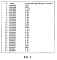
- This information is stored in an indexing table such as 11 ( figure 1 ).
- An example of an indexing table resulting from the implementation of step 22 is given by the table of the figure 3 . It corresponds to a stream portion 31 from a satellite broadcast; the asterisk on the images 2, 14 and 26 indicates the presence of a start code in these images corresponding to the beginning of a basic group.
- the buffer memory 2 here contains 28 images (numbered here from 0 to 27 for ease of identification).
- the image n ° 27 is not complete: only the beginning of the data which codes it has been extracted from the flow 7.
- the table contains the address in the buffer of the beginning of the image, the type I, P or B and the timestamp of the image in the group.
- the images are identified by their type I, B or P and by their order number of display in forward movement in the elementary group (ie for the example considered from 0 to 11); thus 11, which has been diffused in the stream before B0, is a type I picture which will be displayed (in a forward display order) before the type B picture identified by B2 and before the type picture.
- each image of the stream is assigned a unique identifier.
- This is for example a 32-bit number (the initialization value being for example h0x80000000) increasing according to the display order in forward.
- the initialization value being for example h0x80000000
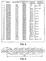
- step 23 An example of the result of step 23 implemented on the content of the indexing table 11 considered previously and illustrated on the figure 3 , is illustrated by the table of the figure 4 whose position column gives the address of the beginning of each image in the buffer memory, the second column indicates the image type and the display sequence number in the corresponding elementary group, the third column indicates the assigned unique identifier represented in its decimal form for more readability, the fourth and fifth columns indicate the reference images respectively anterior and posterior of the P and B type images.
- the table indicates that the reference images P3 of identifier 65522 and P5 of identifier 65524 are necessary.
- Question marks indicate that the information is not available; the symbol N indicates that no data is needed.
- the last step (step 25) consists, once the decompressed data of B4 of identifier 65523 thus obtained, to display this picture.
- the display and decoding steps are done in parallel. In practice, however, the display can only take place at a user-controlled nominal display rate when the image to be displayed has been decoded. In case of decoding delay, the display device therefore continues to display the image being displayed until the next image to be displayed is available. Moreover, the decoding can be carried out in advance of phase on the next images to be displayed, insofar as the resources in memory and the speed of the decoder allow it.
- steps 241 and 242 may, if the memory resources and the decoder speed allow, be implemented to decode the P9 ID image 65528 then B8 of identifier 65527, then P7 of identifier 65526 and keep them available to the display device.
- frame memories 5 In order to store the decompressed data of the decoded images used during the decoding and display phases, a certain number of frame memories 5 are used. One of these frame memories is used to collect the data of the current image. the others are used for decoding the next image to be displayed. In an ideal case, the individually decodable element being an elementary group, it would require as many frame memories as images in an elementary group, generally between 12 and 24.
- the figure 5 represents a list of images referenced in the indexing table represented on the table of the figure 4 .
- a number of these images constitute a GOP.
- the arrows represent how P and B type images are predicted, the arrows pointing from a reference image to the corresponding predicted image. So reference images B2 are P3 and 11, B4 are P3 and P5, B6 are P5 and P7; the reference image of P3 is 11, that of P5 is P3 etc.
- the decoding costs for the images I1, P3, P5, P7, P9, P11 are respectively 1, 2, 3, 4, 5 and 6. the decoding cost of a type B image is 1.
- the display module displays the next image to be displayed if it is available, otherwise it waits for it to be decoded by the decoder.
- the decoder decodes the next images to be displayed in advance of the display, as long as all the images identified in step 22 are not ready to be displayed, and as long as frame memories are available to do so, otherwise it waits until a frame memory can be used.
- the goal is to decode and display the image I1 of identifier 65532 to the image B4 of identifier 65511; the display speed is the speed x1 and the number of frame memories is equal to 4.
- the frame memories respectively named T1, T2, T3, T4 respectively contain the images I1 of identifier 65520 (T1), P5 of identifier 65524 ( T2), P3 of identifier 65522 (T3) and I1 of identifier 65532 (T4), and that the next image to be displayed is the image P11 of identifier 65530 (the image of identifier 65531 not being complete ).
- the purpose of the decoding is to obtain the image P11 of identifier 65530 which has not yet been decoded, then the images to be displayed thereafter as frame memories are available.
- the decoding is started from P5 of identifier 65524 which is available in frame memory T2.
- I1 is overwritten with identifier 65520 which is the non-currently displayed image having the lowest decoding cost to decode P7 of identifier 65526.
- P5 is decoded with identifier 65528 which is of the same type. way is stored in T3 by overwriting P3 identifier 65522, which is then the image not yet displayed having the lowest decoding cost.
- P11 is then decoded with identifier 65530 stored in T2, overwriting P5 with identifier 65524 for the same reasons.
- the P11 image of ID 65530 can be displayed.
- the image I1 of identifier 65532 is no longer displayed and is no longer a reference image for a next image to be displayed; it can be overwritten.
- the next image to display is B10 ID 65529, decoded from P9 and P11 that are available respectively in the frame memories T2 and T3.
- the reconstruction list of B10 contains only one image, namely itself. So B10 is stored in T4 instead of I1 waiting for the next synchronization of the vertical sync signal.
- the next image to be decoded is P9 of identifier 65528, available in the frame memory T2.
- the next image to decode is then B8, decoded from P9 and P7.
- the rebuild list contains only one image: itself.
- the memories T1, T2, T3, T4 respectively contain the images P7, P9, P11 and B10 and it is P11 which is being displayed. No frame memory is available to store B10. It is therefore necessary to wait for the next vertical synchronization to decode this image, which will be stored in the frame memory T3.
- this step 22 comparing the contents of the two sub-memories to ensure that said first and second portions of the stream are consecutive, and the indexing table for the first portion of the stream in the first sub-memory is completed and updated with the new information relating to the second portion of the stream, while the information relating to the images already displayed and no longer used thereafter are erased.
- a single indexing table is thus considered and contains useful information concerning the two portions of the flow considered.
- the two portions of the stream may partially overlap, in order to find a common image on which the junction can be made, which makes it possible to circumvent the difficulty of achieving accurate splitting of the flow.
- This is advantageous, especially for a scrambled data stream.
- Each of the portions of the data stream is replaced again only once that all the images contained in said portion could be displayed and is no longer necessary for the decoding of the images contained in the other portion.
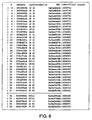
- the figure 6 illustrates the contents of an indexing table of a first sub-memory on which the decoding process takes place while a new portion of flow illustrated by the figure 7 is loaded in the other sub-memory, this new portion of the stream corresponding to the following display images in reverse display order.
- the last image of the new portion is not complete but it is not problematic because this image is always available as the first image of the other portion.
- the junction between the two flux portions is made at this image.
- step 22 is performed by updating the indexing list from which the images of the first portion of streams that have already been decoded and displayed have been removed: the resulting list is illustrated by the table of the figure 8 .
- each sub-memory can be for example between 512 kilobytes and 1 Megabytes, which allows them to store at least one GOP.
- the method set forth above provides methods for optimally decoding all images to be displayed in reverse. Some portions of streams, for example those having many predicted images and few direct access points would however, to be decoded in full, both a very large allocated memory capacity and a very fast decoder.
- the invention therefore proposes decision criteria resulting in the non-decoding and therefore the non-display of certain stream portions.
- the portions are considered non-decodable and the buffers are then loaded with new stream portions.
- the image concerned is discarded from the decoding and also the images from this image (identified in steps 22 and 23) if it is an image I or P.
- the decoder has a relatively slow speed and provides the decoded picture P11 with a certain delay with respect to the display speed, during which the device freezes the image I1. So instead of decoding the image B10 of identifier 65529, it will go directly to the decoding of the image P9 of identifier 65528.
Landscapes
- Engineering & Computer Science (AREA)
- Multimedia (AREA)
- Signal Processing (AREA)
- Television Signal Processing For Recording (AREA)
- Compression Or Coding Systems Of Tv Signals (AREA)
- Television Systems (AREA)
- Signal Processing For Digital Recording And Reproducing (AREA)
- Indexing, Searching, Synchronizing, And The Amount Of Synchronization Travel Of Record Carriers (AREA)
Claims (34)
- Verfahren zum Dekodieren und zum Rückwärtsanzeigen von Bildern eines Flusses von Daten von nach dem MPEG-2-Standard komprimierten Bildern unter Verwendung einer bestimmten Anzahl N von Rahmenspeichern, von denen jeder angepasst ist, um ein dekodiertes Bild zu speichern, wobei N eine Ganzzahl größer oder gleich 4 ist, wobei der Fluss von Daten kodierte Bilder des Typs I und kodierte Bilder des Typs P und B umfasst,
dadurch gekennzeichnet, dass die folgenden Regeln angewendet werden, wenn ein in einem Rahmenspeicher gespeichertes Bild überschrieben werden muss, um dem Speicher zu ermöglichen, dass ein neues Bild dekodiert wird:Überschreiben zunächst der Daten eines Rahmenspeichers, in dem ein obsoletes Bild gespeichert ist, d.h. ein Bild, welches bereits angezeigt wurde und welches nicht mehr benötigt wird, um eine nächste Dekodierung eines Bildes durchzuführen; oderÜberschreiben zunächst der Daten eines Rahmenspeichers, in dem ein Bild gespeichert ist, welches minimale Dekodierungskosten darstellt, wobei die Dekodierungskosten entsprechend der Anzahl von Referenzbilder berechnet werden, die für die Dekodierung des Bildes notwendig ist;die Daten eines Rahmenspeichers, in dem ein Bild gespeichert ist, welches gerade angezeigt wird, können nicht überschrieben werden;die Daten eines Rahmenspeichers, in dem ein Bild gespeichert ist, welches zum Anzeigen bereit ist, aber noch nicht angezeigt wurde, können nicht überschrieben werden;die Daten eines Rahmenspeichers, in dem ein Referenzbild gespeichert ist, das für die Dekodierung des zu dekodierenden neuen Bildes benötigt wird, können auch nicht überschrieben werden;falls die Daten keines Rahmenspeichers unter Anwendung der vorstehenden Regeln nicht überschrieben werden können, wird die Dekodierung bis zur Anzeige eines für die Anzeige bereiten Bildes unterbrochen, und diese Regeln werden nach dieser Anzeige erneut bewertet. - Verfahren nach Anspruch 1, wobei die Bilder des Typs I bestimmte erste Dekodierungskosten darstellen, wobei die Bilder des Typs P, die von einem Bild des Typs I prognostiziert wurden, zweite Dekodierungskosten darstellen, die höher als die ersten Dekodierungskosten sind, und wobei die Bilder des Typs P, die von einem anderen Bild des Typs P prognostiziert wurden, Dekodierungskosten darstellen, die höher als die Dekodierungskosten des anderen Bildes des Typs P sind.
- Verfahren nach Anspruch 2, wobei die Bilder des Typs B die ersten Dekodierungskosten darstellen.
- Verfahren nach einem der vorstehenden Ansprüche, wobei verifiziert wird, ob ein zu dekodierendes neues Bild nicht bereits in irgendeinen der Rahmenspeicher gespeichert wurde, bevor das neue Bild dekodiert wird.
- Verfahren nach einem der vorstehenden Ansprüche, ferner mit den folgenden Schritten:Bestimmen bei jedem Synchronisationsereignis einer Bildanzeige, ob ein für die Anzeige bereites Bild in den Rahmenspeichern vorliegt;falls dem so ist, Anzeigen des Bildes und Markieren des Bildes als obsolet, falls es zum Durchführen einer Bilddekodierung nicht mehr benötigt wird;und falls dem nicht so ist, Wiederholen der Anzeige des Bildes, das bei dem Synchronisationsereignis einer vorangegangenen Bildanzeige angezeigt wird.
- Verfahren nach einem der vorstehenden Ansprüche, wobei der Fluss von komprimierten Daten in Teilen von einem digitalen Massespeicher im Ansprechen auf einen Befehl eines Rückwärtslesens gelesen wird.
- Verfahren nach einem der vorstehenden Ansprüche, ferner mit den folgenden Schritten:a) Laden (21) eines Teils des Flusses in einen Pufferspeicher;b) Analysieren (22) des Teils des Flusses, um einen Zugangspunkt einer dekodierbaren Gruppe von Bildern zu identifizieren und zumindest für jedes der Bilder der Gruppe Informationen einschließlich der Adresse des Bildes in dem Pufferspeicher, einen mit einer Reihenfolge einer Vorwärtsanzeige des Bildes verknüpften Zeitstempel einer Präsentation, und den Typ I, P oder B des Bildes zu bestimmen, und Speichern der Informationen in eine Indexierungstabelle;c) Erhalten einer erweiterten Indexierungstabelle durch Vervollständigen der im Schritt b) erhaltenen Indexierungstabelle durch Spezifizieren, für jedes Bild des Typs P oder B, seines oder seiner Referenzbilder;d) Bestimmen von der Indexierungstabelle für ein anzuzeigendes nächstes Bild, einer Rekonstruktionsliste, welche eine Liste ist, die zu dekodierende Referenzbilder von dem Zugangspunkt sequentiell anordnet, um das anzuzeigende nächste Bild zu erhalten;e) Erhalten von der Rekonstruktionsliste des anzuzeigenden nächsten Bildes durch Dekodieren aller oder eines Teils der Bilder der Rekonstruktionsliste.
- Verfahren nach Anspruch 7, ferner mit dem folgenden Schritt zwischen den Schritten b) und c):Zuordnen (23) zu jedem der kodierten Bilder in dem ersten Teil des Flusses einer alleinigen Identifikationsnummer, die eine eindeutige Identifizierungsweise in dem Fluss zulässt.
- Verfahren nach Anspruch 8, wobei im Schritt d) das anzuzeigende nächste Bild von seiner Identifikationsnummer bestimmt wird (25).
- Verfahren nach einem der Ansprüche 7 bis 9, wobei zum Erhalten des anzuzeigenden nächsten Bildes verifiziert wird, ob zumindest eines der Bilder der Rekonstruktionsliste, das mit dem anzuzeigenden nächsten Bild verknüpft ist, nicht bereits in irgendeinem der Rahmenspeicher gespeichert wurde, und wobei, wenn dem so ist, mit der sequentiellen Dekodierung der Bilder der Liste nicht von dem Zugangspunkt der dekodierbaren Gruppe von Bildern, sondern von dem bereits gespeicherten Bild, oder gegebenenfalls von den bereits gespeicherten Bildern, welche die höchsten Dekodierungskosten darstellen, begonnen wird.
- Verfahren nach einem der Ansprüche 7 bis 10, wobei jedes Mal, wenn ein Bild angezeigt wird, eine Verzögerung bezüglich einer theoretischen Anzeigegeschwindigkeit berechnet wird, und wobei im Schritt d) das anzuzeigende nächste Bild derart bestimmt wird, dass die Verzögerung durch Überspringen der Bilder nach den folgenden Prioritätsregeln aufgehoben wird:Überspringen zunächst eines oder mehrerer Bilder des Typs B;falls ein oder mehrere übersprungene Bilder des Typs B nicht ausreichen, um die Verzögerung aufzuheben, werden ein oder mehrere Bilder des Typs P übersprungen;falls ein oder mehrere übersprungene Bilder des Typs P nicht ausreichen, um die Verzögerung aufzuheben, werden ein oder mehrerer Teile des Flusses von Daten während des Ladens in Schritt a) eines nächsten Teils des Flusses von Daten in den Pufferspeicher übersprungen.
- Verfahren nach einem der Ansprüche 7 bis 11, wobei der Pufferspeicher eine erste und eine zweite Speicherbank aufweist, und wobei die Schritte d) und e) in der ersten Speicherbank des Pufferspeichers für einen ersten Teil des Flusses realisiert werden, während die Schritte a) bis c) in der zweiten Speicherbank des Pufferspeichers für einen zweiten Teil des Flusses realisiert werden.
- Verfahren nach Anspruch 12, wobei die in der einen oder der anderen der ersten und zweiten Speicherbank gespeicherten Daten in Schritt a) nicht überschrieben werden, solange diese Daten für die Verarbeitung der in der anderen der ersten und zweiten Speicherbank enthaltenen Daten noch benötigt werden.
- Verfahren nach Anspruch 12 oder 13, wobei die in der einen oder der anderen der ersten und zweiten Speicherbank gespeicherten Daten mit einem neuen Teil des Flusses in Schritt a) überschrieben werden, sobald diese Daten für die Verarbeitung der in der anderen der ersten und zweiten Speicherbank enthaltenen Daten nicht mehr benötigt werden.
- Verfahren nach einem der Ansprüche 12 bis 14, wobei sich die in die erste Speicherbank und in die zweite Speicherbank geladenen Teile des Flusses überlappen, und wobei eine Verbindung zwischen diesen beiden Teilen einen Fluss auf dem Pegel eines gewöhnlichen Bildes zwischen den beiden Teilen realisieren kann.
- Verfahren nach Anspruch 12 bis 15, wobei die Indexierungstabellen relativ zu jedem der in die erste Speicherbank und in die zweite Speicherbank geladenen Teile des Flusses eine einzelne Indexierungstabelle darstellen.
- Vorrichtung zur Dekodierung und zur Rückwärtsanzeige von Bildern eines Flusses von Daten von nach dem MPEG-2-Standard komprimierten Bildern mit einer bestimmten Anzahl N von Rahmenspeichern, von denen jeder angepasst ist, um ein dekodiertes Bild zu speichern, wobei N eine Ganzzahl größer oder gleich 4 ist, wobei der Fluss von Daten kodierte Bilder des Typs I und kodierte Bilder des Typs P und B umfasst,
dadurch gekennzeichnet, dass sie Einrichtungen zum Anwenden der folgenden Regeln umfasst, wenn ein in einem Rahmenspeicher gespeichertes Bild überschrieben werden muss, um dem Speicher zu ermöglichen, dass ein neues Bild dekodiert wird:Überschreiben zunächst der Daten eines Rahmenspeichers, in dem ein Bild gespeichert ist, welches bereits angezeigt wurde, und welches nicht mehr benötigt wird, um eine Dekodierung eines Bildes durchzuführen; oderÜberschreiben zunächst der Daten eines Rahmenspeichers, in dem ein Bild gespeichert ist, welches minimale Dekodierungskosten darstellt, wobei die Dekodierungskosten entsprechend der Anzahl von Referenzbildern berechnet wird, die für die Dekodierung des Bildes benötigt wird;die Daten eines Rahmenspeichers, in dem ein Bild gespeichert ist, welches gerade angezeigt wird, können nicht überschrieben werden;die Daten eines Rahmenspeichers, in dem ein Bild gespeichert ist, welches zur Anzeige bereit ist, aber noch nicht angezeigt wurde, können nicht überschrieben werden;die Daten eines Rahmenspeichers, in dem ein Referenzbild gespeichert ist, das für die Dekodierung des zu dekodierenden neuen Bildes benötigt wird, können auch nicht überschrieben werden;falls die Daten keines Rahmenspeichers unter Anwendung der vorstehenden Regeln nicht überschrieben werden können, wird die Dekodierung bis zur Anzeige eines für die Anzeige bereiten Bildes unterbrochen, und diese Regeln werden nach dieser Anzeige erneut bewertet. - Vorrichtung nach Anspruch 17, ferner mit Einrichtungen zum Berechnen der Kosten bei der Dekodierung von Bilddaten, wobei die Bilder des Typs I bestimmte erste Dekodierungskosten darstellen, wobei die Bilder des Typs P, die von einem Bild des Typs I prognostiziert wurden, zweite Dekodierungskosten darstellen, die höher als die ersten Dekodierungskosten sind, und wobei die Bilder des Typs P, die von einem anderen Bild des Typs P prognostiziert wurden, Dekodierungskosten darstellen, die höher als die Dekodierungskosten des anderen Bildes des Typs P sind.
- Vorrichtung nach Anspruch 18, wobei die Einrichtungen zum Berechnen von Kosten bei der Dekodierung die ersten Dekodierungskosten für die Bilder des Typs B aufbringen.
- Vorrichtung nach einem der Ansprüche 17 bis 19, ferner mit Einrichtungen zum Verifizieren, dass ein zu dekodierendes neues Bild nicht bereits in irgendeinen der Rahmenspeicher gespeichert wurde, bevor das neue Bild dekodiert wird.
- Vorrichtung nach einem der Ansprüche 17 bis 20, ferner mit Einrichtungen zum
Bestimmen bei jedem Synchronisationsereignis einer Bildanzeige, ob ein für die Anzeige bereites Bild in den Rahmenspeichern vorliegt;
falls dem so ist, Anzeigen des Bildes und Markieren des Bildes als obsolet, falls es zum Durchführen einer Bilddekodierung nicht mehr benötigt wird;
und falls dem nicht so ist, Wiederholen der Anzeige des Bildes, das bei dem Synchronisationsereignis einer vorangegangenen Bildanzeige angezeigt wird. - Vorrichtung nach einem der Ansprüche 17 bis 21, ferner mit Einrichtungen zum Lesen des Flusses von komprimierten Daten in Teilen von einem digitalen Massespeicher im Ansprechen auf einen Befehl eines Rückwärtslesens.
- Vorrichtung nach einem der Ansprüche 17 bis 22, ferner mit:a) Einrichtungen zum Laden eines Teils des Flusses in einen Pufferspeicher;b) Einrichtungen zum Analysieren des Teils des Flusses, um einen Zugangspunkt einer dekodierbaren Gruppe von Bildern zu identifizieren, und zumindest für jedes der Bilder der Gruppe Informationen einschließlich der Adresse des Bildes in dem Pufferspeicher, einen mit einer Reihenfolge einer Vorwärtsanzeige des Bildes verknüpften Zeitstempel einer Präsentation, und den Typ I, P oder B des Bildes zu bestimmen, und Speichern der Informationen in eine Indexierungstabelle;c) Einrichtungen zum Erhalten einer erweiterten Indexierungstabelle durch Vervollständigen der im Schritt b) erhaltenen Indexierungstabelle durch Spezifizieren, für jedes Bild des Typs P oder B, seines oder seiner Referenzbilder;d) Einrichtungen zum Bestimmen von der Indexierungstabelle für ein anzuzeigendes nächstes Bild einer Rekonstruktionsliste, welche eine Liste ist, die zu dekodierende Referenzbilder von dem Zugangspunkt sequentiell anordnet, um das anzuzeigende nächste Bild zu erhalten;e) Einrichtungen zum Erhalten von der Rekonstruktionsliste des anzuzeigenden nächsten Bildes durch Dekodieren aller oder eines Teils der Bilder der Rekonstruktionsliste.
- Vorrichtung nach Anspruch 23, wobei die Einrichtungen zum Zuordnen der Identifikationsnummern zu den kodierten Bildern in dem Fluss die Nummern in sequentieller Weise gemäß der Reihenfolge einer Anzeige der Bilder zuordnen.
- Vorrichtung nach Anspruch 24, wobei die Einrichtungen zum Bestimmen das anzuzeigende nächste Bild anhand seiner Identifikationsnummer bestimmt.
- Vorrichtung nach einem der Ansprüche 23 bis 25, wobei die Einrichtungen zum Erhalten des anzuzeigenden nächsten Bildes Einrichtungen zum Verifizieren umfassen, ob zumindest eines der Bilder der Rekonstruktionsliste, das mit dem anzuzeigenden nächsten Bild verknüpft ist, nicht bereits in irgendeinem der Rahmenspeicher gespeichert wurde, und wobei, wenn dem so ist, mit einer sequentiellen Dekodierung der Bilder der Liste nicht von dem Zugangspunkt der dekodierbaren Gruppe von Bildern, sondern von dem bereits gespeicherten Bild, oder gegebenenfalls von den bereits gespeicherten Bildern, welche die höchsten Dekodierungskosten darstellen, begonnen wird.
- Vorrichtung nach einem der Ansprüche 23 bis 26, ferner mit Einrichtungen zum Berechnen einer Verzögerung bezüglich einer theoretischen Anzeigegeschwindigkeit, jedes Mal, wenn ein Bild angezeigt wird, und Einrichtungen zum Bestimmen des anzuzeigenden nächsten Bildes derart, dass die Verzögerung durch Überspringen der Bilder nach den folgenden Prioritätsregeln aufgehoben wird:Überspringen zunächst eines oder mehrerer Bilder des Typs B;falls ein oder mehrere übersprungene Bilder des Typs B nicht ausreichen, um die Verzögerung aufzuheben, werden ein oder mehrere Bilder des Typs P übersprungen;falls ein oder mehrere übersprungene Bilder des Typs P nicht ausreichen, um die Verzögerung aufzuheben, werden ein oder mehrere Teile des Flusses von Daten während des Ladens eines nächsten Teils des Flusses von Daten in den Pufferspeicher übersprungen.
- Vorrichtung nach einem der Ansprüche 23 bis 27, wobei der Pufferspeicher eine erste und eine zweite Speicherbank aufweist, und wobei die Einrichtungen zum Ändern und die Einrichtungen zum Analysieren in der ersten Speicherbank des Pufferspeichers für einen ersten Teil des Flusses betrieben werden, während die Einrichtungen zum Erhalten der Indexierungstabelle und die Einrichtungen zum Erhalten des anzuzeigenden nächsten Bildes in der zweiten Speicherbank des Pufferspeichers für einen zweiten Teil des Flusses betrieben werden.
- Vorrichtung nach Anspruch 28, ferner mit Einrichtungen zum Verhindern eines Überschreibens der in der einen oder der anderen der ersten und zweiten Speicherbank gespeicherten Daten, solange diese Daten für die Verarbeitung der in der anderen der ersten und zweiten Speicherbank enthaltenen Daten noch benötigt werden.
- Vorrichtung nach Anspruch 28 oder 29, ferner mit Einrichtungen zum Überschreiben der in der einen oder der anderen der ersten und zweiten Speicherbank gespeicherten Daten mit einem neuen Teil des Flusses in Schritt a), sobald diese Daten für die Verarbeitung der in der anderen der ersten und zweiten Speicherbank enthaltenen Daten nicht mehr benötigt werden.
- Vorrichtung nach einem der Ansprüche 28 bis 30, ferner mit Einrichtungen, damit sich die in die erste Speicherbank und in die zweite Speicherbank geladenen Teile des Flusses überlappen, und damit eine Verbindung zwischen diesen beiden Teilen auf dem Pegel eines gewöhnlichen Bildes realisiert werden kann.
- Vorrichtung nach Ansprüchen 28 bis 31, ferner mit Einrichtungen zum Vereinen der Indexierungstabellen relativ zu jedem der in die erste Speicherbank und in die zweite Speicherbank geladenen Flussteile in einer einzelnen Indexierungstabelle.
- Pilotvideoschaltung mit einer Vorrichtung nach einem der Ansprüche 17 bis 32.
- Dekoder mit einer Pilotvideoschaltung nach Anspruch 33.
Applications Claiming Priority (2)
| Application Number | Priority Date | Filing Date | Title |
|---|---|---|---|
| FR0216328A FR2849332A1 (fr) | 2002-12-20 | 2002-12-20 | Procede et dispositif et decodage et d'affichage en marche arriere d'images mpeg, circuit pilote video et boitier decodeur incorporant un tel dispositif |
| FR0216328 | 2002-12-20 |
Publications (2)
| Publication Number | Publication Date |
|---|---|
| EP1432246A1 EP1432246A1 (de) | 2004-06-23 |
| EP1432246B1 true EP1432246B1 (de) | 2010-05-26 |
Family
ID=32338983
Family Applications (1)
| Application Number | Title | Priority Date | Filing Date |
|---|---|---|---|
| EP03293014A Expired - Lifetime EP1432246B1 (de) | 2002-12-20 | 2003-12-02 | Verfahren und Gerät zur Dekodierung und zur Rückwärtsanzeige von MPEG-Bildern, Pilotvideoschaltung und ein ein solches Gerät enthaltender Dekoder |
Country Status (5)
| Country | Link |
|---|---|
| US (1) | US7430361B2 (de) |
| EP (1) | EP1432246B1 (de) |
| JP (1) | JP2004208319A (de) |
| DE (1) | DE60332700D1 (de) |
| FR (1) | FR2849332A1 (de) |
Families Citing this family (16)
| Publication number | Priority date | Publication date | Assignee | Title |
|---|---|---|---|---|
| US20100166056A1 (en) * | 2002-12-10 | 2010-07-01 | Steve Perlman | System and method for encoding video using a selected tile and tile rotation pattern |
| US20050207490A1 (en) * | 2004-03-18 | 2005-09-22 | Wang Jason N | Stored picture index for AVC coding |
| KR100833402B1 (ko) * | 2004-07-01 | 2008-05-28 | 미쓰비시덴키 가부시키가이샤 | 랜덤 액세스 가능한 영상 정보 기록 매체, 기록 방법, 재생장치 및 재생 방법 |
| JP4281722B2 (ja) | 2004-10-26 | 2009-06-17 | ソニー株式会社 | 再生装置、再生方法、プログラムおよび記録媒体 |
| EP1713283A2 (de) * | 2005-04-15 | 2006-10-18 | Sony Corporation | Videodekodierer mit Direktzugriffstechnik |
| JP4297122B2 (ja) | 2006-03-01 | 2009-07-15 | ソニー株式会社 | 再生装置および再生方法 |
| JP4720543B2 (ja) | 2006-03-01 | 2011-07-13 | ソニー株式会社 | データ処理装置、データ処理方法およびデータ処理プログラム、記録媒体、ならびに、再生装置、再生方法および再生プログラム |
| JP4297121B2 (ja) | 2006-03-01 | 2009-07-15 | ソニー株式会社 | 再生装置および再生方法 |
| US8270819B2 (en) * | 2006-10-31 | 2012-09-18 | Tivo Inc. | Performing trick play functions in a digital video recorder with efficient use of resources |
| US20090094113A1 (en) * | 2007-09-07 | 2009-04-09 | Digitalsmiths Corporation | Systems and Methods For Using Video Metadata to Associate Advertisements Therewith |
| JP5387430B2 (ja) * | 2010-01-28 | 2014-01-15 | 株式会社Jvcケンウッド | 動画像再生装置、動画像再生方法、及び、プログラム |
| US9691430B2 (en) * | 2010-04-01 | 2017-06-27 | Microsoft Technology Licensing, Llc | Opportunistic frame caching |
| US10034018B2 (en) | 2011-09-23 | 2018-07-24 | Velos Media, Llc | Decoded picture buffer management |
| US9264717B2 (en) | 2011-10-31 | 2016-02-16 | Qualcomm Incorporated | Random access with advanced decoded picture buffer (DPB) management in video coding |
| JP5979483B2 (ja) * | 2012-06-25 | 2016-08-24 | パナソニックIpマネジメント株式会社 | コンテンツ再生装置、コンテンツ再生システム、及びコンテンツ再生方法 |
| US10504000B2 (en) * | 2015-03-25 | 2019-12-10 | The University Of North Carolina At Chapel Hill | Methods, systems, and computer readable media for image overlap detection |
Family Cites Families (5)
| Publication number | Priority date | Publication date | Assignee | Title |
|---|---|---|---|---|
| CA2156463A1 (en) * | 1994-09-05 | 1996-03-06 | Nobuyuki Aoki | Data reproducing method and data reproducing apparatus |
| JP3491366B2 (ja) | 1995-01-31 | 2004-01-26 | ソニー株式会社 | 符号化データの特殊再生方法および特殊再生装置 |
| MY122474A (en) * | 1998-02-17 | 2006-04-29 | Matsushita Electric Ind Co Ltd | Recording apparatus for performing hierarchical overwrite recording of video and/or audio data to a recording medium |
| EP1005226A3 (de) * | 1998-11-25 | 2001-03-21 | Sony Corporation | MPEG Wiedergabe-Anlage und -Verfahren |
| EP1153511A1 (de) * | 1999-11-17 | 2001-11-14 | Koninklijke Philips Electronics N.V. | Rückwärtswiedergabe eines mpeg-kodierten videodatenstroms |
-
2002
- 2002-12-20 FR FR0216328A patent/FR2849332A1/fr active Pending
-
2003
- 2003-12-02 EP EP03293014A patent/EP1432246B1/de not_active Expired - Lifetime
- 2003-12-02 DE DE60332700T patent/DE60332700D1/de not_active Expired - Lifetime
- 2003-12-19 US US10/741,821 patent/US7430361B2/en active Active
- 2003-12-22 JP JP2003425204A patent/JP2004208319A/ja active Pending
Also Published As
| Publication number | Publication date |
|---|---|
| FR2849332A1 (fr) | 2004-06-25 |
| JP2004208319A (ja) | 2004-07-22 |
| US7430361B2 (en) | 2008-09-30 |
| US20040190867A1 (en) | 2004-09-30 |
| DE60332700D1 (de) | 2010-07-08 |
| EP1432246A1 (de) | 2004-06-23 |
Similar Documents
| Publication | Publication Date | Title |
|---|---|---|
| EP1432246B1 (de) | Verfahren und Gerät zur Dekodierung und zur Rückwärtsanzeige von MPEG-Bildern, Pilotvideoschaltung und ein ein solches Gerät enthaltender Dekoder | |
| FR2849327A1 (fr) | Procede et dispositif de decodage audio/video, circuit pilote video et boitier decodeur l'incorporant | |
| EP2158577B1 (de) | Verfahren und vorrichtung zur erfassung, aufzeichnung und verwendung von in einem flugzeug erfassten daten | |
| WO1994017626A1 (fr) | Recepteur de television a memoire tampon | |
| US8045802B2 (en) | End of program pattern detector | |
| EP1994751A1 (de) | Verfahren zum bereitstellen eines multimediadienstes nach bedarf, dienstplattform, programm und decoder zur implementierung des verfahrens | |
| WO2000022835A1 (fr) | Procede de basculement de la ou des composantes video d'un premier programme audiovisuel numerique sur la ou les composantes video d'un second programme audiovisuel numerique pour compenser leur dephasage | |
| FR2771884A1 (fr) | Procede de gestion d'informations de service dans un systeme de television numerique et recepteur mettant en oeuvre ce procede | |
| EP0969672A1 (de) | Verfahren und Gerät für die Dekodierung eines MPEG komprimierten Bildes, insbesondere ein bidirektional kodiertes Bild | |
| FR2780184A1 (fr) | Procede et dispositif de decodage d'images, permettant un nombre reduit d'ouvertures de pages-memoire dans le traitement de prediction | |
| FR2820846A1 (fr) | Dispositif et procede de gestion d'acces a un support d'enregistrement | |
| JP5190458B2 (ja) | データ処理装置及び方法 | |
| WO2004073292A2 (fr) | Dispositif securise pour la diffusion, l'enregistrement et la visualisation a la demande des oeuvres audiovisuelles au format de type mpeg-2 ts | |
| WO2006074403A2 (en) | Media player configured to receive playback filters from alternative storage mediums | |
| EP1432247A1 (de) | Verfahren und Anlage zur Dekodierung und zur Schnellen-Vorlauf-Anzeige von MPEG Bildern, Videopilotschaltung und ein eine solche Anlage enthaltendes Dekodiergehäuse. | |
| EP2805230B1 (de) | Verfahren zur sicherung digitaler kinematographischer inhalte | |
| FR2816157A1 (fr) | Procede de traitement de donnees video distinees a etre visualisees sur ecran et dispositif mettant en oeuvre le procede | |
| EP1515566B1 (de) | Einrichtung und Verfahren zur Bearbeitung von Video- und Graphic-Daten | |
| FR2818788A1 (fr) | Procede et dispositif d'enregistrement de donnees numeriques multimedia, disque dur, support d'enregistrement et suite de donnees numeriques associes | |
| EP3170296B1 (de) | Verfahren zum zugriff auf durch ein endgerät geschützten multimedia-inhalt | |
| WO2005081249A1 (fr) | Procede et systeme d’integration et/ou de restitution aleatoire d’images a partir d’un support d’informations | |
| FR2925189A1 (fr) | Dispositif et procede de gestion de memoire | |
| EP0967577B1 (de) | Verfahren und Vorrichtung zur Verarbeitung von MPEG-Bildern | |
| WO2000002394A1 (fr) | Procede de traitement de donnees video destinees a etre visualisees sur ecran et dispositif mettant en oeuvre le procede | |
| EP0299818A1 (de) | Verfahren zur Kodierung von Informationsdaten zur Übertragung mit Videonormen, eine Videoplatte zum Ausführen dieses Verfahrens und Schnittstelle zur Ausnutzung einer solchen Videoplatte |
Legal Events
| Date | Code | Title | Description |
|---|---|---|---|
| PUAI | Public reference made under article 153(3) epc to a published international application that has entered the european phase |
Free format text: ORIGINAL CODE: 0009012 |
|
| AK | Designated contracting states |
Kind code of ref document: A1 Designated state(s): AT BE BG CH CY CZ DE DK EE ES FI FR GB GR HU IE IT LI LU MC NL PT RO SE SI SK TR |
|
| AX | Request for extension of the european patent |
Extension state: AL LT LV MK |
|
| 17P | Request for examination filed |
Effective date: 20041214 |
|
| AKX | Designation fees paid |
Designated state(s): DE FR GB IT |
|
| GRAP | Despatch of communication of intention to grant a patent |
Free format text: ORIGINAL CODE: EPIDOSNIGR1 |
|
| RTI1 | Title (correction) |
Free format text: MPEG IMAGES DECODING AND REVERSE DISPLAY PROCEDURE AND DEVICE, VIDEO PILOT CIRCUIT AND DECODER INCLUDING SUCH A DEVICE |
|
| GRAS | Grant fee paid |
Free format text: ORIGINAL CODE: EPIDOSNIGR3 |
|
| GRAA | (expected) grant |
Free format text: ORIGINAL CODE: 0009210 |
|
| AK | Designated contracting states |
Kind code of ref document: B1 Designated state(s): DE FR GB IT |
|
| REG | Reference to a national code |
Ref country code: GB Ref legal event code: FG4D Free format text: NOT ENGLISH |
|
| REF | Corresponds to: |
Ref document number: 60332700 Country of ref document: DE Date of ref document: 20100708 Kind code of ref document: P |
|
| PGFP | Annual fee paid to national office [announced via postgrant information from national office to epo] |
Ref country code: GB Payment date: 20101201 Year of fee payment: 8 Ref country code: IT Payment date: 20101127 Year of fee payment: 8 |
|
| PLBE | No opposition filed within time limit |
Free format text: ORIGINAL CODE: 0009261 |
|
| STAA | Information on the status of an ep patent application or granted ep patent |
Free format text: STATUS: NO OPPOSITION FILED WITHIN TIME LIMIT |
|
| 26N | No opposition filed |
Effective date: 20110301 |
|
| PGFP | Annual fee paid to national office [announced via postgrant information from national office to epo] |
Ref country code: DE Payment date: 20101208 Year of fee payment: 8 |
|
| REG | Reference to a national code |
Ref country code: DE Ref legal event code: R097 Ref document number: 60332700 Country of ref document: DE Effective date: 20110228 |
|
| PGFP | Annual fee paid to national office [announced via postgrant information from national office to epo] |
Ref country code: FR Payment date: 20120119 Year of fee payment: 9 |
|
| GBPC | Gb: european patent ceased through non-payment of renewal fee |
Effective date: 20111202 |
|
| PG25 | Lapsed in a contracting state [announced via postgrant information from national office to epo] |
Ref country code: GB Free format text: LAPSE BECAUSE OF NON-PAYMENT OF DUE FEES Effective date: 20111202 |
|
| PG25 | Lapsed in a contracting state [announced via postgrant information from national office to epo] |
Ref country code: IT Free format text: LAPSE BECAUSE OF NON-PAYMENT OF DUE FEES Effective date: 20111202 |
|
| REG | Reference to a national code |
Ref country code: FR Ref legal event code: ST Effective date: 20130830 |
|
| REG | Reference to a national code |
Ref country code: DE Ref legal event code: R119 Ref document number: 60332700 Country of ref document: DE Effective date: 20130702 |
|
| PG25 | Lapsed in a contracting state [announced via postgrant information from national office to epo] |
Ref country code: DE Free format text: LAPSE BECAUSE OF NON-PAYMENT OF DUE FEES Effective date: 20130702 |
|
| PG25 | Lapsed in a contracting state [announced via postgrant information from national office to epo] |
Ref country code: FR Free format text: LAPSE BECAUSE OF NON-PAYMENT OF DUE FEES Effective date: 20130102 |