EP1432247A1 - Verfahren und Anlage zur Dekodierung und zur Schnellen-Vorlauf-Anzeige von MPEG Bildern, Videopilotschaltung und ein eine solche Anlage enthaltendes Dekodiergehäuse. - Google Patents
Verfahren und Anlage zur Dekodierung und zur Schnellen-Vorlauf-Anzeige von MPEG Bildern, Videopilotschaltung und ein eine solche Anlage enthaltendes Dekodiergehäuse. Download PDFInfo
- Publication number
- EP1432247A1 EP1432247A1 EP03293015A EP03293015A EP1432247A1 EP 1432247 A1 EP1432247 A1 EP 1432247A1 EP 03293015 A EP03293015 A EP 03293015A EP 03293015 A EP03293015 A EP 03293015A EP 1432247 A1 EP1432247 A1 EP 1432247A1
- Authority
- EP
- European Patent Office
- Prior art keywords
- images
- display
- delay
- type
- image
- Prior art date
- Legal status (The legal status is an assumption and is not a legal conclusion. Google has not performed a legal analysis and makes no representation as to the accuracy of the status listed.)
- Withdrawn
Links
Images


Classifications
-
- H—ELECTRICITY
- H04—ELECTRIC COMMUNICATION TECHNIQUE
- H04N—PICTORIAL COMMUNICATION, e.g. TELEVISION
- H04N5/00—Details of television systems
- H04N5/76—Television signal recording
- H04N5/78—Television signal recording using magnetic recording
- H04N5/782—Television signal recording using magnetic recording on tape
- H04N5/783—Adaptations for reproducing at a rate different from the recording rate
-
- H—ELECTRICITY
- H04—ELECTRIC COMMUNICATION TECHNIQUE
- H04N—PICTORIAL COMMUNICATION, e.g. TELEVISION
- H04N5/00—Details of television systems
- H04N5/76—Television signal recording
- H04N5/78—Television signal recording using magnetic recording
- H04N5/781—Television signal recording using magnetic recording on disks or drums
-
- H—ELECTRICITY
- H04—ELECTRIC COMMUNICATION TECHNIQUE
- H04N—PICTORIAL COMMUNICATION, e.g. TELEVISION
- H04N5/00—Details of television systems
- H04N5/76—Television signal recording
- H04N5/84—Television signal recording using optical recording
- H04N5/85—Television signal recording using optical recording on discs or drums
-
- H—ELECTRICITY
- H04—ELECTRIC COMMUNICATION TECHNIQUE
- H04N—PICTORIAL COMMUNICATION, e.g. TELEVISION
- H04N9/00—Details of colour television systems
- H04N9/79—Processing of colour television signals in connection with recording
- H04N9/80—Transformation of the television signal for recording, e.g. modulation, frequency changing; Inverse transformation for playback
- H04N9/804—Transformation of the television signal for recording, e.g. modulation, frequency changing; Inverse transformation for playback involving pulse code modulation of the colour picture signal components
- H04N9/8042—Transformation of the television signal for recording, e.g. modulation, frequency changing; Inverse transformation for playback involving pulse code modulation of the colour picture signal components involving data reduction
Definitions
- the present invention relates to the decoding and display of audiovisual programs contained in a digital data stream compressed.
- the decoders concerned are in particular the decoder boxes ("Set-Top Box” in English) providing the interface between a signal arrival digital broadcasts in real time by satellite, cable or broadcast digital terrestrial (or DVB, from English "Digital Video Broadcasting") of a on the one hand, and an analog TV on the other.
- a set-top box is a stand-alone device.
- the invention also applies to set-top boxes built into a digital TV, or digital video device playback / recording such as DVD player, video cassette player digital video cassette recorder, or the like.
- a set-top box receives one or more programs in the form of a compressed digital data stream, i.e. of which the frames video (i.e., images) and audio frames are encoded to reduce the volume of data disseminated.
- a compressed digital data stream i.e. of which the frames video (i.e., images) and audio frames are encoded to reduce the volume of data disseminated.
- this coding respects the specifications of MPEG-2 standard (ISO / IEC 13818-2) below MPEG standard ("Motion Pictures Expert Group").
- This standard defines a data compression for encoding moving pictures and audio (especially for digital television).
- the term "presentation”, when it is used in connection with a program, designates the reproduction of audio data and video decoded, in respectively audible and visible form by a user.
- the term “lecture”, used in connection with a program, more specifically designates the decoding and display of the program from a recording of the program on a hard drive.
- the term display is more particularly used for designate the presentation of video frames.
- the hard drive offers a number of features, in particular the implementation of advanced reading modes ("trick modes", in English), i.e. reading at a speed different from a speed nominal (x1) in forward. These include reading on the fly backward (“rewind”) accelerated or not and fast forward (“fast forward”).
- rewind fly backward
- fast forward fast forward
- a forward display at nominal speed (x1) means that we display a frame that is to say an image at each event of vertical synchronization (hereinafter VSYNC) of the display device, in the order in which the images are displayed in advance.
- a display at a speed x2 theoretically means that if at a VSYNC, we display the frame of rank n, then we displays at VSYNC following the frame of rank n + 2, the rows here referring to the order of display of forward images at nominal speed (x1). This jump in displayed images gives the impression of reading at speed accelerated.
- a speed xN where N is a number strictly greater than 0, we theoretically display at each VSYNC, the frame of rank N with respect to the frame displayed previously. In other words, we display theoretically an image on N.
- the decoder should in theory be able to decode all of the images to display at a speed greater than x1.
- the methods according to the prior art propose to display only the type I images, or to freeze the current image while the image in front theoretically be displayed has not been decoded. But these methods are not not completely satisfactory.
- the second case is equivalent to limit the whole process to the speed of the decoder unit element which is the slowest.
- An object of the invention is, among others, to propose rules to optimize the display of images at a speed selected by depending on the performance of the data flow processing chain, ranging from extracting data from the hard drive to viewing.
- the method proposes advantageously no longer decode, and therefore no longer display the images type B predictors. Make jumps of size equal to the decoding time and displaying a type B image makes it possible to reduce the delay by the same amount display with respect to the theoretical speed, without disturbing the decoding other images since no image is predicted from the images of type B.
- the delay is greater than a second upper threshold said first threshold, we no longer decode and therefore we no longer display at least some of the predicted images of type P, nor the images predicted of starting from said P-type images. Not decoding a P-type image makes actually impossible to decode type B and type P images which are predicted from this P-type image. This happens if the jump of type B images is not enough to keep the delay below the second threshold.
- the delay is greater than a third threshold higher than said second threshold, we no longer decode and therefore we no longer display than type I images. In other words, predicted images are no longer decoded.
- the delay is greater than a fourth upper threshold said third threshold, we jump forward in the data flow compressed.
- the display delay is defined as number of delay images, taking as a reference a virtual time base based on synchronization events vertical (VSYNC) display, and comparing to each of these events the displayed image to the one that should be displayed according to the speed theoretical xN.
- VSYNC synchronization events vertical
- the number of bytes in the digital data stream which are skipped forward in the data stream if the delay is greater than the fourth threshold is determined from the number of delay images and the average bit rate of reading said compressed data stream on the digital mass storage medium. Specifically, it is determined as the product of these two magnitudes. This overcomes the fact that the image location is not known in the data stream compressed. Indeed, such a leap in reading data on the medium digital makes it possible to approximately compensate for the delay observed, although that this is expressed in a number of units (images) which does not correspond not directly to the organization of the data on the support.
- the virtual time base is defined by a parameter equal to the theoretical number of images passed per event of vertical display synchronization. For example, if the theoretical speed is x2, the theoretical number of images passed by VSYNC is 2 images (at the place of an image by VSYNC for the case of nominal speed x1).
- the base of virtual time thus defined has a frequency twice as high as the time base of display instants. Furthermore, it should be noted that for operations like "freeze frame” or "frame advance” parameter will be zero and unity respectively.
- the theoretical display speed is controlled by a user, and can be nominal display speed or accelerated speed or slowed down from said nominal speed.
- User control can be done for example via a remote control.
- Other cases can be envisaged, in particular in video-on-demand applications request ("Video-On-Demand" or VOD), where the user can have access before any payment, to an accelerated speed presentation programs he can buy.
- the parameter equal to the theoretical number of images passed per event of vertical synchronization is a fraction of type M / Q, where M and Q are whole numbers and where the M / Q fraction is reduced.
- M and Q are whole numbers and where the M / Q fraction is reduced.
- the fact of working with whole numbers, not real numbers reduces the propagation and accumulation of rounding errors.
- the display frequency equal to the quotient 30,000 / 1,001 Hz.
- considering a fraction that is reduced makes it possible to lighten the treatment according to the method of the invention. For example, for a theoretical display speed of 4/2, the process is optimized if we considers that the virtual time base is two images passed by VSYNC, rather than four images passed both VSYNC.
- a second aspect of the invention relates to a device comprising means for implementing the above method.
- a third aspect of the invention relates to a video pilot circuit ("Video Driver" in English) comprising a device according to the second aspect.
- a fourth aspect of the invention relates to a set-top box ("Set-Top Box "in English) including a video pilot circuit according to the third aspect.
- the method starts on receipt 21 of a read command in forward, at a theoretical speed xN, of the images contained in stream 7 stored on the hard disk 1.
- the buffer memory 2 is loaded with a first portion 5 of the compressed data stream containing images coded according to the MPEG standard.
- An analysis phase 23 of the flow portion 5 includes the identification in particular of the "Start Code” allowing the decoding of GOPs in the sense of MPEG standard, define type I, P or B images and the time stamp Presentation Time Stamp (PTS) within a GOP associated with each of the images.
- PTS Presentation Time Stamp
- FIG. 3 represents the images constituting a GOP of twelve images and the prediction links between the images in this GOP.
- Each picture of the GOP is identified by its type I, P or B and by a number between 0 and 11 corresponding to its PTS stamp which determines its display order forward at nominal speed (x1) within the GOP.
- B0 is a type B image which must be displayed first among those of the GOP; then come in display order in forward I1 (type I image), then P3 (type P image), followed by B4 etc.
- the origin of an arrow marks an image reference, and the arrowhead indicates the predicted image from that reference image.
- B0 is predicted from image P11 of the GOP above, and further from image I1 of the GOP shown.
- I1 is a so-called "intra-coded" image.
- B2 is predicted from P3 and I1.
- P3 is predicted to from I1, P5 from P3 etc.
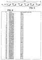
- the table in Figure 4 shows an example of portion 5 of compressed data that was the subject of analysis phase 23.
- This portion includes 40 images, identified on the board by a serial number included between 0 and 39, which is intended to facilitate reading.
- the first column contains this serial number.
- the second column contains the address in memory buffer 2 at the start of the data relating to the compressed image identified by the serial number of the first column.
- the third column contains the type image and the time stamp which indicates the serial number (for a display at nominal speed) in the GOP to which the image belongs considered.
- the images contained in the portion of stream 5 belong a number of GOP structure similar to that shown in Figure 3.
- the start of the images decodable is located at image number 2 of the list, which is image I1 of the first whole GOP.
- This intra-coded image makes it possible to decode some at minus the GOP images of which it is a part, from image 3 (B0) to the image No. 12 (P11).
- the images are presented here in the decoding order and not display order.
- the virtual time base is N images passed by VSYNC, which amounts to display one image every N images at each VSYNC event. If we note VSYNC (0) the vertical synchronization event corresponding to the display of image n ° 2 (image I1), it should be displayed, depending on the base of theoretical virtual time at the p-th synchronization event from VSYNC (0) denoted VSYNC (p), the (Nxp) -th image coming after I1 in order display, at nominal speed (x1).
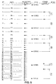
- FIG. 5 represents the images decoded from image No. 2 (picture I1), but in the display order in forward.
- the first column contains the sequence number associated with this image according to the first column from the table of figure 4.
- the second column indicates for each image the type and serial number in his GOP.
- the third column contains horizontal arrows which indicate time base events virtual: there are N events according to the virtual time base for a VSYNC (the time between two VSYNCs being constant for example 0.04 s).
- the fourth column contains horizontal arrows on the lines corresponding to the theoretical image displayed according to the theoretical speed V, at VSYNC.
- the fifth column contains horizontal arrows on the lines corresponding to the image actually displayed at each VSYNC.
- the sixth and last column contains vertical lines which give a representation of the delay at each event in the display time base, and the numbers in the circles indicate the delay in terms of number of images, as calculated below.
- the decoding is done in a step 25 (FIG. 2) so sequential across all images, in forward.
- the image to be displayed according to the theoretical speed xN is determined in a step 26 according to the virtual time base. It is image n ° 7 (B4), in the case where the theoretical speed adopted is for example equal to x3.
- the decoder after decoding the image I1, the decoder must perform, in this order, the decoding of image n ° 4 (P3) necessary to decode B2, then picture n ° 5 (B2), and picture n ° 6 (P5), before being able to decode B4.
- the image being decoded is image No. 5 (B2) and image No. 7 (B4) has not yet been decoded.
- the image which is decoded and available for display which comes before image n ° 7 (B4) in the display order at nominal speed, and which is closest to the image No. 7 (B4).
- the virtual time base represented in the third column of the table of figure 5, is based on a theoretical parameter three images passed by VSYNC, i.e. images n ° 5, 4 and 7 (respectively B2, P3 and B4).
- the image to display to VSYNC (1) should be, as indicated in the fourth column of the table Figure 5, image No. 7 (B4).
- the image actually displayed is identified by the arrow in the fifth column of the table, pointing to image n ° 4 (P3).
- a step 28 the delay of the display is then calculated by compared to the theoretical speed. It is equal in this case to an image (B4) and is shown in the sixth column of the table in Figure 5.
- the delay is compared to four thresholds N1, N2, N3 and N4, which in an example are respectively of an image, three images, four images and seven images.
- the delay is not strictly greater than the first threshold N1. This is why all images continue to be decoded and displayed, according to the rule b / indicated above.
- Decoding 25 continues.
- a new step 26 takes place in which the next image to be displayed is calculated according to the base theoretical time. This is the third image to display after image 7 (B4) or image n ° 8 (P7).
- the decoder has finished decoding of image n ° 5 (B2), then that of image n ° 6 (P5), and is during decoding of image n ° 7 (B4) from images n ° 4 and n ° 6, i.e. P3 and P5 respectively.
- image n ° 8 (P7) is not still available.
- the image to be displayed at the moment VSYNC (5) is image n ° 29 (B2).
- the decoding is continues on image n ° 14 (type I image), B images are not decoded and image n ° 16 (P3) as well as the P-type images predicted from P3, i.e. images n ° 18, 20, 22, 24 are not decoded.
- Image n ° 26 (I1), then image No. 28 (P3) is decoded.
- n ° 29 (B2) is not decoded. It is therefore image n ° 26 (I1) which is displayed because it is the decoded image available for display to be displayed in forward speed order nominal before image n ° 29 (B2) and which is closest to image n ° 25. The delay is one frame. All images will be decoded again. The decoding is done on images n ° 29, 30 and 31.
Landscapes
- Engineering & Computer Science (AREA)
- Multimedia (AREA)
- Signal Processing (AREA)
- Television Signal Processing For Recording (AREA)
- Compression Or Coding Systems Of Tv Signals (AREA)
- Signal Processing For Digital Recording And Reproducing (AREA)
Applications Claiming Priority (2)
| Application Number | Priority Date | Filing Date | Title |
|---|---|---|---|
| FR0216327 | 2002-12-20 | ||
| FR0216327A FR2849331A1 (fr) | 2002-12-20 | 2002-12-20 | Procede et dispositif de decodage et d'affichage en marche avant acceleree d'images mpeg, circuit pilote video et boitier decodeur incorporant un tel dispositif |
Publications (1)
| Publication Number | Publication Date |
|---|---|
| EP1432247A1 true EP1432247A1 (de) | 2004-06-23 |
Family
ID=32338982
Family Applications (1)
| Application Number | Title | Priority Date | Filing Date |
|---|---|---|---|
| EP03293015A Withdrawn EP1432247A1 (de) | 2002-12-20 | 2003-12-02 | Verfahren und Anlage zur Dekodierung und zur Schnellen-Vorlauf-Anzeige von MPEG Bildern, Videopilotschaltung und ein eine solche Anlage enthaltendes Dekodiergehäuse. |
Country Status (4)
| Country | Link |
|---|---|
| US (1) | US20040228408A1 (de) |
| EP (1) | EP1432247A1 (de) |
| JP (1) | JP2004208315A (de) |
| FR (1) | FR2849331A1 (de) |
Families Citing this family (3)
| Publication number | Priority date | Publication date | Assignee | Title |
|---|---|---|---|---|
| TWI444047B (zh) * | 2006-06-16 | 2014-07-01 | Via Tech Inc | 用於視訊解碼的去方塊效應濾波器、視訊解碼器與圖形處理單元 |
| US10277248B2 (en) * | 2015-07-07 | 2019-04-30 | Tidal Systems, Inc. | Compression engine with consistent throughput |
| EP3324388B1 (de) * | 2015-07-14 | 2022-05-11 | Samsung Electronics Co., Ltd. | Anzeigeansteuerungsschaltung, anzeigeansteuerungsverfahren und elektronische anzeige |
Citations (2)
| Publication number | Priority date | Publication date | Assignee | Title |
|---|---|---|---|---|
| US6334021B1 (en) | 1994-06-24 | 2001-12-25 | Mitsubishi Denki Kabushiki Kaisha | Specially formatted optical disk and method of playback |
| US20020061183A1 (en) | 2000-10-10 | 2002-05-23 | Macinnis Alexander G. | System and method for personal video recording |
Family Cites Families (8)
| Publication number | Priority date | Publication date | Assignee | Title |
|---|---|---|---|---|
| US5847765A (en) * | 1993-11-12 | 1998-12-08 | Nec Corporation | Moving picture decoding control system |
| US5754241A (en) * | 1994-11-18 | 1998-05-19 | Sanyo Electric Co., Ltd | Video decoder capable of controlling encoded video data |
| JP3824678B2 (ja) * | 1995-05-09 | 2006-09-20 | 株式会社ルネサステクノロジ | 画像復号表示装置 |
| US7058721B1 (en) * | 1995-07-14 | 2006-06-06 | Broadband Royalty Corporation | Dynamic quality adjustment based on changing streaming constraints |
| US5949948A (en) * | 1995-11-20 | 1999-09-07 | Imedia Corporation | Method and apparatus for implementing playback features for compressed video data |
| US6034731A (en) * | 1997-08-13 | 2000-03-07 | Sarnoff Corporation | MPEG frame processing method and apparatus |
| JP4230636B2 (ja) * | 2000-02-29 | 2009-02-25 | 株式会社東芝 | 動画像再生方法および動画像再生装置 |
| TW527832B (en) * | 2000-04-20 | 2003-04-11 | Matsushita Electric Ind Co Ltd | Video encoding apparatus that adjusts code amount by skipping encoding of image data |
-
2002
- 2002-12-20 FR FR0216327A patent/FR2849331A1/fr active Pending
-
2003
- 2003-12-02 EP EP03293015A patent/EP1432247A1/de not_active Withdrawn
- 2003-12-19 US US10/742,602 patent/US20040228408A1/en not_active Abandoned
- 2003-12-22 JP JP2003424721A patent/JP2004208315A/ja active Pending
Patent Citations (2)
| Publication number | Priority date | Publication date | Assignee | Title |
|---|---|---|---|---|
| US6334021B1 (en) | 1994-06-24 | 2001-12-25 | Mitsubishi Denki Kabushiki Kaisha | Specially formatted optical disk and method of playback |
| US20020061183A1 (en) | 2000-10-10 | 2002-05-23 | Macinnis Alexander G. | System and method for personal video recording |
Also Published As
| Publication number | Publication date |
|---|---|
| US20040228408A1 (en) | 2004-11-18 |
| JP2004208315A (ja) | 2004-07-22 |
| FR2849331A1 (fr) | 2004-06-25 |
Similar Documents
| Publication | Publication Date | Title |
|---|---|---|
| US9098172B2 (en) | Apparatus, systems and methods for a thumbnail-sized scene index of media content | |
| EP2164256B1 (de) | System für die Bereitstellung sichtbarer Nachrichten während der Trickmodus-Wiedergabe bei einem PVR | |
| EP1447983B1 (de) | Verfahren zum Aufnehmen verschlüsselter Daten, Speichermedium und Verfahren zur Wiedergabe solcher Daten | |
| US7720350B2 (en) | Methods and systems for controlling trick mode play speeds | |
| EP1439701A2 (de) | Ton- und Videodecodierungsverfahren und entsprechendes Gerät, Videotreiberschaltung | |
| EP2056603A2 (de) | Systeme und Verfahren zum Abspielen von Werbung | |
| EP1432246B1 (de) | Verfahren und Gerät zur Dekodierung und zur Rückwärtsanzeige von MPEG-Bildern, Pilotvideoschaltung und ein ein solches Gerät enthaltender Dekoder | |
| US8045802B2 (en) | End of program pattern detector | |
| US8340196B2 (en) | Video motion menu generation in a low memory environment | |
| EP1590959B1 (de) | Sicheres gerät, das auf anforderung zum verteilen, aufzeichnen und anzeigen audiovisueller arbeiten mit einem format des typs mpeg-2 ts verwendet wird | |
| EP1432247A1 (de) | Verfahren und Anlage zur Dekodierung und zur Schnellen-Vorlauf-Anzeige von MPEG Bildern, Videopilotschaltung und ein eine solche Anlage enthaltendes Dekodiergehäuse. | |
| US11706486B2 (en) | Systems and methods to prevent or reduce ad fatigue using user preferences | |
| EP3170296B1 (de) | Verfahren zum zugriff auf durch ein endgerät geschützten multimedia-inhalt | |
| JP2004304676A (ja) | ランキング計算方式及びシステム | |
| FR2834416A1 (fr) | Procede de diffusion de services audiovisuels, central de diffusion et support d'enregistrement, procede de visualisation d'emissions audiovisuelles et dispositif associes | |
| FR3041852A1 (fr) | Procede et dispositif d'enrichissement d'une fonction pause de la lecture d'une sequence d'images | |
| FR2868232A1 (fr) | Systeme d'affichage d'une sequence d'images animees |
Legal Events
| Date | Code | Title | Description |
|---|---|---|---|
| PUAI | Public reference made under article 153(3) epc to a published international application that has entered the european phase |
Free format text: ORIGINAL CODE: 0009012 |
|
| AK | Designated contracting states |
Kind code of ref document: A1 Designated state(s): AT BE BG CH CY CZ DE DK EE ES FI FR GB GR HU IE IT LI LU MC NL PT RO SE SI SK TR |
|
| AX | Request for extension of the european patent |
Extension state: AL LT LV MK |
|
| 17P | Request for examination filed |
Effective date: 20041214 |
|
| AKX | Designation fees paid |
Designated state(s): DE FR GB IT |
|
| 17Q | First examination report despatched |
Effective date: 20090728 |
|
| STAA | Information on the status of an ep patent application or granted ep patent |
Free format text: STATUS: THE APPLICATION IS DEEMED TO BE WITHDRAWN |
|
| 18D | Application deemed to be withdrawn |
Effective date: 20120703 |