EP1432240A1 - Image sensor positioning system and method - Google Patents
Image sensor positioning system and method Download PDFInfo
- Publication number
- EP1432240A1 EP1432240A1 EP03078835A EP03078835A EP1432240A1 EP 1432240 A1 EP1432240 A1 EP 1432240A1 EP 03078835 A EP03078835 A EP 03078835A EP 03078835 A EP03078835 A EP 03078835A EP 1432240 A1 EP1432240 A1 EP 1432240A1
- Authority
- EP
- European Patent Office
- Prior art keywords
- image sensor
- mounting
- adhesive
- lens mount
- mounting surface
- Prior art date
- Legal status (The legal status is an assumption and is not a legal conclusion. Google has not performed a legal analysis and makes no representation as to the accuracy of the status listed.)
- Withdrawn
Links
Images


Classifications
-
- H—ELECTRICITY
- H04—ELECTRIC COMMUNICATION TECHNIQUE
- H04N—PICTORIAL COMMUNICATION, e.g. TELEVISION
- H04N23/00—Cameras or camera modules comprising electronic image sensors; Control thereof
- H04N23/50—Constructional details
- H04N23/54—Mounting of pick-up tubes, electronic image sensors, deviation or focusing coils
Definitions
- the present invention relates generally to the field of image sensing devices and positioning thereof. More particularly, the present invention relates to positioning an image sensor within an assembly
- a typical image sensor assembly is constructed by sealing an integrated circuit die, which serves as an image sensing device, in a cavity of a chip carrier package, and covering the cavity with a cover glass to protect the image sensing device from contamination.
- image sensing devices include CCD image sensors and CMOS image sensors.
- the image sensor assembly can then mounted in an optical system.
- Japanese patent publication 2112280 (1990) suggests use of exact constraints to mechanically locate cut edges of an image sensing device to features machined in a metal plate that composes the base of the carrier package.
- U.S. Patent No. 5,861,654 ( Johnson ), commonly assigned and incorporated herein by reference, discloses an image sensor assembly comprising an image sensing device and a carrier package adapted for exact constraint to a set of features on the carrier package that are externally accessible to reference locators, wherein the carrier package supports the image sensing device in a location within the carrier package that is referenced to the set of features.
- An object of the present invention is to provide a system and method of positioning an image sensor.
- Another object of the present invention is to provide such a system and method of positioning of an image sensor relative to a lens mount assembly.
- a method of positioning an image sensor relative to a mounting body comprising a substantially planar mounting surface disposed substantially parallel to a lens mount reference surface.
- the method comprises the steps of: constraining the mounting body in a predetermined position; identifying a predetermined distance from the reference surface to define a mounting position, the predetermined distance being measured along an axis substantially perpendicular to the reference surface toward the mounting surface; applying an adhesive to the mounting surface; applying the image sensor to the adhesive such that the image sensor is positioned at the mounting position; and curing the adhesive to securely mount the image sensor to the mounting surface at the mounting position.
- a method of positioning an image sensor relative to a mounting body comprising a substantially planar mounting surface disposed substantially parallel to a lens mount reference surface.
- the method comprises the steps of: constraining the mounting body in a predetermined position; identifying a fiducial on the image sensor; identifying a locator disposed on the mounting surface; identifying a predetermined distance from the lens mount reference surface to define a mounting position, the predetermined distance being measured along an axis substantially perpendicular to the lens mount reference surface toward the mounting surface; applying an adhesive to the mounting surface; aligning the fiducial and the locator to define a planar orientation; applying the image sensor to the adhesive such that the image sensor is in the planar orientation and positioned at the mounting position; and curing the adhesive to securely mount the image sensor to the mounting surface at the planar orientation and mounting position.
- a method of generating an image sensor assembly comprises the steps of: providing a plate having a substantially planar mounting surface; constraining the plate in a fixture in a predetermined position; applying an adhesive to the mounting surface; identifying a fiducial on an image sensor; identifying a locator disposed on the mounting surface; identifying a predetermined distance from a reference surface to define a mounting position, the predetermined distance being measured along an axis substantially perpendicular to the reference surface toward the mounting surface; aligning the fiducial and the locator to define a planar orientation; applying the image sensor to the adhesive such that the image sensor is in the planar orientation and positioned at the mounting position; and curing the adhesive to securely mount the image sensor to the mounting surface at the planar orientation and mounting position.
- a system for positioning an image sensor relative to a lens mount assembly comprises: a fixture for constraining the lens mount assembly in a predetermined position, the lens mount assembly comprising a substantially planar mounting surface disposed substantially parallel to a lens mount reference surface; means for identifying a predetermined distance from the lens mount reference surface to define a mounting position, the predetermined distance being measured along an axis substantially perpendicular to the lens mount reference surface toward the mounting surface; means for applying an adhesive to the mounting surface; means for applying the image sensor to the adhesive such that the image sensor is positioned at the mounting position; and curing means for curing the adhesive to securely mount the image sensor to the mounting surface at the mounting position.
- the present invention provides a system and method of positioning an image sensor.
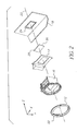
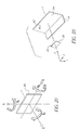
- FIG. 1 shows an exploded view of a lens mount assembly adapted to support a lens.
- FIG. 2 shows the lens mount assembly of FIG. 1 and an image sensor.
- FIG. 3 illustrates a cross-sectional view showing a positioning of an image sensor relative to a reference surface.
- FIG. 4 shows a mounting surface having adhesive disposed thereon in a pattern.
- FIG. 5 shows a flow diagram of a method of positioning an image sensor in a lens mount assembly in accordance with the present invention.
- FIG. 6 shows a rear body of a camera spaced from a fixture.
- FIG. 7 shows the rear body of FIG. 6 disposed within the fixture.
- FIG. 8 shows an image sensor being transported to the fixture.
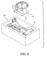
- FIG. 9 shows assembly of the lens mirror assembly to the mounting body.
- FIG. 10 shows a camera body of a camera spaced from a fixture.
- FIG. 11 shows a reference surface
- FIG. 12 shows an image sensor being transported to the fixture.
- FIG. 13 shows the camera body of FIG. 10 being removed from the fixture.
- FIG. 14 shows the mirror box assembly being mounted to the mounting body.
- FIG. 15 shows a camera body mounted to the mirror box assembly.
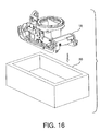
- FIG. 16 shows the camera body of FIG. 15 being disposed within a fixture.
- FIG. 17 shows a reference surface
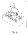
- FIG. 18 shows an image sensor being transported to the fixture.
- FIG. 19 shows the camera body being removed from the fixture.
- FIG. 20 shows the six degrees of freedom for the image sensor.
- FIG. 21 shows a flow diagram of a second method of positioning an image sensor in a lens mount assembly in accordance with the present invention.
- FIG. 22 shows a partial view of a wirebonded sensor.
- FIG. 23 shows a fiducial on the image sensor and a locator on the mounting surface, which are used to align the image sensor with the mounting surface.
- FIGS. 24a-24c show, respectively, a front, side, and top view of an image sensor package/assembly.
- FIG. 25 shows the positioning of the image sensor package/assembly of FIGS. 24a-24c in a camera body.
- FIG. 26 shows a flow diagram of a method of generating the image sensor package/assembly of FIGS. 24a-24c for positioning in the camera body of FIG. 25.
- FIG. 1 illustrates an exploded view of a lens mount assembly 10.
- Lens mount assembly 10 comprises a lens mount 12 adapted to receive a lens 14.
- Lens mount assembly further comprises a lens mount support 16 affixed to a mounting body 18, and a shutter 17.
- Mounting body 18 is, for example, a camera body or a rear body of a camera.
- the assembly of lens mount 12 and lens mount support 16 is hereinafter referred to as mirror box assembly 19.
- An axis 20 of lens mount assembly 10 is substantially perpendicular to a lens mount reference surface 22 disposed on a surface of lens mount 12. As illustrated in Figure 1, axis 20 is directed along the z-axis of the coordinate system shown.
- mounting body 18 comprises a substantially planar mounting surface 24 for supporting an image sensor 26 thereon.
- Mounting surface 24 is substantially parallel to reference surface 22, and therefore, substantially perpendicular to axis 20.
- image sensor 26 is mounted to mounting surface 24 by means of an adhesive 28 such that one surface 25 of image sensor 26 is disposed at a predetermined distance D from a reference surface.
- the reference surface is lens mount reference surface 22 of lens mount 12, as shown in Figure 3. Therefore, for ease of discussion only, the method of the present invention will be disclosed with reference to the reference surface being lens mount reference surface 22, though those skilled in the art will recognize that other reference surfaces can be employed.
- predetermined distance D from lens mount reference surface 22 is identified to define a mounting position for image sensor 26.
- Predetermined distance D is measured along axis 20 toward mounting surface 24, wherein axis 20 is substantially perpendicular to lens mount reference surface 22.
- predetermined distance D can relate to the optical lens design for the unit in which image sensor 26 is to be mounted. For example, if image sensor is to be mounted in a SLR camera, distance D is defined by the best focus distance of the camera platform. For one application of the present invention, distance D is in the range of 45-50mm.
- Adhesive 28 is applied to mounting surface 24 of mounting body 18, after which, image sensor 26 is applied to the adhesive such that image sensor 26 contacts the adhesive and is positioned at predetermined distance D along axis 20. The adhesive is cured wherein image sensor 26 is securely mounted to mounting surface 24 at predetermined distance D.
- Adhesive 28 can be applied by an automated adhesive dispensing device so as to dispense a consistent amount of adhesive. Such an adhesive dispensing process employs pressure and time to control the deposition of adhesive 28 on mounting surface 24. It is noted that sufficient adhesive 28 must be applied to mounting surface 24 to ensure that image sensor 26 is securely mounted to mounting surface 24. If insufficient adhesive 28 is applied, image sensor 26 may not be securely mounted. Preferably, adhesive 28 is dispensed such that adhesive 28 adheres to at least a portion of at least one side edge 31 of image sensor 26. Preferably, sufficient adhesive 28 is provided so as to contact from about 25 percent to about 50 percent of at least one of the image sensor's edge 31, as best shown in Figure 3.
- Adhesive 28 can be dispensed onto mounting surface 24 in a particular pattern so as to promote uniform contact of the adhesive between image sensor 26 and mounting surface 24 when image sensor 26 is applied to mounting surface 24.
- adhesive 28 can be dispensed on mounting surface 24 in a radiating pattern so as to promote flow of the adhesive toward side edges 31 of image sensor 26.
- adhesive 28 examples include a silver filled conductive epoxy, preferably Ablestik 967-1. Other suitable adhesives may be known to those skilled in the art. Note that image sensor 26 essentially floats on adhesive 28, and so can be positioned at the best focus distance. Accordingly, it is critical to select an adhesive that exhibits minimal shrinkage and expansion as the adhesive cures.
- electrical contacts to image sensor 26 are provided, for example by means of wirebonding, to the camera electronics (not shown).
- Figure 5 provides a flow diagram of a method for positioning image sensor 26 on mounting body 18 as illustrated in Figure 3.
- mounting body 18 is constrained in a predetermined position by methods more particularly described below.
- Predetermined distance D from lens mount reference surface 22 is identified at step 102 to define a mounting position.
- Predetermined distance D is measured along axis 20 toward mounting surface 24, wherein axis 20 is substantially perpendicular to lens mount reference surface 22 adhesive 28 is applied to mounting surface 24 (step 104).
- Image sensor 26 is then applied to the adhesive (step 106), by means more particularly described below, such that image sensor 26 contacts the adhesive and is positioned at a mounting position which is at predetermined distance D along axis 20.
- the adhesive is cured (step 108) wherein image sensor 26 is securely mounted to mounting surface 24 at the mounting position.
- adhesive 28 secures image sensor 26 so as to rigidly mount image sensor 26 to mounting surface 24 at predetermined distance D.
- the method of Figure 5 can be practiced to adhere image sensor 26 within lens mount assembly 10, or alternatively, mirror box assembly 19 might be mounted to mounting body 18 after image sensor 26 is adhered to mounting body 18 having been positioned relative to a reference datum.
- a transparent cover is applied to image sensor 26 subsequent to the step of curing the adhesive and wirebonding.
- FIG. 5 The method of Figure 5 can be practiced wherein image sensor 26 is mounted directly to mounting body 18 prior to mirror box assembly 19 being mounted to mounting body 18. That is, mirror box assembly 19 is mounted to mounting body 18 after image sensor 26 is adhered to mounting body 18. Image sensor 26 is to be applied to mounting surface 24 disposed on a side of mounting body 18 directed toward lens mount 12.
- mounting body 18 is constrained in a mounting fixture 30 to provide a predetermined position. Fixture 30 is shown in Figure 6 as an auer boat, though those skilled in the art will recognize that other mounting fixtures can be employed.
- a mounting body 18 is a rear body of a camera. Therefore, for illustrative purposes only, mounting body 18 is shown in Figures 6-9 as a rear body of a camera. Mounting body 18 can be positioned by means of pins/slots or side-to-side x, y datum features.
- Mounting body 18 can be positioned within mounting fixture 30 by several methods known to those skilled in the art.
- mounting body 18 can include a substantially planar surface on a side opposite mounting surface 24, shown in Figure 6 as constrained mounting body surface 32, which is supported by a substantially planar fixture surface 34.
- fixture 30 can include a feature to mate with a particular feature of mounting body 18 to constrain mounting body 18. Then, a feature on either fixture 30 or mounting body 18 is employed as a reference x, y, z datum plane for locating of image sensor 26, and thereafter, mirror box assembly 19. That is, reference datum locations 36a-36c are employed so as to locate image sensor 26 at predetermined distance D.
- Figure 7 shows three reference datum locations 36a-36c. This positioning of mounting body 18 within fixture 30 provides for exact constraint of mounting body 18.
- Image sensor 26 With mounting body 18 positioned within fixture 30, a predetermined amount of adhesive 28 is then applied to mounting surface 24. Image sensor 26 is then brought into position for mounting to mounting surface 24. Image sensor 26 can be brought into position by means known to those skilled in the art, including, but not limited to, a manual operation, a pick-and-place mechanism, or the like.
- Such a pick-and-place mechanism can "pick" up image sensor 26 from a location proximate fixture 30 and "place" image sensor 26 at the mounting position.
- the pick-and-place mechanism can include a vision-enabled device to locate a reference datum location or allow fiducial recognition.
- An example of a suitable vision enabled device is a CCD camera or the like. It is recognized that while the vision-enabled device can augment the pick-and-place mechanism, the vision-enabled device can be separate from the pick-and-place mechanism.
- Reference datum locations from either mounting body 18 or fixture 30 are determined for proper positioning of image sensor 26.
- a pick-and-place mechanism 38 can locate reference datum locations 36a, 36b, 36c on mounting body 18.
- Image sensor 26 is mounted to adhesive 28, and adhesive 28 is then cured.
- mirror box assembly 19 and shutter 17 can then be mounted to mounting body 18 by means known to those skilled in the art, as shown in Figure 9, whereby image sensor 26 is disposed at predetermined, distance D from reference surface 22.
- FIG. 10-14 the method of Figure 5 is practiced wherein the reference datums are referenced from reference surface 22.
- mounting body 18 is constrained in fixture 30 to provide a predetermined position.
- fixture 30 is shown in Figures 10-14 as an auer boat, though those skilled in the art will recognize that other mounting fixtures can be employed.
- one example of a mounting body 18 is a camera body. Therefore, for illustrative purposes only, mounting body 18 is shown in Figures 10-14 as a camera body. Once positioned within fixture 30, adhesive 28 is applied to mounting surface 24.
- a pick-and-place mechanism locates reference datums x, y, z in space which correspond with the location of reference surface 22 (reference surface 22 being shown in the figures to illustrate that the datums are referenced from this surface). Then, pick-and-place mechanism 38 is used to properly apply image sensor 26 to the adhesive disposed on mounting surface 24 whereby image sensor 26 is disposed at predetermined distance D from reference surface 22. Once cured, mounting body 18 is removed from fixture 30 ( Figure 13) so that mirror box assembly 19 and shutter 17 (not shown) can be assembled to mounting body 18 ( Figure 14).
- the method of Figure 5 is practiced wherein the reference datums are referenced from reference surface 22, wherein reference surface 22 is affixed to mounting body 18. That is, since image sensor 26 is smaller than an opening in lens mount 12 and lens mount support 16, image sensor 26 can be mounted to mounting body 18 when mirror box assembly 19 is mounted mounting body 18.
- mounting body 18 is constrained in fixture 30 to provide a predetermined position.
- fixture 30 is shown in Figures 15-19 as an auer boat, though those skilled in the art will recognize that other mounting fixtures can be employed.
- a mounting body 18 is a camera body. Therefore, for illustrative purposes only, mounting body 18 is shown in Figures 15-19 as a camera body.
- pick-and-place mechanism 38 locates reference surface 22 and determines datums x, y, z on reference surface 22. Then, pick-and-place mechanism 38 is used to properly apply image sensor 26 to the adhesive disposed on mounting surface 24 whereby image sensor 26 is disposed at predetermined distance D from reference surface 22 ( Figure 18). Once cured, mounting body 18 is removed from fixture 30 ( Figure 19).
- exactly constraining an element involves specifying the minimum number of forces needed to exactly locate the element in a set of spatial coordinates.
- degrees of freedom for placement of image sensor 26. These degrees of freedom are x, y, z, ⁇ x, ⁇ y, and ⁇ z.
- the ⁇ x, ⁇ y, and z degree of freedom is controlled by mounting image sensor 26 at the predetermined mounting position. Control of x and y is obtained by referencing from the center of lens mount 12. Control of ⁇ z can be obtained by employing a fiducial on image sensor 26 and aligning the fiducial with a locator disposed on the mounting surface.
- the present invention provides an automated precision alignment method using a pick-and-place machine augmented with an optical vision system.
- Figure 21 shows a flow diagram of a second method of positioning an image sensor in a lens mount assembly in accordance with the present invention wherein a fiducial and a locator are employed.
- mounting body 18 is constrained in a predetermined position.
- constraint of mounting body 18 can be accomplished, for example, by positioning lens mount assembly in fixture 30 in order to exactly constrain mounting body 18 relative to the fixture.
- a fiducial is identified on image sensor 26 (step 202).
- a locator disposed on mounting surface 24 is identified (step 204).
- Predetermined distance D from lens mount reference surface 22, referenced from the center of lens mount 12, is identified at step 206 to define a mounting position and obtain exact x, y, z positioning.
- Adhesive 28 is applied to mounting surface 24 (step 208).
- the fiducial and the locator are aligned to define a planar orientation (step 210).
- the planar orientation will define the x, y plane for the placement of image sensor 26.
- Image sensor 26 is applied to adhesive 28 (step 212) such that image sensor 26 contacts the adhesive and is in the planar orientation and positioned at a mounting position which is at predetermined distance D along axis 20.
- the adhesive is cured (step 214) wherein image sensor 26 is securely mounted to mounting surface 24 at the mounting position. Once cured, the remaining image sensor package/assembly is completed through the wirebonding and functional test.
- Figure 22 shows a partial view of a wirebonded image sensor 26.
- Figure 23 illustrates a fiducial 40 disposed on image sensor 26.
- fiducial 40 is shown as a cross-hatch, though those skilled in the art will recognize that other markings may be employed, for example, a line, a point, asterisk, or triangle.
- a locator 42 is shown on mounting support 18. As illustrated, locator 42 is shown as an asterisk, though those skilled in the art will recognize that other markings may be employed, for example, a line, a point, cross-hatch, or triangle.
- Fiducial 40 and locator 42 are aligned to define a planar orientation at step 210. As is shown by the coordinate system in Figure 23, the alignment of fiducial 40 with locator 42 defines a plane in which to orient image sensor 26 relative to mounting surface 24. Therefore, this planar orientation defines the x,y plane for the placement of image sensor 26 relative to mounting surface 24.
- Fixture 30 can be configured to constrain mounting body 18 for proper alignment of fiducial 40 and locator 42, as described above with reference to the first, second, and third embodiments.
- the means/method of applying image sensor 26 could reference from reference surface 22 and place image sensor 26 to provide precise x,y, and z positioning.
- the assembly of the optical system can be completed.
- a glass cover over image sensor 26 to protect image sensor 26 from contamination.
- Methods known to those skilled in the art can be employed to place the glass cover, for example, a pick-and-place mechanism, optical placement device, or the like.
- alignment and calibration of the image sensor within the lens mounting assembly is accomplished by the placement of the image sensor by the means/method employed to position the image sensor.
- Predetermined placement specifications are preferably defined to ensure precision placement of the image sensor. For example, a maximum skew angle would be defined as well as tolerances for focus, tilt, and x/y dimensions.
- an image sensor has been positioned within the specifications of within +/- 0.001 inch focus and tilt (Z+ ⁇ x+ ⁇ y), 2 degree maximum skew ( ⁇ z), and +/-0.003 inch x and y.
- the method of the present invention employs exact constraint modeling to provide precision placement of the image sensor relative to the lens mount assembly. Placement of the image sensor directly relative to the mounting body eliminates/reduces tolerance stackups, thereby reducing manufacturing costs and time, and promoting servicability. As such, lens mount assembly 10 is focused without active alignment techniques or post-machining processes.
- the method of the present invention can be employed with different lens mount assemblies and image sensors.
- image sensor 26 is mounted to a plate, and the plate is positioned on mounting body 18. That is, image sensor 26 is precision placed (using constraint modeling) to a plate, and the plate can be directly mounted within a camera body. Positioning the image sensor directly on the plate eliminates tolerance stackups, thereby allowing the image sensor to be placed in the camera without any other active alignment process or techniques.
- a plate 50 is provided (step 300).
- Plate 50 has a substantially planar surface to receive image sensor 26, as best shown in Figures 24b and 24c.
- Plate 50 also includes features for mating with placement features on mounting body 18. These features are shown in Figure 24a as mounting holes 52. (It is noted that while four features, i.e., mounting holes 52 are shown, three features can be employed. For some applications, five features may be established.)
- Plate 50 is positioned in fixture 30 to constrain plate 50 in a predetermined position (step 302). As with the embodiments described above, fixture 30 can include pins/slots to locate plate 50 in an x,y predetermined position.
- Adhesive 28 is applied to the mounting surface (step 304). As with embodiment three described above, fiducials are identified on image sensor 26 (step 306). Similarly, a locator disposed on the mounting surface of plate 50 is identified (step 308). These fiducials and locators are located by the pick-and-place mechanism or the like, and aligned to define a planar orientation (step 312). Pick-and-place mechanism 38 transfers image sensor 26 to the mounting surface. Preferably, pick-and-place mechanism contacts plate 50 by means of features 52 so as to place image sensor 26 with the predetermined specifications (step 314). That is, image sensor 26 is applied to adhesive 28 such that the image sensor is in the planar orientation and positioned at the mounting position.
- image sensor assembly 48 is positioned within a camera body 60 utilizing the same x,y, and z reference locations, as best shown in Figure 25.
Landscapes
- Engineering & Computer Science (AREA)
- Multimedia (AREA)
- Signal Processing (AREA)
- Transforming Light Signals Into Electric Signals (AREA)
- Solid State Image Pick-Up Elements (AREA)
- Camera Bodies And Camera Details Or Accessories (AREA)
- Studio Devices (AREA)
Abstract
A method of positioning an image sensor relative to a mounting
body wherein the lens mount assembly comprises a substantially planar mounting
surface disposed substantially parallel to a lens mount reference surface. The
method comprises the steps of: constraining the mounting body in a predetermined
position; identifying a predetermined distance from the lens mount reference
surface to define a mounting position, the predetermined distance being measured
along an axis substantially perpendicular to the lens mount reference surface
toward the mounting surface; applying an adhesive to the mounting surface;
applying the image sensor to the adhesive such that the image sensor is positioned
at the mounting position; and curing the adhesive to securely mount the image
sensor to the mounting surface at the mounting position.
Description
- The present invention relates generally to the field of image sensing devices and positioning thereof. More particularly, the present invention relates to positioning an image sensor within an assembly
- A typical image sensor assembly is constructed by sealing an integrated circuit die, which serves as an image sensing device, in a cavity of a chip carrier package, and covering the cavity with a cover glass to protect the image sensing device from contamination. Examples of image sensing devices include CCD image sensors and CMOS image sensors. The image sensor assembly can then mounted in an optical system.
- Precise positioning of the image sensor and/or image sensor assembly is needed to provide an optimum focus position for an optical system. Accordingly, methods have been disclosed to assemble or position an image sensor or image sensor assembly.
- Japanese patent publication 2112280 (1990) suggests use of exact constraints to mechanically locate cut edges of an image sensing device to features machined in a metal plate that composes the base of the carrier package.
- U.S. Patent No. 5,861,654 (Johnson), commonly assigned and incorporated herein by reference, discloses an image sensor assembly comprising an image sensing device and a carrier package adapted for exact constraint to a set of features on the carrier package that are externally accessible to reference locators, wherein the carrier package supports the image sensing device in a location within the carrier package that is referenced to the set of features.
- While such apparatus or methods may have achieved certain degrees of success in their particular applications, a need continues to exist to simplify the positioning of an image sensor, particularly relative to a lens mount assembly or a reference surface.
- An object of the present invention is to provide a system and method of positioning an image sensor.
- Another object of the present invention is to provide such a system and method of positioning of an image sensor relative to a lens mount assembly.
- These objects are given only by way of illustrative example, and such objects may be exemplary of one or more embodiments of the invention. Other desirable objectives and advantages inherently achieved by the disclosed invention may occur or become apparent to those skilled in the art. The invention is defined by the appended claims.
- According to one aspect of the invention, there is provided a method of positioning an image sensor relative to a mounting body comprising a substantially planar mounting surface disposed substantially parallel to a lens mount reference surface. The method comprises the steps of: constraining the mounting body in a predetermined position; identifying a predetermined distance from the reference surface to define a mounting position, the predetermined distance being measured along an axis substantially perpendicular to the reference surface toward the mounting surface; applying an adhesive to the mounting surface; applying the image sensor to the adhesive such that the image sensor is positioned at the mounting position; and curing the adhesive to securely mount the image sensor to the mounting surface at the mounting position.
- According to another aspect of the invention, there is provided a method of positioning an image sensor relative to a mounting body comprising a substantially planar mounting surface disposed substantially parallel to a lens mount reference surface. The method comprises the steps of: constraining the mounting body in a predetermined position; identifying a fiducial on the image sensor; identifying a locator disposed on the mounting surface; identifying a predetermined distance from the lens mount reference surface to define a mounting position, the predetermined distance being measured along an axis substantially perpendicular to the lens mount reference surface toward the mounting surface; applying an adhesive to the mounting surface; aligning the fiducial and the locator to define a planar orientation; applying the image sensor to the adhesive such that the image sensor is in the planar orientation and positioned at the mounting position; and curing the adhesive to securely mount the image sensor to the mounting surface at the planar orientation and mounting position.
- According to a further aspect of the invention, there is provided a method of generating an image sensor assembly. The method comprises the steps of: providing a plate having a substantially planar mounting surface; constraining the plate in a fixture in a predetermined position; applying an adhesive to the mounting surface; identifying a fiducial on an image sensor; identifying a locator disposed on the mounting surface; identifying a predetermined distance from a reference surface to define a mounting position, the predetermined distance being measured along an axis substantially perpendicular to the reference surface toward the mounting surface; aligning the fiducial and the locator to define a planar orientation; applying the image sensor to the adhesive such that the image sensor is in the planar orientation and positioned at the mounting position; and curing the adhesive to securely mount the image sensor to the mounting surface at the planar orientation and mounting position.
- According to a still further aspect of the invention, there is provided a system for positioning an image sensor relative to a lens mount assembly. The system comprises: a fixture for constraining the lens mount assembly in a predetermined position, the lens mount assembly comprising a substantially planar mounting surface disposed substantially parallel to a lens mount reference surface; means for identifying a predetermined distance from the lens mount reference surface to define a mounting position, the predetermined distance being measured along an axis substantially perpendicular to the lens mount reference surface toward the mounting surface; means for applying an adhesive to the mounting surface; means for applying the image sensor to the adhesive such that the image sensor is positioned at the mounting position; and curing means for curing the adhesive to securely mount the image sensor to the mounting surface at the mounting position.
- The present invention provides a system and method of positioning an image sensor.
- The foregoing and other objects, features, and advantages of the invention will be apparent from the following more particular description of the preferred embodiments of the invention, as illustrated in the accompanying drawings.
- FIG. 1 shows an exploded view of a lens mount assembly adapted to support a lens.
- FIG. 2 shows the lens mount assembly of FIG. 1 and an image sensor.
- FIG. 3 illustrates a cross-sectional view showing a positioning of an image sensor relative to a reference surface.
- FIG. 4 shows a mounting surface having adhesive disposed thereon in a pattern.
- FIG. 5 shows a flow diagram of a method of positioning an image sensor in a lens mount assembly in accordance with the present invention.
- FIG. 6 shows a rear body of a camera spaced from a fixture.
- FIG. 7 shows the rear body of FIG. 6 disposed within the fixture.
- FIG. 8 shows an image sensor being transported to the fixture.
- FIG. 9 shows assembly of the lens mirror assembly to the mounting body.
- FIG. 10 shows a camera body of a camera spaced from a fixture.
- FIG. 11 shows a reference surface.
- FIG. 12 shows an image sensor being transported to the fixture.
- FIG. 13 shows the camera body of FIG. 10 being removed from the fixture.
- FIG. 14 shows the mirror box assembly being mounted to the mounting body.
- FIG. 15 shows a camera body mounted to the mirror box assembly.
- FIG. 16 shows the camera body of FIG. 15 being disposed within a fixture.
- FIG. 17 shows a reference surface.
- FIG. 18 shows an image sensor being transported to the fixture.
- FIG. 19 shows the camera body being removed from the fixture.
- FIG. 20 shows the six degrees of freedom for the image sensor.
- FIG. 21 shows a flow diagram of a second method of positioning an image sensor in a lens mount assembly in accordance with the present invention.
- FIG. 22 shows a partial view of a wirebonded sensor.
- FIG. 23 shows a fiducial on the image sensor and a locator on the mounting surface, which are used to align the image sensor with the mounting surface.
- FIGS. 24a-24c show, respectively, a front, side, and top view of an image sensor package/assembly.
- FIG. 25 shows the positioning of the image sensor package/assembly of FIGS. 24a-24c in a camera body.
- FIG. 26 shows a flow diagram of a method of generating the image sensor package/assembly of FIGS. 24a-24c for positioning in the camera body of FIG. 25.
- The following is a detailed description of the preferred embodiments of the invention, reference being made to the drawings in which the same reference numerals identify the same elements of structure in each of the several figures.
- Figure 1 illustrates an exploded view of a
lens mount assembly 10.Lens mount assembly 10 comprises alens mount 12 adapted to receive alens 14. Lens mount assembly further comprises alens mount support 16 affixed to amounting body 18, and ashutter 17.Mounting body 18 is, for example, a camera body or a rear body of a camera. The assembly oflens mount 12 andlens mount support 16 is hereinafter referred to asmirror box assembly 19. - An
axis 20 oflens mount assembly 10 is substantially perpendicular to a lensmount reference surface 22 disposed on a surface oflens mount 12. As illustrated in Figure 1,axis 20 is directed along the z-axis of the coordinate system shown. - Referring now to Figure 2,
mounting body 18 comprises a substantiallyplanar mounting surface 24 for supporting animage sensor 26 thereon.Mounting surface 24 is substantially parallel toreference surface 22, and therefore, substantially perpendicular toaxis 20. - Referring to Figure 3,
image sensor 26 is mounted to mountingsurface 24 by means of an adhesive 28 such that onesurface 25 ofimage sensor 26 is disposed at a predetermined distance D from a reference surface. In a preferred embodiment, the reference surface is lensmount reference surface 22 oflens mount 12, as shown in Figure 3. Therefore, for ease of discussion only, the method of the present invention will be disclosed with reference to the reference surface being lens mountreference surface 22, though those skilled in the art will recognize that other reference surfaces can be employed. - Still referring to Figure 3, predetermined distance D from lens mount
reference surface 22 is identified to define a mounting position forimage sensor 26. Predetermined distance D is measured alongaxis 20 toward mountingsurface 24, whereinaxis 20 is substantially perpendicular to lens mountreference surface 22. As will become apparent, predetermined distance D can relate to the optical lens design for the unit in whichimage sensor 26 is to be mounted. For example, if image sensor is to be mounted in a SLR camera, distance D is defined by the best focus distance of the camera platform. For one application of the present invention, distance D is in the range of 45-50mm. -
Adhesive 28 is applied to mountingsurface 24 of mountingbody 18, after which,image sensor 26 is applied to the adhesive such thatimage sensor 26 contacts the adhesive and is positioned at predetermined distance D alongaxis 20. The adhesive is cured whereinimage sensor 26 is securely mounted to mountingsurface 24 at predetermined distance D. -
Adhesive 28 can be applied by an automated adhesive dispensing device so as to dispense a consistent amount of adhesive. Such an adhesive dispensing process employs pressure and time to control the deposition of adhesive 28 on mountingsurface 24. It is noted that sufficient adhesive 28 must be applied to mountingsurface 24 to ensure thatimage sensor 26 is securely mounted to mountingsurface 24. Ifinsufficient adhesive 28 is applied,image sensor 26 may not be securely mounted. Preferably, adhesive 28 is dispensed such that adhesive 28 adheres to at least a portion of at least oneside edge 31 ofimage sensor 26. Preferably,sufficient adhesive 28 is provided so as to contact from about 25 percent to about 50 percent of at least one of the image sensor'sedge 31, as best shown in Figure 3. -
Adhesive 28 can be dispensed onto mountingsurface 24 in a particular pattern so as to promote uniform contact of the adhesive betweenimage sensor 26 and mountingsurface 24 whenimage sensor 26 is applied to mountingsurface 24. For example, referring to Figure 4, adhesive 28 can be dispensed on mountingsurface 24 in a radiating pattern so as to promote flow of the adhesive toward side edges 31 ofimage sensor 26. - Examples of adhesive 28 include a silver filled conductive epoxy, preferably Ablestik 967-1. Other suitable adhesives may be known to those skilled in the art. Note that
image sensor 26 essentially floats on adhesive 28, and so can be positioned at the best focus distance. Accordingly, it is critical to select an adhesive that exhibits minimal shrinkage and expansion as the adhesive cures. - After adhesive 28 is cured, electrical contacts to image
sensor 26 are provided, for example by means of wirebonding, to the camera electronics (not shown). - Figure 5 provides a flow diagram of a method for positioning
image sensor 26 on mountingbody 18 as illustrated in Figure 3. Atstep 100, mountingbody 18 is constrained in a predetermined position by methods more particularly described below. Predetermined distance D from lens mountreference surface 22 is identified atstep 102 to define a mounting position. Predetermined distance D is measured alongaxis 20 toward mountingsurface 24, whereinaxis 20 is substantially perpendicular to lens mountreference surface 22 adhesive 28 is applied to mounting surface 24 (step 104).Image sensor 26 is then applied to the adhesive (step 106), by means more particularly described below, such thatimage sensor 26 contacts the adhesive and is positioned at a mounting position which is at predetermined distance D alongaxis 20. The adhesive is cured (step 108) whereinimage sensor 26 is securely mounted to mountingsurface 24 at the mounting position. As such, adhesive 28 securesimage sensor 26 so as to rigidly mountimage sensor 26 to mountingsurface 24 at predetermined distance D. As will be more particularly described below, the method of Figure 5 can be practiced to adhereimage sensor 26 withinlens mount assembly 10, or alternatively,mirror box assembly 19 might be mounted to mountingbody 18 afterimage sensor 26 is adhered to mountingbody 18 having been positioned relative to a reference datum. - To further protect the image sensor, a transparent cover is applied to image
sensor 26 subsequent to the step of curing the adhesive and wirebonding. - First Embodiment. The method of Figure 5 can be practiced wherein
image sensor 26 is mounted directly to mountingbody 18 prior tomirror box assembly 19 being mounted to mountingbody 18. That is,mirror box assembly 19 is mounted to mountingbody 18 afterimage sensor 26 is adhered to mountingbody 18.Image sensor 26 is to be applied to mountingsurface 24 disposed on a side of mountingbody 18 directed towardlens mount 12. Referring to Figures 6-9, mountingbody 18 is constrained in a mountingfixture 30 to provide a predetermined position.Fixture 30 is shown in Figure 6 as an auer boat, though those skilled in the art will recognize that other mounting fixtures can be employed. As indicated above, one example of a mountingbody 18 is a rear body of a camera. Therefore, for illustrative purposes only, mountingbody 18 is shown in Figures 6-9 as a rear body of a camera. Mountingbody 18 can be positioned by means of pins/slots or side-to-side x, y datum features. - Mounting
body 18 can be positioned within mountingfixture 30 by several methods known to those skilled in the art. For example, mountingbody 18 can include a substantially planar surface on a side opposite mountingsurface 24, shown in Figure 6 as constrained mountingbody surface 32, which is supported by a substantiallyplanar fixture surface 34. Alternatively,fixture 30 can include a feature to mate with a particular feature of mountingbody 18 to constrain mountingbody 18. Then, a feature on eitherfixture 30 or mountingbody 18 is employed as a reference x, y, z datum plane for locating ofimage sensor 26, and thereafter,mirror box assembly 19. That is, reference datum locations 36a-36c are employed so as to locateimage sensor 26 at predetermined distance D. Figure 7 shows three reference datum locations 36a-36c. This positioning of mountingbody 18 withinfixture 30 provides for exact constraint of mountingbody 18. - With mounting
body 18 positioned withinfixture 30, a predetermined amount of adhesive 28 is then applied to mountingsurface 24.Image sensor 26 is then brought into position for mounting to mountingsurface 24.Image sensor 26 can be brought into position by means known to those skilled in the art, including, but not limited to, a manual operation, a pick-and-place mechanism, or the like. - Such a pick-and-place mechanism can "pick" up
image sensor 26 from a locationproximate fixture 30 and "place"image sensor 26 at the mounting position. The pick-and-place mechanism can include a vision-enabled device to locate a reference datum location or allow fiducial recognition. An example of a suitable vision enabled device is a CCD camera or the like. It is recognized that while the vision-enabled device can augment the pick-and-place mechanism, the vision-enabled device can be separate from the pick-and-place mechanism. - Reference datum locations from either mounting
body 18 orfixture 30 are determined for proper positioning ofimage sensor 26. For example, referring to Figure 8, a pick-and-place mechanism 38 can locate reference datum locations 36a, 36b, 36c on mountingbody 18.Image sensor 26 is mounted to adhesive 28, and adhesive 28 is then cured. Once cured,mirror box assembly 19 and shutter 17 (not shown) can then be mounted to mountingbody 18 by means known to those skilled in the art, as shown in Figure 9, wherebyimage sensor 26 is disposed at predetermined, distance D fromreference surface 22. - Second Embodiment. In a second embodiment, the method of Figure 5 is practiced wherein the reference datums are referenced from
reference surface 22. Referring to Figures 10-14, mountingbody 18 is constrained infixture 30 to provide a predetermined position. Again,fixture 30 is shown in Figures 10-14 as an auer boat, though those skilled in the art will recognize that other mounting fixtures can be employed. As indicated above, one example of a mountingbody 18 is a camera body. Therefore, for illustrative purposes only, mountingbody 18 is shown in Figures 10-14 as a camera body. Once positioned withinfixture 30, adhesive 28 is applied to mountingsurface 24. - Referring now to Figure 11, a pick-and-place mechanism, or the like, locates reference datums x, y, z in space which correspond with the location of reference surface 22 (
reference surface 22 being shown in the figures to illustrate that the datums are referenced from this surface). Then, pick-and-place mechanism 38 is used to properly applyimage sensor 26 to the adhesive disposed on mountingsurface 24 wherebyimage sensor 26 is disposed at predetermined distance D fromreference surface 22. Once cured, mountingbody 18 is removed from fixture 30 (Figure 13) so thatmirror box assembly 19 and shutter 17 (not shown) can be assembled to mounting body 18 (Figure 14). - Third Embodiment. In a third embodiment, the method of Figure 5 is practiced wherein the reference datums are referenced from
reference surface 22, whereinreference surface 22 is affixed to mountingbody 18. That is, sinceimage sensor 26 is smaller than an opening inlens mount 12 and lens mountsupport 16,image sensor 26 can be mounted to mountingbody 18 whenmirror box assembly 19 is mounted mountingbody 18. - Referring to Figures 15-19, with
mirror box assembly 19 mounted to mountingbody 18, mountingbody 18 is constrained infixture 30 to provide a predetermined position. Again,fixture 30 is shown in Figures 15-19 as an auer boat, though those skilled in the art will recognize that other mounting fixtures can be employed. As indicated above, one example of a mountingbody 18 is a camera body. Therefore, for illustrative purposes only, mountingbody 18 is shown in Figures 15-19 as a camera body. Once positioned within fixture 30 (Figure 16 and 17), adhesive 28 is applied to mountingsurface 24. - Referring now to Figure 17, pick-and-
place mechanism 38, or the like, locatesreference surface 22 and determines datums x, y, z onreference surface 22. Then, pick-and-place mechanism 38 is used to properly applyimage sensor 26 to the adhesive disposed on mountingsurface 24 wherebyimage sensor 26 is disposed at predetermined distance D from reference surface 22 (Figure 18). Once cured, mountingbody 18 is removed from fixture 30 (Figure 19). - Preferred Embodiment. As is well known, exactly constraining an element involves specifying the minimum number of forces needed to exactly locate the element in a set of spatial coordinates. As is shown in Figure 20, there are six degrees of freedom for placement of
image sensor 26. These degrees of freedom are x, y, z, x, y, and z. The x, y, and z degree of freedom is controlled by mountingimage sensor 26 at the predetermined mounting position. Control of x and y is obtained by referencing from the center oflens mount 12. Control of z can be obtained by employing a fiducial onimage sensor 26 and aligning the fiducial with a locator disposed on the mounting surface. Thus, the present invention provides an automated precision alignment method using a pick-and-place machine augmented with an optical vision system. - Figure 21 shows a flow diagram of a second method of positioning an image sensor in a lens mount assembly in accordance with the present invention wherein a fiducial and a locator are employed.
- At
step 200, mountingbody 18 is constrained in a predetermined position. As aforementioned, constraint of mountingbody 18 can be accomplished, for example, by positioning lens mount assembly infixture 30 in order to exactly constrain mountingbody 18 relative to the fixture. A fiducial is identified on image sensor 26 (step 202). In addition, a locator disposed on mountingsurface 24 is identified (step 204). - Predetermined distance D from lens mount
reference surface 22, referenced from the center oflens mount 12, is identified atstep 206 to define a mounting position and obtain exact x, y, z positioning.Adhesive 28 is applied to mounting surface 24 (step 208). The fiducial and the locator are aligned to define a planar orientation (step 210). The planar orientation will define the x, y plane for the placement ofimage sensor 26.Image sensor 26 is applied to adhesive 28 (step 212) such thatimage sensor 26 contacts the adhesive and is in the planar orientation and positioned at a mounting position which is at predetermined distance D alongaxis 20. The adhesive is cured (step 214) whereinimage sensor 26 is securely mounted to mountingsurface 24 at the mounting position. Once cured, the remaining image sensor package/assembly is completed through the wirebonding and functional test. Figure 22 shows a partial view of awirebonded image sensor 26. - Figure 23 illustrates a fiducial 40 disposed on
image sensor 26. As illustrated, fiducial 40 is shown as a cross-hatch, though those skilled in the art will recognize that other markings may be employed, for example, a line, a point, asterisk, or triangle. Similarly, alocator 42 is shown on mountingsupport 18. As illustrated,locator 42 is shown as an asterisk, though those skilled in the art will recognize that other markings may be employed, for example, a line, a point, cross-hatch, or triangle. -
Fiducial 40 andlocator 42 are aligned to define a planar orientation atstep 210. As is shown by the coordinate system in Figure 23, the alignment of fiducial 40 withlocator 42 defines a plane in which to orientimage sensor 26 relative to mountingsurface 24. Therefore, this planar orientation defines the x,y plane for the placement ofimage sensor 26 relative to mountingsurface 24. -
Fixture 30 can be configured to constrain mountingbody 18 for proper alignment of fiducial 40 andlocator 42, as described above with reference to the first, second, and third embodiments. As such, the means/method of applyingimage sensor 26 could reference fromreference surface 22 andplace image sensor 26 to provide precise x,y, and z positioning. - Once adhesive 28 has properly cured, the assembly of the optical system can be completed. For example, it may be desirable to place a glass cover over
image sensor 26 to protectimage sensor 26 from contamination. Methods known to those skilled in the art can be employed to place the glass cover, for example, a pick-and-place mechanism, optical placement device, or the like. - Accordingly, alignment and calibration of the image sensor within the lens mounting assembly is accomplished by the placement of the image sensor by the means/method employed to position the image sensor.
- Predetermined placement specifications are preferably defined to ensure precision placement of the image sensor. For example, a maximum skew angle would be defined as well as tolerances for focus, tilt, and x/y dimensions. Using the image sensor positioning system and method of the present invention, an image sensor has been positioned within the specifications of within +/- 0.001 inch focus and tilt (Z+x+y), 2 degree maximum skew (z), and +/-0.003 inch x and y.
- The method of the present invention employs exact constraint modeling to provide precision placement of the image sensor relative to the lens mount assembly. Placement of the image sensor directly relative to the mounting body eliminates/reduces tolerance stackups, thereby reducing manufacturing costs and time, and promoting servicability. As such,
lens mount assembly 10 is focused without active alignment techniques or post-machining processes. The method of the present invention can be employed with different lens mount assemblies and image sensors. - Fourth Embodiment. In a fourth embodiment,
image sensor 26 is mounted to a plate, and the plate is positioned on mountingbody 18. That is,image sensor 26 is precision placed (using constraint modeling) to a plate, and the plate can be directly mounted within a camera body. Positioning the image sensor directly on the plate eliminates tolerance stackups, thereby allowing the image sensor to be placed in the camera without any other active alignment process or techniques. - Referring to Figures 24-26, there is shown a method of generating an image sensor package/
assembly 48 for use in a digital camera. Aplate 50 is provided (step 300).Plate 50 has a substantially planar surface to receiveimage sensor 26, as best shown in Figures 24b and 24c.Plate 50 also includes features for mating with placement features on mountingbody 18. These features are shown in Figure 24a as mountingholes 52. (It is noted that while four features, i.e., mountingholes 52 are shown, three features can be employed. For some applications, five features may be established.)Plate 50 is positioned infixture 30 to constrainplate 50 in a predetermined position (step 302). As with the embodiments described above,fixture 30 can include pins/slots to locateplate 50 in an x,y predetermined position.Adhesive 28 is applied to the mounting surface (step 304). As with embodiment three described above, fiducials are identified on image sensor 26 (step 306). Similarly, a locator disposed on the mounting surface ofplate 50 is identified (step 308). These fiducials and locators are located by the pick-and-place mechanism or the like, and aligned to define a planar orientation (step 312). Pick-and-place mechanism 38transfers image sensor 26 to the mounting surface. Preferably, pick-and-placemechanism contacts plate 50 by means offeatures 52 so as to placeimage sensor 26 with the predetermined specifications (step 314). That is,image sensor 26 is applied to adhesive 28 such that the image sensor is in the planar orientation and positioned at the mounting position. The adhesive is then cured to securely mount the image sensor to the mounting surface at the planar orientation and mounting position (step 316). The image sensor assembly is then completed, including theceramic frame 54, optical cover glass/filter 56, and wirebonding to bond pads (not shown) which provide an electrical connection to pins 58. Once assembled,image sensor assembly 48 is positioned within acamera body 60 utilizing the same x,y, and z reference locations, as best shown in Figure 25.
Claims (10)
1. A method of positioning an image sensor relative to a mounting
body comprising a substantially planar mounting surface disposed substantially
parallel to a lens mount reference surface, comprising the steps of:
constraining the mounting body in a predetermined position;
identifying a predetermined distance from the reference surface to define a
mounting position, the predetermined distance being measured along an axis
substantially perpendicular to the reference surface toward the mounting surface;
applying an adhesive to the mounting surface;
applying the image sensor to the adhesive such that the image sensor is
positioned at the mounting position; and
curing the adhesive to securely mount the image sensor to the mounting
surface at the mounting position.
2. The method of Claim 1, further comprising the step of applying a
cover to the image sensor subsequent to the step of curing the adhesive and
wirebonding.
3. The method of Claim 1, wherein the step of constraining the lens
mount assembly is accomplished by providing a fixture and mounting the lens
mount assembly in the fixture.
4. The method of Claim 1, wherein the image sensor is applied to the
mounting body on a side facing the lens mount.
5. A method of positioning an image sensor relative to a mounting
body comprising a substantially planar mounting surface disposed substantially
parallel to a lens mount reference surface, comprising the steps of:
constraining the mounting body in a predetermined position;
identifying a fiducial on the image sensor;
identifying a locator disposed on the mounting surface;
identifying a predetermined distance from the lens mount reference surface
to define a mounting position, the predetermined distance being measured along
an axis substantially perpendicular to the lens mount reference surface toward the
mounting surface;
applying an adhesive to the mounting surface;
aligning the fiducial and the locator to define a planar orientation;
applying the image sensor to the adhesive such that the image sensor is in
the planar orientation and positioned at the mounting position; and
curing the adhesive to securely mount the image sensor to the mounting
surface at the planar orientation and mounting position.
6. The method of Claim 5, further comprising the step of applying a
cover to the image sensor subsequent to the step of curing the adhesive and
wirebonding.
7. The method of Claim 5, wherein the step of constraining the
mounting body is accomplished by providing a fixture and mounting the mounting
body in the fixture.
8. The method of Claim 5, wherein the image sensor is applied to the
mounting body on a side facing the lens mount.
9. A method of generating an image sensor assembly, comprising the
steps of:
providing a plate having a substantially planar mounting surface;
constraining the plate in a fixture in a predetermined position;
applying an adhesive to the mounting surface;
identifying a fiducial on an image sensor;
identifying a locator disposed on the mounting surface;
identifying a predetermined distance from a reference surface to define a
mounting position, the predetermined distance being measured along an axis
substantially perpendicular to the reference surface toward the mounting surface;
aligning the fiducial and the locator to define a planar orientation;
applying the image sensor to the adhesive such that the image sensor is in
the planar orientation and positioned at the mounting position; and
curing the adhesive to securely mount the image sensor to the mounting
surface at the planar orientation and mounting position.
12. A system for positioning an image sensor relative to a lens mount
assembly, comprising:
a fixture for constraining the lens mount assembly in a predetermined
position, the lens mount assembly comprising a substantially planar mounting
surface disposed substantially parallel to a lens mount reference surface;
means for identifying a predetermined distance from the lens mount
reference surface to define a mounting position, the predetermined distance being
measured along an axis substantially perpendicular to the lens mount reference
surface toward the mounting surface;
means for applying an adhesive to the mounting surface;
means for applying the image sensor to the adhesive such that the image
sensor is positioned at the mounting position; and
curing means for curing the adhesive to securely mount the image sensor to
the mounting surface at the mounting position.
Applications Claiming Priority (2)
| Application Number | Priority Date | Filing Date | Title |
|---|---|---|---|
| US324318 | 2002-12-19 | ||
| US10/324,318 US20040121503A1 (en) | 2002-12-19 | 2002-12-19 | Image sensor positioning system and method |
Publications (1)
| Publication Number | Publication Date |
|---|---|
| EP1432240A1 true EP1432240A1 (en) | 2004-06-23 |
Family
ID=32393063
Family Applications (1)
| Application Number | Title | Priority Date | Filing Date |
|---|---|---|---|
| EP03078835A Withdrawn EP1432240A1 (en) | 2002-12-19 | 2003-12-08 | Image sensor positioning system and method |
Country Status (3)
| Country | Link |
|---|---|
| US (1) | US20040121503A1 (en) |
| EP (1) | EP1432240A1 (en) |
| JP (1) | JP2004201328A (en) |
Cited By (3)
| Publication number | Priority date | Publication date | Assignee | Title |
|---|---|---|---|---|
| DE102005027892A1 (en) * | 2005-06-16 | 2006-12-28 | Basler Ag | Support carrier for electronic light sensitive sensors of camera, has mechanical coding corresponding to mechanical coding on circuit board |
| DE102018003729A1 (en) | 2017-04-27 | 2018-10-31 | Allied Vision Technologies Gmbh | Device for collecting data |
| CN112153286A (en) * | 2020-09-24 | 2020-12-29 | 广州极飞科技有限公司 | AA (advanced) processing method, AA processing equipment and system for image sensor |
Families Citing this family (5)
| Publication number | Priority date | Publication date | Assignee | Title |
|---|---|---|---|---|
| TWI221727B (en) * | 2003-07-07 | 2004-10-01 | Avision Inc | Method for adjusting a scanning module |
| JP4391838B2 (en) * | 2004-01-27 | 2009-12-24 | Hoya株式会社 | Digital camera |
| US7710496B2 (en) * | 2005-06-16 | 2010-05-04 | Basler Ag | Carrier for a circuit board on which a sensor component is held in a defined position |
| US20090121300A1 (en) * | 2007-11-14 | 2009-05-14 | Micron Technology, Inc. | Microelectronic imager packages and associated methods of packaging |
| US9104039B2 (en) * | 2012-05-08 | 2015-08-11 | Avago Technologies General Ip (Singapore) Pte. Ltd. | Methods and systems for performing vision-aided passive alignment during the assembly of an optical communications module |
Citations (7)
| Publication number | Priority date | Publication date | Assignee | Title |
|---|---|---|---|---|
| US4594613A (en) * | 1982-02-16 | 1986-06-10 | Canon Kabushiki Kaisha | Solid-state imaging device assembly |
| US5757485A (en) * | 1996-11-22 | 1998-05-26 | Eastman Kodak Company | Digital camera image sensor positioning method including a non-coherent interferometer |
| US5861654A (en) * | 1995-11-28 | 1999-01-19 | Eastman Kodak Company | Image sensor assembly |
| US6147389A (en) * | 1999-06-04 | 2000-11-14 | Silicon Film Technologies, Inc. | Image sensor package with image plane reference |
| WO2001044850A2 (en) * | 1999-12-16 | 2001-06-21 | Iridian Technologies, Inc. | Lens alignment system for solid state imager |
| US20010010562A1 (en) * | 2000-01-28 | 2001-08-02 | Asahi Kogaku Kogyo Kabushiki Kaisha | Structure for mounting a solid-state imaging device |
| JP2002328292A (en) * | 2001-04-27 | 2002-11-15 | Toshiba Corp | Method of manufacturing imaging unit and imaging unit |
Family Cites Families (2)
| Publication number | Priority date | Publication date | Assignee | Title |
|---|---|---|---|---|
| US6011294A (en) * | 1996-04-08 | 2000-01-04 | Eastman Kodak Company | Low cost CCD packaging |
| US6389687B1 (en) * | 1999-12-08 | 2002-05-21 | Amkor Technology, Inc. | Method of fabricating image sensor packages in an array |
-
2002
- 2002-12-19 US US10/324,318 patent/US20040121503A1/en not_active Abandoned
-
2003
- 2003-12-08 EP EP03078835A patent/EP1432240A1/en not_active Withdrawn
- 2003-12-18 JP JP2003421708A patent/JP2004201328A/en active Pending
Patent Citations (7)
| Publication number | Priority date | Publication date | Assignee | Title |
|---|---|---|---|---|
| US4594613A (en) * | 1982-02-16 | 1986-06-10 | Canon Kabushiki Kaisha | Solid-state imaging device assembly |
| US5861654A (en) * | 1995-11-28 | 1999-01-19 | Eastman Kodak Company | Image sensor assembly |
| US5757485A (en) * | 1996-11-22 | 1998-05-26 | Eastman Kodak Company | Digital camera image sensor positioning method including a non-coherent interferometer |
| US6147389A (en) * | 1999-06-04 | 2000-11-14 | Silicon Film Technologies, Inc. | Image sensor package with image plane reference |
| WO2001044850A2 (en) * | 1999-12-16 | 2001-06-21 | Iridian Technologies, Inc. | Lens alignment system for solid state imager |
| US20010010562A1 (en) * | 2000-01-28 | 2001-08-02 | Asahi Kogaku Kogyo Kabushiki Kaisha | Structure for mounting a solid-state imaging device |
| JP2002328292A (en) * | 2001-04-27 | 2002-11-15 | Toshiba Corp | Method of manufacturing imaging unit and imaging unit |
Non-Patent Citations (1)
| Title |
|---|
| PATENT ABSTRACTS OF JAPAN vol. 2003, no. 03 5 May 2003 (2003-05-05) * |
Cited By (5)
| Publication number | Priority date | Publication date | Assignee | Title |
|---|---|---|---|---|
| DE102005027892A1 (en) * | 2005-06-16 | 2006-12-28 | Basler Ag | Support carrier for electronic light sensitive sensors of camera, has mechanical coding corresponding to mechanical coding on circuit board |
| DE102018003729A1 (en) | 2017-04-27 | 2018-10-31 | Allied Vision Technologies Gmbh | Device for collecting data |
| WO2018196900A1 (en) | 2017-04-27 | 2018-11-01 | Allied Vision Technologies Gmbh | Method for capturing data |
| US11838613B2 (en) | 2017-04-27 | 2023-12-05 | Allied Vision Technologies Gmbh | Method for capturing data |
| CN112153286A (en) * | 2020-09-24 | 2020-12-29 | 广州极飞科技有限公司 | AA (advanced) processing method, AA processing equipment and system for image sensor |
Also Published As
| Publication number | Publication date |
|---|---|
| JP2004201328A (en) | 2004-07-15 |
| US20040121503A1 (en) | 2004-06-24 |
Similar Documents
| Publication | Publication Date | Title |
|---|---|---|
| US5861654A (en) | Image sensor assembly | |
| EP0753893B1 (en) | An image sensor assembly and packaging method | |
| US8711277B2 (en) | Method for assembling a camera module, and camera module | |
| US7088397B1 (en) | Image sensor packaging with imaging optics | |
| US7796187B2 (en) | Wafer based camera module and method of manufacture | |
| US8477239B2 (en) | Integrated lens and chip assembly for a digital camera | |
| EP1462839B1 (en) | Module for optical image capturing device comprising objective lens and image sensor | |
| WO2000076001A1 (en) | Image sensor package with image plane reference | |
| US20060202293A1 (en) | Optical module and optical system | |
| US7527441B2 (en) | Camera module, holder for use in a camera module, camera system and method of manufacturing a camera module | |
| EP1432240A1 (en) | Image sensor positioning system and method | |
| JP2000241696A (en) | Holding/mounting method for optical sensor package | |
| JPH11252416A (en) | Attaching method for solid-state image-pickup device | |
| CN109104553B (en) | Camera module | |
| US5883386A (en) | Light-receiving apparatus having a position detectable portion on a sealing frame and its manufacturing method | |
| JPH11345955A (en) | Integrated lens solid-state image sensor and method and device for mounting lens thereof | |
| EP0777263A2 (en) | Method and apparatus for alignment and bonding | |
| JPS60212070A (en) | Solid-state image pickup device | |
| JPH11103040A (en) | Image sensor assembly, assembling thereof and optical system | |
| KR102402900B1 (en) | Camera module manufacturing method and camera module manufacturing kit | |
| JP3682416B2 (en) | Method for aligning optical element and lens assembly | |
| JP2002341217A (en) | Imaging unit and method for manufacturing it | |
| JP2005094106A (en) | Imaging apparatus | |
| CN114257714A (en) | Photosensitive assembly, camera module and preparation method of photosensitive assembly | |
| JP2001307797A (en) | Optical sensor packaging device, optical sensor package holding and connecting method and optical sensor |
Legal Events
| Date | Code | Title | Description |
|---|---|---|---|
| PUAI | Public reference made under article 153(3) epc to a published international application that has entered the european phase |
Free format text: ORIGINAL CODE: 0009012 |
|
| AK | Designated contracting states |
Kind code of ref document: A1 Designated state(s): AT BE BG CH CY CZ DE DK EE ES FI FR GB GR HU IE IT LI LU MC NL PT RO SE SI SK TR |
|
| AX | Request for extension of the european patent |
Extension state: AL LT LV MK |
|
| AKX | Designation fees paid | ||
| REG | Reference to a national code |
Ref country code: DE Ref legal event code: 8566 |
|
| STAA | Information on the status of an ep patent application or granted ep patent |
Free format text: STATUS: THE APPLICATION IS DEEMED TO BE WITHDRAWN |
|
| 18D | Application deemed to be withdrawn |
Effective date: 20041224 |