EP1431551A1 - Controller for internal combustion engine - Google Patents
Controller for internal combustion engine Download PDFInfo
- Publication number
- EP1431551A1 EP1431551A1 EP02772943A EP02772943A EP1431551A1 EP 1431551 A1 EP1431551 A1 EP 1431551A1 EP 02772943 A EP02772943 A EP 02772943A EP 02772943 A EP02772943 A EP 02772943A EP 1431551 A1 EP1431551 A1 EP 1431551A1
- Authority
- EP
- European Patent Office
- Prior art keywords
- manifold pressure
- atmospheric pressure
- pressure
- engine
- operating means
- Prior art date
- Legal status (The legal status is an assumption and is not a legal conclusion. Google has not performed a legal analysis and makes no representation as to the accuracy of the status listed.)
- Granted
Links
Images





Classifications
-
- F—MECHANICAL ENGINEERING; LIGHTING; HEATING; WEAPONS; BLASTING
- F02—COMBUSTION ENGINES; HOT-GAS OR COMBUSTION-PRODUCT ENGINE PLANTS
- F02D—CONTROLLING COMBUSTION ENGINES
- F02D41/00—Electrical control of supply of combustible mixture or its constituents
- F02D41/30—Controlling fuel injection
- F02D41/32—Controlling fuel injection of the low pressure type
-
- F—MECHANICAL ENGINEERING; LIGHTING; HEATING; WEAPONS; BLASTING
- F02—COMBUSTION ENGINES; HOT-GAS OR COMBUSTION-PRODUCT ENGINE PLANTS
- F02D—CONTROLLING COMBUSTION ENGINES
- F02D45/00—Electrical control not provided for in groups F02D41/00 - F02D43/00
-
- F—MECHANICAL ENGINEERING; LIGHTING; HEATING; WEAPONS; BLASTING
- F02—COMBUSTION ENGINES; HOT-GAS OR COMBUSTION-PRODUCT ENGINE PLANTS
- F02D—CONTROLLING COMBUSTION ENGINES
- F02D2200/00—Input parameters for engine control
- F02D2200/02—Input parameters for engine control the parameters being related to the engine
- F02D2200/04—Engine intake system parameters
- F02D2200/0406—Intake manifold pressure
-
- F—MECHANICAL ENGINEERING; LIGHTING; HEATING; WEAPONS; BLASTING
- F02—COMBUSTION ENGINES; HOT-GAS OR COMBUSTION-PRODUCT ENGINE PLANTS
- F02D—CONTROLLING COMBUSTION ENGINES
- F02D2200/00—Input parameters for engine control
- F02D2200/70—Input parameters for engine control said parameters being related to the vehicle exterior
- F02D2200/703—Atmospheric pressure
Definitions
- the present invention relates to a control device for an internal combustion engine supplying a fuel injection amount corresponding to the manifold pressure of the internal combustion engine.
- the excess or shortage in the fuel injection amount due to a change in the atmospheric pressure is compensated by finding a compensation coefficient K from the map shown in FIG. 14 using a one-dimensional function based on the atmospheric pressure PA detected by an atmospheric pressure sensor etc. and this compensation coefficient K is multiplied with a basic fuel injection amount TP to calculate a final fuel injection amount TAU.
- the compensation amounts ⁇ a, ⁇ b, and ⁇ c of the fuel injection amounts TAU (A, B, C) with respect to the manifold pressure PM of any three locations are not uniform (fixed ratios), so it is not possible to deal with them by one-dimensional compensation of the fuel injection amount TAU for changes in the atmospheric pressure PA. Therefore, there was the inconvenience that a suitable fuel injection amount TAU for the manifold pressure PM could not be obtained when the atmospheric pressure PA changed.
- the present invention was made to eliminate this inconvenience and has as its object the provision of an engine control device able to reflect changes in the atmospheric pressure in the manifold pressure of the engine and supply a suitable fuel injection amount.
- the difference between a base atmospheric pressure and current atmospheric pressure calculated by an atmospheric pressure operating means is calculated as a change in atmospheric pressure by a change operating means based on a manifold pressure detected by a manifold pressure detecting means, the change in atmospheric pressure and an operation use manifold pressure for finding the fuel injection amount of the engine calculated by a manifold pressure operating means based on the manifold pressure detected by the manifold pressure detecting means are added to find a manifold pressure compensation value, and a fuel injection amount to be supplied to the engine is calculated by an injection amount operating means using as parameters the manifold pressure compensation value and engine speed detected by rotational speed detecting means.
- the difference between a base atmospheric pressure and current atmospheric pressure detected by an atmospheric pressure detecting means is calculated as a change in atmospheric pressure by a change operating means, the change in atmospheric pressure and an operation use manifold pressure for finding the fuel injection amount of the engine calculated by a manifold pressure operating means based on the manifold pressure detected by the manifold pressure detecting means are added to find a manifold pressure compensation value, and a fuel injection amount to be supplied to the engine is calculated by an injection amount operating means using as parameters the manifold pressure compensation value and engine speed detected by rotational speed detecting means.
- the suitable fuel injection amount is supplied regardless of the change in atmospheric pressure, so the operating state of the engine is maintained well and the drivability is secured.
- an operation use manifold pressure for finding a fuel injection amount of an engine calculated by a manifold pressure operating means based on a manifold pressure detected by the manifold pressure detecting means is compensated by an atmospheric pressure calculated by an atmospheric pressure operating means and a predetermined atmospheric pressure and calculated as a manifold pressure compensation value by compensation value operating means, and a fuel injection amount to be supplied to the engine is calculated by rotational speed detecting means using as parameters the manifold pressure compensation value and engine speed detected by the rotational speed detecting means.
- the suitable fuel injection amount is supplied regardless of the change in atmospheric pressure, so the operating state of the engine is maintained well and the drivability is secured.
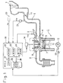
- FIG. 1 is a schematic view of the configuration showing an engine to which an engine control device according to a first embodiment of the present invention is applied and its peripheral equipment.
- reference numeral 1 is a single-cylinder water-cooled engine. Air from an air cleaner 3 is introduced into an intake passage 2 of the engine 1. In the middle of the intake passage 2 is provided a throttle valve 11 operating linked with operation of a not shown accelerator pedal etc. By the operation of the throttle valve 11, the amount of intake to the intake passage 2 (amount of intake air) is adjusted. At the same time as the amount of intake, fuel is injected and supplied to the engine 1 from an injector (fuel injector) provided in the intake passage 2 near the intake port 4. Further, an air-fuel mixture comprised of predetermined amounts of fuel and intake air is sucked into a fuel chamber 7 through an intake valve 6.
- an injector fuel injector
- a manifold pressure sensor 21 for detecting a manifold pressure PM in the intake passage 2.
- a crank shaft 21 of the engine 1 is provided with a crank angle sensor 22 for detecting a crank angle (°CA) accompanying its rotation.
- An engine speed NE of the engine 1 is calculated in accordance with the crank angle detected by the crank angle sensor 22.
- An atmospheric pressure sensor 23 is provided for detecting the atmospheric pressure PA in the ambient environment of the engine 1.
- a spark plug 13 is arranged facing the combustion chamber 7 of the engine 1.
- This spark plug 13 is supplied with a high voltage from an ignition coil/ignitor 14 based on an ignition command signal output from a later explained ECU (electronic control unit) in synchronization with a crank angle detected by the crank angle sensor 22 and ignites and burns the air-fuel mixture in the combustion chamber 7. In this way, the air-fuel mixture in the combustion chamber 7 is burned (expanded) and a drive force obtained.
- the exhaust gas after the combustion is led through the exhaust valve 8 from the exhaust manifold to the exhaust passage 9 and exhausted to the outside.
- the ECU 30 is comprised as a logical operational circuit consisting of a CPU 31 serving as the central processing unit for executing various known types of processing, a ROM 32 for storing a control program, a RAM 33 for storing various data, a B/U (backup) RAM 34, an input/output circuit 35, a bus line 36 for connecting these, etc.
- This ECU 30 receives as input a manifold pressure PM from the manifold pressure sensor 21, the crank angle from the crank angle sensor 22, the atmospheric pressure PA from the atmospheric pressure sensor 23, etc.
- the injector 5 is suitably controlled in fuel injection timing and fuel injection amount and the spark plug 13 and ignition coil/ignitor 14 etc. are suitably controlled in ignition timing.
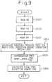
- step S101 the engine speed NE of the engine 1 is read.
- step S102 the atmospheric pressure PA is read.
- step S103 the manifold pressure PM is read.
- step S104 the manifold pressure PMTP for basic fuel injection amount operation (hereinafter simply referred to as the "operation use manifold pressure") is calculated by the following formula (1) based on the manifold pressure PM read at step S103: PMTP ⁇ f(PM)
- step S106 the final fuel injection amount TAU is calculated based on the manifold pressure compensation value PMTP' calculated at step S105 and the engine speed NE read at step S101, then the routine is ended.
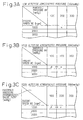
- the map shown in FIG. 3A is used to calculate the fuel injection amount ⁇ at the time of a low altitude atmospheric pressure of 760 mmHg for when the read value of the manifold pressure PM is 200 mmHg and the read value of the engine speed NE is 1000 rpm.
- the high altitude atmospheric pressure becomes 660 mmHg in the operating state of the engine 1
- the read value of the manifold pressure PM ends up becoming 100 mmHg, so the fuel injection amount ⁇ is calculated based on the read value of the manifold pressure PM of 100 mmHg and the read value of the engine speed NE of 1000 rpm.
- the fuel injection amount ⁇ is calculated from the manifold pressure compensation value PMTP' of 200 mmHg, obtained by adding the difference between the low altitude atmospheric pressure of 760 mmHg and high altitude atmospheric pressure of 660 mmHg, that is, the change in atmospheric pressure of 100 mmHg, to the high altitude manifold pressure 100 mmHg, and the engine speed NE of 1000 rpm. That is, the fuel injection amount ⁇ at the time of the high altitude atmospheric pressure of 660 mmHg in the present embodiment is set equal to the fuel injection amount ⁇ at the time of the low altitude atmospheric pressure of 760 mmHg.
- the change in the manifold pressure PM is suitably compensated, and the final fuel injection amount TAU at the atmospheric pressure PA at the current location, that is, the high altitude atmospheric pressure of 660 mmHg, is calculated based on the atmospheric pressure PAbase at the base location, that is, the low altitude atmospheric pressure of 760 mmHg. Therefore, even when changing from the low altitude atmospheric pressure to the high altitude atmospheric pressure, the operating state of the engine 1 can be maintained well without being influenced by the change in atmospheric pressure and the drivability can be secured.
- the engine control device of the present embodiment is provided with the atmospheric pressure sensor 23 serving as the atmospheric pressure detecting means for detecting the atmospheric pressure PA; the manifold pressure sensor 21 serving as the manifold pressure detecting means for detecting the pressure of the intake air introduced into the intake passage 2 of the engine 1, that is, the manifold pressure PM; the manifold pressure operating means realized by the ECU 30 for calculating the operation use manifold pressure PMTP for calculating the fuel injection amount of the engine 1 based on the manifold pressure PM detected by the manifold pressure detecting sensor 21; the crank angle sensor 22 serving as the rotational speed detecting means for detecting the engine speed NE of the engine 1; the change operating means realized by the ECU 30 for calculating the difference between the atmospheric pressure PAbase at the base location detected by the atmospheric pressure sensor 23 and the atmospheric pressure PA at the current location as the change in atmospheric pressure PAdev; and the injection amount operating means realized by the ECU 30 for calculating the final fuel injection amount TAU to be supplied to the engine 1 using as parameters the manifold pressure compensation value
- the final fuel injection amount TAU to be supplied to the engine 1 is calculated using as parameters the manifold pressure compensation value PMTP' found by adding the difference between the base atmospheric pressure PAbase and the current atmospheric pressure PA detected by the atmospheric pressure sensor 23, that is, the change in atmospheric pressure PAdev, and the operation use manifold pressure PMTP for calculating the fuel injection amount of the engine 1 based on the manifold pressure PM detected by the manifold pressure sensor 21 and the engine speed NE detected by the crank angle sensor 22.
- the change in atmospheric pressure PAdev with respect to the manifold pressure compensation value PMTP' and reflecting it into the manifold pressure parameter, it is possible to supply a suitable final fuel injection amount TAU regardless of the change in atmospheric pressure.
- the difference between the base atmospheric pressure PAbase and the current atmospheric pressure PA is used as it is as the change in atmospheric pressure PAdev for calculation of the fuel injection amount, but it is also possible to multiply for example 0.8 as a predetermined compensation coefficient based on compliance with the difference between the base atmospheric pressure PAbase and atmospheric pressure PA at the current location to obtain the change in atmospheric pressure PAdev.
- the change operating means realized by the ECU 30 of the engine control device multiplies a predetermined compensation coefficient with the difference to calculate the change in atmospheric pressure PAdev and can expect actions and effects similar to the above embodiment.
- the difference between the base atmospheric pressure PAbase and the current atmospheric pressure PA is used as it is as the change in atmospheric pressure PAdev for calculation of the fuel injection amount, but it is also possible to multiply a predetermined compensation coefficient (1.0, 0.9, 0.8, ...) having as a parameter the manifold pressure PM (100, 200, 300,%) as the one-dimensional map based on compliance with the difference between the base atmospheric pressure PAbase and atmospheric pressure PA at the current location to obtain the change in atmospheric pressure PAdev.
- the change operating means realized by the ECU 30 of the engine control device multiplies a predetermined compensation coefficient having the manifold pressure PM as a parameter with the difference to calculate the change in atmospheric pressure PAdev and can expect actions and effects similar to the above embodiment.
- the above embodiment is configured provided with the atmospheric sensor 23 to detect the atmospheric pressure PA in the ambient environment of the engine 1, but it is also possible to calculate the atmospheric pressure PA based on the manifold pressure PM detected by the manifold pressure sensor 21 at a predetermined timing. In this case, the atmospheric pressure sensor 23 is not required.
- This engine control device is provided with the manifold pressure sensor 21 serving as the manifold pressure detecting means for detecting the pressure of the intake air introduced into the intake passage 2 of the engine 1, that is, the manifold pressure PM; the manifold pressure operating means realized by the ECU 30 for calculating the operation use manifold pressure PMTP for calculating the fuel injection amount of the engine 1 based on the manifold pressure PM detected by the manifold pressure sensor 21; the atmospheric pressure operating means realized by the ECU 30 for calculating the atmospheric pressure PA based on the manifold pressure PM detected by the manifold pressure sensor 21; the crank angle sensor 22 serving as the rotational speed detecting means for detecting the engine speed NE of the engine 1; the change operating means realized by the ECU 30 for calculating the difference between the base atmospheric pressure PAbase and the atmospheric pressure PA at the current location calculated by the atmospheric pressure operating means as the change in atmospheric pressure PAdev; and the injection amount operating means realized by the ECU 30 for calculating the final fuel injection amount TAU to be supplied to the engine 1 using as parameters the manif
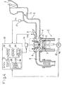
- FIG. 4 is a schematic view of the configuration showing an engine to which an engine control device according to the second embodiment of the present invention is applied and its peripheral equipment. Only the atmospheric pressure sensor 23 for detecting the atmospheric pressure PA in the ambient environment of the engine 1 in FIG. 1 showing a schematic view of the configuration of the above first embodiment is removed. A detailed explanation will therefore be omitted.
- step S201 it is judged if there an N signal interruption.
- This "N signal” is a signal output every 30° CA by the crank angle sensor 22 of the crank shaft 12 of the engine 1.
- the routine waits until there is an N signal interruption at step S201. It then proceeds to step S202, where "1" is added to the interruption number NNUM0 of the previous N signal, that is, the N signal interruption number NNUM is incremented by "+1".
- This N signal interruption number NNUM is a signal expressing crank angle positions "0" to "23” given for every 30°CA interval of the range of crank angle 720°CA comprised of four cycles (suction stroke ⁇ compression stroke ⁇ expansion (explosion) stroke ⁇ exhaust stroke) starting with the base crank angle position detected by the crank angle sensor 22 provided at the crank shaft 12 of the engine 1 as “0 (zero”).
- step S203 the routine proceeds to step S203, where it is judged if Na ⁇ NNUM ⁇ Nb.
- the routine proceeds to step S204, where it is judged that the timing is the atmospheric pressure detection timing and the later explained atmospheric pressure detection processing is executed.
- the judgement condition of step S203 does not stand, that is, the N signal interruption number NNUM is not between the preset constant Na and constant Nb, the routine proceeds to step S205, where it is judged if Nc ⁇ NNUM ⁇ Nd.
- step S205 When the judgement condition of step S205 stands, that is, the N signal interruption number NNUM is between a preset constant Nc and constant Nd, the routine proceeds to step S206, where it is judged that the timing is the manifold pressure detection timing and the later explained manifold pressure detection processing is executed.
- the routine returns to the above step S201, where similar processing is repeatedly executed.
- step S207 When the judgement condition of step S207 stands, that is, the N signal interruption number NNUM becomes equal to a preset constant Ne, the routine proceeds to step S208, where the N signal interruption number NNUM is cleared to "0", then the routine proceeds to the above step S201, where the same processing is repeatedly executed.
- step S301 the manifold pressure PM is read.
- step S301 the routine proceeds to step S302, where the manifold pressure PM read at step S301 is made the atmospheric pressure detection value PAi. That is, in the present embodiment, the pressure value based on the manifold pressure PM detected by the manifold pressure sensor 21 is used as the atmospheric pressure PA. Note that "i” is a number matching with the N signal interruption number NNUM.
- step S303 it is judged if "i" is equal to Nb.
- the judgement condition of step S303 does not stand, that is, "i" is not equal to Nb, the atmospheric pressure detection value PAi from step S302 is stored, then the routine is ended.
- step S303 when the judgement condition at step S303 stands, that is, "i" becomes equal to Nb, the routine proceeds to step S304, where the average value obtained by dividing the total ⁇ PAi of the atmospheric pressure detection values PAi stored at step S302 by the number NPA is made the atmospheric pressure PA.
- step S305 the routine proceeds to step S305, where all of the manifold pressure detection values PMi are cleared to "0", then the routine is ended.
- step S401 the manifold pressure PM is read.
- step S402 the manifold pressure PM read at step S401 is made the manifold pressure detection value PMi.
- "i" is a number matching with the N signal interruption number NNUM.
- step S403 it is judged if "i" is equal to Nd.
- step S403 when the judgement condition at step S403 stands, that is, "i" becomes equal to Nd, the routine proceeds to step S404, where the value according to the manifold pressure calculation function f(PMi) in which the manifold pressure detection value PMi stored at step S402 is entered is made the manifold pressure calculation value PML. Note that the manifold pressure calculation value PML is treated simply as the "manifold pressure PM" in the subsequent flow charts. Next, the routine proceeds to step S405, where all of the manifold pressure detection values PMi are cleared to "0", then the routine is ended.
- step S501 the engine speed NE of the engine 1 is read.
- step S502 the atmospheric pressure PA found by the above-mentioned atmospheric pressure detection routine is read.
- step S503 the manifold pressure PM found by the above manifold pressure detection routine is read.
- step S504 the operation use manifold pressure PMTP is calculated by the above formula (1) based on the manifold pressure PM read at step S503.
- step S505 the routine proceeds to step S505, where the value of the atmospheric pressure calculation function f(PA) in which the atmospheric pressure PA read at step S502 is entered and the value of the atmospheric pressure calculation function f(PA0) in which the predetermined atmospheric pressure PAO is entered are multiplied with the operation use manifold pressure PMTP calculated at step S504 to calculate the manifold pressure compensation value PMTP' by the following formula (3): PMTP' ⁇ PMTP•f(PA)•f(PA0)
- step S506 the final fuel injection amount TAU is calculated based on the manifold pressure compensation value PMTP' calculated at step S505 and the engine speed NE read at step S501 and the routine is ended.
- the calculation of the final fuel injection amount TAU using as parameters the manifold pressure compensation value PMTP' (mmHg) and the engine speed NE (rpm) by the fuel injection amount operation routine is similar to that of the above embodiment, so the explanation will be omitted.
- the engine control device of the present embodiment is provided with the manifold pressure sensor 21 serving as the manifold pressure detecting means for detecting the pressure of the intake air introduced into the intake passage 2 of the engine 1, that is, the manifold pressure PM; the manifold pressure operating means realized by the ECU 30 for calculating the operation use manifold pressure PMTP for calculating the fuel injection amount of the engine 1 based on the manifold pressure PM detected by the manifold pressure sensor 21; the atmospheric pressure operating means realized by the ECU 30 for calculating the atmospheric pressure PA based on the manifold pressure PM detected by the manifold pressure sensor 21; the crank angle sensor 22 serving as the rotational speed detecting means for detecting the engine speed NE of the engine 1; the compensation value operating means realized by the ECU 30 for compensating the operation use manifold pressure PMTP calculated by the manifold pressure operating means by the atmospheric pressure PA calculated by the atmospheric pressure operating means and the predetermined atmospheric pressure PAO and calculating the result as the manifold pressure compensation value PMTP'; and the injection amount operating means
- the operation use manifold pressure value PMTP for calculating the fuel injection amount of the engine 1 based on the manifold pressure PM detected by the manifold pressure sensor 21 is compensated by the atmospheric pressure PA calculated based on the manifold pressure PM and the predetermined atmospheric pressure PAO, and the final fuel injection amount TAU to be supplied to the engine 1 is calculated using as parameters the manifold pressure compensation value PMTP' and the engine speed NE detected by the crank angle sensor 22.
- the optimal manifold pressure compensation value regardless of the change in atmospheric pressure and supply a suitable final fuel injection amount TAU by this manifold pressure compensation value.
- step S601 to step S604 correspond to step S501 to step S504 in the above embodiment, so a detailed description will be omitted.
- step S605 the value obtained by dividing the predetermined atmospheric pressure PAO by the atmospheric pressure PA read at step S602 is multiplied with the operation use manifold pressure PMTP calculated at step S604 to calculate the manifold pressure compensation value PMTP' by the following formula (4): PMTP' ⁇ PMTP ⁇ (PA0/PA)
- step S606 the final fuel injection amount TAU is calculated based on the manifold pressure compensation value PMTP' calculated at step S605 and the engine speed NE read at step S601 and the routine is ended.
- the calculation of the final fuel injection amount TAU using as parameters the manifold pressure compensation value PMTP' (mmHg) and the engine speed NE (rpm) by the fuel injection amount operation routine is similar to that of the above embodiment, so the explanation will be omitted.
- the operation use manifold pressure compensation value PMTP' in the compensation value operating means realized by the ECU 30 of the engine control device of the present modification is calculated by multiplying a value obtained by dividing a predetermined atmospheric pressure PA0 by the atmospheric pressure PA with the operation use manifold pressure PMTP. That is, by taking into consideration the change in atmospheric pressure with respect to the manifold pressure compensation value PMTP' and reflecting this into the manifold pressure parameter, it is possible to calculate the optimal manifold pressure compensation value PMTP' for setting the final fuel injection amount TAU regardless of the change in atmospheric pressure.
- step S701 to step S704 correspond to step S501 to step S504 in the above embodiment, so a detailed description will be omitted.
- step S705 the value obtained by dividing the predetermined atmospheric pressure PAO multiplied with a predetermined compensation coefficient ⁇ by the atmospheric pressure PA read at step S702 is multiplied with the operation use manifold pressure PMTP calculated at step S704 to calculate the manifold pressure compensation value PMTP' by the following formula (5): PMTP' ⁇ PMTP• ⁇ (PA0)/PA ⁇
- step S706 the final fuel injection amount TAU is calculated based on the manifold pressure compensation value PMTP' calculated at step S705 and the engine speed NE read at step S701 and the routine is ended.
- the calculation of the final fuel injection amount TAU using as parameters the manifold pressure compensation value PMTP' (mmHg) and the engine speed NE (rpm) by the fuel injection amount operation routine is similar to that of the above embodiment, so the explanation will be omitted.
- the manifold pressure compensation value PMTP' in the compensation value operating means realized by the ECU 30 of the engine control device of the present modification is calculated by multiplying a value obtained by dividing a predetermined atmospheric pressure PA0 multiplied with a predetermined compensation coefficient ⁇ by the atmospheric pressure PA with the operation use manifold pressure PMTP. That is, by taking into consideration the change in atmospheric pressure with respect to the manifold pressure compensation value PMTP' and reflecting this into the manifold pressure parameter, it is possible to calculate the optimal manifold pressure compensation value PMTP' for setting the final fuel injection amount TAU regardless of the change in atmospheric pressure.
- step S801 to step S804 correspond to step S501 to step S504 in the above embodiment, so a detailed description will be omitted.
- step S805 the value obtained by multiplying a predetermined compensation coefficient ⁇ with the difference between the predetermined atmospheric pressure PAO and the atmospheric pressure PA read at step S802 is added to the operation use manifold pressure PMTP calculated at step S804 to calculate the manifold pressure compensation value PMTP' by the following formula (6): PMTP' ⁇ PMTP+ ⁇ (PA0-PA)
- step S806 the final fuel injection amount TAU is calculated based on the manifold pressure compensation value PMTP' calculated at step S805 and the engine speed NE read at step S801 and the routine is ended.
- the calculation of the final fuel injection amount TAU using as parameters the manifold pressure compensation value PMTP' (mmHg) and the engine speed NE (rpm) by the fuel injection amount operation routine is similar to that of the above embodiment, so the explanation will be omitted.
- the manifold pressure compensation value PMTP' in the compensation value operating means realized by the ECU 30 of the engine control device of the present modification is calculated by adding a value obtained by multiplying a predetermined compensation coefficient ⁇ with the difference between the predetermined atmospheric pressure PAO and atmospheric pressure PA to the operation use manifold pressure PMTP. That is, by taking into consideration the change in atmospheric pressure with respect to the manifold pressure compensation value PMTP' and reflecting this into the manifold pressure parameter, it is possible to calculate the optimal manifold pressure compensation value PMTP' for setting the final fuel injection amount TAU regardless of the change in atmospheric pressure.
- FIG. 13 is a map for calculating by interpolation the predetermined compensation coefficient ⁇ from the operation use manifold pressure PMTP and engine speed NE. Note that this fuel injection amount operation routine is repeatedly executed by the CPU 31 every predetermined time interval.
- step S901 to step S904 correspond to step S501 to step S504 in the above embodiment, so a detailed description will be omitted.
- step S905 the map shown in FIG. 13 is used for calculation of a predetermined compensation coefficient ⁇ from the operation use manifold pressure PMTP and engine speed NE by known four-point interpolation.
- step S906 the value obtained by multiplying a predetermined compensation coefficient ⁇ calculated at step S905 with the difference between the predetermined atmospheric pressure PAO and the atmospheric pressure PA read at step S902 is added to the operation use manifold pressure PMTP calculated at step S904 to calculate the manifold pressure compensation value PMTP' by the following formula (7): PMTP' ⁇ PMTP+ ⁇ (PA0-PA)
- step S907 the final fuel injection amount TAU is calculated based on the manifold pressure compensating value PMTP' calculated at step S906 and the engine speed NE read at step S901 and the routine is ended.
- the calculation of the final fuel injection amount TAU using as parameters the manifold pressure compensation value PMTP' (mmHg) and the engine speed NE (rpm) by the fuel injection amount operation routine is similar to that of the above embodiment, so the explanation will be omitted.
- the manifold pressure compensation value PMTP' in the compensation value operating means realized by the ECU 30 of the engine control device of the present modification is calculated by adding a value obtained by multiplying a predetermined compensation coefficient ⁇ with the difference between the predetermined atmospheric pressure PAO and atmospheric pressure PA to the operation use manifold pressure PMTP. Further, the predetermined compensation coefficient ⁇ of the present modification is calculated using as parameters the operation use manifold pressure PMTP and engine speed NE.
Landscapes
- Engineering & Computer Science (AREA)
- Chemical & Material Sciences (AREA)
- Combustion & Propulsion (AREA)
- Mechanical Engineering (AREA)
- General Engineering & Computer Science (AREA)
- Electrical Control Of Air Or Fuel Supplied To Internal-Combustion Engine (AREA)
- Combined Controls Of Internal Combustion Engines (AREA)
Abstract
Description
Claims (10)
- An engine control device provided with:manifold pressure detecting means for detecting pressure of intake air introduced into an intake passage of an engine, that is, manifold pressure;manifold pressure operating means for calculating operation use manifold pressure for calculating a fuel injection amount of an engine based on manifold pressure detected by said manifold pressure detecting means;atmospheric pressure operating means for calculating an atmospheric pressure based on a manifold pressure detected by said manifold pressure detecting means;rotational speed detecting means for detecting an engine speed of said engine;change operating means for calculating the difference between a base atmospheric pressure and a current atmospheric pressure calculated by said atmospheric pressure operating means as the change in atmospheric pressure; andinjection amount operating means for calculating a fuel injection amount to be supplied to said engine using as parameters a manifold pressure compensation value obtained by adding the change in atmospheric pressure calculated by said change operating means to said operation use manifold pressure calculated by said manifold pressure operating means and the engine speed detected by said rotational speed detecting means.
- An engine control device provided with:atmospheric pressure detecting means for detecting an atmospheric pressure;manifold pressure detecting means for detecting pressure of intake air introduced into an intake passage of an engine, that is, manifold pressure;manifold pressure operating means for calculating an operation use manifold pressure for calculating a fuel injection amount of said engine based on a manifold pressure detected by said manifold pressure detecting means;rotational speed detecting means for detecting an engine speed of said engine;change operating means for calculating the difference between a base atmospheric pressure and a current atmospheric pressure detected by said atmospheric pressure detecting means as the change in atmospheric pressure; andinjection amount operating means for calculating a fuel injection amount to be supplied to said engine using as parameters a manifold pressure compensation value obtained by adding the change in atmospheric pressure calculated by said change operating means to said operation use manifold pressure calculated by said manifold pressure operating means and the engine speed detected by said rotational speed detecting means.
- An engine control device as set forth in claim 1 or 2, wherein said change operating means multiplies a predetermined compensation coefficient with said difference to calculate said change in atmospheric pressure
- An engine control device as set forth in claim 1 or 2, wherein said change operating means multiplies a predetermined compensation coefficient using a manifold pressure as a parameter with said difference to calculate said change in atmospheric pressure.
- An engine control device provided with:manifold pressure detecting means for detecting a pressure of intake air introduced into an intake passage of an engine, that is, a manifold pressure;manifold pressure operating means for calculating an operation use manifold pressure for calculating a fuel injection amount of an engine based on a manifold pressure detected by said manifold pressure detecting means;atmospheric pressure operating means for calculating an atmospheric pressure based on a manifold pressure detected by said manifold pressure detecting means;rotational speed detecting means for detecting an engine speed of said engine;compensation value operating means for compensating the operation use manifold pressure calculated by said manifold pressure operating means by the atmospheric pressure calculated by said atmospheric pressure operating means and a predetermined atmospheric pressure to calculate a manifold pressure compensation value; andinjection amount operating means for calculating a fuel injection amount to be supplied to said engine using as parameters the manifold pressure compensation value calculated by said compensation value operating means and the engine speed detected by said rotational speed detecting means.
- An engine control device as set forth in claim 5, wherein said manifold pressure compensation value in said compensation value operating means is calculated by multiplying the compensation value using as a parameter the atmospheric pressure calculated by said atmospheric pressure operating means and said compensation value based on a predetermined atmospheric pressure with said operation use manifold pressure.
- An engine control device as set forth in claim 5, wherein said manifold pressure compensation value in said compensation value operating means is calculated by multiplying a value obtained by dividing said predetermined atmospheric pressure by an atmospheric pressure calculated by said atmospheric pressure operating means with said operation use manifold pressure.
- An engine control device as set forth in claim 5, wherein said manifold pressure compensation value in said compensation value operating means is calculated by multiplying a value obtained by dividing said predetermined atmospheric pressure multiplied with a predetermined compensation coefficient by the atmospheric pressure calculated by said atmospheric pressure operating means with said operation use manifold pressure.
- An engine control device as set forth in claim 5, wherein said manifold pressure compensation value in said compensation value operating means is calculated by adding a value obtained by multiplying a predetermined compensation coefficient with a difference between said predetermined atmospheric pressure and the atmospheric pressure calculated by said atmospheric pressure operating means to said operation use manifold pressure.
- An engine control device as set forth in claim 8 or 9, wherein said predetermined compensation coefficient is calculated using as parameters said operation use manifold pressure and said engine speed.
Applications Claiming Priority (5)
| Application Number | Priority Date | Filing Date | Title |
|---|---|---|---|
| JP2001302790 | 2001-09-28 | ||
| JP2001302790 | 2001-09-28 | ||
| JP2002268385 | 2002-09-13 | ||
| JP2002268385A JP4401635B2 (en) | 2001-09-28 | 2002-09-13 | Control device for internal combustion engine |
| PCT/JP2002/010107 WO2003029636A1 (en) | 2001-09-28 | 2002-09-27 | Controller for internal combustion engine |
Publications (3)
| Publication Number | Publication Date |
|---|---|
| EP1431551A1 true EP1431551A1 (en) | 2004-06-23 |
| EP1431551A4 EP1431551A4 (en) | 2004-11-10 |
| EP1431551B1 EP1431551B1 (en) | 2006-04-26 |
Family
ID=26623380
Family Applications (1)
| Application Number | Title | Priority Date | Filing Date |
|---|---|---|---|
| EP02772943A Expired - Lifetime EP1431551B1 (en) | 2001-09-28 | 2002-09-27 | Controller for internal combustion engine |
Country Status (4)
| Country | Link |
|---|---|
| EP (1) | EP1431551B1 (en) |
| JP (1) | JP4401635B2 (en) |
| CN (1) | CN100594298C (en) |
| WO (1) | WO2003029636A1 (en) |
Cited By (2)
| Publication number | Priority date | Publication date | Assignee | Title |
|---|---|---|---|---|
| EP1930576A3 (en) * | 2006-12-08 | 2011-04-13 | Keihin Corporation | Control Apparatus and Method for Internal Combustion Engine |
| EP3425211A4 (en) * | 2016-09-28 | 2020-01-22 | Hitachi Construction Machinery Co., Ltd. | WORKING VEHICLE |
Families Citing this family (5)
| Publication number | Priority date | Publication date | Assignee | Title |
|---|---|---|---|---|
| JP4014580B2 (en) * | 2004-04-02 | 2007-11-28 | 株式会社ケーヒン | Ignition timing control device for internal combustion engine |
| US7413043B2 (en) * | 2006-08-14 | 2008-08-19 | Gm Global Technology Operations, Inc. | Method and system for estimating barometric pressure in a hybrid vehicle |
| JP2008045506A (en) * | 2006-08-18 | 2008-02-28 | Nikki Co Ltd | Engine control atmospheric pressure correction method and control device therefor |
| US9435283B2 (en) * | 2013-12-03 | 2016-09-06 | Ford Global Technologies, Llc | Method for inferring barometric pressure at low throttle angles |
| JP7256470B2 (en) * | 2019-11-18 | 2023-04-12 | トヨタ自動車株式会社 | engine controller |
Family Cites Families (8)
| Publication number | Priority date | Publication date | Assignee | Title |
|---|---|---|---|---|
| JPS61185646A (en) * | 1985-02-12 | 1986-08-19 | Nippon Denso Co Ltd | Control device for internal-combustion engine |
| JPS63159641A (en) * | 1986-12-23 | 1988-07-02 | Toyota Motor Corp | Fuel injection controller for internal combustion engine |
| JP2569586B2 (en) * | 1987-08-21 | 1997-01-08 | トヨタ自動車株式会社 | Electronic control unit for internal combustion engine |
| JPH0219626A (en) * | 1988-07-06 | 1990-01-23 | Toyota Motor Corp | Fuel injection control device for internal combustion engine |
| US5715796A (en) * | 1995-02-24 | 1998-02-10 | Honda Giken Kogyo Kabushiki Kaisha | Air-fuel ratio control system having function of after-start lean-burn control for internal combustion engines |
| JPH11200918A (en) * | 1997-11-17 | 1999-07-27 | Denso Corp | Fuel injection control device for internal combustion engine |
| JP3259712B2 (en) * | 1999-01-12 | 2002-02-25 | トヨタ自動車株式会社 | Control device for internal combustion engine |
| JP2000213401A (en) * | 1999-01-26 | 2000-08-02 | Denso Corp | Atmospheric pressure detector of internal combustion engine |
-
2002
- 2002-09-13 JP JP2002268385A patent/JP4401635B2/en not_active Expired - Fee Related
- 2002-09-27 WO PCT/JP2002/010107 patent/WO2003029636A1/en not_active Ceased
- 2002-09-27 CN CN02803040A patent/CN100594298C/en not_active Expired - Fee Related
- 2002-09-27 EP EP02772943A patent/EP1431551B1/en not_active Expired - Lifetime
Cited By (2)
| Publication number | Priority date | Publication date | Assignee | Title |
|---|---|---|---|---|
| EP1930576A3 (en) * | 2006-12-08 | 2011-04-13 | Keihin Corporation | Control Apparatus and Method for Internal Combustion Engine |
| EP3425211A4 (en) * | 2016-09-28 | 2020-01-22 | Hitachi Construction Machinery Co., Ltd. | WORKING VEHICLE |
Also Published As
| Publication number | Publication date |
|---|---|
| WO2003029636A1 (en) | 2003-04-10 |
| JP2003172172A (en) | 2003-06-20 |
| EP1431551A4 (en) | 2004-11-10 |
| EP1431551B1 (en) | 2006-04-26 |
| CN1476514A (en) | 2004-02-18 |
| JP4401635B2 (en) | 2010-01-20 |
| CN100594298C (en) | 2010-03-17 |
Similar Documents
| Publication | Publication Date | Title |
|---|---|---|
| EP1437498B1 (en) | 4−STROKE ENGINE CONTROL DEVICE AND CONTROL METHOD | |
| JPH094500A (en) | Control device for two-cycle cylinder fuel injection engine | |
| EP1818525B1 (en) | An air-fuel ratio controlling apparatus for an engine | |
| EP1431551B1 (en) | Controller for internal combustion engine | |
| EP1447551B1 (en) | Atmospheric pressure detection device of four-stroke engine and method of detecting atmospheric pressure | |
| EP1433944A1 (en) | Atmospheric pressure detector of internal combustion engine | |
| US7448360B2 (en) | Controller of internal combustion engine | |
| JP2004257386A (en) | Engine air amount prediction method based on engine position, control program for internal combustion engine, and control system for internal combustion engine | |
| EP0161611B1 (en) | Method and apparatus for controlling air-fuel ratio in internal combustion engine | |
| EP1650417A2 (en) | Control device of internal combustion engine | |
| JP4236556B2 (en) | Fuel injection control device for internal combustion engine | |
| JP3963099B2 (en) | Operating state discrimination device for internal combustion engine | |
| JP2000170590A (en) | Internal combustion engine control device | |
| JP2006009632A (en) | Control device for internal combustion engine | |
| US6705288B2 (en) | Starting control apparatus for internal combustion engine | |
| EP1930576A2 (en) | Control Apparatus and Method for Internal Combustion Engine | |
| JP4269931B2 (en) | In-cylinder pressure measuring device and in-cylinder pressure measuring method | |
| JP4052025B2 (en) | Atmospheric pressure detection device for internal combustion engine | |
| JP4192825B2 (en) | Control device for internal combustion engine | |
| JP2008070232A (en) | Control device for internal combustion engine | |
| JP2005201163A (en) | Control device for internal combustion engine | |
| JPH03286167A (en) | Misfire detecting device for two-cycle internal combustion engine | |
| JP2006316655A (en) | Control device for internal combustion engine | |
| JP2013053554A (en) | Control device for internal-combustion engine | |
| JPH09133042A (en) | In-cylinder pressure detection device for internal combustion engine |
Legal Events
| Date | Code | Title | Description |
|---|---|---|---|
| PUAI | Public reference made under article 153(3) epc to a published international application that has entered the european phase |
Free format text: ORIGINAL CODE: 0009012 |
|
| 17P | Request for examination filed |
Effective date: 20030522 |
|
| AK | Designated contracting states |
Kind code of ref document: A1 Designated state(s): AT BE BG CH CY CZ DE DK EE ES FI FR GB GR IE IT LI LU MC NL PT SE SK TR |
|
| A4 | Supplementary search report drawn up and despatched |
Effective date: 20040928 |
|
| 17Q | First examination report despatched |
Effective date: 20041126 |
|
| REG | Reference to a national code |
Ref country code: DE Ref legal event code: 8566 |
|
| GRAP | Despatch of communication of intention to grant a patent |
Free format text: ORIGINAL CODE: EPIDOSNIGR1 |
|
| GRAS | Grant fee paid |
Free format text: ORIGINAL CODE: EPIDOSNIGR3 |
|
| GRAA | (expected) grant |
Free format text: ORIGINAL CODE: 0009210 |
|
| AK | Designated contracting states |
Kind code of ref document: B1 Designated state(s): IT |
|
| RBV | Designated contracting states (corrected) |
Designated state(s): IT |
|
| RIN1 | Information on inventor provided before grant (corrected) |
Inventor name: NAGATA, KOUICHI,DENSO CORPORATION Inventor name: KOBAYASHI, FUMIO Inventor name: OKOCHI, YASUHIRO Inventor name: DOMYO, MASAHISA Inventor name: KURODA, TAKAHIKO |
|
| PLBE | No opposition filed within time limit |
Free format text: ORIGINAL CODE: 0009261 |
|
| STAA | Information on the status of an ep patent application or granted ep patent |
Free format text: STATUS: NO OPPOSITION FILED WITHIN TIME LIMIT |
|
| 26N | No opposition filed |
Effective date: 20070129 |
|
| PGFP | Annual fee paid to national office [announced via postgrant information from national office to epo] |
Ref country code: IT Payment date: 20200922 Year of fee payment: 19 |
|
| PG25 | Lapsed in a contracting state [announced via postgrant information from national office to epo] |
Ref country code: IT Free format text: LAPSE BECAUSE OF NON-PAYMENT OF DUE FEES Effective date: 20210927 |