EP1930576A2 - Control Apparatus and Method for Internal Combustion Engine - Google Patents
Control Apparatus and Method for Internal Combustion Engine Download PDFInfo
- Publication number
- EP1930576A2 EP1930576A2 EP07122156A EP07122156A EP1930576A2 EP 1930576 A2 EP1930576 A2 EP 1930576A2 EP 07122156 A EP07122156 A EP 07122156A EP 07122156 A EP07122156 A EP 07122156A EP 1930576 A2 EP1930576 A2 EP 1930576A2
- Authority
- EP
- European Patent Office
- Prior art keywords
- control
- atmospheric pressure
- internal combustion
- combustion engine
- scale values
- Prior art date
- Legal status (The legal status is an assumption and is not a legal conclusion. Google has not performed a legal analysis and makes no representation as to the accuracy of the status listed.)
- Granted
Links
- 238000002485 combustion reaction Methods 0.000 title claims abstract description 40
- 238000000034 method Methods 0.000 title claims description 11
- 239000000446 fuel Substances 0.000 claims description 47
- 238000002347 injection Methods 0.000 description 47
- 239000007924 injection Substances 0.000 description 47
- 239000000498 cooling water Substances 0.000 description 10
- QVGXLLKOCUKJST-UHFFFAOYSA-N atomic oxygen Chemical compound [O] QVGXLLKOCUKJST-UHFFFAOYSA-N 0.000 description 9
- 239000001301 oxygen Substances 0.000 description 9
- 229910052760 oxygen Inorganic materials 0.000 description 9
- 238000007493 shaping process Methods 0.000 description 4
- 239000003054 catalyst Substances 0.000 description 2
- 238000010586 diagram Methods 0.000 description 2
- 239000007789 gas Substances 0.000 description 2
- 230000007423 decrease Effects 0.000 description 1
- 239000002828 fuel tank Substances 0.000 description 1
- 208000015181 infectious disease Diseases 0.000 description 1
- XLYOFNOQVPJJNP-UHFFFAOYSA-N water Substances O XLYOFNOQVPJJNP-UHFFFAOYSA-N 0.000 description 1
Images

Classifications
-
- F—MECHANICAL ENGINEERING; LIGHTING; HEATING; WEAPONS; BLASTING
- F02—COMBUSTION ENGINES; HOT-GAS OR COMBUSTION-PRODUCT ENGINE PLANTS
- F02D—CONTROLLING COMBUSTION ENGINES
- F02D41/00—Electrical control of supply of combustible mixture or its constituents
- F02D41/30—Controlling fuel injection
- F02D41/32—Controlling fuel injection of the low pressure type
-
- F—MECHANICAL ENGINEERING; LIGHTING; HEATING; WEAPONS; BLASTING
- F02—COMBUSTION ENGINES; HOT-GAS OR COMBUSTION-PRODUCT ENGINE PLANTS
- F02D—CONTROLLING COMBUSTION ENGINES
- F02D41/00—Electrical control of supply of combustible mixture or its constituents
- F02D41/24—Electrical control of supply of combustible mixture or its constituents characterised by the use of digital means
- F02D41/2406—Electrical control of supply of combustible mixture or its constituents characterised by the use of digital means using essentially read only memories
- F02D41/2425—Particular ways of programming the data
- F02D41/2429—Methods of calibrating or learning
- F02D41/2451—Methods of calibrating or learning characterised by what is learned or calibrated
-
- F—MECHANICAL ENGINEERING; LIGHTING; HEATING; WEAPONS; BLASTING
- F02—COMBUSTION ENGINES; HOT-GAS OR COMBUSTION-PRODUCT ENGINE PLANTS
- F02D—CONTROLLING COMBUSTION ENGINES
- F02D2200/00—Input parameters for engine control
- F02D2200/02—Input parameters for engine control the parameters being related to the engine
- F02D2200/04—Engine intake system parameters
- F02D2200/0406—Intake manifold pressure
-
- F—MECHANICAL ENGINEERING; LIGHTING; HEATING; WEAPONS; BLASTING
- F02—COMBUSTION ENGINES; HOT-GAS OR COMBUSTION-PRODUCT ENGINE PLANTS
- F02D—CONTROLLING COMBUSTION ENGINES
- F02D2200/00—Input parameters for engine control
- F02D2200/70—Input parameters for engine control said parameters being related to the vehicle exterior
- F02D2200/703—Atmospheric pressure
Definitions
- the present invention relates to a control apparatus for an internal combustion engine such as a fuel injection control apparatus and a control method for the same.
- a basic fuel amount required by an engine for combustion in its cylinder is known to correspond in characteristic to the opening degree of a throttle valve provided in the air-intake manifold and the rotation speed of the engine. Further, because intake pressure that occurs downstream of the throttle valve in the air-intake manifold changes almost proportional to the opening degree of the throttle valve, it is possible to search a data map for the basic fuel amount required by the engine based on the intake pressure and the rotation speed of the engine and to set an amount obtained by the search as the basic fuel amount.
- the intake pressure is influenced by atmospheric pressure
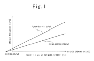
- the relationship between the opening degree of the throttle valve and the intake pressure differs between plains and highlands due to the difference in air density as shown in Fig. 1 .
- the intake pressure decreases as the altitude becomes higher.
- an appropriate basic fuel amount cannot be set by using the same data map as for plains. Accordingly, when an engine mounted on a vehicle is moved from a plain to a highland, the detected intake pressure value needs to be corrected for high altitude.
- the atmospheric pressure and the intake pressure are detected with use of sensors, a correction coefficient K1 corresponding to the detected value of the atmospheric pressure and a correction coefficient K2 corresponding to the detected value of the intake pressure are calculated, and the detected value of the intake pressure is corrected in accordance with the correction coefficients K1, K2 so that the corrected value of the intake pressure corresponds to an equivalent intake air amount at standard atmospheric pressure at plains (see Japanese Patent Application Laid-Open Publication No. H05-149187 ) .
- Another method of correcting for high altitude is to add an atmospheric pressure variation that is the difference between standard atmospheric pressure PAbase and current atmospheric pressure PA detected by an atmospheric pressure sensor to intake pressure PM detected by an intake pressure sensor (see Japanese Patent Application Laid-Open Publication No. 2003-172172 ).
- Searching a data map based on the intake pressure corrected for high altitude and the rotation speed of the engine to determine the basic fuel amount is usually performed in a conventional fuel injection apparatus.
- An object of the present invention is to provide a control apparatus and method for an internal combustion engine, which can reduce the load of an arithmetic element that performs operations for setting a controlled amount in accordance with the detected value of the intake amount.
- a control apparatus for an internal combustion engine comprises: intake pressure detecting means for detecting intake pressure in the internal combustion engine; storage means for storing a data map in which a plurality of scale values for the intake pressure are associated respectively with a plurality of control amounts for a predetermined control parameter of the internal combustion engine; control amount setting means for setting one of the control amounts in the data map corresponding to a detected value of the intake pressure by the intake pressure detecting means as a control amount of the predetermined control parameter; control means for controlling the control parameter of the internal combustion engine in accordance with the control amount set by the control amount setting means; atmospheric pressure detecting means for detecting atmospheric pressure at a place where the internal combustion engine exists; and scale value rewriting means for rewriting each of the plurality of scale values corresponding to the plurality of control amounts in the data map with a value based on a detected value of the atmospheric pressure by the atmospheric pressure detecting means.
- a control method for an internal combustion engine comprises: an intake pressure detecting step of detecting intake pressure in the internal combustion engine; a storage step of storing a data map where a plurality of scale values for the intake pressure are associated respectively with a plurality of control amounts for a predetermined control parameter of the internal combustion engine; a control amount setting step or setting one of the control amounts in the data map corresponding to a detected value of the intake pressure in the intake pressure detecting step as a control amount of the predetermined control parameter; a control step of controlling the control parameter of the internal combustion engine in accordance with the control amount set in the control amount setting step; an atmospheric pressure detecting step of detecting atmospheric pressure at the place where the internal combustion engine exists; and a scale value rewriting step of rewriting each of the plurality of scale values corresponding to the plurality of control amounts in the data map with a value based on a detected value of the atmospheric pressure in the atmospheric pressure detecting step.
- the data map is stored where the plurality of scale values for the intake pressure are associated respectively with the plurality of control amounts for the predetermined control parameter of the internal combustion engine, and each of the plurality of scale values corresponding to the plurality of control amounts in the data map is rewritten with a value based on a detected value of the atmospheric pressure.
- each of the plurality of scale values in the data map is rewritten with a value corresponding to the changed atmospheric pressure.
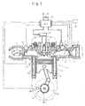
- Fig. 2 shows an engine control system for a four-cycle internal combustion engine to which the present invention is applied.
- a throttle valve 3 is provided in an intake manifold 2 coupled to the intake port of an engine body 1. Air taken in through an air cleaner 4 is supplied by an amount corresponding to the opening degree of the throttle valve 3 to the intake port of the engine body 1 through the intake manifold 2.
- a throttle sensor 5 is provided for the throttle valve 3 and detects the opening degree of the throttle valve 3.
- An injector (fuel injection valve) 6 is provided in the intake manifold 2 near the intake port of the engine body 1.
- a fuel pump sends fuel from a fuel tank (not shown) to the injector 6 by pressure.
- the intake manifold 2 is provided with an intake pressure sensor 7 and an intake temperature sensor 8.
- the intake pressure sensor 7 detects taken-in air pressure, i.e. intake pressure, in the intake manifold 2.
- the intake temperature sensor 8 detects a temperature of the taken-in air in the intake manifold 2.
- a catalyst 11 and an oxygen concentration sensor 12 are provided in an exhaust manifold 10 coupled to the exhaust port of the engine body 1.
- the catalyst 11 reduces unburned components in exhaust gas in the exhaust manifold 10.
- the oxygen concentration sensor 12 detects an oxygen concentration in the exhaust gas.
- An ignition plug 13 is fixed to the engine body 1 and connected to an igniting device 14.
- An ECU (electronic control unit) 15 described later issues an ignition timing instruction to the igniting device 14, thereby causing spark discharge to occur in the cylinder combustion chamber of the engine body 1.
- a cooling water passage 16a is formed in a cylinder block 16 forming the engine body 1.
- a cooling water temperature sensor 17 is provided in the cylinder block 16 and detects a temperature of cooling water in the cooling water passage 16a.
- the outputs of the throttle sensor 5, the intake pressure sensor 7, the intake temperature sensor 8, the oxygen concentration sensor 12, and the cooling water temperature sensor 17 are connected to the ECU 15.
- a crank angle sensor 19 and an atmospheric pressure sensor 20 which detects atmospheric pressure are connected to the ECU 15.
- the crank angle sensor 19 is provided for detecting a rotation angle position of a crankshaft 18 of the engine body 1.
- a plurality of protrusions are provided at predetermined angular intervals (e.g., 15 degrees) on the periphery of a rotor 19a rotating in association with the crankshaft 18, and a pickup 19b placed near the periphery of the rotor 19a magnetically or optically detects each of the protrusions.
- crank signal When one of the protrusions passes by the pickup 19b by rotation of the rotor 19a as well as the crankshaft 18, the pickup 19b generate a pulse (crank signal). The pulse is generated for each time the crankshaft 18 rotates through a predetermined angle.
- the crank angle sensor 19 outputs a signal indicating a reference angle to a CPU (central processing unit) 24, described later, in the ECU 15 for each time a piston 9 reaches the position of top dead center ; (TDC) or the crankshaft 18 rotates through 360 degrees.
- CPU central processing unit
- the throttle sensor 5, the intake pressure sensor 7, the intake temperature sensor 8, the oxygen concentration sensor 12, the cooling water temperature sensor 17, and the atmospheric pressure sensor 20 each output an analog voltage corresponding to their detected value.
- the injector 6 and igniting device 14 mentioned above are connected to the ECU 15.
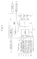
- the ECU 15 comprises a waveform shaping circuit 21, a counter 22, an A/D converter 23, a CPU 24, a drive circuit 25, ROM (read only memory) 26, RAM (random access memory) 27, and a timer 28.
- the waveform shaping circuit 21 shapes a pulse output from the crank angle sensor 19 into a rectangular pulse, for example and outputs the shaped pulse to the counter 22.
- the counter 22 counts pulses output from the waveform shaping circuit 21 and outputs data indicating the number of pulses per predetermined time to the CPU 24, which obtains engine rotation speed Ne from the number of pulses per predetermined time.
- the A/D converter 23 converts the analog voltages output from each of the throttle sensor 5, the intake pressure sensor 7, the intake temperature sensor 8, the oxygen concentration sensor 12, the cooling water temperature sensor 17, and the atmospheric pressure sensor 20, and the output voltage of a battery 30 into digital signals respectively and holds these signals.
- the digital signals are supplied to the CPU 24.
- the CPU 24 can read the opening degree qth of the throttle valve 3, intake pressure PM, intake temperature TA, oxygen concentration 02, cooling water temperature TW, atmospheric pressure PA, and battery voltage VB from the A/D converter 23 as well as the engine rotation speed Ne as detected values of engine parameters.
- the CPU 24 detects the rotation angle position at predetermined angular intervals of the crankshaft 18 based on the signal indicating the reference angle of the crank angle from the crank angle sensor 19 and the output pulses of the waveform shaping circuit 21.
- the CPU 24 performs fuel injection control and ignition time control in accordance with the detected values of the engine parameters and the rotation angle position at predetermined angular intervals of the crankshaft 18.
- the drive circuit 25 drives the injector 6 in accordance with a fuel injection instruction from the CPU 24 in the fuel injection control and drives the igniting device 14 in accordance with an energizing-ignition instruction from the CPU 24 in the ignition time control.
- Programs and data such as a data map for the fuel injection control and the ignition time control by the CPU 24 are previously written in the ROM 26.
- Data such as the detected values of the engine parameters and computed values including a fuel injection amount are written into the RAM 27 in the fuel injection control and the ignition time control by the CPU 24.
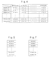
- a Ti-data map is formed in a table format as shown in Fig. 4 to calculate a basic injection amount Ti in accordance with the intake pressure PM and the engine rotation speed Ne for the fuel injection control.
- #PMINDX_N[0] to #PMINDX_N[19] indicate initial map axis scale values that are major values of the intake pressure PM
- #NEINDX_N[0] to #NEINDX_N[a] indicate map axis scale values that are major values of the engine rotation speed Ne.
- #TI[0, 0] to # TI[a, 19] indicate basic injection amounts Ti determined by the map axis scale values of the intake pressure PM and of the engine rotation speed Ne.
- Fig. 4 As shown in Fig.
- the RAM 27 has an area where the map axis scale values of #PMINDX_N[0] to #PMINDX_N[19] after correction are stored as PMINDEX[0] to PMINDEX[19].
- the PMINDEX[0] to PMINDEX[19] are associated by numbers in the square brackets with the #PMINDX_N[0] to #PMINDX_N[19] respectively.
- the timer 28 is also used by the CPU 24 to measure time points to issue the fuel injection instruction and the energizing-ignition instruction, but in this embodiment, only the timer 28 operating as an injector valve opening timer is shown.
- the CPU 24 executes a fuel injection control routine in interrupt processing synchronously with the rotation of the engine, for example, at a predetermined crank angle while executing a map axis correction routine, for example, in background processing at a predetermined cycle independently of the rotation of the engine.
- the CPU 24 reads a current atmospheric pressure PA from the A/D converter 23(step S0) and sets a correction coefficient MPA for the fuel injection control in accordance with the read atmospheric pressure PA (step S1). Then, the CPU 24 sets a map axis correction coefficient MPMIDXH for a high load in accordance with the atmospheric pressure PA (step S2) and sets a map axis correction coefficient MPMIDXL for a low load in accordance with the atmospheric pressure PA (step 33).
- These correction coefficients MPA, MPMIDXH, and MPMIDXL are decided uniquely using data maps (not shown).
- the CPU 29 places the content of a flag F_RENEWIDX into a flag F_REIDXINH (step S4) and resets the flag F_RENEWIDX to zero (step S5).
- the flag F_RENEWIDX is used to indicate that a map axis update has occurred.
- the CPU 24 sets a variable Index to zero (step S6) and determines whether the Index is greater than the maximum value of a low-load INDEX (step 37).
- the Index indicates the number of scale values for the intake air amount in the Ti-data map, e.g., a value of 0 to 19.
- the maximum value of the low-load INDEX is a threshold value for distinguishing a low load area and a high load area in the Ti-data map.
- the initial map axis scale value #PMINDX_N [Index] multiplied by the low-load map axis correction coefficient MPMIDXL is set as a corrected map axis scale value PMINDXB[Index] (step S8).
- the initial map axis scale value #PMINDX_N[Index] multiplied by the high-load map axis correction coefficient MPMIDXH is set as the corrected map axis scale value PMINDXB[Index] (step S9).
- the initial map axis scale value #PMINDX_N[Index] is previously recorded in the ROM 26 as mentioned above.
- step S10 the Index is incremented by 1 (step S10), and it is determined whether the Index is greater than the maximum value of a high-load INDEX (step S11).
- the maximum value of the high-load INDEX is the upper limit, e.g. 19, of the high load area in the Ti-data map. If the Index ⁇ the maximum value of the high-load INDEX, the process returns to step S7 and performs the operation of setting as the corrected map axis scale value PMINDXB[Index]. If the Index > the maximum value of the high-load INDEX, all the corrected map axis scale values PMINDXB[Index] have been stored into the RAM 27.
- the CPU 24 determines whether the previous atmospheric pressure PAPRE is equal to the current atmospheric pressure PA (step S12).
- step S19 The map axis scale value PMINDEX[Index] is overwritten into the RAM27.
- step S19 the Index is incremented by 1 (step S20), and it is determined whether the Index is greater than the maximum value of the high-load INDEX (step S21). If the Index ⁇ the maximum value of the high-load INDEX, the process returns to step S19, which stores the corrected map axis scale value PMINDXB[Index] into the map axis scale value PMINDEX[Index] . If the Index > the maximum value of the high-load INDEX, because it indicates that all the map axis scale values PMINDEX[Index] have been stored into the RAM 27, the current atmospheric pressure PA is stored as the previous atmospheric pressure PAPRE (step S22).
- the CPU 24 reads a current intake pressure PM from the A/D converter 23 (step S31) and obtains a current engine rotation speed Ne from the output of the counter 22 (step S32), and then determines whether the flag F_RENENIDX is at 1 (step S33).
- step S34 the flag F_RENEMIDX is reset to zero (step S34) and the Index is set to zero (step S35), and the corrected map axis scale value PMINDXB[Index] is overwritten into the map axis scale value PMINDEX[Index] (step S36).
- step S37 the Index is incremented by 1 (step S37), and it is determined whether the Index is greater than the maximum value of the high-load INDEX (step S38).
- step S36 If the Index ⁇ the maximum value of the high-load INDEX, the process returns to step S36, which stores the corrected map axis scale value PMINOXB [Index] into the PMINOEX [Index].
- step S33 to S38 The operation of these steps S33 to S38 is the same as that of steps S16 to S21 previously described.
- the CPU 24 searches the Ti-data map in the ROM 26 for the basic injection amount Ti corresponding to the current intake pressure PM and the current engine rotation speed Ne with use of the map axis scale values PMINDEX [Index] in the RAM 27 and sets an amount obtained by the search as the basic injection amount Ti.
- the basic injection amount Ti is corrected with a fuel correction coefficient corresponding to various engine parameters and corrected for injector invalid time, and the corrected amount is set as a final fuel injection amount Tiout.
- the fuel correction coefficient is based on various correction coefficients as well as the atmospheric pressure correction coefficient MPA.
- an oxygen concentration O2 is read, a current air-fuel ratio A/F corresponding to the oxygen concentration 02 is obtained from an A/F data map in the ROM 26, and a feedback correction coefficient MHG is calculated which depends on the difference between the current air-fuel ratio A/F and a target air-fuel ratio (e.g., 14.7).
- a cooling water temperature TM is read, a TW data map in the ROM 26 is searched for a water temperature correction coefficient MTN corresponding to the cooling water temperature TW.
- an intake temperature TA is read, a T A data map in the ROM 26 is searched for an intake temperature correction coefficient MTA corresponding to the intake temperature TA.
- the fuel correction coefficient is obtained.
- the final fuel injection amount Tiout (a final control amount) is obtained.
- the final fuel injection amount Tiout indicates a time width of fuel injection by the injector 6.
- the CPU 24 sets the final fuel injection amount Tiout in the injector valve opening timer at fuel injection start timing and has the timer start measuring time, so that only during the time when the injector valve opening timer is measuring time for the final fuel injection amount Tiout, the injector 6 is driven by the drive circuit 25 to inject fuel.
- the map axis scale values PMINDEX [Index] of the Ti-data map are updated when the atmospheric pressure PA changes.
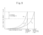
- the engine rotation speed Ne is constant, assuming that the basic injection amount Ti has a characteristic A in Fig. 9 against the intake pressure PM (the initial map axis scale values #PMINDX_N[0] to #PMINDX_N[19]) for a plain, the basic injection amount Ti has a characteristic B in Fig. 9 against the intake pressure PM (the map axis scale values PMINDEX[0] to PMINDEX [19]) for a highland.
- Fig. 9 shows that the value of the basic injection amount Ti of the characteristic A for the plain atmospheric (ATM) pressure at WOT (when the throttle valve is fully open) is the same as the value of the basic injection amount Ti of the characteristic B for the highland atmospheric pressure at WOT.
- the final fuel injection amount Tiout by multiplying the basic injection amount Ti by the correction coefficient MPA as described above, correction is made for the difference in air density.
- the basic injection amount Ti for the highland has a characteristic C in Fig. 9 . Therefore, the final fuel infection amount Tiout can be properly set for the highland as well.
- the present invention is applied to a single cylinder internal combustion engine
- the invention can also be applied to a multi-cylinder internal combustion engine.
- the basic injection amount Ti and the final fuel injection amount Tiout are set by operations, hence reducing the load of the CPU 24 by a greater amount.
- the present invention can be applied to a two dimensional data map where another controlled parameter such as a secondary air amount is determined in accordance with only the intake pressure PM.
- the initial map axis scale values #PMINDX_N[0] to #PMINDX_N[19] multiplied by the high-load map axis correction coefficient MPMIDXH or low-load map axis correction coefficient MPMIDXL in accordance with the detected value of the current atmospheric pressure are set as the scale values PMINOEX[0] to PMINDEX[19] of the Ti-data map, a set of scale values PMINDEX[0] to PMINDEX[19] for each magnitude of the atmospheric pressure may be stored previously, a set of scale values PMINDEX[0] to PMINDEX[19] is selected in accordance with the detected value of the current atmospheric pressure, and the scale values PMINDEX[0] to PMINDEX[19] of the data map may be rewritten with the selected set of scale values.
- the atmospheric pressure PA is detected by the atmospheric pressure sensor 20
- the atmospheric pressure PA may be estimated on the basis of a pressure value detected by a pressure sensor such as the intake pressure sensor 7 or an exhaust pressure sensor (not shown) and used in the map axis correction routine and the fuel injection control routine.
- control apparatus may be configured such that the Ti-data map is formed in the RAM 27 and that the scale values of the Ti-data map are rewritten by correcting for atmospheric pressure.
Abstract
Description
- The present invention relates to a control apparatus for an internal combustion engine such as a fuel injection control apparatus and a control method for the same.
- A basic fuel amount required by an engine for combustion in its cylinder is known to correspond in characteristic to the opening degree of a throttle valve provided in the air-intake manifold and the rotation speed of the engine. Further, because intake pressure that occurs downstream of the throttle valve in the air-intake manifold changes almost proportional to the opening degree of the throttle valve, it is possible to search a data map for the basic fuel amount required by the engine based on the intake pressure and the rotation speed of the engine and to set an amount obtained by the search as the basic fuel amount.
- However, because the intake pressure is influenced by atmospheric pressure, the relationship between the opening degree of the throttle valve and the intake pressure (absolute intake pressure) differs between plains and highlands due to the difference in air density as shown in
Fig. 1 . With the same opening degree of the throttle valve, the intake pressure decreases as the altitude becomes higher. Hence, an appropriate basic fuel amount cannot be set by using the same data map as for plains. Accordingly, when an engine mounted on a vehicle is moved from a plain to a highland, the detected intake pressure value needs to be corrected for high altitude. - In one method of correcting for high altitude, the atmospheric pressure and the intake pressure are detected with use of sensors, a correction coefficient K1 corresponding to the detected value of the atmospheric pressure and a correction coefficient K2 corresponding to the detected value of the intake pressure are calculated, and the detected value of the intake pressure is corrected in accordance with the correction coefficients K1, K2 so that the corrected value of the intake pressure corresponds to an equivalent intake air amount at standard atmospheric pressure at plains (see
Japanese Patent Application Laid-Open Publication No. H05-149187 Japanese Patent Application Laid-Open Publication No. 2003-172172 - Searching a data map based on the intake pressure corrected for high altitude and the rotation speed of the engine to determine the basic fuel amount is usually performed in a conventional fuel injection apparatus.
- However, because the intake pressure always varies depending on the operation state of the engine, correction for high altitude needs to be performed for each time the basic fuel amount is set synchronously with the revolution of the engine. For a four-cycle engine, for each time a crankshaft rotates through at least 720 degrees, the intake amount and the rotation speed of the engine are detected and operations including correction for high altitude are performed. Further, for a multi-cylinder engine, the operations need to be performed for each cylinder. Especially, at high rotation speed, the operation amount per unit time is large, and thus the load of an arithmetic element such as a CPU may become excessive. Accordingly, an expensive arithmetic element having high processing capability needs to be used. This problem occurs in setting the controlled amounts of other controlled parameters that require correction for high altitude such as a secondary air amount of the internal combustion engine, not being limited to the fuel injection amount.
- An object of the present invention is to provide a control apparatus and method for an internal combustion engine, which can reduce the load of an arithmetic element that performs operations for setting a controlled amount in accordance with the detected value of the intake amount.
- A control apparatus for an internal combustion engine according to the present invention comprises: intake pressure detecting means for detecting intake pressure in the internal combustion engine; storage means for storing a data map in which a plurality of scale values for the intake pressure are associated respectively with a plurality of control amounts for a predetermined control parameter of the internal combustion engine; control amount setting means for setting one of the control amounts in the data map corresponding to a detected value of the intake pressure by the intake pressure detecting means as a control amount of the predetermined control parameter; control means for controlling the control parameter of the internal combustion engine in accordance with the control amount set by the control amount setting means; atmospheric pressure detecting means for detecting atmospheric pressure at a place where the internal combustion engine exists; and scale value rewriting means for rewriting each of the plurality of scale values corresponding to the plurality of control amounts in the data map with a value based on a detected value of the atmospheric pressure by the atmospheric pressure detecting means.
- A control method for an internal combustion engine according to the present invention comprises: an intake pressure detecting step of detecting intake pressure in the internal combustion engine; a storage step of storing a data map where a plurality of scale values for the intake pressure are associated respectively with a plurality of control amounts for a predetermined control parameter of the internal combustion engine; a control amount setting step or setting one of the control amounts in the data map corresponding to a detected value of the intake pressure in the intake pressure detecting step as a control amount of the predetermined control parameter; a control step of controlling the control parameter of the internal combustion engine in accordance with the control amount set in the control amount setting step; an atmospheric pressure detecting step of detecting atmospheric pressure at the place where the internal combustion engine exists; and a scale value rewriting step of rewriting each of the plurality of scale values corresponding to the plurality of control amounts in the data map with a value based on a detected value of the atmospheric pressure in the atmospheric pressure detecting step.
- According to the present invention, the data map is stored where the plurality of scale values for the intake pressure are associated respectively with the plurality of control amounts for the predetermined control parameter of the internal combustion engine, and each of the plurality of scale values corresponding to the plurality of control amounts in the data map is rewritten with a value based on a detected value of the atmospheric pressure. When the atmospheric pressure at the place where the internal combustion engine exists changes, each of the plurality of scale values in the data map is rewritten with a value corresponding to the changed atmospheric pressure. Thus, by setting one of the control amounts in the data map corresponding to a detected value of the intake pressure as a control amount of the predetermined control parameter, a control amount which is appropriate for a current atmospheric pressure can be set. Further, since correction for the atmospheric pressure need not be performed for each time a control amount is set, the load of an arithmetic element used in the control means can be reduced.
-
-
Fig. 1 is a diagram showing intake pressure against the opening degree of a throttle valve for a plain and a highland; -
Fig. 2 shows an engine control system to which the present invention is applied; -
Fig. 3 is a block diagram showing a specific configuration of the ECU ofFig.2 ; -
Fig. 4 shows a Ti-data map formed in ROM; -
Fig. 5 shows corrected map axis scale values PMINDEX [Index] stored in RAM; -
Fig. 6 is a flow chart showing operation according to a map axis correction routine; -
Fig. 7 shows corrected map axis scale values PMINDXB [Index] stored in RAM; -
Fig. 8 is a flow chart showing operation according to a fuel injection control routine; and -
Fig. 9 shows characteristics of a basic injection amount against intake pressure for a plain and a highland and a characteristic of the basic injection amount after air density correction. - An embodiment according to the present invention will be described in detail below with reference to the drawings.
-
Fig. 2 shows an engine control system for a four-cycle internal combustion engine to which the present invention is applied. In the internal combustion engine, athrottle valve 3 is provided in anintake manifold 2 coupled to the intake port of anengine body 1. Air taken in through anair cleaner 4 is supplied by an amount corresponding to the opening degree of thethrottle valve 3 to the intake port of theengine body 1 through theintake manifold 2. Athrottle sensor 5 is provided for thethrottle valve 3 and detects the opening degree of thethrottle valve 3. An injector (fuel injection valve) 6 is provided in theintake manifold 2 near the intake port of theengine body 1. A fuel pump sends fuel from a fuel tank (not shown) to theinjector 6 by pressure. Theintake manifold 2 is provided with anintake pressure sensor 7 and anintake temperature sensor 8. Theintake pressure sensor 7 detects taken-in air pressure, i.e. intake pressure, in theintake manifold 2. Theintake temperature sensor 8 detects a temperature of the taken-in air in theintake manifold 2. - A
catalyst 11 and anoxygen concentration sensor 12 are provided in anexhaust manifold 10 coupled to the exhaust port of theengine body 1. Thecatalyst 11 reduces unburned components in exhaust gas in theexhaust manifold 10. Theoxygen concentration sensor 12 detects an oxygen concentration in the exhaust gas. - An
ignition plug 13 is fixed to theengine body 1 and connected to anigniting device 14. An ECU (electronic control unit) 15 described later issues an ignition timing instruction to theigniting device 14, thereby causing spark discharge to occur in the cylinder combustion chamber of theengine body 1. - A
cooling water passage 16a is formed in acylinder block 16 forming theengine body 1. A coolingwater temperature sensor 17 is provided in thecylinder block 16 and detects a temperature of cooling water in thecooling water passage 16a. - The outputs of the
throttle sensor 5, theintake pressure sensor 7, theintake temperature sensor 8, theoxygen concentration sensor 12, and the coolingwater temperature sensor 17 are connected to theECU 15. Also, acrank angle sensor 19 and anatmospheric pressure sensor 20 which detects atmospheric pressure are connected to theECU 15. Thecrank angle sensor 19 is provided for detecting a rotation angle position of acrankshaft 18 of theengine body 1. In thecrank angle sensor 19, a plurality of protrusions are provided at predetermined angular intervals (e.g., 15 degrees) on the periphery of arotor 19a rotating in association with thecrankshaft 18, and apickup 19b placed near the periphery of therotor 19a magnetically or optically detects each of the protrusions. When one of the protrusions passes by thepickup 19b by rotation of therotor 19a as well as thecrankshaft 18, thepickup 19b generate a pulse (crank signal). The pulse is generated for each time thecrankshaft 18 rotates through a predetermined angle. Thecrank angle sensor 19 outputs a signal indicating a reference angle to a CPU (central processing unit) 24, described later, in theECU 15 for each time apiston 9 reaches the position of top dead center ; (TDC) or thecrankshaft 18 rotates through 360 degrees. - The
throttle sensor 5, theintake pressure sensor 7, theintake temperature sensor 8, theoxygen concentration sensor 12, the coolingwater temperature sensor 17, and theatmospheric pressure sensor 20 each output an analog voltage corresponding to their detected value. - Also, the
injector 6 andigniting device 14 mentioned above are connected to theECU 15. - As shown in
Fig. 3 , theECU 15 comprises awaveform shaping circuit 21, acounter 22, an A/D converter 23, aCPU 24, adrive circuit 25, ROM (read only memory) 26, RAM (random access memory) 27, and atimer 28. - The
waveform shaping circuit 21 shapes a pulse output from thecrank angle sensor 19 into a rectangular pulse, for example and outputs the shaped pulse to thecounter 22. The counter 22 counts pulses output from thewaveform shaping circuit 21 and outputs data indicating the number of pulses per predetermined time to theCPU 24, which obtains engine rotation speed Ne from the number of pulses per predetermined time. - The A/
D converter 23 converts the analog voltages output from each of thethrottle sensor 5, theintake pressure sensor 7, theintake temperature sensor 8, theoxygen concentration sensor 12, the coolingwater temperature sensor 17, and theatmospheric pressure sensor 20, and the output voltage of a battery 30 into digital signals respectively and holds these signals. The digital signals are supplied to theCPU 24. TheCPU 24 can read the opening degree qth of thethrottle valve 3, intake pressure PM, intake temperature TA, oxygen concentration 02, cooling water temperature TW, atmospheric pressure PA, and battery voltage VB from the A/D converter 23 as well as the engine rotation speed Ne as detected values of engine parameters. Further, theCPU 24 detects the rotation angle position at predetermined angular intervals of thecrankshaft 18 based on the signal indicating the reference angle of the crank angle from thecrank angle sensor 19 and the output pulses of thewaveform shaping circuit 21. TheCPU 24 performs fuel injection control and ignition time control in accordance with the detected values of the engine parameters and the rotation angle position at predetermined angular intervals of thecrankshaft 18. - The
drive circuit 25 drives theinjector 6 in accordance with a fuel injection instruction from theCPU 24 in the fuel injection control and drives the ignitingdevice 14 in accordance with an energizing-ignition instruction from theCPU 24 in the ignition time control. - Programs and data such as a data map for the fuel injection control and the ignition time control by the
CPU 24 are previously written in theROM 26. Data such as the detected values of the engine parameters and computed values including a fuel injection amount are written into theRAM 27 in the fuel injection control and the ignition time control by theCPU 24. - As a specific example, in the
ROM 26, a Ti-data map is formed in a table format as shown inFig. 4 to calculate a basic injection amount Ti in accordance with the intake pressure PM and the engine rotation speed Ne for the fuel injection control. In the Figure, #PMINDX_N[0] to #PMINDX_N[19] indicate initial map axis scale values that are major values of the intake pressure PM, and #NEINDX_N[0] to #NEINDX_N[a] indicate map axis scale values that are major values of the engine rotation speed Ne. #TI[0, 0] to # TI[a, 19] indicate basic injection amounts Ti determined by the map axis scale values of the intake pressure PM and of the engine rotation speed Ne. As shown inFig. 5 , theRAM 27 has an area where the map axis scale values of #PMINDX_N[0] to #PMINDX_N[19] after correction are stored as PMINDEX[0] to PMINDEX[19]. The PMINDEX[0] to PMINDEX[19] are associated by numbers in the square brackets with the #PMINDX_N[0] to #PMINDX_N[19] respectively. - The
timer 28 is also used by theCPU 24 to measure time points to issue the fuel injection instruction and the energizing-ignition instruction, but in this embodiment, only thetimer 28 operating as an injector valve opening timer is shown. - In the engine control system of the configuration as described above, the
CPU 24 executes a fuel injection control routine in interrupt processing synchronously with the rotation of the engine, for example, at a predetermined crank angle while executing a map axis correction routine, for example, in background processing at a predetermined cycle independently of the rotation of the engine. - In the map axis correction routine, as shown in
Fig. 6 , theCPU 24 reads a current atmospheric pressure PA from the A/D converter 23(step S0) and sets a correction coefficient MPA for the fuel injection control in accordance with the read atmospheric pressure PA (step S1). Then, theCPU 24 sets a map axis correction coefficient MPMIDXH for a high load in accordance with the atmospheric pressure PA (step S2) and sets a map axis correction coefficient MPMIDXL for a low load in accordance with the atmospheric pressure PA (step 33). These correction coefficients MPA, MPMIDXH, and MPMIDXL are decided uniquely using data maps (not shown). - The CPU 29 places the content of a flag F_RENEWIDX into a flag F_REIDXINH (step S4) and resets the flag F_RENEWIDX to zero (step S5). The flag F_RENEWIDX is used to indicate that a map axis update has occurred.
- The
CPU 24 sets a variable Index to zero (step S6) and determines whether the Index is greater than the maximum value of a low-load INDEX (step 37). The Index indicates the number of scale values for the intake air amount in the Ti-data map, e.g., a value of 0 to 19. The maximum value of the low-load INDEX is a threshold value for distinguishing a low load area and a high load area in the Ti-data map. If the Index ≤ the maximum value of the low-load INDEX, because of being in the low load area, the initial map axis scale value #PMINDX_N [Index] multiplied by the low-load map axis correction coefficient MPMIDXL is set as a corrected map axis scale value PMINDXB[Index] (step S8). On the other hand, if the Index> the maximum value of the low-load INDEX, because of being in the high load area, the initial map axis scale value #PMINDX_N[Index] multiplied by the high-load map axis correction coefficient MPMIDXH is set as the corrected map axis scale value PMINDXB[Index] (step S9). The initial map axis scale value #PMINDX_N[Index] is previously recorded in theROM 26 as mentioned above. The corrected map axis scale value PMINDXB[Index] is stored into theRAM 27 for Index = 0 to 19, e.g., where PMINDXB[0] to PMINDXB[19] will be formed as shown inFig. 7 . - After the execution of step S8 or S9, the Index is incremented by 1 (step S10), and it is determined whether the Index is greater than the maximum value of a high-load INDEX (step S11). The maximum value of the high-load INDEX is the upper limit, e.g. 19, of the high load area in the Ti-data map. If the Index ≤ the maximum value of the high-load INDEX, the process returns to step S7 and performs the operation of setting as the corrected map axis scale value PMINDXB[Index]. If the Index > the maximum value of the high-load INDEX, all the corrected map axis scale values PMINDXB[Index] have been stored into the
RAM 27. - The
CPU 24 determines whether the previous atmospheric pressure PAPRE is equal to the current atmospheric pressure PA (step S12). The previous atmospheric pressure PAPRE is the atmospheric pressure PA at the previous execution of the map axis correction routine. If PAPRE=PA, because the current atmospheric pressure PA does not differ from the atmospheric pressure PAPRE at the previous execution of the map axis correction routine, the flag F_RENEWIDX is set to the content of the flag F_REIDXINH (step S13). On the other hand, if PAPRE ≠ PA, because the current atmospheric pressure PA differs from the atmospheric pressure PAPRE at the previous execution of the map axis correction routine, the flag F_REMEWIDX is set to 1 (step S14). Note that at step S12, PAPRE and PA are determined as equal when their difference is within a permissible range of ±ΔPA. - The
CPU 24 determines whether the engine is stopped (step S15). For example, when the engine rotation speed Ne is at or below a predetermined rotation speed, it is determined that the engine is stopped. If the engine is stopped, it is determined whether the flag F_RENEWIDX is at 1 (step S16). If the flag F_REFIEWIDX = 1, because it indicates that the current atmospheric pressure PA differs from the atmospheric pressure PAPRE at the previous execution of the map axis correction routine as mentioned above, the flag F_RENEWIDX is reset to zero (step S17) and the Index is set to zero (step S18), and the corrected map axis scale value PMINDXB[Index] is stored into the map axis scale value PMINDEX[Index] (step S19). The map axis scale value PMINDEX[Index] is overwritten into the RAM27. After the execution of step S19, the Index is incremented by 1 (step S20), and it is determined whether the Index is greater than the maximum value of the high-load INDEX (step S21). If the Index ≤ the maximum value of the high-load INDEX, the process returns to step S19, which stores the corrected map axis scale value PMINDXB[Index] into the map axis scale value PMINDEX[Index] . If the Index > the maximum value of the high-load INDEX, because it indicates that all the map axis scale values PMINDEX[Index] have been stored into theRAM 27, the current atmospheric pressure PA is stored as the previous atmospheric pressure PAPRE (step S22). - If the
CPU 24 determines at step S15 that the engine is not stopped or at step S16 that the flag F_RENEWIDX = 0, the process proceeds to step S22, where the current atmospheric pressure PA is stored as the previous atmospheric pressure PAPRE. - In the map axis correction routine, interrupt processing is prohibited during the execution of steps S4, S5 and S16 to S21.
- In the fuel injection control routine, as shown in
Fig. 8 , theCPU 24 reads a current intake pressure PM from the A/D converter 23 (step S31) and obtains a current engine rotation speed Ne from the output of the counter 22 (step S32), and then determines whether the flag F_RENENIDX is at 1 (step S33). If the F_RENENIDX = 1, because it indicates that the current atmospheric pressure PA differs from the atmospheric pressure PAPRE at the previous execution of the map axis correction routine, the flag F_RENEMIDX is reset to zero (step S34) and the Index is set to zero (step S35), and the corrected map axis scale value PMINDXB[Index] is overwritten into the map axis scale value PMINDEX[Index] (step S36). After the execution of step S36, the Index is incremented by 1 (step S37), and it is determined whether the Index is greater than the maximum value of the high-load INDEX (step S38). If the Index ≤ the maximum value of the high-load INDEX, the process returns to step S36, which stores the corrected map axis scale value PMINOXB [Index] into the PMINOEX [Index]. The operation of these steps S33 to S38 is the same as that of steps S16 to S21 previously described. - If determining that the F_RENEWIDX = 0 at step S33 or that the Index > the maximum value of the high-load INDEX at step S38, the
CPU 24 immediately executes steps S39 and S40. At step S39, theCPU 24 searches the Ti-data map in theROM 26 for the basic injection amount Ti corresponding to the current intake pressure PM and the current engine rotation speed Ne with use of the map axis scale values PMINDEX [Index] in theRAM 27 and sets an amount obtained by the search as the basic injection amount Ti. If the current intake pressure PM is an intermediate value between the map axis scale values PHINDEX [0] to PMINDEX [19], or if the current engine rotation speed Ne is an intermediate value between the map axis scale values #NEINDX_N[0] to #NEINDX_N[a], an interpolation is used to set the basic injection amount Ti. At step S40, the basic injection amount Ti is corrected with a fuel correction coefficient corresponding to various engine parameters and corrected for injector invalid time, and the corrected amount is set as a final fuel injection amount Tiout. - The fuel correction coefficient is based on various correction coefficients as well as the atmospheric pressure correction coefficient MPA. For example, an oxygen concentration O2 is read, a current air-fuel ratio A/F corresponding to the oxygen concentration 02 is obtained from an A/F data map in the
ROM 26, and a feedback correction coefficient MHG is calculated which depends on the difference between the current air-fuel ratio A/F and a target air-fuel ratio (e.g., 14.7). Further, a cooling water temperature TM is read, a TW data map in theROM 26 is searched for a water temperature correction coefficient MTN corresponding to the cooling water temperature TW. Yet further, an intake temperature TA is read, a TA data map in theROM 26 is searched for an intake temperature correction coefficient MTA corresponding to the intake temperature TA. By multiplying these correction coefficients MPA, MTN, MTA, ... , the fuel correction coefficient is obtained. By multiplying the basic injection amount Ti by the fuel correction coefficient and adding injector invalid time thereto, the final fuel injection amount Tiout (a final control amount) is obtained. The final fuel injection amount Tiout indicates a time width of fuel injection by theinjector 6. By the multiplying of the correction coefficient MPA, air density correction is performed. - After the calculation of the final fuel injection amount Tiout, the
CPU 24 sets the final fuel injection amount Tiout in the injector valve opening timer at fuel injection start timing and has the timer start measuring time, so that only during the time when the injector valve opening timer is measuring time for the final fuel injection amount Tiout, theinjector 6 is driven by thedrive circuit 25 to inject fuel. - By the operations according to the map axis correction routine and the fuel injection control routine, the map axis scale values PMINDEX [Index] of the Ti-data map are updated when the atmospheric pressure PA changes. Where the engine rotation speed Ne is constant, assuming that the basic injection amount Ti has a characteristic A in
Fig. 9 against the intake pressure PM (the initial map axis scale values #PMINDX_N[0] to #PMINDX_N[19]) for a plain, the basic injection amount Ti has a characteristic B inFig. 9 against the intake pressure PM (the map axis scale values PMINDEX[0] to PMINDEX [19]) for a highland. That is, because the characteristic B is a characteristic into which the characteristic A has been pressed in a direction parallel to the intake pressure axis, the basic injection amount Ti is prevented from being set to be smaller due to the intake pressure being lower on the highland.Fig. 9 shows that the value of the basic injection amount Ti of the characteristic A for the plain atmospheric (ATM) pressure at WOT (when the throttle valve is fully open) is the same as the value of the basic injection amount Ti of the characteristic B for the highland atmospheric pressure at WOT. Moreover, in calculating the final fuel injection amount Tiout, by multiplying the basic injection amount Ti by the correction coefficient MPA as described above, correction is made for the difference in air density. Thus, the basic injection amount Ti for the highland has a characteristic C inFig. 9 . Therefore, the final fuel infection amount Tiout can be properly set for the highland as well. - Since the atmospheric pressure PA does not change suddenly or frequently, the number of times the map axis scale values PMINDEX[Index] are actually updated is small. Therefore, the operation of correcting for the atmospheric pressure for each time the intake pressure PM is detected to set the basic injection amount Ti synchronously with the rotation of the engine need not be performed like in the prior art, thus reducing the load of the
CPU 24. - Although in the above embodiment the present invention is applied to a single cylinder internal combustion engine, the invention can also be applied to a multi-cylinder internal combustion engine. In the multi-cylinder internal combustion engine, for each cylinder, the basic injection amount Ti and the final fuel injection amount Tiout are set by operations, hence reducing the load of the
CPU 24 by a greater amount. - Although in the above embodiment a three dimensional data map is described where the basic injection amount. Ti is determined in accordance with the intake pressure PM and the engine rotation speed Ne, the present invention can be applied to a two dimensional data map where another controlled parameter such as a secondary air amount is determined in accordance with only the intake pressure PM.
- Although in the above embodiment the initial map axis scale values #PMINDX_N[0] to #PMINDX_N[19] multiplied by the high-load map axis correction coefficient MPMIDXH or low-load map axis correction coefficient MPMIDXL in accordance with the detected value of the current atmospheric pressure are set as the scale values PMINOEX[0] to PMINDEX[19] of the Ti-data map, a set of scale values PMINDEX[0] to PMINDEX[19] for each magnitude of the atmospheric pressure may be stored previously, a set of scale values PMINDEX[0] to PMINDEX[19] is selected in accordance with the detected value of the current atmospheric pressure, and the scale values PMINDEX[0] to PMINDEX[19] of the data map may be rewritten with the selected set of scale values.
- Although in the above embodiment the atmospheric pressure PA is detected by the
atmospheric pressure sensor 20, the atmospheric pressure PA may be estimated on the basis of a pressure value detected by a pressure sensor such as theintake pressure sensor 7 or an exhaust pressure sensor (not shown) and used in the map axis correction routine and the fuel injection control routine. - Although in the above embodiment the Ti-data map is formed in the
ROM 26, the control apparatus may be configured such that the Ti-data map is formed in theRAM 27 and that the scale values of the Ti-data map are rewritten by correcting for atmospheric pressure.
Claims (6)
- A control apparatus for an internal combustion engine, comprising:intake pressure detecting means for detecting intake pressure in said internal combustion engine;storage means for storing a data map in which a plurality of scale values for the intake pressure are associated respectively with a plurality of control amounts for a predetermined control parameter of said internal combustion engine;control amount setting means for setting one of the control amounts in the data map corresponding to a detected value of the intake pressure by said intake pressure detecting means as a control amount of the predetermined control parameter;control means for controlling the control parameter of said internal combustion engine in accordance with the control amount set by said control amount setting means;atmospheric pressure detecting means for detecting atmospheric pressure at a place where said internal combustion engine exists; andscale value rewriting means for rewriting each of the plurality of scale values corresponding to the plurality of control amounts in the data map with a value based on a detected value of the atmospheric pressure by said atmospheric pressure detecting means.
- The control apparatus according to claim 1, wherein the predetermined control parameter is the amount of fuel to be injected into said internal combustion engine by an injector, and in the data map which has a plurality of scale values for the intake pressure and a plurality of fixed scale values for engine rotation speed of said internal combustion engine, a pair of scale values which is formed by each of the plurality of scale values for the intake pressure and each of the plurality of fixed scale values for the engine rotation speed is associated with each of a plurality of control amounts for the amount of fuel.
- The control apparatus according to claim 1, wherein when a detected value of the atmospheric pressure by said atmospheric pressure detecting means is changed, said scale value rewriting means rewrites each of the plurality of scale values corresponding to the plurality of control amounts in the data map with a value based on to a current detected value of the atmospheric pressure by said atmospheric pressure detecting means.
- The control apparatus according to claim 1, further comprising:means for setting an atmospheric pressure correction efficient in accordance with the detected value of the atmospheric pressure by said atmospheric pressure detecting means; andfinal control amount calculating means for calculating a final control amount by correcting the control amount set by said control amount setting means in accordance with the atmospheric pressure correction efficient,wherein said control means controls the control parameter of said internal combustion engine in accordance with the final control amount.
- The control apparatus according to claim 1, wherein said storage means includes:a read only memory for storing the data map with the plurality of scale values being initial values; anda random access memory for storing a rewritten value for each of the plurality of scale values, andwherein said scale value rewriting means includes:means for setting a map axis correction efficient in accordance with the detected value of the atmospheric pressure by said atmospheric pressure detecting means;multiplying means for multiplying the initial value of each of the plurality of scale values by the map axis correction efficient; andmeans for writing into said random access memory resulting values of the multiplication by said multiplying means as the plurality of scale values corresponding to the plurality of control amounts so as to correspond respectively to the initial values of the data map in said read only memory.
- A control method for an internal combustion engine, comprising:an intake pressure detecting step of detecting intake pressure in said internal combustion engine;a storage step of storing a data map where a plurality of scale values for the intake pressure are associated respectively with a plurality of control amounts for a predetermined control parameter of said internal combustion engine;a control amount setting step of setting one of the control amounts in the data map corresponding to a detected value of the intake pressure in the intake pressure detecting step as a control amount of the predetermined control parameter;a control step of controlling the control parameter of said internal combustion engine in accordance with the control amount set in the control amount setting step;an atmospheric pressure detecting step of detecting atmospheric pressure at the place where said internal combustion engine exists; anda scale value rewriting step of rewriting each of the plurality of scale values corresponding to the plurality of control amounts in the data map with a value based on a detected value of the atmospheric pressure in the atmospheric pressure detecting step.
Applications Claiming Priority (1)
| Application Number | Priority Date | Filing Date | Title |
|---|---|---|---|
| JP2006331988A JP4827710B2 (en) | 2006-12-08 | 2006-12-08 | Control device and method for internal combustion engine |
Publications (3)
| Publication Number | Publication Date |
|---|---|
| EP1930576A2 true EP1930576A2 (en) | 2008-06-11 |
| EP1930576A3 EP1930576A3 (en) | 2011-04-13 |
| EP1930576B1 EP1930576B1 (en) | 2013-07-03 |
Family
ID=39083244
Family Applications (1)
| Application Number | Title | Priority Date | Filing Date |
|---|---|---|---|
| EP20070122156 Active EP1930576B1 (en) | 2006-12-08 | 2007-12-03 | Control Apparatus and Method for Internal Combustion Engine |
Country Status (2)
| Country | Link |
|---|---|
| EP (1) | EP1930576B1 (en) |
| JP (1) | JP4827710B2 (en) |
Families Citing this family (2)
| Publication number | Priority date | Publication date | Assignee | Title |
|---|---|---|---|---|
| JP6267880B2 (en) * | 2013-06-28 | 2018-01-24 | 株式会社ケーヒン | Vehicle electronic control unit rewriting device, vehicle electronic control unit rewriting program, and vehicle electronic control unit |
| JP7359367B2 (en) | 2019-07-17 | 2023-10-11 | 株式会社トランストロン | Engine intake system control device and its control method |
Citations (2)
| Publication number | Priority date | Publication date | Assignee | Title |
|---|---|---|---|---|
| JPH05149187A (en) | 1991-11-25 | 1993-06-15 | Daihatsu Motor Co Ltd | Atmospheric pressure correction method for engine |
| JP2003172172A (en) | 2001-09-28 | 2003-06-20 | Denso Corp | Controller for internal combustion engine |
Family Cites Families (7)
| Publication number | Priority date | Publication date | Assignee | Title |
|---|---|---|---|---|
| JPH0833130B2 (en) * | 1987-02-25 | 1996-03-29 | 株式会社ユニシアジェックス | Learning control device for air-fuel ratio of internal combustion engine |
| JP2535935B2 (en) * | 1987-08-11 | 1996-09-18 | トヨタ自動車株式会社 | Fuel injection method for internal combustion engine |
| JPH0261346A (en) * | 1988-08-25 | 1990-03-01 | Japan Electron Control Syst Co Ltd | Fuel supply controller for internal combustion engine |
| JPH08200191A (en) * | 1995-01-18 | 1996-08-06 | Toyota Motor Corp | Ignition timing control device for internal combustion engine |
| JP3663668B2 (en) * | 1995-04-28 | 2005-06-22 | いすゞ自動車株式会社 | Electronically controlled fuel injection apparatus and method |
| JP3838526B2 (en) * | 1997-04-10 | 2006-10-25 | 株式会社デンソー | Fuel injection control device and fuel injection control method for internal combustion engine |
| JP2008045506A (en) * | 2006-08-18 | 2008-02-28 | Nikki Co Ltd | Atmospheric pressure correction method in engine control and its control device |
-
2006
- 2006-12-08 JP JP2006331988A patent/JP4827710B2/en not_active Expired - Fee Related
-
2007
- 2007-12-03 EP EP20070122156 patent/EP1930576B1/en active Active
Patent Citations (2)
| Publication number | Priority date | Publication date | Assignee | Title |
|---|---|---|---|---|
| JPH05149187A (en) | 1991-11-25 | 1993-06-15 | Daihatsu Motor Co Ltd | Atmospheric pressure correction method for engine |
| JP2003172172A (en) | 2001-09-28 | 2003-06-20 | Denso Corp | Controller for internal combustion engine |
Also Published As
| Publication number | Publication date |
|---|---|
| JP2008144655A (en) | 2008-06-26 |
| JP4827710B2 (en) | 2011-11-30 |
| EP1930576B1 (en) | 2013-07-03 |
| EP1930576A3 (en) | 2011-04-13 |
Similar Documents
| Publication | Publication Date | Title |
|---|---|---|
| JP2510250B2 (en) | Combustion control device for internal combustion engine | |
| JPS6060019B2 (en) | How to control the engine | |
| JP2835676B2 (en) | Air-fuel ratio control device for internal combustion engine | |
| US5016595A (en) | Air-fuel ratio control device for internal combustion engine | |
| JPS6256342B2 (en) | ||
| JP4027892B2 (en) | Engine control device | |
| EP1930576B1 (en) | Control Apparatus and Method for Internal Combustion Engine | |
| US4697568A (en) | Fuel injection timing control method for internal combustion engines | |
| JP2843872B2 (en) | Engine load parameter calculation device and engine control device | |
| JPH081142B2 (en) | Engine air-fuel ratio control device | |
| JPH0410360Y2 (en) | ||
| JP4243383B2 (en) | Fuel evaporation characteristic detection device and control device for internal combustion engine | |
| JPH0742892B2 (en) | Intake air amount detector | |
| JP2712153B2 (en) | Load detection device for internal combustion engine | |
| JP2586435B2 (en) | Knocking control device for internal combustion engine | |
| JP2914973B2 (en) | Electronic engine control unit | |
| JPS58185945A (en) | Air-fuel ratio controller for internal-combustion engine | |
| JP2760154B2 (en) | Fuel injection amount control device | |
| JP2996444B2 (en) | Control device for internal combustion engine | |
| JP2750777B2 (en) | Electronic control fuel supply device for internal combustion engine | |
| JPH05321726A (en) | Control device for internal combustion engine | |
| JPH0281942A (en) | Combustion control device for internal combustion engine | |
| JP2636298B2 (en) | Air-fuel ratio control device for multi-cylinder internal combustion engine | |
| JP2514442B2 (en) | Knock detection device for internal combustion engine | |
| JPS6165037A (en) | Air-fuel ratio control system for internal-combustion engine |
Legal Events
| Date | Code | Title | Description |
|---|---|---|---|
| PUAI | Public reference made under article 153(3) epc to a published international application that has entered the european phase |
Free format text: ORIGINAL CODE: 0009012 |
|
| AK | Designated contracting states |
Kind code of ref document: A2 Designated state(s): AT BE BG CH CY CZ DE DK EE ES FI FR GB GR HU IE IS IT LI LT LU LV MC MT NL PL PT RO SE SI SK TR |
|
| AX | Request for extension of the european patent |
Extension state: AL BA HR MK RS |
|
| PUAL | Search report despatched |
Free format text: ORIGINAL CODE: 0009013 |
|
| AK | Designated contracting states |
Kind code of ref document: A3 Designated state(s): AT BE BG CH CY CZ DE DK EE ES FI FR GB GR HU IE IS IT LI LT LU LV MC MT NL PL PT RO SE SI SK TR |
|
| AX | Request for extension of the european patent |
Extension state: AL BA HR MK RS |
|
| 17P | Request for examination filed |
Effective date: 20110930 |
|
| AKX | Designation fees paid |
Designated state(s): DE GB IT |
|
| GRAP | Despatch of communication of intention to grant a patent |
Free format text: ORIGINAL CODE: EPIDOSNIGR1 |
|
| GRAS | Grant fee paid |
Free format text: ORIGINAL CODE: EPIDOSNIGR3 |
|
| GRAA | (expected) grant |
Free format text: ORIGINAL CODE: 0009210 |
|
| AK | Designated contracting states |
Kind code of ref document: B1 Designated state(s): DE GB IT |
|
| REG | Reference to a national code |
Ref country code: GB Ref legal event code: FG4D |
|
| REG | Reference to a national code |
Ref country code: DE Ref legal event code: R096 Ref document number: 602007031364 Country of ref document: DE Effective date: 20130829 |
|
| PLBE | No opposition filed within time limit |
Free format text: ORIGINAL CODE: 0009261 |
|
| STAA | Information on the status of an ep patent application or granted ep patent |
Free format text: STATUS: NO OPPOSITION FILED WITHIN TIME LIMIT |
|
| 26N | No opposition filed |
Effective date: 20140404 |
|
| REG | Reference to a national code |
Ref country code: DE Ref legal event code: R097 Ref document number: 602007031364 Country of ref document: DE Effective date: 20140404 |
|
| REG | Reference to a national code |
Ref country code: DE Ref legal event code: R082 Ref document number: 602007031364 Country of ref document: DE Representative=s name: STAUDT IP LAW, DE |
|
| REG | Reference to a national code |
Ref country code: GB Ref legal event code: 732E Free format text: REGISTERED BETWEEN 20211210 AND 20211215 |
|
| REG | Reference to a national code |
Ref country code: DE Ref legal event code: R081 Ref document number: 602007031364 Country of ref document: DE Owner name: HITACHI ASTEMO, LTD., HITACHINAKA-SHI, JP Free format text: FORMER OWNER: KEIHIN CORPORATION, TOKYO, JP |
|
| PGFP | Annual fee paid to national office [announced via postgrant information from national office to epo] |
Ref country code: IT Payment date: 20221111 Year of fee payment: 16 Ref country code: GB Payment date: 20221027 Year of fee payment: 16 Ref country code: DE Payment date: 20221102 Year of fee payment: 16 |
|
| REG | Reference to a national code |
Ref country code: DE Ref legal event code: R082 Ref document number: 602007031364 Country of ref document: DE Representative=s name: SONNENBERG HARRISON PARTNERSCHAFT MBB PATENT- , DE |