EP1429469A2 - CDMA-Empfänger für Mehrwegausbreitung und reduziertes Pilotsignal - Google Patents
CDMA-Empfänger für Mehrwegausbreitung und reduziertes Pilotsignal Download PDFInfo
- Publication number
- EP1429469A2 EP1429469A2 EP04006118A EP04006118A EP1429469A2 EP 1429469 A2 EP1429469 A2 EP 1429469A2 EP 04006118 A EP04006118 A EP 04006118A EP 04006118 A EP04006118 A EP 04006118A EP 1429469 A2 EP1429469 A2 EP 1429469A2
- Authority
- EP
- European Patent Office
- Prior art keywords
- signal
- channel
- despread
- pilot
- produce
- Prior art date
- Legal status (The legal status is an assumption and is not a legal conclusion. Google has not performed a legal analysis and makes no representation as to the accuracy of the status listed.)
- Withdrawn
Links
Images


Classifications
-
- H—ELECTRICITY
- H04—ELECTRIC COMMUNICATION TECHNIQUE
- H04B—TRANSMISSION
- H04B1/00—Details of transmission systems, not covered by a single one of groups H04B3/00 - H04B13/00; Details of transmission systems not characterised by the medium used for transmission
- H04B1/69—Spread spectrum techniques
- H04B1/707—Spread spectrum techniques using direct sequence modulation
- H04B1/7073—Synchronisation aspects
- H04B1/7085—Synchronisation aspects using a code tracking loop, e.g. a delay-locked loop
-
- H—ELECTRICITY
- H04—ELECTRIC COMMUNICATION TECHNIQUE
- H04B—TRANSMISSION
- H04B1/00—Details of transmission systems, not covered by a single one of groups H04B3/00 - H04B13/00; Details of transmission systems not characterised by the medium used for transmission
- H04B1/06—Receivers
- H04B1/16—Circuits
- H04B1/30—Circuits for homodyne or synchrodyne receivers
-
- H—ELECTRICITY
- H04—ELECTRIC COMMUNICATION TECHNIQUE
- H04B—TRANSMISSION
- H04B1/00—Details of transmission systems, not covered by a single one of groups H04B3/00 - H04B13/00; Details of transmission systems not characterised by the medium used for transmission
- H04B1/69—Spread spectrum techniques
- H04B1/707—Spread spectrum techniques using direct sequence modulation
- H04B1/7073—Synchronisation aspects
- H04B1/7075—Synchronisation aspects with code phase acquisition
- H04B1/70755—Setting of lock conditions, e.g. threshold
-
- H—ELECTRICITY
- H04—ELECTRIC COMMUNICATION TECHNIQUE
- H04B—TRANSMISSION
- H04B1/00—Details of transmission systems, not covered by a single one of groups H04B3/00 - H04B13/00; Details of transmission systems not characterised by the medium used for transmission
- H04B1/69—Spread spectrum techniques
- H04B1/707—Spread spectrum techniques using direct sequence modulation
- H04B1/709—Correlator structure
- H04B1/7093—Matched filter type
-
- H—ELECTRICITY
- H04—ELECTRIC COMMUNICATION TECHNIQUE
- H04L—TRANSMISSION OF DIGITAL INFORMATION, e.g. TELEGRAPHIC COMMUNICATION
- H04L27/00—Modulated-carrier systems
- H04L27/0014—Carrier regulation
-
- H—ELECTRICITY
- H04—ELECTRIC COMMUNICATION TECHNIQUE
- H04B—TRANSMISSION
- H04B1/00—Details of transmission systems, not covered by a single one of groups H04B3/00 - H04B13/00; Details of transmission systems not characterised by the medium used for transmission
- H04B1/69—Spread spectrum techniques
- H04B1/707—Spread spectrum techniques using direct sequence modulation
- H04B1/7097—Interference-related aspects
- H04B1/711—Interference-related aspects the interference being multi-path interference
- H04B1/7115—Constructive combining of multi-path signals, i.e. RAKE receivers
-
- H—ELECTRICITY
- H04—ELECTRIC COMMUNICATION TECHNIQUE
- H04B—TRANSMISSION
- H04B2201/00—Indexing scheme relating to details of transmission systems not covered by a single group of H04B3/00 - H04B13/00
- H04B2201/69—Orthogonal indexing scheme relating to spread spectrum techniques in general
- H04B2201/707—Orthogonal indexing scheme relating to spread spectrum techniques in general relating to direct sequence modulation
- H04B2201/70701—Orthogonal indexing scheme relating to spread spectrum techniques in general relating to direct sequence modulation featuring pilot assisted reception
-
- H—ELECTRICITY
- H04—ELECTRIC COMMUNICATION TECHNIQUE
- H04L—TRANSMISSION OF DIGITAL INFORMATION, e.g. TELEGRAPHIC COMMUNICATION
- H04L27/00—Modulated-carrier systems
- H04L27/0014—Carrier regulation
- H04L2027/0044—Control loops for carrier regulation
- H04L2027/0063—Elements of loops
- H04L2027/0067—Phase error detectors
-
- H—ELECTRICITY
- H04—ELECTRIC COMMUNICATION TECHNIQUE
- H04L—TRANSMISSION OF DIGITAL INFORMATION, e.g. TELEGRAPHIC COMMUNICATION
- H04L25/00—Baseband systems
- H04L25/02—Details ; arrangements for supplying electrical power along data transmission lines
- H04L25/0202—Channel estimation
- H04L25/0212—Channel estimation of impulse response
-
- Y—GENERAL TAGGING OF NEW TECHNOLOGICAL DEVELOPMENTS; GENERAL TAGGING OF CROSS-SECTIONAL TECHNOLOGIES SPANNING OVER SEVERAL SECTIONS OF THE IPC; TECHNICAL SUBJECTS COVERED BY FORMER USPC CROSS-REFERENCE ART COLLECTIONS [XRACs] AND DIGESTS
- Y02—TECHNOLOGIES OR APPLICATIONS FOR MITIGATION OR ADAPTATION AGAINST CLIMATE CHANGE
- Y02D—CLIMATE CHANGE MITIGATION TECHNOLOGIES IN INFORMATION AND COMMUNICATION TECHNOLOGIES [ICT], I.E. INFORMATION AND COMMUNICATION TECHNOLOGIES AIMING AT THE REDUCTION OF THEIR OWN ENERGY USE
- Y02D30/00—Reducing energy consumption in communication networks
- Y02D30/70—Reducing energy consumption in communication networks in wireless communication networks
Definitions
- the present invention relates generally to digital communications. More specifically, the invention relates to a system for and method of using a code division multiple access air interface which greatly reduces the signal power required for the global and assigned-pilots while improving performance by using the quadrature phase shift keyed (QPSK) traffic signal for a particular channel to perform channel estimation and carrier recovery.
- QPSK quadrature phase shift keyed
- CDMA code divisional multiple access
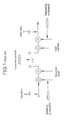
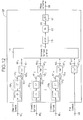
- Shown in Figure 1 is a simplified CDMA communication system that involves a single communication channel of a given bandwidth which is mixed by a spreading code which repeats a predetermined pattern generated by a pseudo-noise (pn) sequence generator.
- a data signal is modulated with the pn sequence producing a digital spread spectrum signal.
- a carrier signal is then modulated with the digital spread spectrum signal establishing a forward link, and transmitted.
- a receiver demodulates the transmission extracting the digital spread spectrum signal.
- the transmitted data is reproduced after correlation with the matching pn sequence. The same process is repeated to establish a reverse link.
- a transmitted signal is disturbed by reflection due to varying terrain and environmental conditions and man-made obstructions. This produces a plurality of received signals with differing time delays at the receiver. This effect is commonly known as multipath propagation. Moreover, each path arrives delayed at the receiver with a unique amplitude and carrier phase.
- the relative delays and amplitudes and phases must be determined. This determination can be performed with a modulated data signal, but typically, a more precise rendering is obtained when compared to an unmodulated signal. In most digital spread spectrum systems, it is more effective to use an unmodulated pilot signal discrete from the transmitted modulated data by assigning the pilot an individual pn sequence. A global-pilot signal is most valuable on systems where many signals are transmitted from a base station to multiple users.
- the global-pilot signal provides the same pilot sequence to the plurality of users serviced by that particular base station and is used for the initial acquisition of an individual user and for the user to obtain channel-estimates for coherent reception and for the combining of the multipath components.
- the global-pilot signal may use up to 10 percent of the forward direction air capacity.
- the present invention relates to a digital spread spectrum communication system that employs pilot-aided coherent multipath demodulation with a substantial reduction in global-pilot and assigned-pilot overheads.
- the system and method uses a QPSK- modulated data signal whereby the modulated data is removed and the recovered carrier is used for channel amplitude and phase estimation.
- the resulting signal has no data modulation and is used as a pseudo-pilot signal.
- a multiple-input phase-locked loop is employed further eliminating errors due to carrier-offset by using a plurality of pseudo-pilot signals.
- a pilot signal is still required to resolve absolute phase ambiguity, but at a greatly reduced magnitude.
- a B-CDMATM communication system 25 as shown in Figure 2 includes a transmitter 27 and a receiver 29 , which may reside in either a base station or a mobile user receiver.
- the transmitter 27 includes a signal processor 31 which encodes voice and nonvoice signals 33 into data at various rates, e.g. data rates of 8 kbps, 16 kbps, 32 kbps, or 64 kbps.
- the signal processor 31 selects a rate in dependence upon the type of signal, or in response to a set data rate.
- the input data 33 which can be considered a bi-phase modulated signal is encoded using forward error-correcting coding (FEC) 35 .
- FEC forward error-correcting coding
- the single bi-phase modulated data signal becomes bivariate or two bi-phase modulated signals.
- One signal is designated the in-phase channel I 41a.
- the other signal is designated the quadrature channel Q 41b.
- Bi-phase modulated I and Q signals are usually referred to as quadrature phase shift keying (QPSK).
- the two bi-phase modulated data or symbols 41a , 41b are spread with a complex pseudo-noise (pn) sequence.
- the resulting I 45a and Q 45b spread signals are combined 53 with other spread signals (channels) having different spreading codes, multiplied (mixed) with a carrier signal 51 , and transmitted 55 .
- the transmission 55 may contain a plurality of individual channels having different data rates.
- the receiver 29 includes a demodulator 57a , 57b which mixes down the transmitted broadband signal 55 into an intermediate carrier frequency 59a , 59b .
- a second down conversion reduces the signal to baseband.
- the QPSK signal is then filtered 61 and mixed 63a , 63b with the locally generated complex pn sequence 43a , 43b which matches the conjugate of the transmitted complex code. Only the original waveforms which were spread by the same code at the transmitter 27 will be effectively despread. Others will appear as noise to the receiver 29 .
- the data 65a , 65b is then passed onto a signal processor 59 where FEC decoding is performed on the convolutionally encoded data.
- a QPSK symbol consists of one bit each from both the in-phase (I) and quadrature (Q) signals.
- the bits may represent a quantized version of an analog sample or digital data. It can be seen that symbol duration t s is equal to bit duration.
- the transmitted symbols are spread by multiplying the QPSK symbol stream by a unique complex pn sequence.
- Both the I and Q pn sequences are comprised of a bit stream generated at a much higher rate, typically 100 to 200 times the symbol rate.
- One such pn sequence is shown in Figure 3C .
- the complex pn sequence is mixed with the complex-symbol bit stream producing the digital spread signal.
- the components of the spread signal are known as chips having a much smaller duration t c .
- the baseband signal When the signal is received and demodulated, the baseband signal is at the chip level. Both the I and Q components of the signal are despread using the conjugate of the pn sequence used during spreading, returning the signal to the symbol level.
- phase corruption experienced during transmission manifests itself by distorting the individual chip waveforms.
- Carrier-offset correction may also be performed at the symbol level, but with less overall accuracy. However, since the symbol rate is much less than the chip rate, less overall processing speed is required when the correction is done at the symbol level.
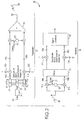
- a complex baseband digital spread spectrum signal 77 comprised of in-phase and quadrature phase components is input and filtered using an adaptive matched filter (AMF) 79 or other adaptive filtering means.
- the AMF 79 is a transversal filter (finite impulse response) which uses filter coefficients 81 to overlay delayed replicas of the received signal 77 onto each other to provide a filtered signal 83 having an increased signal-to-noise ratio (SNR).
- SNR signal-to-noise ratio
- the pilot signal 89 is despread with a separate despreader 87 and pn sequence 91 contemporaneous with the transmitted data 77 assigned to channels which are despread 85 1 , 85 2 , 85 n with pn sequences 93 1 , 93 2 , 93 n of their own.
- the data bit streams 95 1 , 95 2 , 95 n are coupled to Viterbi decoders 97 1 , 97 2 , 97 n and output 99 1 , 99 2 , 99 n .
- the filter coefficients 81, or weights, used in adjusting the AMF 79 are obtained by the demodulation of the individual multipath propagation paths. This operation is performed by a rake receiver 101.
- the use of a rake receiver 101 to compensate for multipath distortion is well known to those skilled in the communication arts.
- the rake receiver 101 consists of a parallel combination of path demodulators ("fingers") 103 0 , 103 1 , 103 2 , 103 n which demodulate a particular multipath component.
- the pilot sequence tracking loop of a particular demodulator is initiated by the timing estimation of a given path as determined by a pn sequence 105 .
- a pilot signal is used for despreading the individual signals of the rake.
- the pn sequence 105 may belong to any channel 93 1 of the communication system. The channel with the largest received signal is typically used.
- Each path demodulator includes a complex mixer 107 0 , 107 1 , 107 2 , 107 n , and summer and latch 109 0 , 109 1 , 109 2 , 109 n .
- the pn sequence 105 is delayed ⁇ 111 1 , 111 2 , 111 n by one chip and mixed 107 1 , 107 2 , 107 n with the baseband spread spectrum signal 113 thereby despreading each signal.
- Each multiplication product is input into an accumulator 109 0 , 109 1 , 109 2 , 109 n where it is added to the previous product and latched out after the next symbol-clock cycle.
- the rake receiver 101 provides relative path values for each multipath component.
- the plurality of n-dimension outputs 115 0 , 115 1 , 115 2 , 115 n provide estimates of the sampled channel impulse response that contain a relative phase error of either 0°, 90°, 180°, or 270°.
- the plurality of outputs from the rake receiver are coupled to an n-dimensional complex mixer 117 .
- Mixed with each rake receiver 101 output 115 is a correction to remove the relative phase error contained in the rake output.
- a pilot signal is also a complex QPSK signal, but with the quadrature component set at zero.
- the error correction 119 signal of the present invention is derived from the despread channel 95 1 by first performing a hard decision 121 on each of the symbols of the despread signal 95 1 .
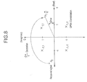
- a hard decision processor 121 determines the QPSK constellation position that is closest to the despread symbol value.
- the Euclidean distance processor compares a received symbol p o of channel 1 to the four QPSK constellation points x 1,1 , x -1,1 , x -1,-1 , x 1,-1 . It is necessary to examine each received symbol p o due to corruption during transmission 55 by noise and distortion, whether multipath or radio frequency.
- the hard decision processor 121 computes the four distances d 1 , d 2 , d 3 , d 4 to each quadrant from the received symbol p o and chooses the shortest distance d 2 and assigns that symbol location x -1,1 .
- the original symbol coordinates p o are discarded.
- a complex conjugate is one of a pair of complex numbers with identical real parts and with imaginary parts differing only in sign.
- a symbol is demodulated or derotated by first determining the complex conjugate of the assigned symbol coordinates x -1, -1 , forming the correction signal 119 which is used to remove the relative phase error contained in the rake output.
- the rake output is effectively derotated by the angle associated with the hard decision, removing the relative phase error. This operation effectively provides a rake that is driven by a pilot signal, but without an absolute phase reference.
- the output 119 from the complex conjugate 123 is coupled to a complex n-dimensional mixer 117 where each output of the rake receiver 101 is mixed with the correction signal 119.
- the resulting products 127 are noisy estimates of the channel impulse response p 1 as shown in Figure 8.
- the error shown in Figure 8 is indicated by a radian distance of ⁇ /6 from the in-phase axis.
- the outputs 129 of the complex n-dimensional mixer 117 are coupled to an n-dimensional channel estimator 131.
- the channel estimator 131 is a plurality of low-pass filters filtering each multipath component.
- the outputs of the n-dimensional mixer 117 are coupled to the AMF 79 . These signals act as the AMF 79 filter weights.
- the AMF 79 filters the baseband signal to compensate for channel distortion due to multipath without requiring a large magnitude pilot signal.
- Rake receivers 101 are used in conjunction with phase-locked loop (PLL) 133 circuits to remove carrier-offset.
- Carrier-offset occurs as a result of transmitter/receiver component mismatches and other RF distortion.
- the present invention 75 requires that a low level pilot signal 135 be produced by despreading 87 the pilot from the baseband signal 77 with a pilot pn sequence 91 .
- the pilot signal is coupled to a single input PLL 133 .
- the PLL 133 measures the phase difference between the pilot signal 135 and a reference phase of 0.
- the despread pilot signal 135 is the actual error signal coupled to the PLL 133.
- a conventional PLL 133 is shown in Figure 9.
- the PLL 133 includes an arctangent analyzer 136, complex filter 137, an integrator 139 and a phase-to-complex-number converter 141 .
- the pilot signal 135 is the error signal input to the PLL 133 and is coupled to the complex filter 137 .
- the complex filter 137 includes two gain stages, an integrator 145 and a summer 147 .
- the output from the complex filter is coupled to the integrator 139 .
- the integral of frequency is phase, which is output 140 to the converter 141 .
- the phase output 140 is coupled to a converter 141 which converts the phase signal into a complex signal for mixing 151 with the baseband signal 77 . Since the upstream operations are commutative, the output 149 of the PLL 133 is also the feedback loop into the system 75 .
- the process By implementing the hard decision 121 and derotation 123 of the data modulation, the process provides channel estimation without the use of a large pilot signal. If an error occurs during the hard decision process and the quadrant of the received data symbol is not assigned correctly, the process suffers a phase error. The probability of phase error is reduced, however, due to the increased signal-to-noise ratio of the traffic channel. The errors that occur are filtered out during the channel-estimation and carrier-recovery processes.
- the traffic channel is approximately 6 dB stronger (2x) than the level of the despread pilot.
- the present invention can also be performed with carrier-offset correction at the symbol level.
- An alternative embodiment 150 implemented at the symbol level is shown in Figure 10 .
- the difference between the chip and symbol level processes occur where the output of the conventional PLL 133 is combined.
- the PLL output 140 does not undergo chip conversion 141 and is introduced into the AMF 79 weights after the rake receiver 101 by another n-dimensional mixer 153 .
- the phase correction 140 feedback must also be mixed 154 1 , 154 2 , 154 n with the outputs 95 1 , 95 2 , 95 n of each of the plurality of channel despreaders 85 1 , 85 2 , 85 n and mixed 156 with the output 135 of the pilot despreader 87 .
- another alternative embodiment 193 uses a variation of the earlier embodiments whereby a hard decision is rendered on each received symbol after despreading and derotated by a radian amount equal to the complex conjugate.
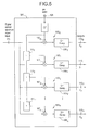
- the alternate approach 193 uses a plurality of channel despreaders 85 1 , 85 2 , 85 n and the pilot despreader 87 as inputs to a multiple input phase-locked loop (MIPLL) 157 shown in Figure 12. Since each of the despread channels 95 1 , 95 2 , 95 n contains an ambiguous representation of the pilot signal, a small signal pilot 135 is required to serve as an absolute reference. The despread symbols from all channels in conjunction with the despread small signal pilot signal are input to the MIPLL 157.
- MIPLL phase-locked loop
- each channel 95 1 , 95 2 , 95 n is coupled to a hard decision/complex conjugate operation 159 1 , 159 2 , 159 n .
- the derotated pseudo-pilots 161 1 , 161 2 , 161 n are then mixed with the delayed symbols producing a complex voltage error 163 1 , 163 2 , 163 n .
- the error 165 1 , 165 2 , 165 n is input into a converter 167 1 , 167 2 , 167 n , 167 n+1 which takes an inverse tangent converting the complex number into a phase error 169 1 , 169 2 , 169 n , 169 n+1 .
- Each phase error 169 1 , 169 2 , 169 n , 169 n+1 is input into a maximum likelihood combiner 171 which assigns various weights to the plurality of inputs and produces a sum output. Also included in the sum is the small signal pilot 135 phase 169 n+1 which is despread 135 and converted 167 n+1 . The weighting of the small pilot signal may be emphasized since its phase is unambiguous.
- the output of the combiner 173 is the estimate of the carrier-offset and is coupled to a complex filter 175 and coupled to an integrator 177 . All channels contribute to the estimate of the carrier-offset frequency with the absolute phase error removed by the unambiguous pilot signal.
- the integrator accumulates the history of the summed signal over many samples. After integration, the estimate of the phase error is output 179 converted to a complex voltage and output 183 .
- the output 183 of the MIPLL 157 is coupled to a complex mixer 185 upstream of the rake receiver. This completes the error feedback for the MIPLL 157. Even though this embodiment requires additional resources and complexity, the MIPLL 157 architecture can be efficiently implemented and executed in a digital signal processor (DSP).
- DSP digital signal processor
- this embodiment 195 mixes the output of the MIPLL 157 at the symbol level.
- the MIPLL 157 is mixed 197 with the output of the rake receiver 101 .
- the output of the rake receiver 101 is at the symbol level.
- the symbol-to-chip conversion 181 in the MIPLL 157 architecture is disabled. Since the output 183 of the MIPLL 157 is mixed with the outputs of the rake 101 which are used only for the AMF 79 weights, the phase correction for carrier-offset must be added to the portion of the receiver that processes traffic data.
- a plurality of mixers 199 1 , 199 2 , 199 n downstream of each channel despreader 85 1 , 85 2 , 85 n and a mixer 193 downstream of the pilot despreader 87 are therefore required to mix the phase-corrected output 183 (at the symbol level) as feedback into the system.
- the present invention maintains the transmitted pilot signal at a low level to provide an absolute phase reference while reducing pilot interference and increasing air capacity.
- the net effect is the virtual elimination of the pilot overhead.
Landscapes
- Engineering & Computer Science (AREA)
- Computer Networks & Wireless Communication (AREA)
- Signal Processing (AREA)
- Noise Elimination (AREA)
- Mobile Radio Communication Systems (AREA)
- Digital Transmission Methods That Use Modulated Carrier Waves (AREA)
- Circuits Of Receivers In General (AREA)
- Stereo-Broadcasting Methods (AREA)
- Input Circuits Of Receivers And Coupling Of Receivers And Audio Equipment (AREA)
- Radio Relay Systems (AREA)
Applications Claiming Priority (4)
| Application Number | Priority Date | Filing Date | Title |
|---|---|---|---|
| US09/078,417 US6366607B1 (en) | 1998-05-14 | 1998-05-14 | Processing for improved performance and reduced pilot |
| US78417 | 1998-05-14 | ||
| EP99904364A EP1076938B1 (de) | 1998-05-14 | 1999-01-27 | Cdma-empfänger für mehrwegausbreitung und reduziertes pilotsignal |
| EP02025627A EP1283602B1 (de) | 1998-05-14 | 1999-01-27 | CDMA-Empfänger für Mehrwegausbreitung und reduziertes Pilotsignal |
Related Parent Applications (1)
| Application Number | Title | Priority Date | Filing Date |
|---|---|---|---|
| EP02025627A Division EP1283602B1 (de) | 1998-05-14 | 1999-01-27 | CDMA-Empfänger für Mehrwegausbreitung und reduziertes Pilotsignal |
Publications (2)
| Publication Number | Publication Date |
|---|---|
| EP1429469A2 true EP1429469A2 (de) | 2004-06-16 |
| EP1429469A3 EP1429469A3 (de) | 2004-06-30 |
Family
ID=22143895
Family Applications (3)
| Application Number | Title | Priority Date | Filing Date |
|---|---|---|---|
| EP99904364A Expired - Lifetime EP1076938B1 (de) | 1998-05-14 | 1999-01-27 | Cdma-empfänger für mehrwegausbreitung und reduziertes pilotsignal |
| EP02025627A Expired - Lifetime EP1283602B1 (de) | 1998-05-14 | 1999-01-27 | CDMA-Empfänger für Mehrwegausbreitung und reduziertes Pilotsignal |
| EP04006118A Withdrawn EP1429469A3 (de) | 1998-05-14 | 1999-01-27 | CDMA-Empfänger für Mehrwegausbreitung und reduziertes Pilotsignal |
Family Applications Before (2)
| Application Number | Title | Priority Date | Filing Date |
|---|---|---|---|
| EP99904364A Expired - Lifetime EP1076938B1 (de) | 1998-05-14 | 1999-01-27 | Cdma-empfänger für mehrwegausbreitung und reduziertes pilotsignal |
| EP02025627A Expired - Lifetime EP1283602B1 (de) | 1998-05-14 | 1999-01-27 | CDMA-Empfänger für Mehrwegausbreitung und reduziertes Pilotsignal |
Country Status (15)
| Country | Link |
|---|---|
| US (10) | US6366607B1 (de) |
| EP (3) | EP1076938B1 (de) |
| JP (2) | JP4004229B2 (de) |
| KR (1) | KR100629701B1 (de) |
| CN (3) | CN100530995C (de) |
| AT (2) | ATE262240T1 (de) |
| AU (1) | AU2477699A (de) |
| BR (1) | BR9910412A (de) |
| CA (1) | CA2330703A1 (de) |
| DE (2) | DE69915714T2 (de) |
| ES (2) | ES2189387T3 (de) |
| IL (1) | IL139057A (de) |
| SG (1) | SG111970A1 (de) |
| TR (1) | TR200003340T2 (de) |
| WO (1) | WO1999059259A1 (de) |
Cited By (1)
| Publication number | Priority date | Publication date | Assignee | Title |
|---|---|---|---|---|
| WO2006027603A1 (en) | 2004-09-10 | 2006-03-16 | Ttpcom Limited | Method and apparatus for selecting a channel filter for a communication system |
Families Citing this family (44)
| Publication number | Priority date | Publication date | Assignee | Title |
|---|---|---|---|---|
| US6259687B1 (en) * | 1997-10-31 | 2001-07-10 | Interdigital Technology Corporation | Communication station with multiple antennas |
| US6366607B1 (en) * | 1998-05-14 | 2002-04-02 | Interdigital Technology Corporation | Processing for improved performance and reduced pilot |
| US6498784B1 (en) | 1998-10-20 | 2002-12-24 | Interdigital Technology Corporation | Cancellation of pilot and traffic signals |
| US8180675B2 (en) * | 2000-08-31 | 2012-05-15 | Prime Research Alliance E., Inc. | System and method for automatically managing avail inventory data and avail pricing |
| KR100318950B1 (ko) * | 1998-12-26 | 2001-12-29 | 윤종용 | 멀티코드 이동통신시스템에서 왜곡 보상장치 및 방법 |
| JP2001016135A (ja) | 1999-06-29 | 2001-01-19 | Nec Corp | 自動周波数制御方法と自動周波数制御方式とcdma受信機 |
| JP3715141B2 (ja) * | 1999-07-13 | 2005-11-09 | 松下電器産業株式会社 | 通信端末装置 |
| US6560299B1 (en) * | 1999-07-30 | 2003-05-06 | Christopher H Strolle | Diversity receiver with joint signal processing |
| KR20010035967A (ko) * | 1999-10-05 | 2001-05-07 | 서평원 | 코드분할다중접속 시스템의 다중 사용자 신호 동기 획득 장치 및 그 방법 |
| US6621857B1 (en) | 1999-12-31 | 2003-09-16 | Thomson Licensing S.A. | Carrier tracking loop for direct sequence spread spectrum systems |
| BR0109904A (pt) * | 2000-03-28 | 2004-03-30 | Interdigital Tech Corp | Sistema de cdma que utiliza rotação prévia antes da transmissão |
| DE10052392A1 (de) * | 2000-10-20 | 2002-05-02 | Alcatel Sa | Basisstation eines funkbetriebenen Kommunikationssystems |
| FR2816776B1 (fr) * | 2000-11-10 | 2003-02-07 | Cit Alcatel | Procede de correction de l'erreur de frequence |
| US6754253B2 (en) * | 2000-11-29 | 2004-06-22 | Ericsson Inc. | Receiver architecture for transmit diversity in CDMA system |
| US7069545B2 (en) * | 2000-12-29 | 2006-06-27 | Intel Corporation | Quantization and compression for computation reuse |
| US6990137B2 (en) * | 2001-05-17 | 2006-01-24 | Qualcomm, Incorporated | System and method for received signal prediction in wireless communications systems |
| US7170924B2 (en) * | 2001-05-17 | 2007-01-30 | Qualcomm, Inc. | System and method for adjusting combiner weights using an adaptive algorithm in wireless communications system |
| US7333530B1 (en) * | 2001-08-06 | 2008-02-19 | Analog Devices, Inc. | Despread signal recovery in digital signal processors |
| US7230975B2 (en) * | 2001-08-07 | 2007-06-12 | Qualcomm Incorporated | Adaptive pilot filter for a wireless communication system |
| WO2003032546A1 (en) * | 2001-09-28 | 2003-04-17 | Fujitsu Limited | Channel inferring device and method |
| US7023902B2 (en) * | 2001-11-06 | 2006-04-04 | Qualcomm Inc. | Apparatus and method for scalable offline CDMA demodulation |
| US7801085B1 (en) * | 2002-06-03 | 2010-09-21 | Ericsson Ab | System and method of processing CDMA signals |
| US7130329B2 (en) * | 2002-07-08 | 2006-10-31 | Qualcomm Incorporated | Apparatus and method for radio frequency tracking and acquisition |
| AU2002354332A1 (en) * | 2002-11-08 | 2004-06-07 | Pirelli And C.S.P.A. | Optical communication line and system with reduced polarization mode dispersion |
| US7180963B2 (en) * | 2002-11-25 | 2007-02-20 | Ali Corporation | Digital receiver capable of processing modulated signals at various data rates |
| US7302233B2 (en) * | 2003-06-23 | 2007-11-27 | Texas Instruments Incorporated | Multiuser detection for wireless communications systems in the presence of interference |
| JP4183613B2 (ja) * | 2003-12-26 | 2008-11-19 | 三洋電機株式会社 | 受信方法および装置 |
| CN1300949C (zh) * | 2004-06-07 | 2007-02-14 | 东南大学 | 一种切普均衡器与瑞克接收机并行接收的方法 |
| JP4886276B2 (ja) * | 2005-11-17 | 2012-02-29 | ザインエレクトロニクス株式会社 | クロックデータ復元装置 |
| US7764728B2 (en) * | 2006-10-18 | 2010-07-27 | Via Technologies, Inc. | Apparatus and method for reducing complexity of matched filter |
| US7868819B2 (en) * | 2007-09-07 | 2011-01-11 | The Board Of Trustees Of The Leland Stanford Junior University | Arrangements for satellite-based navigation and methods therefor |
| US7990929B2 (en) * | 2007-11-27 | 2011-08-02 | Harris Corporation | Wireless communications device including rake finger stage providing frequency correction and related methods |
| US8520721B2 (en) | 2008-03-18 | 2013-08-27 | On-Ramp Wireless, Inc. | RSSI measurement mechanism in the presence of pulsed jammers |
| US20090239550A1 (en) * | 2008-03-18 | 2009-09-24 | Myers Theodore J | Random phase multiple access system with location tracking |
| US8477830B2 (en) | 2008-03-18 | 2013-07-02 | On-Ramp Wireless, Inc. | Light monitoring system using a random phase multiple access system |
| US7733945B2 (en) | 2008-03-18 | 2010-06-08 | On-Ramp Wireless, Inc. | Spread spectrum with doppler optimization |
| US7593452B1 (en) | 2008-03-18 | 2009-09-22 | On-Ramp Wireless, Inc. | Despreading spread spectrum data |
| US8958460B2 (en) | 2008-03-18 | 2015-02-17 | On-Ramp Wireless, Inc. | Forward error correction media access control system |
| US7773664B2 (en) | 2008-03-18 | 2010-08-10 | On-Ramp Wireless, Inc. | Random phase multiple access system with meshing |
| US8363699B2 (en) | 2009-03-20 | 2013-01-29 | On-Ramp Wireless, Inc. | Random timing offset determination |
| US7639726B1 (en) | 2009-03-20 | 2009-12-29 | On-Ramp Wireless, Inc. | Downlink communication |
| US7702290B1 (en) | 2009-04-08 | 2010-04-20 | On-Ramp Wirless, Inc. | Dynamic energy control |
| US9044525B2 (en) | 2011-06-29 | 2015-06-02 | Nippon Shokubai Co., Ltd. | Polyacrylic acid (salt)-based water absorbent resin powder and method for producing the same |
| CN108897014A (zh) * | 2018-07-25 | 2018-11-27 | 航天恒星科技有限公司 | 一种无模糊度接收boc导航信号的抗多径方法 |
Family Cites Families (23)
| Publication number | Priority date | Publication date | Assignee | Title |
|---|---|---|---|---|
| US5579338A (en) | 1992-06-29 | 1996-11-26 | Mitsubishi Denki Kabushiki Kaisha | Spread spectrum receiver using partial correlations |
| CN1068477C (zh) | 1993-08-06 | 2001-07-11 | Ntt移运通信网株式会社 | 扩频通信的接收机和中继器 |
| CN1035586C (zh) | 1993-10-13 | 1997-08-06 | Ntt移动通信网株式会社 | 扩频通信接收机 |
| KR950035142A (ko) | 1994-03-10 | 1995-12-30 | 가나미야지 준 | 수신장치, 기지국 수신 시스템 및 이동국 수신시스템 |
| EP0716520B1 (de) | 1994-06-23 | 2004-05-12 | NTT DoCoMo, Inc. | Cdma demodulationsschaltung und -verfahren |
| US5920555A (en) | 1994-07-28 | 1999-07-06 | Roke Manor Research Limited | Pilot assisted direct sequence spread spectrum synchronization apparatus |
| GB2292053B (en) * | 1994-07-28 | 1998-08-26 | Roke Manor Research | Synchronisation apparatus |
| US5619524A (en) * | 1994-10-04 | 1997-04-08 | Motorola, Inc. | Method and apparatus for coherent communication reception in a spread-spectrum communication system |
| US5724378A (en) | 1994-12-13 | 1998-03-03 | Nit Mobile Communications Network, Inc. | CDMA multiuser receiver and method |
| JPH08172464A (ja) * | 1994-12-20 | 1996-07-02 | Fujitsu Ltd | キャリア位相制御回路 |
| US5692006A (en) | 1995-07-31 | 1997-11-25 | Qualcomm Incorporated | Adaptive despreader |
| US6356555B1 (en) * | 1995-08-25 | 2002-03-12 | Terayon Communications Systems, Inc. | Apparatus and method for digital data transmission using orthogonal codes |
| US5745837A (en) | 1995-08-25 | 1998-04-28 | Terayon Corporation | Apparatus and method for digital data transmission over a CATV system using an ATM transport protocol and SCDMA |
| US5930288A (en) * | 1996-05-06 | 1999-07-27 | Motorola, Inc. | Time-shared lock indicator circuit and method for power control and traffic channel decoding in a radio receiver |
| US5768307A (en) | 1996-09-13 | 1998-06-16 | Telefonaktiebolaget Lm Ericsson | Coherent demodulation with decision-directed channel estimation for digital communication |
| CA2214163C (en) * | 1996-09-27 | 2001-07-31 | Nec Corporation | Method and apparatus for preamble-less demodulation |
| US6192068B1 (en) * | 1996-10-03 | 2001-02-20 | Wi-Lan Inc. | Multicode spread spectrum communications system |
| JP3006679B2 (ja) * | 1997-01-16 | 2000-02-07 | 日本電気株式会社 | セルラー移動電話システム |
| US5943331A (en) * | 1997-02-28 | 1999-08-24 | Interdigital Technology Corporation | Orthogonal code synchronization system and method for spread spectrum CDMA communications |
| US6055231A (en) * | 1997-03-12 | 2000-04-25 | Interdigital Technology Corporation | Continuously adjusted-bandwidth discrete-time phase-locked loop |
| US6366607B1 (en) * | 1998-05-14 | 2002-04-02 | Interdigital Technology Corporation | Processing for improved performance and reduced pilot |
| BR0109904A (pt) * | 2000-03-28 | 2004-03-30 | Interdigital Tech Corp | Sistema de cdma que utiliza rotação prévia antes da transmissão |
| US7075973B2 (en) * | 2003-03-03 | 2006-07-11 | Interdigital Technology Corporation | Multiuser detection of differing data rate signals |
-
1998
- 1998-05-14 US US09/078,417 patent/US6366607B1/en not_active Expired - Lifetime
-
1999
- 1999-01-27 CN CNB2006100958923A patent/CN100530995C/zh not_active Expired - Fee Related
- 1999-01-27 IL IL13905799A patent/IL139057A/en not_active IP Right Cessation
- 1999-01-27 CN CNA200310104541A patent/CN1501614A/zh active Pending
- 1999-01-27 CA CA002330703A patent/CA2330703A1/en not_active Abandoned
- 1999-01-27 DE DE69915714T patent/DE69915714T2/de not_active Expired - Lifetime
- 1999-01-27 DE DE69904039T patent/DE69904039T2/de not_active Expired - Lifetime
- 1999-01-27 CN CNB998060925A patent/CN1213547C/zh not_active Expired - Fee Related
- 1999-01-27 EP EP99904364A patent/EP1076938B1/de not_active Expired - Lifetime
- 1999-01-27 EP EP02025627A patent/EP1283602B1/de not_active Expired - Lifetime
- 1999-01-27 WO PCT/US1999/001794 patent/WO1999059259A1/en not_active Ceased
- 1999-01-27 SG SG200206308A patent/SG111970A1/en unknown
- 1999-01-27 AT AT02025627T patent/ATE262240T1/de not_active IP Right Cessation
- 1999-01-27 ES ES99904364T patent/ES2189387T3/es not_active Expired - Lifetime
- 1999-01-27 KR KR1020007012655A patent/KR100629701B1/ko not_active Expired - Fee Related
- 1999-01-27 BR BR9910412-1A patent/BR9910412A/pt not_active IP Right Cessation
- 1999-01-27 AU AU24776/99A patent/AU2477699A/en not_active Abandoned
- 1999-01-27 ES ES02025627T patent/ES2218498T3/es not_active Expired - Lifetime
- 1999-01-27 JP JP2000548967A patent/JP4004229B2/ja not_active Expired - Fee Related
- 1999-01-27 TR TR2000/03340T patent/TR200003340T2/xx unknown
- 1999-01-27 EP EP04006118A patent/EP1429469A3/de not_active Withdrawn
- 1999-01-27 AT AT99904364T patent/ATE228278T1/de not_active IP Right Cessation
-
2001
- 2001-11-13 US US10/008,411 patent/US6483868B2/en not_active Expired - Lifetime
-
2002
- 2002-01-11 US US10/043,850 patent/US6516022B2/en not_active Expired - Lifetime
- 2002-04-01 US US10/113,186 patent/US6480530B2/en not_active Expired - Lifetime
-
2003
- 2003-02-03 US US10/357,869 patent/US6707845B2/en not_active Expired - Lifetime
-
2004
- 2004-01-26 US US10/764,763 patent/US6944209B2/en not_active Expired - Fee Related
-
2005
- 2005-07-26 US US11/189,370 patent/US7110443B2/en not_active Expired - Fee Related
-
2006
- 2006-09-18 US US11/532,589 patent/US7949037B2/en not_active Expired - Fee Related
-
2007
- 2007-07-20 JP JP2007190139A patent/JP4566222B2/ja not_active Expired - Fee Related
-
2011
- 2011-04-13 US US13/086,091 patent/US8254431B2/en not_active Expired - Fee Related
-
2012
- 2012-08-24 US US13/594,447 patent/US8582625B2/en not_active Expired - Fee Related
Cited By (3)
| Publication number | Priority date | Publication date | Assignee | Title |
|---|---|---|---|---|
| WO2006027603A1 (en) | 2004-09-10 | 2006-03-16 | Ttpcom Limited | Method and apparatus for selecting a channel filter for a communication system |
| CN101015127B (zh) * | 2004-09-10 | 2010-09-29 | 开曼晨星半导体公司 | 供通信系统选择信道滤波器的方法及装置 |
| US8743910B2 (en) | 2004-09-10 | 2014-06-03 | Mstar Semiconductor, Inc. | Method and apparatus for selecting a channel filter for a communication system |
Also Published As
Similar Documents
| Publication | Publication Date | Title |
|---|---|---|
| EP1283602B1 (de) | CDMA-Empfänger für Mehrwegausbreitung und reduziertes Pilotsignal | |
| US6606345B2 (en) | Base station which uses pre-rotation before transmission | |
| HK1035814B (en) | Multipath cdma receiver for reduced pilot | |
| HK1100107A (en) | Multipath cdma receiver for reduced pilot | |
| HK1063895A (en) | Multipath cdma receiver for reduced pilot | |
| MXPA00010222A (en) | Multipath cdma receiver for reduced pilot |
Legal Events
| Date | Code | Title | Description |
|---|---|---|---|
| PUAI | Public reference made under article 153(3) epc to a published international application that has entered the european phase |
Free format text: ORIGINAL CODE: 0009012 |
|
| PUAL | Search report despatched |
Free format text: ORIGINAL CODE: 0009013 |
|
| 17P | Request for examination filed |
Effective date: 20040315 |
|
| AC | Divisional application: reference to earlier application |
Ref document number: 1076938 Country of ref document: EP Kind code of ref document: P Ref document number: 1283602 Country of ref document: EP Kind code of ref document: P |
|
| AK | Designated contracting states |
Kind code of ref document: A2 Designated state(s): AT BE CH CY DE DK ES FI FR GB GR IE IT LI LU MC NL PT SE |
|
| AK | Designated contracting states |
Kind code of ref document: A3 Designated state(s): AT BE CH CY DE DK ES FI FR GB GR IE IT LI LU MC NL PT SE |
|
| RIN1 | Information on inventor provided before grant (corrected) |
Inventor name: OZLUTURK, FATIH M. Inventor name: JACQUES, ALEXANDER M. Inventor name: MESECHER, DAVID K. |
|
| AKX | Designation fees paid |
Designated state(s): AT BE CH CY DE DK ES FI FR GB GR IE IT LI LU MC NL PT SE |
|
| RAP1 | Party data changed (applicant data changed or rights of an application transferred) |
Owner name: INTERDIGITAL TECHNOLOGY CORPORATION |
|
| 17Q | First examination report despatched |
Effective date: 20070302 |
|
| STAA | Information on the status of an ep patent application or granted ep patent |
Free format text: STATUS: THE APPLICATION IS DEEMED TO BE WITHDRAWN |
|
| 18D | Application deemed to be withdrawn |
Effective date: 20101028 |