EP1429439A1 - Reverse battery protection circuit - Google Patents
Reverse battery protection circuit Download PDFInfo
- Publication number
- EP1429439A1 EP1429439A1 EP03028010A EP03028010A EP1429439A1 EP 1429439 A1 EP1429439 A1 EP 1429439A1 EP 03028010 A EP03028010 A EP 03028010A EP 03028010 A EP03028010 A EP 03028010A EP 1429439 A1 EP1429439 A1 EP 1429439A1
- Authority
- EP
- European Patent Office
- Prior art keywords
- circuit
- semiconductor switch
- load
- controlled semiconductor
- reverse battery
- Prior art date
- Legal status (The legal status is an assumption and is not a legal conclusion. Google has not performed a legal analysis and makes no representation as to the accuracy of the status listed.)
- Withdrawn
Links
Images

Classifications
-
- H—ELECTRICITY
- H02—GENERATION; CONVERSION OR DISTRIBUTION OF ELECTRIC POWER
- H02H—EMERGENCY PROTECTIVE CIRCUIT ARRANGEMENTS
- H02H11/00—Emergency protective circuit arrangements for preventing the switching-on in case an undesired electric working condition might result
- H02H11/002—Emergency protective circuit arrangements for preventing the switching-on in case an undesired electric working condition might result in case of inverted polarity or connection; with switching for obtaining correct connection
- H02H11/003—Emergency protective circuit arrangements for preventing the switching-on in case an undesired electric working condition might result in case of inverted polarity or connection; with switching for obtaining correct connection using a field effect transistor as protecting element in one of the supply lines
-
- H—ELECTRICITY
- H02—GENERATION; CONVERSION OR DISTRIBUTION OF ELECTRIC POWER
- H02J—ELECTRIC POWER NETWORKS; CIRCUIT ARRANGEMENTS OR SYSTEMS FOR SUPPLYING OR DISTRIBUTING ELECTRIC POWER; SYSTEMS FOR STORING ELECTRIC ENERGY
- H02J7/00—Circuit arrangements for charging or discharging batteries or for supplying loads from batteries
- H02J7/60—Circuit arrangements for charging or discharging batteries or for supplying loads from batteries including safety or protection arrangements
- H02J7/68—Circuit arrangements for charging or discharging batteries or for supplying loads from batteries including safety or protection arrangements using circuits for correcting or protecting against reverse-polarity
Definitions
- Fig. 1 shows a typical configuration where such a such a scheme is used where the FET is in the -ve DC path which reduces the complexity of the drive circuit for the reverse battery FET.
- the duration of the current flow through the freewheeling diode is of a low duty cycle (such as simple low frequency PWM fan controls, solid state relays (SSRs), engine start systems and load disconnect devices).
- a low duty cycle such as simple low frequency PWM fan controls, solid state relays (SSRs), engine start systems and load disconnect devices.
- the invention provides an alternative solution to the reverse battery protection problem that is simple and low cost.
- a reverse battery protection circuit comprising a first controlled semiconductor switch for providing current to a load and coupled in series with load terminals across which load terminals the load is adapted to be connected, and a second controlled semiconductor switch disposed in a series circuit with a free wheeling diode, the series circuit being coupled across the load terminals.
- the alternate approach places the reverse battery FET in the 'freewheeling diode' path and polarized such that the intrinsic diode of the FET will oppose any applied reverse voltage.
- the reverse battery FET protects the module itself from short circuiting the applied -ve voltage but does not protect the load from the negative voltage. This may be permissible in many application such as motors where the motor will simply rotate in the reverse direction for the time the reverse battery connection is made.
- the method of operation of the circuit is that whenever the main FET turns on, it causes the Vgs of the reverse battery FET to go to a low value that turns it off.
- the main FET turns off, the voltage from its drain to source goes high and thus this voltage is applied to the Vgs of the reverse battery FET which turns on and allows the current to freewheel.
- a zener diode may be necessary for protecting the gate from voltages over its rating.
- the average current that needs to be carried by the reverse battery FET is low and hence a smaller FET as well as a smaller heatsink can be used.
- Utilizing the Vds voltage of the main FET to turn on the reverse battery FET allows the user to avoid the requirement of using a special driver for this second FET and helps reduce costs even more.
- the reverse battery FET When the circuit of Fig. 2 has the battery connections reversed, the reverse battery FET is turned off, thereby preventing short circuiting of the Ve bus if the main FET is on.
- the intrinsic diode of the reverse battery FET is reversed biased during reverse battery connection. As described above, during reverse battery connection, the load is not protected from the negative voltage, but this is acceptable in many applications, such as motors, where the motor will simply rotate in reverse during reverse battery connection.
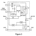
- Fig. 3 shows an alternative embodiment.
- Q1 is the main FET and Q2 is the reverse battery FET connected in series with the free wheeling diode D1.
- the driver IC drives Q1 and receives battery power on VBAT via diode D2 and ground.
- the driver IC is controlled from input PWM Command and provides a status output on line Status.
- Transistor Q2 is turned on via resistor R2 when proper battery connections are made, allowing diode D1 to free wheel. When the battery connections are reversed, Q2 is turned off and its intrinsic diode (not shown) is back biased.
Landscapes
- Engineering & Computer Science (AREA)
- Power Engineering (AREA)
- Charge And Discharge Circuits For Batteries Or The Like (AREA)
- Control Of Direct Current Motors (AREA)
Abstract
Description
- Most battery powered applications require reverse battery protection which protects equipment from damage due to a misconnected battery and the consequent polarity inversion. In many cases a simple diode in the +ve or -ve bus can offer adequate protection. In cases of large current systems, a FET may be used to reduce the voltage drop and thus reduce the power losses and consequently reduce the size of the heatsink.
- Fig. 1 shows a typical configuration where such a such a scheme is used where the FET is in the -ve DC path which reduces the complexity of the drive circuit for the reverse battery FET.
- Placing the reverse battery FET in the position of figure 1 (i.e. in the -ve rail) causes equal current in the reverse battery FET as in the main FET. This implies that a large amount of silicon needs to be used in conjunction with a larger heatsink.
- In many systems the duration of the current flow through the freewheeling diode is of a low duty cycle (such as simple low frequency PWM fan controls, solid state relays (SSRs), engine start systems and load disconnect devices). In these application it is advantageous to use an alternate scheme.
- The invention provides an alternative solution to the reverse battery protection problem that is simple and low cost.
- According to the invention, a reverse battery protection circuit is provided comprising a first controlled semiconductor switch for providing current to a load and coupled in series with load terminals across which load terminals the load is adapted to be connected, and a second controlled semiconductor switch disposed in a series circuit with a free wheeling diode, the series circuit being coupled across the load terminals.
- Other features and advantages of the present invention will become apparent from the following description of the invention which refers to the accompanying drawings.
-
- Fig. 1 shows a prior art reverse battery protection circuit;
- Fig. 2 shows the circuit according to the invention; and
- Fig. 3 shows an alternative embodiment of the invention.
-
- With reference now to Fig. 2, the alternate approach places the reverse battery FET in the 'freewheeling diode' path and polarized such that the intrinsic diode of the FET will oppose any applied reverse voltage. In this case it is important to note that the reverse battery FET protects the module itself from short circuiting the applied -ve voltage but does not protect the load from the negative voltage. This may be permissible in many application such as motors where the motor will simply rotate in the reverse direction for the time the reverse battery connection is made.
- The method of operation of the circuit is that whenever the main FET turns on, it causes the Vgs of the reverse battery FET to go to a low value that turns it off. When the main FET turns off, the voltage from its drain to source goes high and thus this voltage is applied to the Vgs of the reverse battery FET which turns on and allows the current to freewheel. A zener diode may be necessary for protecting the gate from voltages over its rating.
- As the application has the freewheeling current occurring for a short duration, the average current that needs to be carried by the reverse battery FET is low and hence a smaller FET as well as a smaller heatsink can be used.
- Utilizing the Vds voltage of the main FET to turn on the reverse battery FET allows the user to avoid the requirement of using a special driver for this second FET and helps reduce costs even more.
- When the circuit of Fig. 2 has the battery connections reversed, the reverse battery FET is turned off, thereby preventing short circuiting of the Ve bus if the main FET is on. The intrinsic diode of the reverse battery FET is reversed biased during reverse battery connection. As described above, during reverse battery connection, the load is not protected from the negative voltage, but this is acceptable in many applications, such as motors, where the motor will simply rotate in reverse during reverse battery connection.
- Fig. 3 shows an alternative embodiment. In Fig. 3, Q1 is the main FET and Q2 is the reverse battery FET connected in series with the free wheeling diode D1. The driver IC drives Q1 and receives battery power on VBAT via diode D2 and ground. The driver IC is controlled from input PWM Command and provides a status output on line Status. Transistor Q2 is turned on via resistor R2 when proper battery connections are made, allowing diode D1 to free wheel. When the battery connections are reversed, Q2 is turned off and its intrinsic diode (not shown) is back biased.
- Although the present invention has been described in relation to particular embodiments thereof, many other variations and modifications and other uses will become apparent to those skilled in the art. Therefore, the present invention should be limited not by the specific disclosure herein, but only by the appended claims.
Claims (6)
- A reverse battery protection circuit comprising:a first controlled semiconductor switch for providing current to a load and coupled in series with load terminals across which load terminals the load is adapted to be connected; anda second controlled semiconductor switch disposed in a series circuit with a free wheeling diode, the series circuit being coupled across the load terminals.
- The circuit of claim 1, wherein the second controlled semiconductor switch has a control electrode coupled to a main current carrying electrode of the main switch.
- The circuit of claim 1, wherein the semiconductor switches comprise FETs.
- The circuit of claim 3, wherein the control electrode of the second controlled semiconductor switch is coupled to the drain of the first controlled semiconductor switch.
- The circuit of claim 4, further comprising a zener diode coupled between gate and source of the second controlled semiconductor switch.
- The circuit of claim 1, further comprising a driver circuit for the first controlled semiconductor switch.
Applications Claiming Priority (4)
| Application Number | Priority Date | Filing Date | Title |
|---|---|---|---|
| US43115502P | 2002-12-05 | 2002-12-05 | |
| US431155P | 2002-12-05 | ||
| US726894 | 2003-12-02 | ||
| US10/726,894 US6969971B2 (en) | 2002-12-05 | 2003-12-02 | Reverse battery protection circuit |
Publications (1)
| Publication Number | Publication Date |
|---|---|
| EP1429439A1 true EP1429439A1 (en) | 2004-06-16 |
Family
ID=32329329
Family Applications (1)
| Application Number | Title | Priority Date | Filing Date |
|---|---|---|---|
| EP03028010A Withdrawn EP1429439A1 (en) | 2002-12-05 | 2003-12-05 | Reverse battery protection circuit |
Country Status (2)
| Country | Link |
|---|---|
| US (1) | US6969971B2 (en) |
| EP (1) | EP1429439A1 (en) |
Cited By (4)
| Publication number | Priority date | Publication date | Assignee | Title |
|---|---|---|---|---|
| DE102005007123A1 (en) * | 2005-02-17 | 2006-08-24 | Audi Ag | Motor vehicle`s electrical system, has voltage reversal protection device arranged between ground and connection point which is formed between switch and diode, and connected in series with diode which is arranged in converter |
| WO2008080793A1 (en) * | 2007-01-04 | 2008-07-10 | Continental Teves Ag & Co. Ohg | Motor vehicle controller with polarity-reversal protection |
| FR2977403A1 (en) * | 2011-07-01 | 2013-01-04 | Accumulateurs Fixes | Disconnection circuit for disconnecting rechargeable battery i.e. lithium-ion battery for e.g. car, has switch arranged in parallel to terminals of battery, and another switch arranged in series to one of terminals of battery |
| WO2020169209A1 (en) * | 2019-02-22 | 2020-08-27 | Incell International Ab | Reverse polarity protected battery module |
Families Citing this family (4)
| Publication number | Priority date | Publication date | Assignee | Title |
|---|---|---|---|---|
| DE102005011520A1 (en) * | 2005-03-10 | 2006-10-05 | Danfoss Compressors Gmbh | Apparatus and method for providing a DC voltage |
| KR101816357B1 (en) * | 2015-12-03 | 2018-01-08 | 현대자동차주식회사 | Power switch capable of preventing reverse connection of electricpower source |
| DE102019121793A1 (en) | 2018-08-14 | 2020-02-20 | Steering Solutions Ip Holding Corporation | POWER INPUT CIRCUIT WITH IMPROVED POLE PROTECTION TO INSULATE THE SUPPLY IN SHORT CIRCUIT CONDITIONS AND TO REDUCE THE MICROCONTROLLER RESTART FROM SHUTDOWN AFTER AN ERROR |
| US11881707B2 (en) * | 2020-06-08 | 2024-01-23 | A123 Systems Llc | Reverse bias protection circuit for a vehicle battery system |
Citations (4)
| Publication number | Priority date | Publication date | Assignee | Title |
|---|---|---|---|---|
| US5477124A (en) * | 1993-08-20 | 1995-12-19 | Sanyo Electric Co., Ltd. | Circuit to prevent excessive rechargeable battery discharge |
| JP2001069674A (en) * | 1999-08-30 | 2001-03-16 | Nec Wireless Networks Ltd | Negative-polarity input-voltage preventive circuit |
| EP1206025A2 (en) * | 2000-11-07 | 2002-05-15 | Robert Bosch Gmbh | Device for reverse battery protection of electrical components |
| WO2002091542A1 (en) * | 2001-05-05 | 2002-11-14 | Fireangel Limited | Power supply |
Family Cites Families (11)
| Publication number | Priority date | Publication date | Assignee | Title |
|---|---|---|---|---|
| US5012381A (en) * | 1989-09-13 | 1991-04-30 | Motorola, Inc. | Motor drive circuit with reverse-battery protection |
| US5767657A (en) * | 1996-03-26 | 1998-06-16 | Motorola, Inc. | Battery charger having a battery discharge prevention circuit |
| US5886503A (en) * | 1996-05-29 | 1999-03-23 | Peco Ii, Inc. | Back-up battery management apparatus for charging and testing individual battery cells in a string of battery cells |
| US6608470B1 (en) * | 1998-01-31 | 2003-08-19 | Motorola, Inc. | Overcharge protection device and methods for lithium based rechargeable batteries |
| JP3305257B2 (en) * | 1998-05-06 | 2002-07-22 | セイコーインスツルメンツ株式会社 | Charge / discharge control circuit, rechargeable power supply device and control method therefor |
| US6154081A (en) * | 1999-06-15 | 2000-11-28 | Delphi Technologies, Inc. | Load circuit having extended reverse voltage protection |
| US6288881B1 (en) * | 1999-08-17 | 2001-09-11 | John A. Melvin | Battery voltage regulator protection circuits |
| DE19941489A1 (en) * | 1999-09-01 | 2001-03-15 | Bosch Gmbh Robert | Protection circuit for a series connection of power semiconductor output stage and inductive consumer |
| JP2001268784A (en) * | 2000-03-17 | 2001-09-28 | Alps Electric Co Ltd | Inverse connection preventing circuit of power source |
| JP4292721B2 (en) * | 2001-02-14 | 2009-07-08 | 株式会社日本自動車部品総合研究所 | Battery state control method for hybrid vehicle |
| DE10158494C1 (en) * | 2001-11-29 | 2003-08-07 | Dialog Semiconductor Gmbh | Charge / discharge protection circuit |
-
2003
- 2003-12-02 US US10/726,894 patent/US6969971B2/en not_active Expired - Lifetime
- 2003-12-05 EP EP03028010A patent/EP1429439A1/en not_active Withdrawn
Patent Citations (4)
| Publication number | Priority date | Publication date | Assignee | Title |
|---|---|---|---|---|
| US5477124A (en) * | 1993-08-20 | 1995-12-19 | Sanyo Electric Co., Ltd. | Circuit to prevent excessive rechargeable battery discharge |
| JP2001069674A (en) * | 1999-08-30 | 2001-03-16 | Nec Wireless Networks Ltd | Negative-polarity input-voltage preventive circuit |
| EP1206025A2 (en) * | 2000-11-07 | 2002-05-15 | Robert Bosch Gmbh | Device for reverse battery protection of electrical components |
| WO2002091542A1 (en) * | 2001-05-05 | 2002-11-14 | Fireangel Limited | Power supply |
Non-Patent Citations (1)
| Title |
|---|
| PATENT ABSTRACTS OF JAPAN vol. 2000, no. 20 10 July 2001 (2001-07-10) * |
Cited By (5)
| Publication number | Priority date | Publication date | Assignee | Title |
|---|---|---|---|---|
| DE102005007123A1 (en) * | 2005-02-17 | 2006-08-24 | Audi Ag | Motor vehicle`s electrical system, has voltage reversal protection device arranged between ground and connection point which is formed between switch and diode, and connected in series with diode which is arranged in converter |
| WO2008080793A1 (en) * | 2007-01-04 | 2008-07-10 | Continental Teves Ag & Co. Ohg | Motor vehicle controller with polarity-reversal protection |
| FR2977403A1 (en) * | 2011-07-01 | 2013-01-04 | Accumulateurs Fixes | Disconnection circuit for disconnecting rechargeable battery i.e. lithium-ion battery for e.g. car, has switch arranged in parallel to terminals of battery, and another switch arranged in series to one of terminals of battery |
| WO2020169209A1 (en) * | 2019-02-22 | 2020-08-27 | Incell International Ab | Reverse polarity protected battery module |
| US11909237B2 (en) | 2019-02-22 | 2024-02-20 | Polarium Energy Solutions Ab | Reverse polarity protected battery module |
Also Published As
| Publication number | Publication date |
|---|---|
| US20040145353A1 (en) | 2004-07-29 |
| US6969971B2 (en) | 2005-11-29 |
Similar Documents
| Publication | Publication Date | Title |
|---|---|---|
| US6611410B1 (en) | Positive supply lead reverse polarity protection circuit | |
| US5539610A (en) | Floating drive technique for reverse battery protection | |
| US6304422B1 (en) | Polarity reversal protection circuit | |
| JPH10229639A (en) | Integrated supply protection | |
| US9887650B2 (en) | Inverter device and power steering device | |
| US20020118497A1 (en) | Reverse voltage protection for motor drive | |
| US7288856B2 (en) | Reverse battery protection circuit for power switch | |
| JPH0213115A (en) | Field effect power transistor driving circuit | |
| CN101150250A (en) | Circuits that Provide Transient Protection | |
| US10778217B2 (en) | Electronic switching circuit | |
| US6969971B2 (en) | Reverse battery protection circuit | |
| US6597550B1 (en) | High voltage integrated circuit with resistor connected between substrate and ground to limit current during negative voltage spike | |
| CN111357200B (en) | load drive circuit | |
| US20060006851A1 (en) | Power switching circuit with active clamp disconnect for load dump protection | |
| JPH11146558A (en) | Ipd with battery reverse connection protection and driver having the same | |
| US7268508B2 (en) | Direct current motor control circuit and wiper system using said circuit | |
| EP0341460B1 (en) | Driver protection circuit | |
| JP7247903B2 (en) | Electric circuit and power supply | |
| US6639444B2 (en) | Protection circuit | |
| JP2007019812A (en) | Load drive device with power supply reverse connection protection function | |
| CN115039342A (en) | Motor driver using gallium nitride power switch with low side short circuit safety state | |
| US11387750B2 (en) | System and method for reverse battery protection in regenerative motor drive | |
| JP4149778B2 (en) | Vehicle power control device | |
| JP2024046211A (en) | Reverse power supply protection circuit | |
| JP2004297914A (en) | Drive circuit of power-switching element |
Legal Events
| Date | Code | Title | Description |
|---|---|---|---|
| PUAI | Public reference made under article 153(3) epc to a published international application that has entered the european phase |
Free format text: ORIGINAL CODE: 0009012 |
|
| AK | Designated contracting states |
Kind code of ref document: A1 Designated state(s): AT BE BG CH CY CZ DE DK EE ES FI FR GB GR HU IE IT LI LU MC NL PT RO SE SI SK TR |
|
| AX | Request for extension of the european patent |
Extension state: AL LT LV MK |
|
| 17P | Request for examination filed |
Effective date: 20041216 |
|
| AKX | Designation fees paid |
Designated state(s): AT BE BG CH CY CZ DE DK EE ES FI FR GB GR HU IE IT LI LU MC NL PT RO SE SI SK TR |
|
| 17Q | First examination report despatched |
Effective date: 20070309 |
|
| STAA | Information on the status of an ep patent application or granted ep patent |
Free format text: STATUS: THE APPLICATION IS DEEMED TO BE WITHDRAWN |
|
| 18D | Application deemed to be withdrawn |
Effective date: 20090702 |