EP1428727A1 - Wiring structure using wiring harness for automobile - Google Patents
Wiring structure using wiring harness for automobile Download PDFInfo
- Publication number
- EP1428727A1 EP1428727A1 EP03028587A EP03028587A EP1428727A1 EP 1428727 A1 EP1428727 A1 EP 1428727A1 EP 03028587 A EP03028587 A EP 03028587A EP 03028587 A EP03028587 A EP 03028587A EP 1428727 A1 EP1428727 A1 EP 1428727A1
- Authority
- EP
- European Patent Office
- Prior art keywords
- electronic control
- control unit
- steering member
- wiring
- automobile
- Prior art date
- Legal status (The legal status is an assumption and is not a legal conclusion. Google has not performed a legal analysis and makes no representation as to the accuracy of the status listed.)
- Granted
Links
- 238000009826 distribution Methods 0.000 claims description 3
- 230000013011 mating Effects 0.000 claims description 2
- 230000003247 decreasing effect Effects 0.000 description 1
- 230000000694 effects Effects 0.000 description 1
- 238000012986 modification Methods 0.000 description 1
- 230000004048 modification Effects 0.000 description 1
Images


Classifications
-
- B—PERFORMING OPERATIONS; TRANSPORTING
- B60—VEHICLES IN GENERAL
- B60R—VEHICLES, VEHICLE FITTINGS, OR VEHICLE PARTS, NOT OTHERWISE PROVIDED FOR
- B60R16/00—Electric or fluid circuits specially adapted for vehicles and not otherwise provided for; Arrangement of elements of electric or fluid circuits specially adapted for vehicles and not otherwise provided for
- B60R16/02—Electric or fluid circuits specially adapted for vehicles and not otherwise provided for; Arrangement of elements of electric or fluid circuits specially adapted for vehicles and not otherwise provided for electric constitutive elements
- B60R16/0207—Wire harnesses
- B60R16/0215—Protecting, fastening and routing means therefor
Definitions
- the present invention relates to a wiring structure using a wiring harness for an automobile.
- An instrument panel of an automobile is commonly provided with a wiring harness on a hidden side thereof. Recently, such a wiring harness is getting larger size and weight because more electric circuits are necessary to be installed.
- Japanese Patent No. 3166574 discloses a related art.
- the present invention has been achieved in view of the above problem and is intended for providing a wiring structure, which makes wiring labor to be easy.
- a structure for wiring a wiring harness for an automobile between an electronic control unit and one or more devices the automobile having a steering member extended from a driver's seat side of the automobile to an assistant's seat side of the automobile, a control module arranged at a center in a width direction of the steering member and an electronic control unit for controlling the devices arranged at the assistant's seat side of the steering member and a plurality of units arranged at the driver's seat side
- the wiring structure is provided with a housing member including a first portion having a first connector for connection with the devices, a second portion housing the electronic control unit and a third portion being formed in a slim shape and interconnecting the first portion and the second portion, and a wiring harness housed in the third portion, the wiring harness interconnecting the first connectors and the electronic control unit, wherein the housing member is arranged along the steering member in a manner that the third portion is housed between the control module and the steering member.
- the structure is configured so that the control module controls a heater, a ventilator, an air-conditioner and distributions doors.
- the electronic control unit is provided with a second connector mating with the first connector, an amplifier for a meter and an air-conditioner control amplifier.
- the first portion is provided with a plurality of first connectors for connection with the devices and the control module is arranged between the first portion and the second portion.
- the first connectors are formed in a unified shape having a unified terminal alignment and connected with a power bus circuit and a superimposing communication circuit of the electronic control unit.
- the third portion is so dimensioned as to be insertable in space formed between the control module and the steering member.
- a steering member module 10 is arranged at a hidden side of an instrument panel (not shown in Fig. 1 but schematically shown in Fig. 4) in a manner that the steering member module 10 crosses an inside of an automobile in a width direction thereof.
- a column shaft module 11 is projected backward and obliquely upward from the steering member module 10 at a driver's side.
- a steering wheel (not shown) will be attached to a distal end of the column shaft module 11.
- HVAC control module 12 is arranged at a front side of the steering member module 10 and substantially at a center in a width direction thereof.
- Narrow space is formed between the steering member module 10 and the HVAC control module 12 and a housing member 13 and a wiring harness housing portion 14 are housed therein as will be described later.
- the HVAC control module 12 is provided with distribution doors for the heater, a cooler unit and the like.
- the HVAC control module 12 is composed of a blower motor 15, an air inlet port 16, a vent outlet port 17 and the like, which are connected to a sub wiring harness 12a.
- the sub wiring harness 12a is directly connected to an electronic control unit housing portion 20 according to the present embodiment, however, the sub wiring harness 12a may be wired to a connector connection portion 18 (see Fig. 3) alternatively.
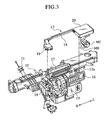
- the housing member 13 for housing wiring harnesses is arranged between the HVAC control module 12 and the steering member module 10 as shown in Fig. 3.
- the housing member 13 looks like a C-letter shape in a plan view and is integrally composed of a connector housing portion 19 at a driver's seat side, an electronic control unit housing portion 20 at a side of the assistant's seat and the wiring harness housing portion 14 therebetween.
- a plurality of connectors housed in the connector housing portion 19 are formed in a unified shape having a unified terminal alignment.
- a power bus circuit, a power of which is supplied from the electronic control units, and a superimposing communication circuit are connected to the connectors housed in the connector housing portion 19.
- Both the connector housing portion 19 and an electronic unit housing portion 20 are formed in box shapes, which look rectangular in plan view.
- the connector housing portion 19 houses a plurality of connectors for connection with the connector connection portion 18.
- the electronic control unit housing portion 20 houses electronic control units to which the connectors are connected via the wiring harnesses.
- the HVAC control module 12 is disposed between the connector housing portion 19 and the electronic control unit housing portion 20.
- the wiring harness housing portion 14 is formed narrower so as to be insertable in the space formed between the HVAC control module 12 and the steering member module 10.
- Cables 22a, 23a, 24a which are disposed at the hidden side of the instrument panel 21 at the driver's seat side, are respectively wired from the connector connection portion 18 to the steering module 22, various meters 23 and various monitors 24.
- a gearshift control unit and a sub module DM for the driver similar configurations are provided.
- the electronic control unit housing portion 20 further houses a navigation system 25 arranged at the assistant's seat side, an airbag system 26 and an electronic control unit for the HVAC control module 12 as well as the electronic control units for a plurality of units arranged at the driver's seat side.
- the electronic control units are provided with a module side connector MC connected to a connector for the automobile via a main wiring harness MH, which is arranged at the assistant seat side and connected to the outside, and a cockpit control module including a meter amplifier and an amplifier for control of the air conditioner.
- the wiring harness housing portion 14 is so dimensioned as to be insertable between the space formed between the HVAC control module 12 and the steering member module 10.
- Such the wiring harness housing portion 14 is arranged between the HVAC control module 12 and the steering member module 10, thereby small space in the vicinity of the instrument panel can be effectively utilized.
- the wiring labor becomes very troublesome.
- the plural wiring harnesses are housed in the housing member 13, which is easy to be handled, thereby wiring can be done at a time and without difficulty.
- the HVAC control module 12 occupying large space is arranged at the center of the steering module 10, the wiring harnesses can be easily wired.
- the main wiring harness MH is necessarily formed thick because the main wiring harness MH must serve a lot of connections between the electronic control units and the connectors. According to the embodiment of the present invention, the main wiring harness MH can be formed shorter, thereby the wiring labor is made easy and weight thereof is decreased.
- the connector connection portion 18 is disposed at a side surface of the HVAC control module 12 and exposed so as to be accesible, thereby electrical connections of the plural units at the driver's seat side can be centralized there and the connection labor becomes easy.
- the wiring harnesses led to the units at the driver's seat side can be connected with any positions of the connectors housed in the connector housing member 19, thereby improper connection can be prevented even if the connectors are centralized.
Landscapes
- Engineering & Computer Science (AREA)
- Mechanical Engineering (AREA)
- Connection Or Junction Boxes (AREA)
- Details Of Indoor Wiring (AREA)
- Installation Of Indoor Wiring (AREA)
- Seats For Vehicles (AREA)
- Instrument Panels (AREA)
Abstract
Description
- The present invention relates to a wiring structure using a wiring harness for an automobile.
- An instrument panel of an automobile is commonly provided with a wiring harness on a hidden side thereof. Recently, such a wiring harness is getting larger size and weight because more electric circuits are necessary to be installed. Japanese Patent No. 3166574 discloses a related art.
- In these years, large units such as a heater, a ventilator, air conditioner and the like are often installed to a steering member, which is disposed at a hidden side of the instrument panel. When such configured, there is not an enough space for the wiring harness around the steering member and the instrument panel. Furthermore, wiring the wiring harnesses one by one must be very troublesome labor.
- The present invention has been achieved in view of the above problem and is intended for providing a wiring structure, which makes wiring labor to be easy.
- According to an aspect of the present invention, A structure for wiring a wiring harness for an automobile between an electronic control unit and one or more devices, the automobile having a steering member extended from a driver's seat side of the automobile to an assistant's seat side of the automobile, a control module arranged at a center in a width direction of the steering member and an electronic control unit for controlling the devices arranged at the assistant's seat side of the steering member and a plurality of units arranged at the driver's seat side, the wiring structure is provided with a housing member including a first portion having a first connector for connection with the devices, a second portion housing the electronic control unit and a third portion being formed in a slim shape and interconnecting the first portion and the second portion, and a wiring harness housed in the third portion, the wiring harness interconnecting the first connectors and the electronic control unit, wherein the housing member is arranged along the steering member in a manner that the third portion is housed between the control module and the steering member.
- More preferably, the structure is configured so that the control module controls a heater, a ventilator, an air-conditioner and distributions doors.
- More preferably, the electronic control unit is provided with a second connector mating with the first connector, an amplifier for a meter and an air-conditioner control amplifier.
- More preferably, the first portion is provided with a plurality of first connectors for connection with the devices and the control module is arranged between the first portion and the second portion.
- More preferably, the first connectors are formed in a unified shape having a unified terminal alignment and connected with a power bus circuit and a superimposing communication circuit of the electronic control unit.
- More preferably, the third portion is so dimensioned as to be insertable in space formed between the control module and the steering member.
-
- Fig. 1 is a perspective view of a steering member and its vicinity to which a wiring structure according to an embodiment of the present invention is applied;
- Fig. 2 is an exploded perspective view of the steering member from which an HVAC control module is separated frontward;
- Fig. 3 is an exploded perspective view of the steering member from which a housing member is separated upward; and
- Fig. 4 is a schematic drawing schematically showing the wiring structure in the vicinity of the instrument panel.
-
- An embodiment of the present invention will be described hereinafter with reference to Figs. 1 - 4. Throughout the specification and the figures, directions are defined on a basis of a view point of a passenger who is regularly seated in an automobile. In the following description and the figures, an example is given where a driver's seat is on the right and an assistant's seat is on the left. However, off course, a reversed configuration can be embodied.
- Referring is now made to Fig. 1. A
steering member module 10 is arranged at a hidden side of an instrument panel (not shown in Fig. 1 but schematically shown in Fig. 4) in a manner that thesteering member module 10 crosses an inside of an automobile in a width direction thereof. Acolumn shaft module 11 is projected backward and obliquely upward from thesteering member module 10 at a driver's side. A steering wheel (not shown) will be attached to a distal end of thecolumn shaft module 11. For controlling a heater, a ventilator and an air-conditioner (HVAC hereinafter), anHVAC control module 12 is arranged at a front side of thesteering member module 10 and substantially at a center in a width direction thereof. Narrow space is formed between thesteering member module 10 and theHVAC control module 12 and ahousing member 13 and a wiringharness housing portion 14 are housed therein as will be described later. TheHVAC control module 12 is provided with distribution doors for the heater, a cooler unit and the like. - Referring is now made to Fig. 2. The
HVAC control module 12 is composed of ablower motor 15, anair inlet port 16, avent outlet port 17 and the like, which are connected to asub wiring harness 12a. Thesub wiring harness 12a is directly connected to an electronic controlunit housing portion 20 according to the present embodiment, however, thesub wiring harness 12a may be wired to a connector connection portion 18 (see Fig. 3) alternatively. - The
housing member 13 for housing wiring harnesses is arranged between theHVAC control module 12 and thesteering member module 10 as shown in Fig. 3. Thehousing member 13 looks like a C-letter shape in a plan view and is integrally composed of aconnector housing portion 19 at a driver's seat side, an electronic controlunit housing portion 20 at a side of the assistant's seat and the wiringharness housing portion 14 therebetween. A plurality of connectors housed in theconnector housing portion 19 are formed in a unified shape having a unified terminal alignment. A power bus circuit, a power of which is supplied from the electronic control units, and a superimposing communication circuit are connected to the connectors housed in theconnector housing portion 19. - Both the
connector housing portion 19 and an electronicunit housing portion 20 are formed in box shapes, which look rectangular in plan view. Theconnector housing portion 19 houses a plurality of connectors for connection with theconnector connection portion 18. The electronic controlunit housing portion 20 houses electronic control units to which the connectors are connected via the wiring harnesses. TheHVAC control module 12 is disposed between theconnector housing portion 19 and the electronic controlunit housing portion 20. - Among portions of the
housing member 13, the wiringharness housing portion 14 is formed narrower so as to be insertable in the space formed between theHVAC control module 12 and thesteering member module 10. - Referring is now made to Fig. 4.
Cables instrument panel 21 at the driver's seat side, are respectively wired from theconnector connection portion 18 to thesteering module 22,various meters 23 andvarious monitors 24. Regarding a gearshift control unit and a sub module DM for the driver, similar configurations are provided. The electronic controlunit housing portion 20 further houses anavigation system 25 arranged at the assistant's seat side, anairbag system 26 and an electronic control unit for theHVAC control module 12 as well as the electronic control units for a plurality of units arranged at the driver's seat side. - The electronic control units are provided with a module side connector MC connected to a connector for the automobile via a main wiring harness MH, which is arranged at the assistant seat side and connected to the outside, and a cockpit control module including a meter amplifier and an amplifier for control of the air conditioner.
- The aforementioned embodiment gives the following effects.
- Among portions of the
housing member 13, the wiringharness housing portion 14 is so dimensioned as to be insertable between the space formed between theHVAC control module 12 and thesteering member module 10. Such the wiringharness housing portion 14 is arranged between theHVAC control module 12 and thesteering member module 10, thereby small space in the vicinity of the instrument panel can be effectively utilized. - As mentioned above, at the driver's seat side, many units such as the
steering module 22,various monitors 24 andvarious meters 23 are arranged. Therefore it is difficult to arrange the electronic control units at the driver's seat. It is further difficult to arrange them in front of the center of thesteering member module 10, where a large unit of theHVAC control module 12 is arraged. On the other hand, enough space to arrange the electronic control units can be made at the assistant's seat side because few units such as the meters are there. According to the embodiment of the present invention, such space is utilized for wiring, thereby the wiring labor can be easily done. - Provided that plural wiring harnesses are wired one by one, the wiring labor becomes very troublesome. However, according to the embodiment of the present invention, the plural wiring harnesses are housed in the
housing member 13, which is easy to be handled, thereby wiring can be done at a time and without difficulty. - Furthermore, provided that the
HVAC control module 12 occupying large space is arranged at the center of thesteering module 10, the wiring harnesses can be easily wired. - Still furthermore, the main wiring harness MH is necessarily formed thick because the main wiring harness MH must serve a lot of connections between the electronic control units and the connectors. According to the embodiment of the present invention, the main wiring harness MH can be formed shorter, thereby the wiring labor is made easy and weight thereof is decreased.
- Additionally, the
connector connection portion 18 is disposed at a side surface of theHVAC control module 12 and exposed so as to be accesible, thereby electrical connections of the plural units at the driver's seat side can be centralized there and the connection labor becomes easy. - The wiring harnesses led to the units at the driver's seat side can be connected with any positions of the connectors housed in the
connector housing member 19, thereby improper connection can be prevented even if the connectors are centralized. - Although the invention has been described above by reference to certain embodiments of the invention, the invention is not limited to the embodiments described above. Modifications and variations of the embodiments described above will occur to those skilled in the art, in light of the above teachings.
Claims (6)
- A structure for wiring a wiring harness for an automobile between an electronic control unit and one or more devices, the automobile having a steering member extended from a driver's seat side of the automobile to an assistant's seat side of the automobile, a control module arranged at a center in a width direction of the steering member and an electronic control unit for controlling the devices arranged at the assistant's seat side of the steering member and a plurality of units arranged at the driver's seat side, the structure comprising:wherein the housing member is arranged along the steering member in a manner that the third portion is housed between the control module and the steering member.a housing member including;
a first portion having a first connector for connection with the devices;
a second portion housing the electronic control unit; and
a third portion being formed in a slim shape and interconnecting the first portion and the second portion; anda wiring harness housed in the third portion, the wiring harness interconnecting the first connectors and the electronic control unit, - The structure of claim 1, wherein the control module controls a heater, a ventilator, an air-conditioner and distribution doors.
- The structure of claim 1, wherein the electronic control unit comprises a second connector mating with the first connector, an amplifier for a meter and an air-conditioner control amplifier.
- The structure of claim 1, wherein the first portion comprises a plurality of first connectors for connection with the devices and the control module is arranged between the first portion and the second portion.
- The structure of claim 4, wherein the first connectors are formed in a unified shape having a unified terminal alignment and connected with a power bus circuit and a superimposing communication unit of the electronic control unit.
- The structure of claim 1, wherein the third portion is so dimensioned as to be insertable in space formed between the control module and the steering member.
Applications Claiming Priority (2)
| Application Number | Priority Date | Filing Date | Title |
|---|---|---|---|
| JP2002362451A JP4064804B2 (en) | 2002-12-13 | 2002-12-13 | Wiring harness wiring structure for vehicles |
| JP2002362451 | 2002-12-13 |
Publications (2)
| Publication Number | Publication Date |
|---|---|
| EP1428727A1 true EP1428727A1 (en) | 2004-06-16 |
| EP1428727B1 EP1428727B1 (en) | 2006-05-31 |
Family
ID=32322142
Family Applications (1)
| Application Number | Title | Priority Date | Filing Date |
|---|---|---|---|
| EP03028587A Expired - Lifetime EP1428727B1 (en) | 2002-12-13 | 2003-12-11 | Wiring structure using wiring harness for automobile |
Country Status (4)
| Country | Link |
|---|---|
| US (1) | US7265998B2 (en) |
| EP (1) | EP1428727B1 (en) |
| JP (1) | JP4064804B2 (en) |
| DE (1) | DE60305614T2 (en) |
Cited By (2)
| Publication number | Priority date | Publication date | Assignee | Title |
|---|---|---|---|---|
| WO2017093313A1 (en) * | 2015-12-02 | 2017-06-08 | Trw Automotive Safety Systems Gmbh | Cable conduit device for connection cables of an airbag module, wiring system, airbag module, and steering wheel or vehicle comprising a cable conduit device of said type |
| CN109501564A (en) * | 2018-11-01 | 2019-03-22 | 合肥巨动力系统有限公司 | A kind of three-in-one electric drive integrated system of new-energy automobile |
Families Citing this family (3)
| Publication number | Priority date | Publication date | Assignee | Title |
|---|---|---|---|---|
| US8924025B2 (en) * | 2011-04-28 | 2014-12-30 | GM Global Technology Operations LLC | Heating, ventilating, and air conditioning module for a vehicle |
| WO2016191662A1 (en) | 2015-05-27 | 2016-12-01 | Intelligent Technologies International, Inc. | Vehicle wire harness |
| CN110281861A (en) * | 2019-07-24 | 2019-09-27 | 广汽蔚来新能源汽车科技有限公司 | Hub, vehicle, hub control method and hub control device |
Citations (6)
| Publication number | Priority date | Publication date | Assignee | Title |
|---|---|---|---|---|
| US5364159A (en) * | 1993-06-15 | 1994-11-15 | Davidson Textron Inc. | Structural instrument panel carrier assembly |
| US5467520A (en) * | 1992-12-21 | 1995-11-21 | Chrysler Corporation | Apparatus for automatically feeding and assembling wires into a trough of a panel |
| US5549344A (en) * | 1993-04-14 | 1996-08-27 | Kansei Corporation | Structure of instrument panel portion for use in vehicles |
| US5884875A (en) * | 1995-04-26 | 1999-03-23 | Nissan Motor Co., Ltd. | Structure for mounting automotive installation and mounting method thereof |
| US20010002623A1 (en) * | 1999-12-02 | 2001-06-07 | Mitsunori Tsunoda | Steering wire harness, steering module, and wiring system of steering wire harness |
| US20010003404A1 (en) * | 1999-12-10 | 2001-06-14 | Denso Corp | Wiring system of indication instrument for vehicle |
Family Cites Families (8)
| Publication number | Priority date | Publication date | Assignee | Title |
|---|---|---|---|---|
| JPH08119045A (en) | 1994-10-21 | 1996-05-14 | Nissan Motor Co Ltd | Arrangement structure of vehicle harness |
| JPH08258642A (en) | 1995-03-23 | 1996-10-08 | Honda Motor Co Ltd | Car wiring structure |
| JP3166574B2 (en) | 1995-07-31 | 2001-05-14 | 住友電装株式会社 | Automotive wire harness |
| US5712764A (en) * | 1996-05-03 | 1998-01-27 | Ford Motor Company | Apparatus and method of assembling vehicle instrument panel structural and electronic components |
| JPH1148880A (en) * | 1997-07-31 | 1999-02-23 | Yazaki Corp | Wire harness device for instrument panel |
| JP3489665B2 (en) * | 1999-04-13 | 2004-01-26 | 矢崎総業株式会社 | Wire harness device for instrument panel |
| JP2002293166A (en) | 2001-03-30 | 2002-10-09 | Denso Corp | Vehicle-mounted structure and method of mounting strength member in instrument panel |
| US6621688B1 (en) * | 2002-06-26 | 2003-09-16 | Alcoa Fujikura Limited | Electrical distribution system having integral junction box for instrument panel application |
-
2002
- 2002-12-13 JP JP2002362451A patent/JP4064804B2/en not_active Expired - Fee Related
-
2003
- 2003-12-10 US US10/731,101 patent/US7265998B2/en not_active Expired - Fee Related
- 2003-12-11 EP EP03028587A patent/EP1428727B1/en not_active Expired - Lifetime
- 2003-12-11 DE DE60305614T patent/DE60305614T2/en not_active Expired - Fee Related
Patent Citations (6)
| Publication number | Priority date | Publication date | Assignee | Title |
|---|---|---|---|---|
| US5467520A (en) * | 1992-12-21 | 1995-11-21 | Chrysler Corporation | Apparatus for automatically feeding and assembling wires into a trough of a panel |
| US5549344A (en) * | 1993-04-14 | 1996-08-27 | Kansei Corporation | Structure of instrument panel portion for use in vehicles |
| US5364159A (en) * | 1993-06-15 | 1994-11-15 | Davidson Textron Inc. | Structural instrument panel carrier assembly |
| US5884875A (en) * | 1995-04-26 | 1999-03-23 | Nissan Motor Co., Ltd. | Structure for mounting automotive installation and mounting method thereof |
| US20010002623A1 (en) * | 1999-12-02 | 2001-06-07 | Mitsunori Tsunoda | Steering wire harness, steering module, and wiring system of steering wire harness |
| US20010003404A1 (en) * | 1999-12-10 | 2001-06-14 | Denso Corp | Wiring system of indication instrument for vehicle |
Cited By (2)
| Publication number | Priority date | Publication date | Assignee | Title |
|---|---|---|---|---|
| WO2017093313A1 (en) * | 2015-12-02 | 2017-06-08 | Trw Automotive Safety Systems Gmbh | Cable conduit device for connection cables of an airbag module, wiring system, airbag module, and steering wheel or vehicle comprising a cable conduit device of said type |
| CN109501564A (en) * | 2018-11-01 | 2019-03-22 | 合肥巨动力系统有限公司 | A kind of three-in-one electric drive integrated system of new-energy automobile |
Also Published As
| Publication number | Publication date |
|---|---|
| DE60305614T2 (en) | 2006-09-21 |
| JP2004189181A (en) | 2004-07-08 |
| EP1428727B1 (en) | 2006-05-31 |
| DE60305614D1 (en) | 2006-07-06 |
| JP4064804B2 (en) | 2008-03-19 |
| US20040124706A1 (en) | 2004-07-01 |
| US7265998B2 (en) | 2007-09-04 |
Similar Documents
| Publication | Publication Date | Title |
|---|---|---|
| US7137823B2 (en) | Apparatus equipped with electronic control units | |
| US6048020A (en) | Electrical interconnection module for vehicle instrument panel | |
| US5883777A (en) | Meter module and structure for assembling the same | |
| US6249425B1 (en) | Wiring structure for instrument panel of vehicle | |
| US5502615A (en) | Meter module assembly | |
| GB2382058A (en) | Instrument panel with non-contact power and signal transmission between control units and visible display/switches. | |
| EP1428727B1 (en) | Wiring structure using wiring harness for automobile | |
| JP5692897B2 (en) | Electrical system | |
| JP2019196052A (en) | Wiring harness, component module for wiring harness, and vehicle component | |
| US6108905A (en) | Method and structure for assembling meter modules to vehicles | |
| US6455950B1 (en) | Circuit connection structure of automobile door | |
| JPH07257233A (en) | Meter module assembly | |
| JP2926674B2 (en) | Meter module and its connection device | |
| JP2000190755A (en) | Instrument panel | |
| CN115123399B (en) | Vehicle structure | |
| JPH11255000A (en) | instrument panel | |
| US20020094714A1 (en) | Vehicle air-conditioning module | |
| JP3627210B2 (en) | Meter module | |
| JP4379667B2 (en) | instrument panel | |
| JP3636969B2 (en) | Wiring connection structure of vehicle air conditioning unit | |
| JP2001138832A (en) | Wiring method for vehicle air conditioner, wire harness therefor, and control system for air conditioner | |
| JPH11139181A (en) | Instrument panel reinforcement | |
| JPH10194060A (en) | Centrally located electrical junction box | |
| JP2001315591A (en) | Assembly structure of in-vehicle electronic devices | |
| JP2006069480A (en) | Open air introducing structure of automobile |
Legal Events
| Date | Code | Title | Description |
|---|---|---|---|
| PUAI | Public reference made under article 153(3) epc to a published international application that has entered the european phase |
Free format text: ORIGINAL CODE: 0009012 |
|
| AK | Designated contracting states |
Kind code of ref document: A1 Designated state(s): AT BE BG CH CY CZ DE DK EE ES FI FR GB GR HU IE IT LI LU MC NL PT RO SE SI SK TR |
|
| AX | Request for extension of the european patent |
Extension state: AL LT LV MK |
|
| 17P | Request for examination filed |
Effective date: 20040827 |
|
| AKX | Designation fees paid |
Designated state(s): DE FR GB |
|
| GRAP | Despatch of communication of intention to grant a patent |
Free format text: ORIGINAL CODE: EPIDOSNIGR1 |
|
| GRAS | Grant fee paid |
Free format text: ORIGINAL CODE: EPIDOSNIGR3 |
|
| GRAA | (expected) grant |
Free format text: ORIGINAL CODE: 0009210 |
|
| AK | Designated contracting states |
Kind code of ref document: B1 Designated state(s): DE FR GB |
|
| REG | Reference to a national code |
Ref country code: GB Ref legal event code: FG4D |
|
| REF | Corresponds to: |
Ref document number: 60305614 Country of ref document: DE Date of ref document: 20060706 Kind code of ref document: P |
|
| ET | Fr: translation filed | ||
| PLBE | No opposition filed within time limit |
Free format text: ORIGINAL CODE: 0009261 |
|
| STAA | Information on the status of an ep patent application or granted ep patent |
Free format text: STATUS: NO OPPOSITION FILED WITHIN TIME LIMIT |
|
| 26N | No opposition filed |
Effective date: 20070301 |
|
| PGFP | Annual fee paid to national office [announced via postgrant information from national office to epo] |
Ref country code: FR Payment date: 20081212 Year of fee payment: 6 |
|
| PGFP | Annual fee paid to national office [announced via postgrant information from national office to epo] |
Ref country code: DE Payment date: 20081205 Year of fee payment: 6 |
|
| PGFP | Annual fee paid to national office [announced via postgrant information from national office to epo] |
Ref country code: GB Payment date: 20081210 Year of fee payment: 6 |
|
| REG | Reference to a national code |
Ref country code: GB Ref legal event code: 746 Effective date: 20090924 |
|
| GBPC | Gb: european patent ceased through non-payment of renewal fee |
Effective date: 20091211 |
|
| REG | Reference to a national code |
Ref country code: FR Ref legal event code: ST Effective date: 20100831 |
|
| PG25 | Lapsed in a contracting state [announced via postgrant information from national office to epo] |
Ref country code: FR Free format text: LAPSE BECAUSE OF NON-PAYMENT OF DUE FEES Effective date: 20091231 |
|
| PG25 | Lapsed in a contracting state [announced via postgrant information from national office to epo] |
Ref country code: DE Free format text: LAPSE BECAUSE OF NON-PAYMENT OF DUE FEES Effective date: 20100701 |
|
| PG25 | Lapsed in a contracting state [announced via postgrant information from national office to epo] |
Ref country code: GB Free format text: LAPSE BECAUSE OF NON-PAYMENT OF DUE FEES Effective date: 20091211 |