EP1428643A2 - Dispositif d'emballage isotherme et procédé de fabrication - Google Patents
Dispositif d'emballage isotherme et procédé de fabrication Download PDFInfo
- Publication number
- EP1428643A2 EP1428643A2 EP03293037A EP03293037A EP1428643A2 EP 1428643 A2 EP1428643 A2 EP 1428643A2 EP 03293037 A EP03293037 A EP 03293037A EP 03293037 A EP03293037 A EP 03293037A EP 1428643 A2 EP1428643 A2 EP 1428643A2
- Authority
- EP
- European Patent Office
- Prior art keywords
- volume
- cover
- container
- envelope
- enclosure
- Prior art date
- Legal status (The legal status is an assumption and is not a legal conclusion. Google has not performed a legal analysis and makes no representation as to the accuracy of the status listed.)
- Granted
Links
Images


Classifications
-
- B—PERFORMING OPERATIONS; TRANSPORTING
- B29—WORKING OF PLASTICS; WORKING OF SUBSTANCES IN A PLASTIC STATE IN GENERAL
- B29C—SHAPING OR JOINING OF PLASTICS; SHAPING OF MATERIAL IN A PLASTIC STATE, NOT OTHERWISE PROVIDED FOR; AFTER-TREATMENT OF THE SHAPED PRODUCTS, e.g. REPAIRING
- B29C44/00—Shaping by internal pressure generated in the material, e.g. swelling or foaming ; Producing porous or cellular expanded plastics articles
- B29C44/02—Shaping by internal pressure generated in the material, e.g. swelling or foaming ; Producing porous or cellular expanded plastics articles for articles of definite length, i.e. discrete articles
- B29C44/12—Incorporating or moulding on preformed parts, e.g. inserts or reinforcements
- B29C44/1228—Joining preformed parts by the expanding material
- B29C44/1233—Joining preformed parts by the expanding material the preformed parts being supported during expanding
-
- B—PERFORMING OPERATIONS; TRANSPORTING
- B31—MAKING ARTICLES OF PAPER, CARDBOARD OR MATERIAL WORKED IN A MANNER ANALOGOUS TO PAPER; WORKING PAPER, CARDBOARD OR MATERIAL WORKED IN A MANNER ANALOGOUS TO PAPER
- B31B—MAKING CONTAINERS OF PAPER, CARDBOARD OR MATERIAL WORKED IN A MANNER ANALOGOUS TO PAPER
- B31B2105/00—Rigid or semi-rigid containers made by assembling separate sheets, blanks or webs
- B31B2105/002—Making boxes characterised by the shape of the blanks from which they are formed
-
- B—PERFORMING OPERATIONS; TRANSPORTING
- B31—MAKING ARTICLES OF PAPER, CARDBOARD OR MATERIAL WORKED IN A MANNER ANALOGOUS TO PAPER; WORKING PAPER, CARDBOARD OR MATERIAL WORKED IN A MANNER ANALOGOUS TO PAPER
- B31B—MAKING CONTAINERS OF PAPER, CARDBOARD OR MATERIAL WORKED IN A MANNER ANALOGOUS TO PAPER
- B31B2120/00—Construction of rigid or semi-rigid containers
- B31B2120/40—Construction of rigid or semi-rigid containers lined or internally reinforced
-
- B—PERFORMING OPERATIONS; TRANSPORTING
- B65—CONVEYING; PACKING; STORING; HANDLING THIN OR FILAMENTARY MATERIAL
- B65D—CONTAINERS FOR STORAGE OR TRANSPORT OF ARTICLES OR MATERIALS, e.g. BAGS, BARRELS, BOTTLES, BOXES, CANS, CARTONS, CRATES, DRUMS, JARS, TANKS, HOPPERS, FORWARDING CONTAINERS; ACCESSORIES, CLOSURES, OR FITTINGS THEREFOR; PACKAGING ELEMENTS; PACKAGES
- B65D81/00—Containers, packaging elements, or packages, for contents presenting particular transport or storage problems, or adapted to be used for non-packaging purposes after removal of contents
- B65D81/38—Containers, packaging elements, or packages, for contents presenting particular transport or storage problems, or adapted to be used for non-packaging purposes after removal of contents with thermal insulation
- B65D81/3848—Containers, packaging elements, or packages, for contents presenting particular transport or storage problems, or adapted to be used for non-packaging purposes after removal of contents with thermal insulation semi-rigid container folded up from one or more blanks
- B65D81/3858—Containers, packaging elements, or packages, for contents presenting particular transport or storage problems, or adapted to be used for non-packaging purposes after removal of contents with thermal insulation semi-rigid container folded up from one or more blanks formed of different materials, e.g. laminated or foam filling between walls
Definitions
- the present invention relates to the field of packaging isotherms.
- the invention relates more particularly to a device isothermal packaging for heat-sensitive products, materials dangerous, infectious, biologically active products, etc. used especially in biotechnology, chemistry, pharmacy or any other type of product tolerating only a very small temperature variation.
- the object of the present invention is therefore to alleviate one or more of the disadvantages of the prior art by defining a reliable and industrial process manufacturing an insulated packaging device which allows injection, at inside this device, a high density polyurethane foam under high pressure with increased thermal insulation performance.
- the method according to the invention comprises a demolding of said container, said cover being removable and suitable for said container.
- said inner envelope is shaped to form the bottom and walls of a housing open to the interior of said container, said outer envelope being shaped to forming the outer bottom and the outer walls of said container, said housing being tightly closed by means of a plug re-entering thermally insulating seal of the cover.
- the method according to the invention comprises a step of cutting said sealing ring and a step of using the central part of this cutting to constitute said re-entrant sealing cap forming the base of said cover, the walls exterior of said cover being held by folding a sheet, the internal volume thus delimited being filled with polyurethane foam under high pressure injected before positioning the re-entrant plug and closure of a second external conformation enclosure enclosing said cover during the expansion of the foam thus injected.
- the volume of polyurethane foam injected inside the cover is calculated according to said internal volume to be filled and the final density of foam desired.
- the inner envelopes and outer of the container each have a sheet cut out of cardboard or packaging material with similar properties, folded and glued to form a regular volume with a horizontal bottom and vertical walls, folding the inner envelope (10) having overlaps removing any point foam leakage potential on the edges of the interior bottom.
- the bottom of said housing is rectangular and formed by successive folding of a first flap covering at minus the entire bottom, of two flaps adjacent to said first flap, then a last flap with an insertion tab under said two flaps adjacent.
- said container is placed in the inverted position on said shaping mold, said mold being fixed and comprising a base on which the sealing ring is placed, said first enclosure being movable and having walls dimensionally stable.
- said first enclosure mounted sliding on rails, comprises at least two movable walls around a axis closing on said outer casing and fixing means in closed position of said movable walls, closing of said walls mobile being carried out before the expansion of the polyurethane foam so that the covering of said external envelope by said first pregnant is total.
- the second outer enclosure of conformation comprises at least two movable partitions around an axis se closing on the cover and fixing means in the closed position of said movable partitions, the closing of said movable partitions being performed before the expansion of the polyurethane foam so that the covering of the cover by said second enclosure is total.
- said container is parallelepiped and the bottom of said outer envelope is formed by at least two flaps, said injection of polyurethane foam being followed at least by the closing of a movable wall of said first shaping enclosure for folding said flaps from the bottom of the outer envelope into position horizontal.
- said mold is made of wood, metal or alloy resistant.
- said first and second enclosures conformation include metallic materials or wood.
- An objective of the invention is also to define a device affordable insulated packaging with foam high density polyurethane insulation injected under high pressure.
- said density obtained by free expansion is of the order of 31 kg / m 3
- said polyurethane monoblock having a density of between 38 and 51 kg / m 3 .
- said re-entrant plug and said crown seals have a thickness between 5 and 20 mm, and are made of polyolefin foam.
- the inner envelope (10), the envelope outer (11) and said cover sheet (20) each have cardboard or packaging material with similar properties, of a thickness between 0.5 and 10 mm.
- the inner and outer envelopes of the container each have a single sheet cut from cardboard or extruded plastic, folded and glued to form a regular volume at the bottom horizontal and vertical walls.
- the bottom of the inner envelope forming said housing is rectangular and comprises, from top to bottom, a first flap covering at least the entire bottom, two flaps adjacent to said first flap and a last flap with an insertion tab under said two adjacent flaps.
- the outer envelope of the container is formed in one piece from a single rectangular strip divided into a row of four foldable parts to constitute in particular the four outer walls of the container, these four foldable parts each having upper and lower flaps for closing respectively the top and bottom of the container, the height of the external envelope being sufficient for the cover to be inserted under said upper flaps.
- said cover sheet is formed in one piece from a rectangular strip secured with flaps, said rectangular strip forming the top of the cover, the flaps forming the other walls and each having an end which bends above said re-entrant sealing cap, at least one of said flaps comprising additional foldable intermediate portions to form a tongue gripping the cover.
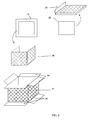
- the isothermal packaging device consists of a container (1) and a cover (2).
- the cover (2) is for example removable and may include a gripping tab (21) to facilitate the opening of the device.
- the container (1) and the cover (2) each comprise a monobloc layer of polyurethane foam sandwiched between two walls.
- the density of the polyurethane foam reaches a value of between 38 and 51 kg / m 3 , this value being reached by over-densification of the polyurethane foam injected under high pressure.
- the various walls of the cover (2) and of the container (1) are for example made of cardboard. The thickness of these walls can vary between 0.5 and 10 mm.
- Other packaging materials with similar properties can be envisaged in place of cardboard, for example paper, a polyolefin such as polyethylene or polypropylene or any other unexpanded plastic material obtained by extrusion.
- the container comprises an inner envelope (10) and an outer envelope (11) of cardboard, the polyurethane foam being interposed between these two envelopes (10, 11).
- the inner envelope (10) is shaped to form the bottom and the inner walls of a housing (L) intended to receive one or more products to be kept at constant temperature.
- the outer envelope (11) forms in particular the outer bottom and the outer walls of the container (1).
- the inner casing (10) is rectangular and has a rectangular opening on the top.
- a sealing ring with thermal insulation properties consisting for example of a polyolefin foam or other synthetic material with similar properties, borders the opening of the inner envelope (10).
- This sealing ring has a determined width for closing the peripheral volume (V1) located between the inner envelope (10) and the outer envelope (11) of the container (1).
- Said peripheral volume (V1) is completely filled with polyurethane foam.
- This foam has a closed cell structure and has a very efficient thermal insulation coefficient of around 0.021 K / (mK). The density of this foam, from 38 to 51 kg / m 3 , is greater than the density obtained by free expansion which amounts to approximately 31 kg / m 3 .
- the inner envelope (10) can form a non-parallelepiped housing (L).
- the opening of the housing (L) can obviously have a different shape, adapted to the type of product to be stored at constant temperature.
- the cover (2) is formed by a sheet (20) of cardboard or the like formable packaging material and a tight seal positioned at the base of said cover (2), as illustrated in FIG. 2.
- This waterproof seal made of the same type of material that for the sealing ring (12), constitutes a re-entrant plug (22) in the opening of the housing (L).
- said re-entrant plug (22) is obtained during the cutting of said crown sealing (12).
- the insulating material making up the sealing ring (12) and the re-entrant plug (22) is for example a foam of flexible polyethylene, thickness between 5 and 20 mm.
- This foam polyethylene can be colored blue or any other color.
- the sticky properties of polyurethane foam make the joints seal (12, 22) used in the container (1) and the cover (2) adhere to the polyurethane foam monoblock.
- the thickness of the external envelope (11) can be of the order of 2 mm while the thickness of the inner envelope (10) and said sheet of the cover (2) is of the order of 1 mm.
- the cover (2) has a thickness corresponding substantially to the excess height (H) of the outer casing (11) relative to the level of the sealing ring (12) bordering the opening of the housing (L).
- the cover (2) can thus be covered by upper flaps (14) of the outer casing (11) of the container (1).
- the outer casing (11) can be devoid of upper flaps (14).
- the cover (2) can be attached to the container (1) by fasteners of a known type. These fixings are then mounted on the side of the outer casing (11) so as to maintain a very high thermal insulation.
- the manufacture of the container (1) involves a first conformation enclosure (6) serving to hold the external envelope (11) and to contain the thrust of the polyurethane foam, as illustrated diagrammatically in FIG. 3.
- a interior shaping mold (5) is also used to maintain the interior envelope (10) as well as the sealing crown (12) and contain the thrust of the foam during expansion.
- the mold (5) comprises a head (51) mounted on a base (52).
- This head (1) has a volume substantially equal to the volume of said housing (L).
- the sealing ring (12) can be placed on the base (52) and wedged by the inner casing (10) positioned on the mold head (51).
- the mold head corresponds to a parallelepiped or to another regular volume.
- said first enclosure (6) is positioned against the outer casing (11), movable walls (61, 62) of this enclosure (6) sealingly closing on the top and on one side of the container (1) during manufacture.
- the inner (10) and outer (11) envelopes can be formed each of a single sheet cut from usual packaging material, folded and possibly glued.
- the regular volume formed by the inner envelope (10) must not contain any leaks, in particular at the level of the folds between the horizontal bottom and vertical walls.
- Figure 6 shows an example of a cardboard part or material similar packaging to be shaped to constitute the envelope interior (10).
- the bottom of the envelope interior (10) is rectangular and comprises, from top to bottom, a first flap (100) covering at least the entire bottom, two flaps (102) adjacent to said first flap (100) and a last flap (103) having a insertion tongue (104) under said two adjacent flaps (102).
- a folding of this type of the various flaps (100, 101, 102, 103) of the envelope inner (10) to form the bottom allows to effectively fill the points leakage that can be generated in the bottom edges, so that sealing is ensured.
- the folding of the inner envelope (10) comprises thus one or more overlaps at the bottom edges.
- the outer envelope (11) can be formed integrally from a single rectangular strip divided into a row of four parts foldable (111, 112, 113, 114) to constitute in particular the four walls container (1). Said four foldable parts (111, 112, 113, 114) each have upper (14) and lower (13) flaps to close the top and bottom of the container (1) respectively.
- the outer casing (11) can be closed by gluing a tab collage (110). The same can be said for the inner envelope (10), for example through a bonding strip (105). Other embodiments analogues are naturally conceivable for said envelopes (10, 11).
- a facing can be added inside the interior envelope (10) and / or outside the outer envelope (11).
- FIG. 5 represents an example of a sheet (20) of cardboard or similar packaging material to be shaped to constitute the cover coating (2).
- Said sheet (20) of the cover (2) is formed in one piece from a rectangular strip (200) integral with flaps (201). This rectangular strip (200) forms the top of the cover (2) and the flaps form the other walls.
- the end of the flaps comes, by folding, to be inserted on top of the stopper re-sealing (22).
- At least one of said flaps has portions additional intermediate folds (202) to form a tongue (21) or a handle for gripping the cover (2).
- the injection of the polyurethane mouse is carried out using an injection gun (4) or an equivalent known injector means.
- the polyalcohol and isocyanate precursors are pressurized in suitable containers (3) to then be mixed and injected so as to form the polyurethane foam.
- the gas used for expansion is for example air or other gas / gas mixture for expansion known to those skilled in the art.
- the container (1) can be returned to the inverted position, as shown in Figures 7 and 8 when injecting the foam.
- the polyurethane is liquid when it leaves the injector gun (4) and remains in this state for a determined period of time, of the order of about twenty seconds. It is applied to the bottom of the inverted volume (V1) to be filled.
- the exothermic reaction starts and the foam swells with a pressure of approximately 1 kg / cm 2 , so that it completely fills the peripheral volume (V1) of the container (1).
- the initial injection volume is naturally calibrated to obtain this filling with a foam density of the order of 38 to 51 kg / m 3 in the preferred embodiment of the invention.
- the envelope outer (11) is shaped to form the outer bottom, the walls outside and possibly the top of the container (1).
- a box classic exterior for example of the American envelope type or full color envelope, can be considered as an external envelope (11).
- the container (1) parallelepiped has an outer bottom formed by at least two flaps (13).
- the injection of polyurethane foam is followed by the closing of a wall mobile (61) of the shaping enclosure (6) for folding said flaps (13) of the bottom of the outer casing (11) in a horizontal position.
- the crown sealing (12) is arranged, before injection leading to the expansion of polyurethane foam, between the mold (5) and the edge of the walls of said housing (L) to constitute a closing element of the volume (V1) peripheral between the inner envelope (10) and the outer envelope container (1).
- the mold interior (5) is made of wood, metal or resistant alloy and the exterior enclosure (6) conformation includes metallic materials or wood or a combination of these materials.
- the external conformation enclosure (6) adapted to the volume of the external envelope (11), contains the foam and prevents leakage of this foam. Due to its elasticity, the foam is thus sandwiched and fills the entire peripheral volume (V1) to form a monoblock.
- the manufacturing process of the cover (2) involves a conformation enclosure (7) adapting to the shape of the cover (2).
- the enclosure (7) for shaping the cover (2) can completely wrap the cover (2).
- the seal forming the re-entrant plug (22) of the cover (2) is wedged between the walls of the enclosure (7) and the folded sheet (20) of the cover (2).
- This seal is affixed after injection of the foam into the internal volume (V2) of the cover formed by the sheet (20).
- At least one movable partition of the conformation enclosure (7) is then closed before the start of foam expansion so that said enclosure (7) contains substantially uniformly the thrust of the foam.
- Use a single sheet (20) of cardboard or the like is economical and allows to avoid leaks in the corners.
- the cover (2) can also be formed by an assembly of several sheets overlapping at less partially and does not generate such leaks.
- This simple manufacturing process can be adapted to different housing shapes and different sizes for the outer casing (11). he it is indeed easy to simply change the interior shaping mold. In addition it is easy to choose different thicknesses of cardboard or another usual packaging material, a small thickness of the order of a millimeter may be suitable for this process.
- the inner mold (5) for the container (1) is fixed while the enclosure (6) for shaping the container (1) is mobile, as illustrated in Figure 9.
- This first (6) conforming enclosure for example mounted sliding on rails by intermediate pads, comprises at least two movable walls (61, 62) around an axis and closing on the outer envelope (11) of the container (1).
- the movable walls (61, 62) can for example be articulated around hinge elements (64).
- This enclosure (6) comprises a structure may be formed by metal profiles and panels of a sufficient thickness to be non-deformable, for example of the order of 2 mm in the case of aluminum-based panels.
- the enclosure (6) comprises fixing means (63) in the closed position of said movable walls (61, 62).
- the closing of the movable walls (61, 62) can thus be carried out before expanding the polyurethane foam so that the covering of said external envelope (11) by the enclosure (6) is total.
- this enclosure can be movable by rolling, for example on rollers, or brought vertically on the mold (5) and the container (1) by a lifting system.
- the second conforming enclosure (7) used for the cover similarly comprises at least two partitions mobile (not shown) around an axis and closing on the cover (2). It can be fixed and also includes fixing means in the closed position of the movable partitions, so that the covering of the cover (2) by this second enclosure (7) is total.
- any upper flaps (14) of the envelope outer (11) are folded on the outside along the outer walls (111, 112, 113, 114) lateral.
- the gripping tab (21) is folded against the outer walls of the cover when closing the corresponding conformation enclosure (7).
- the lower flaps (13) of the outer envelope (11) can be four, the cutting of these flaps (13) being such that the expanding foam can adhere and stick to each of these flaps (13).
- One of the advantages of the invention lies in the simplicity of manufacture of the isothermal packaging device.
- the manufacturing process can be easily industrialized, the shape of the housing (L) can be very easily modified.
- the use of cardboard or other envelopes usual thin packaging material and therefore low weight is economically advantageous.
- Another advantage of the invention lies in the fact that with a high density polyurethane monoblock foam, for example amounting to 38 to 51 kg / m 3 , the insulation performance is considerably increased.
- the thermally insulating monobloc completely envelops the housing (L) and there is no thermal bridge despite the use of a material as light as cardboard.
- the invention therefore provides an optimized solution for packaging heat-sensitive products. Compared to known packaging, the manufacturing process provides a packaging device with a high-performance thermal insulation coefficient.
- An additional advantage of the invention is that the method, which can be easily industrialized, particularly suitable for responding to mass production requirements.
Landscapes
- Packages (AREA)
- Laminated Bodies (AREA)
- Cartons (AREA)
- Making Paper Articles (AREA)
- Casting Or Compression Moulding Of Plastics Or The Like (AREA)
- Solid-Sorbent Or Filter-Aiding Compositions (AREA)
Abstract
Description
- mise en volume d'une enveloppe intérieure ayant une face ouverte à une extrémité,
- mise en volume d'une enveloppe externe ouverte aux deux extrémités et comportant des rabats,
- mise en place, sur un moule intérieur de mise en forme, de l'enveloppe intérieure préalablement mise en volume,
- mise en place sur la surface du moule adjacente à l'ouverture de l'enveloppe intérieure d'une couronne d'étanchéité thermiquement isolante,
- mise en place de ladite enveloppe externe autour de ladite couronne d'étanchéité,
- mise en place d'une première enceinte extérieure de conformation venant entourer l'enveloppe externe,
- injection d'un volume déterminé de mousse de polyuréthane sous haute pression dans le volume dit périphérique formé entre l'enveloppe intérieure et l'enveloppe externe, ledit volume de mousse étant calculé en fonction dudit volume périphérique et de la densité finale de mousse souhaitée,
- fermeture dudit volume périphérique par les rabats de l'enveloppe externe situés du côté opposé à l'ouverture de l'enveloppe intérieure et fermeture de ladite première enceinte,
- expansion de la mousse dans ledit volume périphérique.
- la mise en volume par pliage d'une feuille carton ou matériau d'emballage analogue, le volume formé par cette feuille carton correspondant sensiblement au volume dudit couvercle,
- le positionnement de ladite feuille dans une seconde enceinte extérieure de conformation de volume déterminé pour envelopper le couvercle,
- le positionnement d'au moins un élément d'étanchéité, situé à la base dudit couvercle, dont la forme correspond à l'ouverture entre les parois intérieures dudit contenant pour constituer un bouchon rentrant d'étanchéité,
- une injection d'un volume déterminé de mousse de polyuréthane sous haute pression dans le volume intérieur du couvercle,
- la fermeture totale et étanche de ladite seconde l'enceinte à la suite de l'injection,
- l'ouverture de ladite seconde l'enceinte après un temps suffisant pour que l'expansion de la mousse de polyuréthane remplisse le volume intérieur du couvercle délimité par ledit élément d'étanchéité et ladite feuille carton.
- la mise en volume de ladite enveloppe intérieure à partir d'une première pièce en matériau d'emballage façonnable, le volume formé par l'enveloppe intérieure correspondant sensiblement au volume d'une tête du moule de mise en forme, ledit moule comprenant un socle solidaire de ladite tête,
- le positionnement retourné de ladite enveloppe intérieure sur la tête du moule de mise en forme,
- l'insertion de la couronne d'étanchéité entre le socle du moule et la bordure des parois dudit logement,
- le positionnement retourné de ladite enveloppe externe autour du socle et de la tête dudit moule, ladite enveloppe externe étant obtenue à partir d'une deuxième pièce en matériau d'emballage façonnable, ledit fond extérieur n'étant pas encore formé,
- l'avancée de ladite première enceinte pour encercler ladite enveloppe externe,
- une injection d'un volume déterminé de mousse de polyuréthane sous haute pression dans ledit volume périphérique,
- la fermeture totale et étanche de ladite première enceinte à la suite de l'injection, ledit fond extérieur de l'enveloppe externe étant formé lors du rabattement d'au moins une paroi mobile de ladite première enceinte,
- l'ouverture puis le retrait de ladite première enceinte après un temps suffisant pour que l'expansion de la mousse de polyuréthane remplisse ledit volume périphérique,
- démoulage du contenant.
- une enveloppe intérieure conformée pour former le fond et les parois intérieures d'un logement,
- une couche monobloc de mousse polyuréthane, de densité supérieure à la densité obtenue par expansion libre, adhérant au fond et aux parois dudit logement,
- une couronne d'étanchéité thermiquement isolante recouvrant la bordure des parois du logement et ladite couche de mousse polyuréthane,
- une enveloppe externe, comportant des rabats, recouvrant au moins ladite couche de mousse polyuréthane et entourant ladite couronne d'étanchéité, ladite couche de mousse polyuréthane adhérant à l'enveloppe externe.
- un joint étanche thermiquement isolant de dimensions correspondant à la forme de l'ouverture entre les parois intérieures du logement pour constituer un bouchon rentrant d'étanchéité,
- une feuille conformée pour former le volume du couvercle,
- une couche monobloc de mousse polyuréthane, de densité supérieure à la densité obtenue par expansion libre, injectée dans le volume intérieur formé par ladite feuille et adhérant à la fois audit bouchon rentrant et à ladite feuille.
- la figure 1 représente une vue en perspective d'un mode de réalisation du dispositif d'emballage isotherme selon la présente invention,
- la figure 2 présente une vue éclatée de différents éléments constitutifs d'un dispositif d'emballage isotherme selon l'invention,
- la figure 3 représente schématiquement un moule intérieur de mise en forme et un conformateur servant à la fabrication du dispositif selon l'invention,
- la figure 4 représente un exemple de pièce de carton pouvant être utilisée pour former l'enveloppe externe du contenant,
- la figure 5 représente un exemple de pièce de carton pouvant être utilisée pour former les parois du couvercle,
- la figure 6 représente un exemple de pièce de carton pouvant être utilisée pour former l'enveloppe intérieure du contenant,
- la figure 7 représente de manière schématique l'étape d'injection de la mousse de polyuréthane dans le volume périphérique du contenant,
- les figures 8A et 8B représentent de manière schématique l'étape d'expansion de la mousse de polyuréthane dans le volume périphérique du contenant, respectivement dans le volume intérieur du couvercle,
- la figure 9 représente un exemple de structure de conformateur utilisé dans l'invention.
- mise en volume de l'enveloppe intérieure (10), le volume formé par cette enveloppe intérieure (10) correspondant au volume de la tête (51) de moule,
- positionnement renversé de ladite enveloppe intérieure (10) sur la tête (51) de moule,
- insertion de la couronne d'étanchéité (12) entre le socle (52) du moule (5) et la bordure des parois intérieures,
- positionnement renversé de ladite enveloppe externe (11) autour du socle (52) et de la tête (51) de moule, le fond extérieur du contenant (1) n'étant pas encore formé,
- avancée de ladite première enceinte (6) mobile pour encercler ladite enveloppe externe (11),
- injection de la mousse de polyuréthane sous haute pression dans ledit volume périphérique (V1) du contenant (1),
- fermeture totale et étanche de ladite première enceinte (6), le fond extérieur du contenant (1) étant formé lors du rabattement d'au moins une paroi mobile (61) de ladite première enceinte (6),
- l'ouverture puis le retrait de ladite première enceinte (6) après un temps suffisant pour que l'expansion de la mousse de polyuréthane remplisse ledit volume périphérique (V1),
- démoulage du contenant (1).
- mise en volume par pliage d'une feuille carton ou analogue (20), le volume interne (V2) formé par cette feuille (20) correspondant sensiblement au volume dudit couvercle (2),
- positionnement de ladite feuille (20) dans une seconde enceinte (7) extérieure de conformation de volume déterminé pour envelopper ledit couvercle (2),
- positionnement d'au moins un élément d'étanchéité, situé à la base dudit couvercle (2), pour constituer un bouchon rentrant d'étanchéité (22),
- injection de la mousse de polyuréthane sous haute pression dans le volume intérieur (V2) du couvercle (2),
- fermeture totale et étanche de ladite seconde l'enceinte (7),
- ouverture de ladite seconde l'enceinte (7) après un temps suffisant pour que l'expansion de la mousse de polyuréthane remplisse ledit volume intérieur (V2).
Claims (24)
- Procédé de fabrication d'un dispositif d'emballage isotherme formé d'un contenant (1) et d'un couvercle (2), comprenant une phase d'injection d'une mousse de polyuréthane dans ledit contenant (1), caractérisé en ce qu'il comporte les étapes suivantes :mise en volume d'une enveloppe intérieure (10) ayant une face ouverte à une extrémité,mise en volume d'une enveloppe externe (11) ouverte aux deux extrémités et comportant des rabats (13, 14),mise en place sur un moule intérieur de mise en forme (5) de l'enveloppe intérieure (10) préalablement mise en volume,mise en place sur la surface du moule adjacente à l'ouverture de l'enveloppe intérieure (10) d'une couronne d'étanchéité (12) thermiquement isolante,mise en place de ladite enveloppe externe (11) autour de ladite couronne d'étanchéité (12),mise en place d'une première enceinte (6) extérieure de conformation venant entourer l'enveloppe externe (11),injection d'un volume déterminé de mousse de polyuréthane sous haute pression dans le volume dit périphérique (V1) formé entre l'enveloppe intérieure (10) et l'enveloppe externe (11), ledit volume de mousse étant calculé en fonction dudit volume périphérique (V1) et de la densité finale de mousse souhaitée,fermeture dudit volume périphérique (V1) par les rabats (13) de l'enveloppe externe (11) situés du côté opposé à l'ouverture de l'enveloppe intérieure (10) et fermeture de ladite première enceinte (6),expansion de la mousse dans ledit volume périphérique (V1).
- Procédé selon la revendication 1, caractérisé en ce qu'il comporte un démoulage dudit contenant (1), ledit couvercle (2) étant amovible et adapté audit contenant (1).
- Procédé selon la revendication 1 ou 2, dans lequel ladite enveloppe intérieure (10) est conformée pour former le fond et les parois d'un logement (L) ouvert à l'intérieur dudit contenant (1), ladite enveloppe externe (11) étant conformée pour former le fond extérieur et les parois extérieures dudit contenant (1), l'ouverture dudit logement (L) étant fermée de manière étanche par l'intermédiaire d'un bouchon rentrant d'étanchéité (22) thermiquement isolant du couvercle (2).
- Procédé selon l'une quelconque des revendications 1 à 3, caractérisé en ce qu'il comprend une étape de découpe de ladite couronne d'étanchéité (12) et une étape d'utilisation de la partie centrale de ce découpage pour constituer ledit bouchon rentrant d'étanchéité (22) formant la base dudit couvercle (2), les parois extérieures dudit couvercle (2) étant tenues par un pliage d'une feuille (20), le volume interne (V2) ainsi délimité étant rempli de mousse de polyuréthane sous haute pression injectée avant positionnement dudit bouchon rentrant (22) et fermeture d'une seconde enceinte (7) extérieure de conformation enfermant ledit couvercle (2) lors de l'expansion de la mousse ainsi injectée.
- Procédé selon l'une quelconque des revendications 1 à 4, dans lequel le volume de mousse de polyuréthane injecté à l'intérieur du couvercle (2) est calculé en fonction dudit volume interne (V2) à remplir et de la densité finale de mousse souhaitée.
- Procédé selon l'une quelconque des revendications 1 à 5, dans lequel lesdites enveloppes intérieure (10) et externe (11) du contenant (1) comportent chacune une feuille découpée en carton ou matériau d'emballage aux propriétés analogues, pliée et collée pour former un volume régulier à fond horizontal et parois verticales, le pliage de l'enveloppe intérieure (10) comportant des recouvrements enlevant tout point potentiel de fuite de la mousse sur les arêtes du fond intérieur.
- Procédé selon l'une quelconque des revendications 3 à 6, dans lequel le fond dudit logement (L) est rectangulaire et formé par pliage successif d'un premier rabat (100) couvrant au moins la totalité du fond, de deux rabats adjacents (102) audit premier rabat (100), puis d'un dernier rabat (103) doté d'une languette d'insertion (104) sous lesdits deux rabats adjacents (102).
- Procédé selon l'une quelconque des revendications 1 à 7, dans lequel ledit contenant (1) est placé en position retournée sur ledit moule (5) de mise en forme, ledit moule (5) étant fixe et comprenant un socle (52) sur lequel est disposée la couronne d'étanchéité (12), ladite première enceinte (6) étant mobile et comportant des parois indéformables.
- Procédé selon l'une quelconque des revendications 1 à 8, dans lequel ladite première enceinte (6), montée coulissant sur des rails, comprend au moins deux parois mobiles (61, 62) autour d'un axe se refermant sur ladite enveloppe externe (11) et des moyens de fixation (63) en position fermée desdites parois mobiles (61, 62), la fermeture desdites parois mobiles (61, 62) étant effectuée avant l'expansion de la mousse de polyuréthane de sorte que le recouvrement de ladite enveloppe externe (11) par ladite première enceinte (6) est total.
- Procédé selon l'une quelconque des revendications 4 à 9, dans lequel la seconde enceinte extérieure de conformation (7) comprend au moins deux cloisons mobiles autour d'un axe se refermant sur le couvercle (2) et des moyens de fixation en position fermée desdites cloisons mobiles, la fermeture desdites cloisons mobiles étant effectuée avant l'expansion de la mousse de polyuréthane de sorte que le recouvrement du couvercle (2) par ladite seconde enceinte (7) est total.
- Procédé selon la revendication 9 ou 10, dans lequel ledit contenant (1) est parallélépipédique et le fond de ladite enveloppe externe (11) est formé par au moins deux rabats (13), ladite injection de mousse polyuréthane étant suivie au moins de la fermeture d'une paroi mobile (61, 62) de ladite première enceinte de conformation (6) pour plier lesdits rabats (13) du fond de l'enveloppe externe (11) en position horizontale.
- Procédé selon l'une quelconque des revendications 1 à 11, dans lequel ledit moule (5) est en bois, métal ou alliage résistant.
- Procédé selon l'une quelconque des revendications 4 à 11, dans lequel, lesdites première et seconde enceintes de conformation (6, 7) comportent des matériaux métalliques ou du bois.
- Procédé selon l'une des revendications 1 à 13, dans lequel le couvercle (2) est élaboré suivant une succession d'étapes comprenant :la mise en volume par pliage d'une feuille (20) carton ou matériau d'emballage analogue, le volume formé par cette feuille carton correspondant sensiblement au volume dudit couvercle (2),le positionnement de ladite feuille (20) dans une seconde enceinte extérieure de conformation (7) de volume déterminé pour envelopper le couvercle (2),le positionnement d'au moins un élément d'étanchéité, situé à la base dudit couvercle (2), dont la forme correspond à l'ouverture entre les parois intérieures dudit contenant (1) pour constituer un bouchon rentrant d'étanchéité (22),une injection d'un volume déterminé de mousse de polyuréthane sous haute pression dans le volume intérieur (V2) du couvercle (2),la fermeture totale et étanche de ladite seconde l'enceinte (7) à la suite de l'injection,l'ouverture de ladite seconde l'enceinte (7) après un temps suffisant pour que l'expansion de la mousse de polyuréthane remplisse le volume intérieur (V2) du couvercle (2) délimité par ledit élément d'étanchéité et ladite feuille carton (20).
- Procédé selon l'une quelconque des revendications 1 à 14, dans lequel le contenant (1) est élaboré suivant une succession d'étapes comprenant :la mise en volume de ladite enveloppe intérieure (10) à partir d'une première pièce en matériau d'emballage façonnable, le volume formé par l'enveloppe intérieure (10) correspondant sensiblement au volume d'une tête (51) du moule de mise en forme, ledit moule (5) comprenant un socle (52) solidaire de ladite tête (51),le positionnement retourné de ladite enveloppe intérieure (10) sur la tête (51 ) du moule de mise en forme (5),l'insertion de la couronne d'étanchéité (12) entre le socle (12) du moule (5) et la bordure des parois dudit logement (L),le positionnement retourné de ladite enveloppe externe (11) autour du socle (52) et de la tête (51) dudit moule (5), ladite enveloppe externe (11) étant obtenue à partir d'une deuxième pièce en matériau d'emballage façonnable, ledit fond extérieur n'étant pas encore formé,l'avancée de ladite première enceinte (6) pour encercler ladite enveloppe externe (11),une injection d'un volume déterminé de mousse de polyuréthane sous haute pression dans ledit volume périphérique (V1),la fermeture totale et étanche de ladite première enceinte (6) à la suite de l'injection, ledit fond extérieur de l'enveloppe externe (11) étant formé lors du rabattement d'au moins une paroi mobile (61, 62) de ladite première enceinte (6),l'ouverture puis le retrait de ladite première enceinte (6) après un temps suffisant pour que l'expansion de la mousse de polyuréthane remplisse ledit volume périphérique (V1),démoulage du contenant (1).
- Dispositif d'emballage isotherme destiné aux produits thermosensibles comprenant un contenant (1) et un couvercle (2) amovible, le contenant (1) et ledit couvercle (2) comportant chacun un monobloc de mousse polyuréthane, caractérisé en ce que ledit contenant (1) comporte :une enveloppe intérieure (10) conformée pour former le fond et les parois intérieures d'un logement (L),une couche monobloc de mousse polyuréthane, de densité supérieure à la densité obtenue par expansion libre, adhérant au fond et aux parois dudit logement (L),une couronne d'étanchéité (12) thermiquement isolante recouvrant la bordure des parois du logement (L) et ladite couche de mousse polyuréthane,une enveloppe externe (11), comportant des rabats (13, 14), recouvrant au moins ladite couche de mousse polyuréthane et entourant ladite couronne d'étanchéité (12), ladite couche de mousse polyuréthane adhérant à l'enveloppe externe (11).
- Dispositif selon la revendication 16, dans lequel ledit couvercle (2) comprend :un joint étanche thermiquement isolant de dimensions correspondant à la forme de l'ouverture entre les parois intérieures du logement (L) pour constituer un bouchon rentrant d'étanchéité (22),une feuille (20) conformée pour former le volume du couvercle (22),une couche monobloc de mousse polyuréthane, de densité supérieure à la densité obtenue par expansion libre, injectée dans le volume intérieur (V2) formé par ladite feuille (20) et adhérant à la fois audit bouchon rentrant (22) et à ladite feuille (20).
- Dispositif selon la revendication 16 ou 17, dans lequel ladite densité obtenue par expansion libre est de l'ordre de 31 kg/m3, ledit monobloc de polyuréthane étant de densité comprise entre 38 et 51 kg/m3.
- Dispositif selon la revendication 17 ou 18, dans lequel ledit bouchon rentrant (22) et ladite couronne d'étanchéité (12) ont une épaisseur comprise entre 5 et 20 mm, et sont constitués d'une mousse de polyoléfine.
- Dispositif selon l'une quelconque des revendications 16 à 19, dans lequel l'enveloppe intérieure (10), l'enveloppe extérieure (11) et ladite feuille (20) du couvercle comportent chacune du carton ou un matériau d'emballage aux propriétés analogues, d'une épaisseur comprise entre 0,5 et 10 mm.
- Dispositif selon l'une quelconque des revendications 16 à 20, dans lequel les enveloppes intérieure (10) et externe (11) du contenant (1) comportent chacune une seule feuille découpée en carton ou plastique extrudé, pliée et collée pour former un volume régulier à fond horizontal et parois verticales.
- Dispositif selon l'une quelconque des revendications 16 à 21, dans lequel le fond de l'enveloppe intérieure (10) formant ledit logement (L) est rectangulaire et comprend, de haut en bas, un premier rabat (100) couvrant au moins la totalité du fond, deux rabats adjacents (102) audit premier rabat (100) et un dernier rabat (103) doté d'une languette d'insertion (104) sous lesdits deux rabats adjacents (102).
- Dispositif selon l'une quelconque des revendications 16 à 22, dans lequel l'enveloppe externe (11) du contenant (1) est formée d'un seul tenant à partir d'une bande unique rectangulaire divisée en une rangée de quatre parties repliables (111, 112, 113, 114) pour constituer notamment les quatre parois extérieures du contenant (1), ces quatre parties repliables comportant chacune des rabats supérieurs (14) et inférieurs (13) pour fermer respectivement le dessus et le dessous du contenant (1), la hauteur de l'enveloppe externe (11) étant suffisante pour que le couvercle (2) soit inséré sous lesdits rabats supérieurs.
- Dispositif selon l'une quelconque des revendications 17 à 23, dans lequel ladite feuille (20) du couvercle (2) est formée d'un seul tenant à partir d'une bande rectangulaire (200) solidaire de rabats (201), ladite bande rectangulaire formant le dessus du couvercle (2), les rabats (201) formant les autres parois et ayant chacun une extrémité venant se plier au-dessus dudit bouchon rentrant d'étanchéité (22), au moins un desdits rabats (201) comportant des portions pliables supplémentaires (202) intermédiaires pour former une languette de préhension (21) du couvercle (2).
Applications Claiming Priority (2)
| Application Number | Priority Date | Filing Date | Title |
|---|---|---|---|
| FR0215795A FR2848494B1 (fr) | 2002-12-13 | 2002-12-13 | Dispositif d'emballage isotherme et procede de fabrication |
| FR0215795 | 2002-12-13 |
Publications (3)
| Publication Number | Publication Date |
|---|---|
| EP1428643A2 true EP1428643A2 (fr) | 2004-06-16 |
| EP1428643A3 EP1428643A3 (fr) | 2004-11-17 |
| EP1428643B1 EP1428643B1 (fr) | 2006-10-04 |
Family
ID=32320209
Family Applications (1)
| Application Number | Title | Priority Date | Filing Date |
|---|---|---|---|
| EP03293037A Expired - Lifetime EP1428643B1 (fr) | 2002-12-13 | 2003-12-05 | Dispositif d'emballage isotherme et procédé de fabrication |
Country Status (6)
| Country | Link |
|---|---|
| EP (1) | EP1428643B1 (fr) |
| AT (1) | ATE341435T1 (fr) |
| DE (1) | DE60308800T2 (fr) |
| DK (1) | DK1428643T3 (fr) |
| ES (1) | ES2274188T3 (fr) |
| FR (1) | FR2848494B1 (fr) |
Cited By (4)
| Publication number | Priority date | Publication date | Assignee | Title |
|---|---|---|---|---|
| FR2882993A1 (fr) * | 2005-03-11 | 2006-09-15 | Daniel Cholet | Emballage isotherme biologique pliant |
| CN110497569A (zh) * | 2019-09-26 | 2019-11-26 | 佛且环境技术(上海)有限公司 | 一种一体成型高压发泡工艺的植物生长箱及加工工艺 |
| US10676267B2 (en) | 2015-11-25 | 2020-06-09 | Yeti Coolers, Llc | Insulating container having vacuum insulated panels and method |
| USD910382S1 (en) | 2017-05-16 | 2021-02-16 | Yeti Coolers, Llc | Insulating device |
Families Citing this family (2)
| Publication number | Priority date | Publication date | Assignee | Title |
|---|---|---|---|---|
| DE102018105112B4 (de) * | 2018-03-06 | 2021-01-28 | Universität Bremen | Faltbarer Transportbehälter |
| US12540028B2 (en) | 2019-09-05 | 2026-02-03 | Cold Chain Technologies, Llc | Shipping system for temperature-sensitive materials |
Family Cites Families (4)
| Publication number | Priority date | Publication date | Assignee | Title |
|---|---|---|---|---|
| GB1403771A (en) * | 1972-01-10 | 1975-08-28 | Imi Santon Ltd | Thermally insulated containers |
| US3841479A (en) * | 1972-05-15 | 1974-10-15 | Continental Can Co | Container and container blank |
| US4759891A (en) * | 1986-11-10 | 1988-07-26 | Sealed Air Corporation | Method and apparatus of foam molding packaging using a vertical mold |
| JPH02180176A (ja) * | 1988-12-26 | 1990-07-13 | Toshio Matsui | プラスチックフォーム製断熱箱およびその製造方法 |
-
2002
- 2002-12-13 FR FR0215795A patent/FR2848494B1/fr not_active Expired - Lifetime
-
2003
- 2003-12-05 EP EP03293037A patent/EP1428643B1/fr not_active Expired - Lifetime
- 2003-12-05 DK DK03293037T patent/DK1428643T3/da active
- 2003-12-05 DE DE60308800T patent/DE60308800T2/de not_active Expired - Lifetime
- 2003-12-05 AT AT03293037T patent/ATE341435T1/de not_active IP Right Cessation
- 2003-12-05 ES ES03293037T patent/ES2274188T3/es not_active Expired - Lifetime
Cited By (8)
| Publication number | Priority date | Publication date | Assignee | Title |
|---|---|---|---|---|
| FR2882993A1 (fr) * | 2005-03-11 | 2006-09-15 | Daniel Cholet | Emballage isotherme biologique pliant |
| US10676267B2 (en) | 2015-11-25 | 2020-06-09 | Yeti Coolers, Llc | Insulating container having vacuum insulated panels and method |
| US11279546B2 (en) | 2015-11-25 | 2022-03-22 | Yeti Coolers, Llc | Insulating container having vacuum insulated panels and method |
| US12378058B2 (en) | 2015-11-25 | 2025-08-05 | Yeti Coolers, Llc | US CIP: insulating container having vacuum insulated panels and method |
| USD910382S1 (en) | 2017-05-16 | 2021-02-16 | Yeti Coolers, Llc | Insulating device |
| USD992359S1 (en) | 2017-05-16 | 2023-07-18 | Yeti Coolers, Llc | Insulating device |
| USD1088752S1 (en) | 2017-05-16 | 2025-08-19 | Yeti Coolers, Llc | Insulating device |
| CN110497569A (zh) * | 2019-09-26 | 2019-11-26 | 佛且环境技术(上海)有限公司 | 一种一体成型高压发泡工艺的植物生长箱及加工工艺 |
Also Published As
| Publication number | Publication date |
|---|---|
| ATE341435T1 (de) | 2006-10-15 |
| DE60308800T2 (de) | 2007-08-23 |
| EP1428643A3 (fr) | 2004-11-17 |
| DK1428643T3 (da) | 2007-02-05 |
| DE60308800D1 (de) | 2006-11-16 |
| ES2274188T3 (es) | 2007-05-16 |
| FR2848494A1 (fr) | 2004-06-18 |
| EP1428643B1 (fr) | 2006-10-04 |
| FR2848494B1 (fr) | 2006-01-13 |
Similar Documents
| Publication | Publication Date | Title |
|---|---|---|
| EP0236173B1 (fr) | Caisse de conditionnement et procédé de préparation | |
| EP0668221B1 (fr) | Procédé pour la réalisation d'un joint scellable | |
| EP2872409B1 (fr) | Emballage du type boite bi-matieres, pour le conditionnement d'un produit, et procédé de fabrication | |
| FR2948342A1 (fr) | Caisse isotherme se presentant sous la forme d'un kit | |
| FR2975973A1 (fr) | Procede de fabrication d'une barquette etanche en carton pour la realisation d'un emballage permettant le conditionnement de produits | |
| EP2000422B1 (fr) | Elément d'emballage pour la réalisation d'un emballage isotherme et emballage obtenu | |
| WO2013057392A1 (fr) | Procede de fabrication d'une boîte de conditionnement et boite obtenue selon ce procede | |
| EP1428643B1 (fr) | Dispositif d'emballage isotherme et procédé de fabrication | |
| EP0122864A1 (fr) | Procédé de conditionnement parallélépipédique et conditionnement obtenu selon ce procédé | |
| FR2972958A1 (fr) | Procede pour la fabrication d'une barquette bi-composants | |
| FR2915189A1 (fr) | Boite pour l'emballage de produits. | |
| EP0109890A1 (fr) | Conditionnement isolant | |
| FR2535691A1 (fr) | Boite isolante | |
| CH717865B1 (fr) | Récipient pour produits alimentaires. | |
| EP2829486B1 (fr) | Emballage comprenant un élément en matériau semi rigide et un film thermorétractable, flan et méthode fabrication | |
| FR1465643A (fr) | Perfectionnements dans la fabrication et l'emballage des fromages frais | |
| EP1464249B1 (fr) | Conteneur destiné au conditionnement d'un produit, notamment cosmetique, comprenant au moins un constituant volatil et procedé de realisation | |
| EP2177437A1 (fr) | Procédé et installation de fabrication d'emballages étanches pour produits alimentaires, et de tels emballages | |
| EP1808383B1 (fr) | Dispositif de fermeture d'un emballage pour un stockage sous vide relatif | |
| FR3124171A1 (fr) | Emballage à rebord de scellage d’un seul tenant réalisé à partir de deux flans sans chevauchement. | |
| FR3119839A1 (fr) | Emballage bi-matière plastique et carton ou autre materiau bio-sourcé à couvercle. | |
| FR2566740A2 (fr) | Perfectionnements au procede de conditionnement parallelepipedique et conditionnement obtenu selon ce procede | |
| WO2022269197A2 (fr) | Dispositif de conditionnement d'une dose d'un produit solide ou pateux place dans un reservoir | |
| FR3137075A1 (fr) | Caisse isotherme triple isolation | |
| FR2760429A1 (fr) | Emballage pliable et reutilisable |
Legal Events
| Date | Code | Title | Description |
|---|---|---|---|
| PUAI | Public reference made under article 153(3) epc to a published international application that has entered the european phase |
Free format text: ORIGINAL CODE: 0009012 |
|
| AK | Designated contracting states |
Kind code of ref document: A2 Designated state(s): AT BE BG CH CY CZ DE DK EE ES FI FR GB GR HU IE IT LI LU MC NL PT RO SE SI SK TR |
|
| AX | Request for extension of the european patent |
Extension state: AL LT LV MK |
|
| PUAL | Search report despatched |
Free format text: ORIGINAL CODE: 0009013 |
|
| 17P | Request for examination filed |
Effective date: 20040901 |
|
| AK | Designated contracting states |
Kind code of ref document: A3 Designated state(s): AT BE BG CH CY CZ DE DK EE ES FI FR GB GR HU IE IT LI LU MC NL PT RO SE SI SK TR |
|
| AX | Request for extension of the european patent |
Extension state: AL LT LV MK |
|
| 17Q | First examination report despatched |
Effective date: 20050620 |
|
| AKX | Designation fees paid |
Designated state(s): AT BE BG CH CY CZ DE DK EE ES FI FR GB GR HU IE IT LI LU MC NL PT RO SE SI SK TR |
|
| GRAP | Despatch of communication of intention to grant a patent |
Free format text: ORIGINAL CODE: EPIDOSNIGR1 |
|
| GRAS | Grant fee paid |
Free format text: ORIGINAL CODE: EPIDOSNIGR3 |
|
| GRAA | (expected) grant |
Free format text: ORIGINAL CODE: 0009210 |
|
| AK | Designated contracting states |
Kind code of ref document: B1 Designated state(s): AT BE BG CH CY CZ DE DK EE ES FI FR GB GR HU IE IT LI LU MC NL PT RO SE SI SK TR |
|
| PG25 | Lapsed in a contracting state [announced via postgrant information from national office to epo] |
Ref country code: FI Free format text: LAPSE BECAUSE OF FAILURE TO SUBMIT A TRANSLATION OF THE DESCRIPTION OR TO PAY THE FEE WITHIN THE PRESCRIBED TIME-LIMIT Effective date: 20061004 Ref country code: SK Free format text: LAPSE BECAUSE OF FAILURE TO SUBMIT A TRANSLATION OF THE DESCRIPTION OR TO PAY THE FEE WITHIN THE PRESCRIBED TIME-LIMIT Effective date: 20061004 Ref country code: SI Free format text: LAPSE BECAUSE OF FAILURE TO SUBMIT A TRANSLATION OF THE DESCRIPTION OR TO PAY THE FEE WITHIN THE PRESCRIBED TIME-LIMIT Effective date: 20061004 Ref country code: RO Free format text: LAPSE BECAUSE OF FAILURE TO SUBMIT A TRANSLATION OF THE DESCRIPTION OR TO PAY THE FEE WITHIN THE PRESCRIBED TIME-LIMIT Effective date: 20061004 |
|
| REG | Reference to a national code |
Ref country code: GB Ref legal event code: FG4D Free format text: NOT ENGLISH |
|
| REG | Reference to a national code |
Ref country code: CH Ref legal event code: EP |
|
| REG | Reference to a national code |
Ref country code: IE Ref legal event code: FG4D Free format text: LANGUAGE OF EP DOCUMENT: FRENCH |
|
| REF | Corresponds to: |
Ref document number: 60308800 Country of ref document: DE Date of ref document: 20061116 Kind code of ref document: P |
|
| PG25 | Lapsed in a contracting state [announced via postgrant information from national office to epo] |
Ref country code: MC Free format text: LAPSE BECAUSE OF NON-PAYMENT OF DUE FEES Effective date: 20061231 |
|
| PG25 | Lapsed in a contracting state [announced via postgrant information from national office to epo] |
Ref country code: BG Free format text: LAPSE BECAUSE OF FAILURE TO SUBMIT A TRANSLATION OF THE DESCRIPTION OR TO PAY THE FEE WITHIN THE PRESCRIBED TIME-LIMIT Effective date: 20070104 |
|
| REG | Reference to a national code |
Ref country code: SE Ref legal event code: TRGR |
|
| GBT | Gb: translation of ep patent filed (gb section 77(6)(a)/1977) |
Effective date: 20070110 |
|
| REG | Reference to a national code |
Ref country code: DK Ref legal event code: T3 |
|
| PG25 | Lapsed in a contracting state [announced via postgrant information from national office to epo] |
Ref country code: PT Free format text: LAPSE BECAUSE OF FAILURE TO SUBMIT A TRANSLATION OF THE DESCRIPTION OR TO PAY THE FEE WITHIN THE PRESCRIBED TIME-LIMIT Effective date: 20070316 |
|
| REG | Reference to a national code |
Ref country code: ES Ref legal event code: FG2A Ref document number: 2274188 Country of ref document: ES Kind code of ref document: T3 |
|
| PLBE | No opposition filed within time limit |
Free format text: ORIGINAL CODE: 0009261 |
|
| STAA | Information on the status of an ep patent application or granted ep patent |
Free format text: STATUS: NO OPPOSITION FILED WITHIN TIME LIMIT |
|
| 26N | No opposition filed |
Effective date: 20070705 |
|
| PGFP | Annual fee paid to national office [announced via postgrant information from national office to epo] |
Ref country code: CZ Payment date: 20071123 Year of fee payment: 5 Ref country code: DK Payment date: 20071215 Year of fee payment: 5 |
|
| PGFP | Annual fee paid to national office [announced via postgrant information from national office to epo] |
Ref country code: AT Payment date: 20071203 Year of fee payment: 5 |
|
| PGFP | Annual fee paid to national office [announced via postgrant information from national office to epo] |
Ref country code: SE Payment date: 20071205 Year of fee payment: 5 |
|
| PG25 | Lapsed in a contracting state [announced via postgrant information from national office to epo] |
Ref country code: GR Free format text: LAPSE BECAUSE OF FAILURE TO SUBMIT A TRANSLATION OF THE DESCRIPTION OR TO PAY THE FEE WITHIN THE PRESCRIBED TIME-LIMIT Effective date: 20070105 |
|
| PGFP | Annual fee paid to national office [announced via postgrant information from national office to epo] |
Ref country code: LU Payment date: 20080125 Year of fee payment: 5 |
|
| PG25 | Lapsed in a contracting state [announced via postgrant information from national office to epo] |
Ref country code: EE Free format text: LAPSE BECAUSE OF FAILURE TO SUBMIT A TRANSLATION OF THE DESCRIPTION OR TO PAY THE FEE WITHIN THE PRESCRIBED TIME-LIMIT Effective date: 20061004 |
|
| PG25 | Lapsed in a contracting state [announced via postgrant information from national office to epo] |
Ref country code: HU Free format text: LAPSE BECAUSE OF FAILURE TO SUBMIT A TRANSLATION OF THE DESCRIPTION OR TO PAY THE FEE WITHIN THE PRESCRIBED TIME-LIMIT Effective date: 20070405 Ref country code: TR Free format text: LAPSE BECAUSE OF FAILURE TO SUBMIT A TRANSLATION OF THE DESCRIPTION OR TO PAY THE FEE WITHIN THE PRESCRIBED TIME-LIMIT Effective date: 20061004 |
|
| PG25 | Lapsed in a contracting state [announced via postgrant information from national office to epo] |
Ref country code: CY Free format text: LAPSE BECAUSE OF FAILURE TO SUBMIT A TRANSLATION OF THE DESCRIPTION OR TO PAY THE FEE WITHIN THE PRESCRIBED TIME-LIMIT Effective date: 20061004 |
|
| REG | Reference to a national code |
Ref country code: DK Ref legal event code: EBP |
|
| EUG | Se: european patent has lapsed | ||
| PG25 | Lapsed in a contracting state [announced via postgrant information from national office to epo] |
Ref country code: CZ Free format text: LAPSE BECAUSE OF NON-PAYMENT OF DUE FEES Effective date: 20081205 Ref country code: AT Free format text: LAPSE BECAUSE OF NON-PAYMENT OF DUE FEES Effective date: 20081205 |
|
| PGFP | Annual fee paid to national office [announced via postgrant information from national office to epo] |
Ref country code: IE Payment date: 20071128 Year of fee payment: 5 |
|
| PG25 | Lapsed in a contracting state [announced via postgrant information from national office to epo] |
Ref country code: IE Free format text: LAPSE BECAUSE OF NON-PAYMENT OF DUE FEES Effective date: 20081205 |
|
| PG25 | Lapsed in a contracting state [announced via postgrant information from national office to epo] |
Ref country code: DK Free format text: LAPSE BECAUSE OF NON-PAYMENT OF DUE FEES Effective date: 20090105 |
|
| PG25 | Lapsed in a contracting state [announced via postgrant information from national office to epo] |
Ref country code: SE Free format text: LAPSE BECAUSE OF NON-PAYMENT OF DUE FEES Effective date: 20081206 Ref country code: LU Free format text: LAPSE BECAUSE OF NON-PAYMENT OF DUE FEES Effective date: 20081205 |
|
| PGFP | Annual fee paid to national office [announced via postgrant information from national office to epo] |
Ref country code: GB Payment date: 20101130 Year of fee payment: 8 |
|
| PGFP | Annual fee paid to national office [announced via postgrant information from national office to epo] |
Ref country code: NL Payment date: 20111228 Year of fee payment: 9 Ref country code: CH Payment date: 20111229 Year of fee payment: 9 Ref country code: ES Payment date: 20111118 Year of fee payment: 9 |
|
| PGFP | Annual fee paid to national office [announced via postgrant information from national office to epo] |
Ref country code: DE Payment date: 20120102 Year of fee payment: 9 |
|
| PGFP | Annual fee paid to national office [announced via postgrant information from national office to epo] |
Ref country code: IT Payment date: 20111229 Year of fee payment: 9 |
|
| REG | Reference to a national code |
Ref country code: NL Ref legal event code: V1 Effective date: 20130701 |
|
| REG | Reference to a national code |
Ref country code: CH Ref legal event code: PL |
|
| GBPC | Gb: european patent ceased through non-payment of renewal fee |
Effective date: 20121205 |
|
| REG | Reference to a national code |
Ref country code: DE Ref legal event code: R119 Ref document number: 60308800 Country of ref document: DE Effective date: 20130702 |
|
| PG25 | Lapsed in a contracting state [announced via postgrant information from national office to epo] |
Ref country code: DE Free format text: LAPSE BECAUSE OF NON-PAYMENT OF DUE FEES Effective date: 20130702 Ref country code: CH Free format text: LAPSE BECAUSE OF NON-PAYMENT OF DUE FEES Effective date: 20121231 Ref country code: LI Free format text: LAPSE BECAUSE OF NON-PAYMENT OF DUE FEES Effective date: 20121231 Ref country code: NL Free format text: LAPSE BECAUSE OF NON-PAYMENT OF DUE FEES Effective date: 20130701 |
|
| PG25 | Lapsed in a contracting state [announced via postgrant information from national office to epo] |
Ref country code: GB Free format text: LAPSE BECAUSE OF NON-PAYMENT OF DUE FEES Effective date: 20121205 |
|
| PG25 | Lapsed in a contracting state [announced via postgrant information from national office to epo] |
Ref country code: IT Free format text: LAPSE BECAUSE OF NON-PAYMENT OF DUE FEES Effective date: 20121205 |
|
| REG | Reference to a national code |
Ref country code: ES Ref legal event code: FD2A Effective date: 20140307 |
|
| PG25 | Lapsed in a contracting state [announced via postgrant information from national office to epo] |
Ref country code: ES Free format text: LAPSE BECAUSE OF NON-PAYMENT OF DUE FEES Effective date: 20121206 |
|
| REG | Reference to a national code |
Ref country code: FR Ref legal event code: PLFP Year of fee payment: 13 |
|
| REG | Reference to a national code |
Ref country code: FR Ref legal event code: PLFP Year of fee payment: 14 |
|
| REG | Reference to a national code |
Ref country code: FR Ref legal event code: PLFP Year of fee payment: 15 |
|
| PGFP | Annual fee paid to national office [announced via postgrant information from national office to epo] |
Ref country code: FR Payment date: 20221222 Year of fee payment: 20 |
|
| PGFP | Annual fee paid to national office [announced via postgrant information from national office to epo] |
Ref country code: BE Payment date: 20221221 Year of fee payment: 20 |
|
| REG | Reference to a national code |
Ref country code: BE Ref legal event code: MK Effective date: 20231205 |