EP1427251A2 - Method for the production of otoplastics and corresponding otoplastic - Google Patents
Method for the production of otoplastics and corresponding otoplastic Download PDFInfo
- Publication number
- EP1427251A2 EP1427251A2 EP04004629A EP04004629A EP1427251A2 EP 1427251 A2 EP1427251 A2 EP 1427251A2 EP 04004629 A EP04004629 A EP 04004629A EP 04004629 A EP04004629 A EP 04004629A EP 1427251 A2 EP1427251 A2 EP 1427251A2
- Authority
- EP
- European Patent Office
- Prior art keywords
- otoplastic
- ear
- shell
- hearing aid
- formations
- Prior art date
- Legal status (The legal status is an assumption and is not a legal conclusion. Google has not performed a legal analysis and makes no representation as to the accuracy of the status listed.)
- Withdrawn
Links
Images


Classifications
-
- H—ELECTRICITY
- H04—ELECTRIC COMMUNICATION TECHNIQUE
- H04R—LOUDSPEAKERS, MICROPHONES, GRAMOPHONE PICK-UPS OR LIKE ACOUSTIC ELECTROMECHANICAL TRANSDUCERS; DEAF-AID SETS; PUBLIC ADDRESS SYSTEMS
- H04R25/00—Deaf-aid sets, i.e. electro-acoustic or electro-mechanical hearing aids; Electric tinnitus maskers providing an auditory perception
- H04R25/65—Housing parts, e.g. shells, tips or moulds, or their manufacture
- H04R25/652—Ear tips; Ear moulds
-
- H—ELECTRICITY
- H04—ELECTRIC COMMUNICATION TECHNIQUE
- H04R—LOUDSPEAKERS, MICROPHONES, GRAMOPHONE PICK-UPS OR LIKE ACOUSTIC ELECTROMECHANICAL TRANSDUCERS; DEAF-AID SETS; PUBLIC ADDRESS SYSTEMS
- H04R25/00—Deaf-aid sets, i.e. electro-acoustic or electro-mechanical hearing aids; Electric tinnitus maskers providing an auditory perception
- H04R25/65—Housing parts, e.g. shells, tips or moulds, or their manufacture
- H04R25/658—Manufacture of housing parts
-
- B—PERFORMING OPERATIONS; TRANSPORTING
- B29—WORKING OF PLASTICS; WORKING OF SUBSTANCES IN A PLASTIC STATE IN GENERAL
- B29C—SHAPING OR JOINING OF PLASTICS; SHAPING OF MATERIAL IN A PLASTIC STATE, NOT OTHERWISE PROVIDED FOR; AFTER-TREATMENT OF THE SHAPED PRODUCTS, e.g. REPAIRING
- B29C64/00—Additive manufacturing, i.e. manufacturing of three-dimensional [3D] objects by additive deposition, additive agglomeration or additive layering, e.g. by 3D printing, stereolithography or selective laser sintering
- B29C64/10—Processes of additive manufacturing
-
- B—PERFORMING OPERATIONS; TRANSPORTING
- B33—ADDITIVE MANUFACTURING TECHNOLOGY
- B33Y—ADDITIVE MANUFACTURING, i.e. MANUFACTURING OF THREE-DIMENSIONAL [3-D] OBJECTS BY ADDITIVE DEPOSITION, ADDITIVE AGGLOMERATION OR ADDITIVE LAYERING, e.g. BY 3-D PRINTING, STEREOLITHOGRAPHY OR SELECTIVE LASER SINTERING
- B33Y80/00—Products made by additive manufacturing
-
- H—ELECTRICITY
- H04—ELECTRIC COMMUNICATION TECHNIQUE
- H04R—LOUDSPEAKERS, MICROPHONES, GRAMOPHONE PICK-UPS OR LIKE ACOUSTIC ELECTROMECHANICAL TRANSDUCERS; DEAF-AID SETS; PUBLIC ADDRESS SYSTEMS
- H04R2225/00—Details of deaf aids covered by H04R25/00, not provided for in any of its subgroups
- H04R2225/025—In the ear hearing aids [ITE] hearing aids
-
- H—ELECTRICITY
- H04—ELECTRIC COMMUNICATION TECHNIQUE
- H04R—LOUDSPEAKERS, MICROPHONES, GRAMOPHONE PICK-UPS OR LIKE ACOUSTIC ELECTROMECHANICAL TRANSDUCERS; DEAF-AID SETS; PUBLIC ADDRESS SYSTEMS
- H04R2225/00—Details of deaf aids covered by H04R25/00, not provided for in any of its subgroups
- H04R2225/77—Design aspects, e.g. CAD, of hearing aid tips, moulds or housings
Definitions
- the present invention relates to a method according to the The preamble of claim 1 and an otoplastic according to that of claim 7.
- the present invention addresses problems that arise in the manufacture of in-the-ear hearing aids.
- the solution found in this regard can generally be found Apply earmolds to their definition below be pointed out.
- This form is then used by the hearing aid manufacturers shipped where, based on this form, the Hearing aid shell is cast from a plastic.
- the described procedure is the highest labor intensive, and the resulting hearing aid stays off its comfort and the use of space mostly considered suboptimal.
- the one mentioned materials used in conventional manufacturing processes also require a relatively high wall thickness of the in-the-ear hearing aid shell, what the functional for the mentioned Share available space further than this anyway the case is reduced.
- the present invention aims to mention these Fix disadvantages.
- it excels characterized in that the at least one shape is three-dimensional is digitized into a data set and the otoplastic or their shell by an additive construction process is created, controlled with the data record.
- this manufacturing process especially for in-the-ear hearing aids suitable, it can also with similar advantages
- Outer ear hearing aids, further for other earmolds are used as for the manufacture of headphones of all kinds, from water protection operations, from Noise protection inserts etc.
- the application area of Otoplastics it is especially on in-ear earmolds pointed out - subject to great dynamism in everyday life is, for example, the ear canal due to chewing movements.
- this dynamic is capable of Otoplastic manufacturing not to be considered. Therefore, in a preferred embodiment of the proposed method proposed by individual application area in natural movement or in positions from natural movement, several each To take forms or film-like the dynamics of Application area to register and in function of the additive construction method created in this way Taxes.
- Embodiments of earmolds are preferably all manufactured with this manufacturing process described.
- an otoplastic to be a device that immediately outside the pinna and / or on the Auricle and / or in the ear canal is applied.
- the cut layer for an individual Otoplastic or its shell deposited or solidified, but several at the same time.
- Laser sintering solidifies e.g. the one laser, usually mirror-controlled, the cut layers one behind the other several earmolds or their shells before all solidified cut layers are lowered together. Then, after dropping a new layer of powder over all already solidified and lowered cut layers, in turn - the formation of several more takes place Sectional layers.
- the respective earmolds or their shells digital controlled, individually manufactured.
- An alternative to this procedure is each to solidify a cut layer while using a laser at the same time for the formation of another otoplastic or Otoplastikschale the powder layer is deposited. After that the same laser becomes the prepared powder layer according to the cut layer for the further plastic solidify while the layer solidified before it lowered and a new powder layer is deposited there.
- the laser then works intermittently between two or several earmolds under construction or Otoplastic shells, the through the powder deposit at the Formation of a laser insert dead time resulting from the shells for the solidification of a cut layer of another in the Structure otoplastic is exploited.
- FIG. 1 schematically shows how, in one embodiment variant, several otoplastics or their shells are manufactured industrially in a parallel process by means of laser sintering or laser or stereolithography.
- the laser with control unit 5 and beam is above the material bed 1 for powder or liquid medium. 3 mounted.
- position 1 it solidifies layer S 1 of a first earmold or its shell, controlled with the first individual data set D 1 .
- position 2 it is moved to a second position on a displacement device 7, where it creates the layer S 2 according to a further individual contour with the individual data set D 2 .
- several of the lasers can be moved as a unit and more than one individual otoplastic layer can be created at the same time.
- the powder dispensing unit 9 follows Completion of this consolidation phase and after stopping the laser deposited a new layer of powder, while in The case of laser or stereo lithography solidified layers or already solidified structures be lowered in the fluidized bed.
- laser 5 solidifies layer S 1 on a powder or liquid bed 1 a , in order to then switch to bed 1 b (dashed line), during which the powder application device 9 b removes over a previously solidified layer S 1 powder on bed 1 a or, in laser or stereolithography, the layer S 1- is lowered. Only when the laser 5 on the bed 1b becomes active, does the powder dispenser 9a deposit a new powder layer over the layer S 1 that has just solidified on the bed 1 a, or does the layer S 1 in the liquid bed 1 a lower.
- the Digitization of the individual application area in particular the application area for a hearing aid, in particular in-the-ear hearing aids specialized institution, in the latter case at Audiologist.
- the one recorded there Individual form, as digital 3D information, especially in connection with hearing aids Submit production center, be it by sending of a data carrier, be it through an internet connection etc.
- the otoplastic or its shell in the case under consideration, the in-the-ear hearing aid shell, individually shaped. It is also preferred that there Complete assembly of the hearing aid with the functional Assemblies made.
- the used Thermoplastic materials in general are relative elastic, conforming outer shape is also the shape with regard to pressure points in earmolds or their shells far less critical than this was previously the case, especially for in-ear earmolds is of crucial importance. So can For example, in-ear earmolds Hearing protection devices, headphones, water protection devices, but especially for in-the-ear hearing aids, similar rubber-elastic stoppers are used, and it their surface hugs the Application area, the ear canal. Without further ado incorporating one or more ventilation channels possible in the in-ear earmold in order to possibly relatively tight fit of the otoplastic in the Ear canal undisturbed ventilation to the eardrum sure. You can do this with the individual 3D data of the application area in the manufacture of the Interior of the plastic can be optimized and optimally used, also individually with regard to the possibly to be included individual aggregate constellation like one Hearing aid.
- FIG. 4 An example of an in-ear earmold is shown schematically in FIG. 4 11, for example an in-the-ear hearing aid, where the acoustic output 13 to the eardrum is protected by a cerumen protective cap 15.
- This Protective cap 15 has so far been manufactured as separate part on the shell 16 of the otoplastic 11 applied and for example by gluing or Welding fixed.
- Fig. 5 in the same Illustration shown is by using the mentioned additive build-up the cerumen protective cap 15a directly to the shell 16a of the otherwise identical in-ear earmold 11a integrated.
- the material of the Shell 16a goes homogeneously into that of the cerumen protective cap 15a over.
- 7 (a) to (f) are, based on perspective, schematic representations of sections of the Outer wall 18 of in-ear earmolds, novel ventilation groove profiles shown in sections.
- 7 (a) Profile of the ventilation groove 20a rectangular or square with specified, precisely maintained dimensioning ratios.
- 7 (b) is the profile of Ventilation groove 20b circular or elliptical sector-shaped, again with a precisely specified cross-sectional boundary curve 21b.
- Cerumen-protected sections can be targeted relevant, exposed parts, as in Fig. 8 at A shown, are provided.
- This training variant of the new ventilation systems is based entirely on at least sections Integrated earmold, against the ear canal wall closed ventilation channels. This system will then based on his training on an earmold shell explained. However, it should be emphasized that if no further aggregates on the considered earmold are integrated and it is designed as a full plastic, the following explanations are of course also true on any channel guide through the mentioned Cover fully plastic.
- 11 are different in analogy to FIG. 7 Cross-sectional shapes and area ratios of the proposed ventilation channels 33a to 33e.
- 11 (a) has in the otoplastic shell 35a built-in ventilation duct 33a rectangular or square Cross-sectional shape.
- 35b has a sector of a circle or an ellipse Channel cross-sectional shape.
- the intended ventilation duct 33c has a circular shape or elliptical cross-sectional shape while at 11 (d) has a triangular design Has cross-sectional shape.
- the Otoplastic shell has a complex internal shape, e.g. a integrated bracket section 37.
- a complex internal shape e.g. a integrated bracket section 37.
- the ventilation duct 35e provided here designed with a cross-sectional shape that is also complex Forms the otoplastic shell uses. Accordingly, it extends its cross-sectional shape partially complicates with that of the Shell 35e attached bracket 37.
- FIG. 12 shows an embodiment variant of a fully integrated ventilation duct 39 shown, the along its length, as shown for example in the otoplastic shell 41, different Cross-sectional shapes and / or cross-sectional dimensions has, which in the sense of realizing different acoustic impedance elements the acoustic Transmission behavior can be optimized.
- this Connection and to the following section 5) referring, it can also be pointed out that because of the possibility of complex acoustic impedance ratios to realize ventilation ducts, especially those in closed construction shown in this section, at least in sections at the same time as acoustic conductor sections more active on the output side electromechanical converter, as on the output side of Microphones, for example in in-the-ear hearing aids, can be exploited.
- FIGS. 9 and 10 is analogous to FIGS. 9 and 10 shown as on the one hand on the respective otoplastic 43 those integrated in this section Ventilation ducts extended by appropriate web guidance or on the other hand like two or more of the channels mentioned, possibly with different and / or varying Channel cross sections, in analogy to Fig. 12, on the Otoplasty can be integrated.
- FIG. 15 schematically shows a longitudinal section reproduced an in-ear otoplastic, in Fig. 16 one schematic cross-sectional representation of a. section this earmold.
- the earmold - e.g. to record electronic components - has a shell 45 which stocking-like, thin-walled made of elastic material.
- the dimensional stability of the - in the illustrated Embodiment smooth outside - shell skin becomes - where desired - by integrally placed on the inside of the bowl Ribs 47 which, with respect to the skin of the shell, are made of the same material.
- 17 is in the form of a perspective illustration purely for example the formation of the outer skin 45 Ribs 47 with varying cross-sectional areas along their longitudinal extent is shown schematically.
- FIG. 20 A such otoplastic is in a cross-sectional view shown schematically in Fig. 20.
- the interior 53 for example from extremely compressible Absorbent material manufactured and from a shaping Skin shell 55 surrounded with the rib pattern 57 "skin" 55 and the rib pattern 57 are common manufactured integrally.
- this is suitable Manufacturing processes explained at the beginning with the help additive construction process. How far in the near future this additive build-up processes, alternating the processed ones Materials can be realized on a workpiece, remain undecided. If this becomes possible, the train is free, for example using the exemplary embodiment according to FIG. 20 also the filler 53 at the same time as the shell skin 55 and the ribs 57 sequentially in respective structural layers build.
- FIGS. 18 and 19 can be seen that with the help of the outer rib pattern at the same time ventilation channels or free spaces are formed can be, as this is purely schematic and for example is represented by the path P.
- otoplastics can also be created, which probably leave a cavity for units to be accommodated, such as electronic components, but in which the space between such a cavity 59 is specific to the necessary volumes and shapes of the additional designed units to be installed and the shell skin 55 is filled, for example, by a resilient or sound-absorbing material or components to be installed are poured out with such a material as far as the shell skin 55.
- the shell skin 55 or 45 can be made of electrically conductive material be made, with which an electrical Shielding effect for internal electronic components is created. This may also apply to the filling 53 20.
- Example of an in-ear earmold shown its shell shape stabilized with internal and / or external ribs is what an extraordinarily light and specifically formable Construction results.
- this type of construction if necessary also with outer ear earmolds be used.
- FIG. 21 shows a further embodiment variant of an in-ear earmold shown which are targeted in one area is bendable or compressible.
- the shell 61 of an otoplastic as in particular the shell of an in-the-ear hearing device for this purpose in one or more specified areas Shaft or corrugated hose formation 63 on what they according to the respective needs, bending or is compressible.
- FIG. 21 shows this procedure using the Represents shell of an in-ear earmold, this can be Procedure and if necessary also for one Realize outer ear otoplastic. Again, this becomes preferably the above Manufacturing process used.
- the inner volume of the Otoplasty with the corresponding requirements Filling material can be filled or integrated into it Internals are embedded in such filler material, which results in a higher stability of the device and improved acoustic conditions.
- an in-ear earmold 65 is schematic and in Longitudinal section shown what the shape of the interior 67 substantially the shape of that shown in Fig. 23 schematically illustrated electronics module 69 to be accommodated equivalent.
- the earmold 65 is made of rubber-elastic Material and can, as shown in Fig. 23, over the Electronics module 69 are slipped.
- the formation of the Interior 67 is such that the or possibly the through several modules to be included directly the earmold 65 can be positioned and held. Because of this, it is easy to get one and the same electronics modules 69 with different To provide earmolds 65, for example in one adolescent child of the changing Ear canal training.
- the earmold will for the in-the-ear hearing aid practically easy interchangeable disposable accessory. Not just to yourself changing conditions in the application area, namely the Ear canal to take account of it, but also simply out Pollution reasons, the earmold 65 can easily change. This concept can even do that be used, if necessary - for example at Ear canal infections - medical applications, for example by applying medication to the Otoplastic outer surface or at least to in Regularly sterilized earmolds use.
- the phase plate 1 otherwise provided in conventional in-the-ear hearing aids is built integrally with the otoplastic.
- the layer-by-layer build-up method described in section 1) is implemented, as shown by dash-dotted lines in FIG. 22 and in the direction indicated by the arrow AB, then it should be possible without further ado, the earmold in the mentioned build-up direction AB depending on the requirements to be made in the respective areas from different materials.
- This also applies to the earmoulds described in sections 2) and 3) and to those explained in the following sections 5), 6) and 7).
- FIG. 24 is another embodiment of a Otoplasty, again as an example using an in-the-ear hearing aid, shown, which is a simple, quick Replacing the internal fittings allows.
- an in-ear earmold Built-in multi-part and the earmold shell to be designed to be assembled, as shown in FIG. 24.
- fast-acting closures such as snap locks, Latches or even bayonet-like Closures are made possible on the in-ear earmold Separate housing parts 73a and 73b quickly, the Remove internals such as electronic modules and them reinstall in a new shell, possibly with a different one External shaping or basically in a new bowl, too if, for example, for reasons of reprimand, Sterility reasons etc.
- acoustic / electrical transducers or electro-acoustic output converter input or on the output side via assembled as independent parts acoustic conductors, namely tube-like structures with to couple the surroundings of the hearing aid, or else, especially with acoustic / electrical input Transducers, these with their receiving area directly in the To place areas of the surfaces of the hearing aid, if necessary only by slight voids and Protective measures separated from the environment.
- On Converter module 75 has an acoustic input and output 77 on.
- This concept allows to move along the Hearing aid offset and where desired acoustic Provide input openings 85, these in the Otoplastics or their shell 87 integrated acoustic Head 89 to the intended acoustic / electrical To couple converter 91, essentially regardless of where these transducers 91 are installed in the hearing aid. So is in Fig. 26 only shows two converters as an example centralize a module and connect its inputs with the desired receiving openings 85 through the aforementioned guide to connect the acoustic conductor 89.
- each one is individual for their adapted to each carrier. Therefore it would be extremely desirable, every manufactured earmold, as mentioned especially any in-the-ear earmould, especially so to mark each in-the-ear hearing aid. It will therefore proposed into or into the otoplastic Shell, by indentations and / or by bulges one to provide individual labeling, which in addition to the individual customer - e.g. Manufacturer - Product serial number, left-right application etc. included. can. Such labeling is much more preferred Way of manufacturing the earmold with the removal process described under 1). So that will ensures that any confusion from manufacturing the earmold is excluded. Particularly important this is the case with the following, possibly automated Assembly with other modules, such as the Assembly of in-the-ear hearing aids.
- the data registered in the storage unit 95 then fed to a computing unit 97.
- the computing unit 97 controls the output side Manufacturing process 99 for otoplastic.
- the computing unit calculates 97 from the dynamic data stored in the storage unit 95 and possibly, as shown schematically at K, further Manufacturing parameters, the best fit for the Otoplastic, thus optimal comfort in everyday life is achieved while maintaining its functionality.
- the computing unit 97 determines which otoplastic areas are to be designed and how in terms of their flexibility, flexibility, compressibility etc.
- the processor controls the output side 97 the manufacturing process 99, preferably the Manufacturing process as preferred in section 1) Process has been outlined.
Landscapes
- Engineering & Computer Science (AREA)
- Manufacturing & Machinery (AREA)
- Health & Medical Sciences (AREA)
- General Health & Medical Sciences (AREA)
- Neurosurgery (AREA)
- Otolaryngology (AREA)
- Physics & Mathematics (AREA)
- Acoustics & Sound (AREA)
- Signal Processing (AREA)
Abstract
Description
Die vorliegende Erfindung betrifft ein Verfahren nach dem
Oberbegriff von Anspruch 1 sowie eine Otoplastik nach
demjenigen von Anspruch 7.The present invention relates to a method according to the
The preamble of claim 1 and an otoplastic according to
that of
Die vorliegende Erfindung geht von Problemen aus, die sich bei der Fertigung von Im-Ohr-Hörgeräten ergeben haben. Die diesbezüglich gefundene Lösung lässt sich aber generell auf Otoplastiken anwenden, auf deren Definition weiter unten hingewiesen sei.The present invention addresses problems that arise in the manufacture of in-the-ear hearing aids. The The solution found in this regard can generally be found Apply earmolds to their definition below be pointed out.
Bei der Fertigung von Im-Ohr-Hörgeräteschalen wird heute üblicherweise vom Audiologen die Form des individuellen Gehörganges genommen, durch Erstellen eines Abdruckes, üblicherweise aus Silikon.In the production of in-the-ear hearing aid shells today usually the form of the individual by the audiologist Ear canal taken by making an impression, usually made of silicone.
Diese Form wird anschliessend an den Hörgeräteproduzenten versandt, wo, auf der Basis dieser Form, die Hörgeräteschale aus einem Kunststoff gegossen wird.This form is then used by the hearing aid manufacturers shipped where, based on this form, the Hearing aid shell is cast from a plastic.
Dieses Vorgehen ist unter verschiedenen Aspekten problematisch:
- Beim Fertigungsverfahren auf der Basis des obgenannten Abdruckes müssen Kunststoffmaterialien eingesetzt werden, welche zu relativ harten, formstabilen Schalen führen. Dies wiederum führt, beim Einsetzen des fertiggestellten Im-Ohr-Hörgerätes ins individuelle Ohr, praktisch immer dazu, dass die Schale aufgrund verbleibender Druckstellen überarbeitet werden muss.
- Wohl ermöglicht das obgenannte Vorgehen eine dem einen Abdruck entsprechende Aussenformung der resultierenden, relativ harten Schale, nicht aber das Ausbilden komplexer Innen- und/oder Aussenformen, wie dies beispielsweise für die montageoptimierte Aufnahme von Funktionsteilen des Hörgerätes wünschbar wäre. Unter Funktionsteilen verstehen wir dabei sämtliche Aggregate, welche für die Aufnahme, Verarbeitung und Wiedergabe der Audiosignale verantwortlich sind, also von Mikrophonen, Digitalprozessoren, Lautsprechern und den zugeordneten Hilfsaggregaten, wie für Fernsteuerungen, binaurale Signal übertragungen , Batterien etc. Dabei ist darauf hinzuweisen, dass eine optimale Packung dieser Funktionsteile unter Ausnützung des zur Verfügung stehenden Platzes nur individuell vorgenommen werden kann, denn die Geometrie des Gehörganges kann individuell stark schwanken.
- In the manufacturing process based on the above-mentioned impression, plastic materials must be used, which lead to relatively hard, dimensionally stable shells. In turn, when the finished in-the-ear hearing aid is inserted into the individual ear, this practically always means that the shell has to be revised due to remaining pressure points.
- The above-mentioned procedure certainly allows the resulting, relatively hard shell to be shaped corresponding to the impression, but not the formation of complex inner and / or outer shapes, as would be desirable, for example, for the assembly-optimized recording of functional parts of the hearing aid. By functional parts we mean all units that are responsible for recording, processing and reproducing the audio signals, i.e. of microphones, digital processors, loudspeakers and the associated auxiliary units, such as for remote controls, binaural signal transmissions, batteries, etc. It should be noted that Optimal packing of these functional parts using the available space can only be carried out individually, because the geometry of the ear canal can vary widely.
Das geschilderte Vorgehen ist einerseits höchst arbeitsintensiv, und das resultierende Hörgerät bleibt von seinem Tragkomfort sowie von der Platznutzung her betrachtet meistens suboptimal. Die beim erwähnten herkömmlichen Fertigungsverfahren eingesetzten Materialien bedingen auch eine relativ hohe Wandstärke der Im-Ohr-Hörgeräteschale, was den für die erwähnten funktionellen Teile zur Verfügung stehenden Raum weiter, als dies ohnehin der Fall ist, reduziert.On the one hand, the described procedure is the highest labor intensive, and the resulting hearing aid stays off its comfort and the use of space mostly considered suboptimal. The one mentioned materials used in conventional manufacturing processes also require a relatively high wall thickness of the in-the-ear hearing aid shell, what the functional for the mentioned Share available space further than this anyway the case is reduced.
Die vorliegende Erfindung bezweckt, diese erwähnten Nachteile zu beheben. Zu diesem Zweck zeichnet sie sich dadurch aus, dass die mindestens eine Form dreidimensional digitalisiert wird zu einem Datensatz und die Otoplastik bzw. deren Schale durch ein additives Aufbauverfahren erstellt wird, gesteuert mit dem Datensatz. Obwohl sich dieses Fertigungsverfahren insbesondere für Im-Ohr-Hörgeräten eignet, kann es mit ähnlichen Vorteilen auch für Aussenohr-Hörgeräte, weiter für andere Otoplastiken eingesetzt werden, wie für die Herstellung von Kopfhörern aller Art, von Wasserschutzeinsätzen, von Lärmschutzeinsätzen etc. In einer bevorzugten Ausführungsform des erfindungsgemässen Verfahrens wird berücksichtigt, dass der Applikationsbereich von Otoplastiken - es sei insbesondere auf Im-Ohr-Otoplastiken hingewiesen - im Alltag einer grossen Dynamik unterworfen ist, so beispielsweise der Gehörgang durch Kaubewegungen. Durch eine einzige Formnahme des Applikationsbereiches, quasi als Momentaufnahme, vermag diese Dynamik bei der Otoplastik-Fertigung nicht berücksichtigt zu werden. Deshalb wird in einer bevorzugten Ausführungsform des erfindungsgemässen Verfahrens vorgeschlagen, vom individuellen Applikationsbereich in natürliche Bewegung oder in Positionen aus der natürliche Bewegung, je mehrere Formen zu nehmen bzw. filmähnlich die Dynamik des Applikationsbereiches zu registrieren und in Funktion des so erstellten Datensatzes das additive Aufbauverfahren zu steuern.The present invention aims to mention these Fix disadvantages. For this purpose, it excels characterized in that the at least one shape is three-dimensional is digitized into a data set and the otoplastic or their shell by an additive construction process is created, controlled with the data record. Although yourself this manufacturing process especially for in-the-ear hearing aids suitable, it can also with similar advantages Outer ear hearing aids, further for other earmolds are used as for the manufacture of headphones of all kinds, from water protection operations, from Noise protection inserts etc. In a preferred Embodiment of the inventive method is takes into account that the application area of Otoplastics - it is especially on in-ear earmolds pointed out - subject to great dynamism in everyday life is, for example, the ear canal due to chewing movements. Through a single shaping of the application area, quasi as a snapshot, this dynamic is capable of Otoplastic manufacturing not to be considered. Therefore, in a preferred embodiment of the proposed method proposed by individual application area in natural movement or in positions from natural movement, several each To take forms or film-like the dynamics of Application area to register and in function of the additive construction method created in this way Taxes.
Das erfindungsgemässe Fertigungsverfahren und damit realisierte Otoplastiken werden anschliessend auch anhand von Figuren erläutert. Diese zeigen beispielsweise:
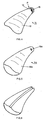
- Fig. 1
- ein vereinfachtes Schema einer nach dem erfindungsgemässen Verfahren arbeitenden Fertigungsanlage für die Optimierung industrieller Fertigung von Otoplastiken;
- Fig. 2
- in einer Darstellung analog zu derjenigen von Fig. 1, eine weitere Anlagenkonzeption;
- Fig. 3
- in Darstellung analog zu denjenigen der Figuren 1 und 2, eine noch weitere Anlagenkonzeption;
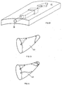
- Fig. 4
- schematisch ein Im-Ohr-Hörgerät mit auf bekannte Art und Weise aufgesetzter Cerumen-Schutzkappe;
- Fig. 5
- in Darstellung analog zu Fig. 4, ein nach dem erfindungsgemässen Verfahren mit Cerumen-Schutzkappe gefertigtes Im-Ohr-Hörgerät;
- Fig. 6
- ein Im-Ohr-Hörgerät mit einer auf bekannte Art und Weise eingearbeiteten Belüftungsnut;
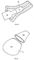
- Fig. 7(a) bis (f)
- anhand perspektivisch dargestellter Ausschnitte von Otoplastik-Schalenoberflächen, mit dem erfindungsgemässen Verfahren realisierte Belüftungsnuten;
- Fig. 8
- anhand eines schematischen Ausschnittes einer Otoplastik-Oberfläche, eine nach dem erfindungsgemässen Verfahren realisierte Belüftungsnut mit entlang ihrer Längsausdehnung variierendem Querschnitt bzw. variierender Querschnittsform;
- Fig. 9
- schematisch eine Im-Ohr-Otoplastik mit nach dem erfindungsgemässen Verfahren gearbeiteter, verlängerter Belüftungsnut;
- Fig. 10
- in Darstellung analog zu Fig. 9, eine Im-Ohr-Otoplastik mit mehreren erfindungsgemäss gefertigten Belüftungsnuten;
- Fig. 11(a) bis (e)
- Ausschnitte von Otoplastikschalen mit nach dem erfindungsgemässen Verfahren eingearbeiteten Belüftungskanälen verschiedener Querschnittsformen und Dimensionen;
- Fig. 12
- in einer Darstellung analog zu derjenigen von Fig. 8, ein nach dem erfindungsgemässen Verfahren realisierter Belüftungskanal in einer Otoplastikschale mit entlang seiner Längsausdehnung variierender Querschnittsform bzw. variierender Querschnittsfläche;
- Fig. 13
- in Analogie zur Darstellung von Fig. 9, schematisch eine Im-Ohr-Otoplastik mit nach dem erfindungsgemässen Verfahren eingearbeitetem, verlängerten Belüftungskanal;
- Fig. 14
- in Darstellung analog zu Fig. 10, eine Im-Ohr-Otoplastik mit mehreren Belüftungskanälen, gefertigt nach dem erfindungsgemässen verfahren;
- Fig. 15
- schematisch eine Länggsschnittdarstellung einer Im-Ohr-Otoplastik mit gerippter Innenfläche;
- Fig. 16
- einen Ausschnitt der Otoplastik gemäss Fig. 15 im Querschnitt, wobei die Rippen unterschiedliche Querschnittsflächen aufweisen;
- Fig. 17
- perspektivisch den Ausschnitt einer Otoplastikschale mit Innenrippung nach Fig. 15 oder 16, wobei die Rippen entlang ihrer Längsausdehnung unterschiedliche Querschnittsformen und Dimensionen aufweisen;
- Fig. 18
- in Darstellung analog zu Fig. 15, eine Im-Ohr-Otoplastik mit erfindungsgemäss gefertigter Aussenrippung;
- Fig. 19
- schematisch einen Ausschnitt aus einer gemäss Fig. 18 gerippten Otoplastikschale mit Rippen unterschiedlicher Querschnittsflächen;
- Fig. 20
- schematisch einen Querschnitt durch eine Otoplastik mit Aussenrippung, ggf. Innenrippung, und mindestens teilweise Füllmaterial-gefülltem Innenraum;
- Fig. 21
- schematisch einen Längsschnitt-Ausschnitt einer erfindungsgemäss gefertigten Otoplastikschale mit biege- und stauchflexibler Partie;
- Fig. 22
- schematisch im Längsschnitt, eine erfindungsgemäss gefertigte Im-Ohr-Otoplastik mit Aufnahmeraum für ein Elektronikmodul;
- Fig. 23
- die Otoplastik nach Fig. 22 bei ihrem Aufstülpen über ein Elektronikmodul;
- Fig. 24
- perspektivisch und schematisch, eine Im-Ohr-Otoplastik, wie insbesondere ein Im-Ohr-Hörgerät, mit zweiteiliger, separierbarer und assemblierbarer erfindungsgemäss gefertigter Otoplastikschale;
- Fig. 25
- ausschnittsweise und schematisch, die Integration von akustischen Leitern und Anpassgliedern zu einem akustisch/elektrischen oder elektrisch/akustischen Wandler, in einer erfindungsgemäss gefertigten Otoplastik;
- Fig. 26
- in Darstellung analog zu derjenigen von Fig. 25, die Anordnung zweier oder mehrerer akustischer Leiter in der Schale einer erfindungsgemäss gefertigten Otoplastikschale, und
- Fig. 27
- anhand eines vereinfachten Signalfluss/Funktionsblockdiagrammes, ein neuartiges Vorgehen bzw. eine neuartige Anordnung zu dessen Ausführung, bei dem bzw. der die Dynamik des Applikationsbereiches einer Otoplastik für deren Formgebung berücksichtigt wird.
- Fig. 1
- a simplified diagram of a manufacturing plant operating according to the inventive method for the optimization of industrial manufacturing of earmolds;
- Fig. 2
- in a representation analogous to that of FIG. 1, a further system concept;
- Fig. 3
- in representation analogous to those of Figures 1 and 2, yet another system design;
- Fig. 4
- schematically an in-the-ear hearing aid with a cerumen protective cap fitted in a known manner;
- Fig. 5
- in the illustration analogous to FIG. 4, an in-the-ear hearing device manufactured according to the method according to the invention with a cerumen protective cap;
- Fig. 6
- an in-the-ear hearing aid with a ventilation groove incorporated in a known manner;
- 7 (a) to (f)
- with the aid of perspectively illustrated sections of otoplastic shell surfaces, ventilation grooves realized with the method according to the invention;
- Fig. 8
- on the basis of a schematic section of an otoplastic surface, an aeration groove realized according to the method according to the invention with a cross-section or cross-sectional shape varying along its longitudinal extent;
- Fig. 9
- schematically an in-ear otoplastic with an elongated ventilation groove worked according to the method according to the invention;
- Fig. 10
- in illustration analogous to FIG. 9, an in-the-ear otoplastic with several ventilation grooves made according to the invention;
- 11 (a) to (e)
- Cutouts of otoplastic shells with ventilation channels of various cross-sectional shapes and dimensions incorporated according to the inventive method;
- Fig. 12
- in a representation analogous to that of FIG. 8, a ventilation duct realized according to the method according to the invention in an otoplastic shell with a cross-sectional shape or cross-sectional area that varies along its longitudinal extent;
- Fig. 13
- in analogy to the representation of FIG. 9, schematically an in-the-ear earmold with an elongated ventilation channel incorporated by the method according to the invention;
- Fig. 14
- in the illustration analogous to FIG. 10, an in-the-ear earmold with a plurality of ventilation channels, manufactured according to the method according to the invention;
- Fig. 15
- schematically shows a longitudinal section of an in-ear earmold with a ribbed inner surface;
- Fig. 16
- a cross section of the otoplastic according to FIG. 15, the ribs having different cross-sectional areas;
- Fig. 17
- perspective the section of an otoplastic shell with internal rib according to FIG. 15 or 16, the ribs having different cross-sectional shapes and dimensions along their longitudinal extent;
- Fig. 18
- in the illustration analogous to FIG. 15, an in-ear earmold with an outer rib according to the invention;
- Fig. 19
- schematically a section of an otoplastic shell with ribs according to FIG. 18 with ribs of different cross-sectional areas;
- Fig. 20
- schematically shows a cross section through an otoplastic with external ribbing, optionally internal ribbing, and at least partially filler-filled interior;
- Fig. 21
- schematically shows a longitudinal section of an otoplastic shell made according to the invention with a flexible and compressible portion;
- Fig. 22
- schematically in longitudinal section, an in-ear otoplastic manufactured according to the invention with a receiving space for an electronics module;
- Fig. 23
- 22 when it is put on via an electronic module;
- Fig. 24
- Perspectively and schematically, an in-ear otoplastic, such as in particular an in-the-ear hearing aid, with a two-part, separable and assemblable otoplastic shell manufactured according to the invention;
- Fig. 25
- in detail and schematically, the integration of acoustic conductors and matching elements into an acoustic / electrical or electrical / acoustic transducer, in an otoplastic manufactured according to the invention;
- Fig. 26
- 25, the arrangement of two or more acoustic conductors in the shell of an otoplastic shell produced according to the invention, and
- Fig. 27
- based on a simplified signal flow / functional block diagram, a new procedure or a new arrangement for its execution, in which the dynamics of the application area of an earmold is taken into account for its shaping.
Die im Anschluss an das Fertigungsverfahren beschriebenen Ausführungsformen von Otoplastiken werden vorzugsweise alle mit diesem beschriebenen Fertigungsverfahren hergestellt.Those described after the manufacturing process Embodiments of earmolds are preferably all manufactured with this manufacturing process described.
Wir verstehen unter einer Otoplastik eine Einrichtung, die unmittelbar ausserhalb der Ohrmuschel und/oder an der Ohrmuschel und/oder im Gehörgang appliziert wird. Dazu gehören Aussenohr-Hörgeräte, Im-Ohr-Hörgeräte, Kopfhörer, Lärmschutz- und Wasserschutzeinsätze etc.We understand an otoplastic to be a device that immediately outside the pinna and / or on the Auricle and / or in the ear canal is applied. To include outer ear hearing aids, in-ear hearing aids, headphones, Noise and water protection missions etc.
Das Fertigungsverfahren, welches bevorzugterweise eingesetzt wird, die nachfolgend im einzelnen beschriebenen Otoplastiken zu fertigen, beruht darauf, die Form eines individuellen Applikationsbereiches für eine beabsichtigte Otoplastik dreidimensional zu digitalisieren, dann die Otoplastik oder deren Schale durch ein additives Aufbauverfahren zu erstellen. Additive Aufbauverfahren sind auch unter dem Begriff "Rapid Prototyping" bekannt. Bezüglich derartiger im schnellen Prototypenbau bereits eingesetzter additiver Verfahren wird z.B. verwiesen auf:
- http://ltk.hut.fi/·koukka/RP/rptree.html (1)
oder auf - Wohlers Report 2000, Rapid Prototyping & Tooling State of the industry (2)
- http://ltk.hut.fi/·koukka/RP/rptree.html (1)
or on - Wohlers Report 2000, Rapid Prototyping & Tooling State of the industry (2)
Aus der Gruppe dieser für den schnellen Prototypenbau heute bekannten additiven Verfahren ergibt sich, dass Lasersintern, Laser- bzw. Stereolithographie oder das Thermojetverfahren sich besonders gut eignen, Otoplastiken bzw. deren Schalen aufzubauen und dabei insbesondere die nachfolgend beschriebenen speziellen Ausführungsformen. Deshalb sei, nur kurz zusammenfassend, auf Spezifikationen dieser bevorzugt eingesetzten additiven Aufbauverfahren eingegangen:
- Lasersintern: Auf einem Pulverbett wird, beispielsweise mittels eines Rollers, Heissschmelzpulver in einer dünnen Schicht aufgetragen. Mittels eines Laserstrahls wird die Pulverschicht verfestigt, wobei der Laserstrahl u.a. entsprechend einer Schnittschicht der Otoplastik bzw. Otoplastikschale mittels der 3D-Forminformation des individuellen Applikationsbereiches angesteuert wird. Es entsteht in dem im übrigen losen Pulver eine verfestigte Schnittschicht der Otoplastik bzw. deren Schale. Diese wird aus der Pulververlegeebene abgesenkt und darüber eine neue Pulverschicht aufgebracht, diese wiederum einer Schnittschicht entsprechend laserverfestigt, etc.
- Laser- bzw. Stereolithographie: Eine erste Schnittschicht einer Otoplastik bzw. einer Otoplastikschale wird mittels UV-Laser an der Oberfläche flüssigen Fotopolymers verfestigt. Die verfestigte Schicht wird abgesenkt und wird wieder von Flüssigpolymer bedeckt. Mittels des erwähnten UV-Lasers wird, auf der bereits verfestigten Schicht, die zweite Schnittschicht der Otoplastik bzw. deren Schale verfestigt. Wiederum erfolgt die Laserpositionssteuerung u.a. mittels der 3D-Daten bzw. Information des individuellen, vorgängig erfassten Applikationsbereiches.
- Thermojetverfahren: Die Konturbildung entsprechend einer Schnittschicht der Otoplastik bzw. der Otoplastikschale wird ähnlich wie bei einem Tintenstrahldrucker durch Flüssigauftrag u.a. gemäss der digitalisierten 3D-Forminformation, insbesondere auch des individuellen Applikationsbereiches vorgenommen. Danach wird die abgelegte Schnitt-"Zeichnung" verfestigt. Wiederum wird gemäss dem Prinzip der additiven Aufbauverfahren Schicht um Schicht zum Aufbau der otoplastik bzw. deren Schale abgelegt.
- Laser sintering: Hot melt powder is applied to a powder bed, for example using a roller, in a thin layer. The powder layer is solidified by means of a laser beam, the laser beam being driven, inter alia, according to a cut layer of the otoplastic or otoplastic shell by means of the 3D shape information of the individual application area. In the powder, which is otherwise loose, a solidified cut layer of the otoplastic or its shell is formed. This is lowered from the powder laying level and a new powder layer is applied over it, which in turn is laser-hardened according to a cut layer, etc.
- Laser or stereolithography: A first cut layer of an otoplastic or an otoplastic shell is solidified on the surface of liquid photopolymer by means of a UV laser. The solidified layer is lowered and is again covered by liquid polymer. Using the UV laser mentioned, the second cut layer of the otoplastic or its shell is solidified on the already solidified layer. Again, the laser position control takes place, among other things, by means of the 3D data or information of the individual, previously recorded application area.
- Thermojet process: The contour formation corresponding to a cut layer of the otoplastic or the otoplastic shell is carried out similarly to an ink jet printer by liquid application, inter alia, according to the digitized 3D shape information, in particular also the individual application area. Then the stored section "drawing" is solidified. Again, layer by layer to build up the otoplastic or its shell is deposited according to the principle of the additive build-up method.
Es kann bezüglich additiver Aufbauverfahren und der obgenannten bevorzugten auf folgende weitere Veröffentlichungen hingewiesen werden:
- http://www.padtinc.com/srv_rpm_sls.html (3)
- "Selective Laser Sintering (SLS) of Ceramics", Muskesh Agarwala et al., presented at the Solid Freeform Fabrication Symposium, Austin, TX, August 1999, (4)
- http://www.caip.rutgers.edu/RP_Library/process.html (5)
- http://www.biba.uni-bremen.de/groups/rp/lom.html bzw.
- http://www.biba.uni-bremen.de/groups/rp/rp_intro.html (6)
- Donald Klosterman et al., "Direct Fabrication of Polymer Composite Structures with Curved LOM", Solid Freeform Fabrication Symposium, University of Texas at Austin, August 1999, (7)
- http://lff.me.utexas.edu/sls.html (8)
- http://www.padtinc.com/srv_rpm_sla.html (9)
- http://www.cs.hut.fi/~ado/rp/rp.html (10)
- http://www.padtinc.com/srv_rpm_sls.html (3)
- "Selective Laser Sintering (SLS) of Ceramics", Muskesh Agarwala et al., Presented at the Solid Freeform Fabrication Symposium, Austin, TX, August 1999, (4)
- http://www.caip.rutgers.edu/RP_Library/process.html (5)
- http://www.biba.uni-bremen.de/groups/rp/lom.html or
- http://www.biba.uni-bremen.de/groups/rp/rp_intro.html (6)
- Donald Klosterman et al., "Direct Fabrication of Polymer Composite Structures with Curved LOM", Solid Freeform Fabrication Symposium, University of Texas at Austin, August 1999, (7)
- http://lff.me.utexas.edu/sls.html (8)
- http://www.padtinc.com/srv_rpm_sla.html (9)
- http://www.cs.hut.fi/~ado/rp/rp.html (10)
Grundsätzlich wird somit bei additiven Aufbauverfahren jeweils eine dünne Materialschicht auf einer Fläche abgelegt, sei dies wie beim Lasersintern oder der Stereolithographie noch ganzflächig, sei dies wie beim Thermojetverfahren bereits in der Kontur eines Schnittes der im Aufbau begriffenen Otoplastik bzw. deren Schale. Daraufhin wird die erwünschte Schnittform stabilisiert bzw. verfestigt.Basically, this is the case with additive construction methods each a thin layer of material on one surface filed, be it like laser sintering or the Stereolithography over the entire surface, be it like with Thermojet process already in the contour of a cut the earmold under construction or its shell. The desired cut shape is then stabilized or solidified.
Ist eine Schicht verfestigt, so wird darüber eine neue Schicht wie beschrieben abgelegt und diese wiederum verfestigt und mit der darunter liegenden, schon fertig gestellten Schicht verbunden. So wird Schicht um Schicht die Otoplastik bzw. deren Schale erstellt, durch additives Schicht-um-Schicht-Auftragen.Once a layer has solidified, a new one is placed over it Layer deposited as described and this in turn solidified and finished with the one underneath connected layer. So layer after layer the otoplastic or its shell is created by additives Layer-by-layer application.
Für die industrielle Fertigung wird bevorzugterweise jeweils nicht nur die Schnittschicht für eine individuelle Otoplastik bzw. deren Schale abgelegt bzw. verfestigt, sondern gleichzeitig mehrere je individuelle. Bei Lasersintern verfestigt z.B. der eine Laser, üblicherweise spiegelgesteuert, hintereinander die Schnittschichten mehrerer Otoplastiken bzw. deren Schalen, bevor alle verfestigten Schnittschichten gemeinsam abgesenkt werden. Daraufhin, nach Ablegen einer neuen Pulverschicht über alle bereits verfestigten und abgesenkten Schnittschichten, erfolgt wiederum-die Bildung der mehreren weiteren Schnittschichten. Trotz dieser parallelen Fertigung werden die jeweiligen Otoplastiken bzw. deren Schalen, digital gesteuert, individuell gefertigt.For industrial manufacturing is preferred not just the cut layer for an individual Otoplastic or its shell deposited or solidified, but several at the same time. at Laser sintering solidifies e.g. the one laser, usually mirror-controlled, the cut layers one behind the other several earmolds or their shells before all solidified cut layers are lowered together. Then, after dropping a new layer of powder over all already solidified and lowered cut layers, in turn - the formation of several more takes place Sectional layers. Despite this parallel manufacturing the respective earmolds or their shells, digital controlled, individually manufactured.
Dabei wird zur Verfestigung der mehreren Schnittschichten entweder ein einziger Laserstrahl eingesetzt und/oder es werden mehr als ein Strahl parallel betrieben und angesteuert.This is used to solidify the several cut layers either a single laser beam is used and / or it more than one beam is operated in parallel and driven.
Eine Alternative zu diesem Vorgehen besteht darin, jeweils mit einem Laser eine Schnittschicht zu verfestigen, während gleichzeitig für die Bildung einer weiteren Otoplastik bzw. Otoplastikschale die Pulverschicht abgelegt wird. Danach wird der nämliche Laser die bereitete Pulverschicht entsprechend der Schnittschicht für die weitere Plastik verfestigen, während die davor verfestigte Schicht abgesenkt und dort eine neue Pulverschicht abgelegt wird. Der Laser arbeitet dann intermittierend zwischen zwei oder mehreren im Aufbau begriffenen Otoplastiken bzw. Otoplastikschalen, wobei die durch die Pulverablage bei der Bildung einer der Schalen entstehende Lasereinsatz-Totzeit für die Verfestigung einer Schnittschicht einer anderen im Aufbau begriffenen Otoplastik ausgenützt wird.An alternative to this procedure is each to solidify a cut layer while using a laser at the same time for the formation of another otoplastic or Otoplastikschale the powder layer is deposited. After that the same laser becomes the prepared powder layer according to the cut layer for the further plastic solidify while the layer solidified before it lowered and a new powder layer is deposited there. The laser then works intermittently between two or several earmolds under construction or Otoplastic shells, the through the powder deposit at the Formation of a laser insert dead time resulting from the shells for the solidification of a cut layer of another in the Structure otoplastic is exploited.
In Fig. 1 ist schematisch dargestellt, wie, in einer
Ausführungsvariante, mittels Lasersintern oder Laser- bzw.
Stereolithographie mehrere Otoplastiken bzw. deren Schalen
in einem Parallelprozess industriell gefertigt werden. Über
dem Materialbett 1 für Pulver oder Flüssigmedium ist der
Laser mit Steuereinheit 5 und Strahl. 3 montiert. In
Position 1 verfestigt er die Schicht S1 einer ersten
Otoplastik bzw. deren Schale, angesteuert mit dem ersten
individuellen Datensatz D1. Danach wird er an einer
Verschiebevorrichtung 7 in eine zweite Position verstellt,
wo er mit dem individuellen Datensatz D2 die Schicht S2
entsprechend einer weiteren Individualkontur erstellt.
Selbstverständlich können mehrere der Laser als Einheit
verschoben werden und jeweils mehr als eine individuelle
Otoplastikschicht gleichzeitig erstellt werden. Erst wenn
die vorgesehenen Laser 5 in allen vorgesehenen Positionen
die jeweiligen individuellen Schichten erstellt haben, wird
mit der generell bei 9 dargestellten Pulverzuführung im
Falle des Lasersintern eine neue Pulverschicht abgelegt,
während (nicht dargestellt) bei der Laser- bzw.
Stereolithographie die verfestigten Schichten S im
Flüssigbett abgesenkt werden.1 schematically shows how, in one embodiment variant, several otoplastics or their shells are manufactured industrially in a parallel process by means of laser sintering or laser or stereolithography. The laser with
Gemäss Fig. 2 werden gleichzeitig an einem oder mehreren
Flüssigkeits- bzw. Pulverbetten 1, mit mehreren
gleichzeitig individuell angesteuerten Lasern 5, Schichten
individueller Otoplastiken bzw. deren Schalen verfestigt.
Wiederum wird mit der Pulverausgabeeinheit 9 nach
Erledigung dieser Verfestigungsphase und nach Stillsetzen
der Laser eine neue Pulverschicht abgelegt, während im
Falle der Laser- bzw. Stereolitographie die eben
verfestigten Schichten bzw. bereits verfestigten Aufbauten
im Flüssigbett abgesenkt werden.2 are simultaneously on one or more
Liquid or powder beds 1, with several
at the same time individually controlled
Gemäss Fig. 3 verfestigt Laser 5 am einen Pulver- bzw.
Flüssigbett 1a die Schicht S1, um danach zum Bett 1b
überzuwechseln (gestrichelt), woran während der
Verfestigungsphase am Bett 1a die Pulverauftragsvorrichtung
9b über einer vorgängig verfestigten Schicht S1- Pulver
abträgt bzw., bei der Laser- oder Stereolithographie, die
Schicht S1- abgesenkt wird. Erst wenn der Laser 5 am Bett
1b aktiv wird, erfolgt mit der Pulverausgabevorrichtung 9a
das Ablegen einer neuerlichen Pulverschicht über der eben
verfestigten Schicht S1 am Bett 1a bzw. erfolgt Absenken
der Schicht S1 im Flüssigbett 1a.According to FIG. 3,
Beim Einsatz der Thermojetverfahren und zur analogen Produktivitätserhöhung werden gleichzeitig Schnittschichten von mehr als einer Otoplastik bzw. deren Schalen abgelegt, praktisch in einem Zeichnungszug durch einen Auftragungskopf oder, parallel, durch mehrere.When using the Thermojet process and for analog Productivity increases become cut layers at the same time stored by more than one earmold or its shells, practically in one drawing by one Application header or, in parallel, by several.
Durch das dargestellte Verfahren ist es möglich, höchst komplexe Formen an Otoplastiken bzw. deren Schalen zu realisieren, und zwar sowohl was ihre Aussenformung mit individueller Anpassung an den Applikationsbereich anbelangt als auch was, bei einer Schale, deren Innenformung anbelangt. Überhänge, Ein- und Aussprünge können ohne weiteres realisiert werden. With the method shown, it is possible to achieve the highest complex shapes on earmolds or their shells realize both what their external shaping with individual adaptation to the application area as well as what, with a bowl whose Concerning internal shaping. Overhangs, jumps and jumps can be easily implemented.
Im weiteren sind Materialien für additive Aufbauverfahren bekannt, welche zu einer gummielastischen und doch formstabilen Schale geformt werden können, die, falls erwünscht, lokal unterschiedlich bis zu äusserst dünnwandig und trotzdem reissstabil realisiert werden kann.Furthermore there are materials for additive build-up processes known, which to a rubber-elastic and yet dimensionally stable shell can be molded, which, if desirable, locally different to extremely thin-walled and can still be realized tear-resistant.
In einer heute bevorzugten Ausführungsform wird die Digitalisierung des individuellen Applikationsbereiches, insbesondere des Applikationsbereiches für ein Hörgerät, dabei insbesondere Im-Ohr-Höhrgerät, bei einer spezialisierten Institution, im letzterwähnten Falle beim Audiologen, vorgenommen. Die dort aufgenommene Individualform, als digitale 3D-Information, wird, insbesondere im Zusammenhang mit Hörgeräten, an ein Produktionszentrum übermitteln, sei dies durch Übersendung eines Datenträgers, sei dies durch Internetverbindung etc. Im Produktionszentrum wird, insbesondere unter Einsatz der oben erwähnten Verfahren, die Otoplastik bzw. deren Schale, im betrachteten Fall also die Im-Ohr-Hörgeräteschale, individuell geformt. Bevorzugterweise wird auch dort die Fertigassemblierung des Hörgerätes mit den funktionellen Baugruppen vorgenommen.In a preferred embodiment today, the Digitization of the individual application area, in particular the application area for a hearing aid, in particular in-the-ear hearing aids specialized institution, in the latter case at Audiologist. The one recorded there Individual form, as digital 3D information, especially in connection with hearing aids Submit production center, be it by sending of a data carrier, be it through an internet connection etc. In the production center, especially using the above-mentioned methods, the otoplastic or its shell, in the case under consideration, the in-the-ear hearing aid shell, individually shaped. It is also preferred that there Complete assembly of the hearing aid with the functional Assemblies made.
Aufgrund der Tatsache, dass, wie erwähnt, die eingesetzten Thermoplastmaterialien im allgemeinen zu einer relativ elastischen, sich anschmiegenden Aussenform führen, ist auch die Formgebung bezüglich Druckstellen bei Otoplastiken bzw. deren Schalen weit weniger kritisch, als dies bis anhin der Fall war, was insbesondere für Im-Ohr-Otoplastiken von ausschlaggebender Bedeutung ist. So können Im-Ohr-Otoplastiken beispielsweise als Gehörschutzeinrichtungen, Kopfhörer, Wasserschutzeinrichtungen, aber insbesondere auch für Im-Ohr-Hörgeräte, ähnlich gummielastischen Pfropfen eingesetzt werden, und es schmiegt sich deren Oberfläche optimal an den Applikationsbereich, den Gehörgang, an. Ohne weiteres ist dabei das Einarbeiten eines oder mehrerer Belüftungskanäle in die Im-Ohr-Otoplastik möglich, um beim resultierenden, möglicherweise relativ dichten Sitz der Otoplastik im Gehörgang eine unbeeinträchtigte Belüftung zum Trommelfell sicherzustellen. Dabei kann mit den individuellen 3D-Daten des Applikationsbereiches bei der Fertigung auch der Innenraum der Plastik optimiert und optimal genutzt werden, auch individuell bezüglich der ggf. aufzunehmenden individuellen Aggregat-Konstellation wie bei einem Hörgerät.Due to the fact that, as mentioned, the used Thermoplastic materials in general are relative elastic, conforming outer shape is also the shape with regard to pressure points in earmolds or their shells far less critical than this was previously the case, especially for in-ear earmolds is of crucial importance. So can For example, in-ear earmolds Hearing protection devices, headphones, water protection devices, but especially for in-the-ear hearing aids, similar rubber-elastic stoppers are used, and it their surface hugs the Application area, the ear canal. Without further ado incorporating one or more ventilation channels possible in the in-ear earmold in order to possibly relatively tight fit of the otoplastic in the Ear canal undisturbed ventilation to the eardrum sure. You can do this with the individual 3D data of the application area in the manufacture of the Interior of the plastic can be optimized and optimally used, also individually with regard to the possibly to be included individual aggregate constellation like one Hearing aid.
Insbesondere bei Otoplastiken in der Form von Hörgeräten kann durch die zentrale Fertigung ihrer Schalen eine zentrale Abspeicherung und Verwaltung von Individualdaten, sowohl bezüglich des individuellen Applikationsbereiches, wie auch der individuellen Funktionsteile und ihrer Einstellungen, vorgenommen werden. Muss, aus welchen Gründen auch immer, eine Schale ersetzt werden, so kann sie ohne weiteres durch Abruf der individuellen Datensätze neuerlich gefertigt werden, ohne dass eine mühselige Neuanpassung - wie bis anhing - notwendig wäre.Especially with earmolds in the form of hearing aids can make a through the central production of their shells central storage and management of individual data, both with regard to the individual application area, as well as the individual functional parts and their Settings. Must, from which Whatever the reason, a bowl can be replaced, so it can easily by calling up the individual data records can be manufactured again without being cumbersome Readjustment - as until now - would be necessary.
Aufgrund der Tatsache, dass die für die Fertigung von Otoplastiken beschriebenen Verfahren, allerdings lediglich für den Prototypenbau, bekannt sind und in der Literatur beschrieben sind, erübrigt sich an dieser Stelle eine Wiedergabe aller technischen Einzelheiten bezüglich dieser Verfahren. Due to the fact that for the manufacture of The process described for earmolds, however, only for prototype construction, are known and in the literature are not necessary at this point Reproduction of all technical details regarding this Method.
Jedenfalls ergeben sich überraschenderweise aus Übernahme dieser aus dem Prototypenbau vorbekannten Technologien für die industrielle, kommerziell vertretbare Fertigung von Otoplastiken ganz wesentliche Vorteile, und zwar aus Gründen, die, an sich, im Prototypenbau nicht massgebend sind, wie z. B. Elastizität der verwendbaren thermoplastischen Materialien, der Möglichkeit, höchst dünnwandig individuell zu bauen etc.In any case, surprisingly, result from takeover this technology from prototype construction for the industrial, commercially viable manufacture of Otoplastics very significant advantages, and from Reasons that, in themselves, are not decisive in prototype construction are, such as B. elasticity of usable thermoplastic materials, the possibility of the highest to build thin-walled individually etc.
Zusammenfassend wird es durch Einsatz der erwähnten additiven Aufbauverfahren für die Fertigung von Otoplastiken bzw. deren Schalen möglich, daran verschiedene funktionale Elemente zu integrieren, die konstruktiv bereits während der Planung der Otoplastik am Rechner vorbereitet werden und die mit dem Aufbau der Otoplastik bzw. deren Schale erzeugt werden. Typischerweise wurden derartige funktionale Elemente bisher erst nach der Fertigstellung der Otoplastik bzw. deren Schale in diese eingepasst bzw. an diese angefügt, was an materiellen Schnittstellen oder Materialinhomogenität an den Verbindungsstellen erkenntlich ist.In summary, it is used by using the mentioned additive assembly processes for the production of Otoplastics or their shells possible, different Integrate functional elements that are constructive already during the planning of the earmold on the computer be prepared and that with the construction of the otoplastic or their shell are generated. Typically such functional elements so far only after Completion of the otoplastic or its shell in it fitted or added to this, what material Interfaces or material inhomogeneity at the Connection points is recognizable.
Für die erwähnten Otoplastiken, insbesondere mit elektronischen Einbauten, wie für Hörgeräte, dabei insbesondere für Im-Ohr-Hörgeräte, sind solche Elemente, die mit der vorgeschlagenen Technik direkt in die Otoplastikschale eingebaut werden können, beispielsweise: Aufnahmen und Halterungen für Bauteile, Cerumen-Schutzsysteme, Belüftungskanäle bei Im-Ohr-Otoplastiken, Stützelemente, die bei Im-Ohr-Otoplastiken letztere im Gehörgang haltern, wie sogenannte Krallen (englisch channel locks). For the mentioned earmolds, especially with electronic installations, such as for hearing aids especially for in-the-ear hearing aids, are such elements those with the proposed technique directly into the Otoplastic shell can be installed, for example: Holders and holders for components, cerumen protection systems, Ventilation channels for in-ear earmolds, Support elements, the latter in in-ear earmolds Hold ear canal, like so-called claws (English channel locks).
In Fig. 4 ist beispielsweise und schematisiert eine Im-Ohr-Otoplastik
11 dargestellt, beispielsweise ein Im-Ohr-Hörgerät,
bei dem der akustische Ausgang 13 zum Trommelfell
mittels einer Cerumen-Schutzkappe 15 geschützt ist. Diese
Schutzkappe 15 wird bis anhin in der Herstellung als
separater Teil auf die Schale 16 der Otoplastik 11
aufgebracht und beispielsweise durch Verkleben oder
Verschweissen fixiert. Wie in Fig. 5 in gleicher
Darstellung gezeigt, wird durch Einsatz der erwähnten
additiven Aufbauverfahren die Cerumen-Schutzkappe 15a
direkt an die Schale 16a der sonst identischen Im-Ohr-Otoplastik
11a integriert. An den in Fig. 4 mit P
schematisch angedeuteten Verbindungsstellen, wo bei
herkömmlichen Verfahren zwangsweise eine Material-Inhomogenität
bzw. -Schnittstelle entsteht, liegt gemäss
Fig. 5 keine derartige Schnittstellen vor, das Material der
Schale 16a geht homogen in dasjenige der Cerumen-Schutzkappe
15a über.An example of an in-ear earmold is shown schematically in FIG. 4
11, for example an in-the-ear hearing aid,
where the
Dies nur als Beispiel, wie bekannte Cerumen-Schutzsysteme und andere funktionale Elemente durch Einsatz des erwähnten Fertigungsverfahrens integral eingebaut werden können.This is only an example, like well-known cerumen protection systems and other functional elements by using the mentioned Manufacturing process can be built integrally.
Es werden nachfolgend einige spezifische neuartige Otoplastiken vorgestellt:Below are some specific novel ones Otoplastics presented:
Es ist bekannt, bei Im-Ohr-Otoplastiken, insbesondere bei Im-Oh-Hörgeräten, eine Belüftungsrinne auf der Aussenseite vorzusehen, wie dies schematisch in Fig. 6 dargestellt ist. Solche Belüftungsrinnen, wie sie heute eingesetzt werden, sind unter verschiedenen Aspekten keinesfalls optimiert:
- Bezüglich akustischem Verhalten: Die heute bekannten Belüftungsrinnen sind kaum an die jeweiligen akustischen Erfordernisse angepasst. So können sie kaum, bei aktiven Otoplastiken, wie z.B. bei Im-Ohr-Hörgeräten, dazu beitragen, die Rückkopplungsproblematik von elektromechanischem Ausgangswandler zu akustisch/elektrischem Eingangswandler wirksam lösen zu helfen. Auch bei passiven Im-Ohr-Otoplastiken, wie Gehörschutz-Einrichtungen, vermögen sie nicht, das erwünschte Schutzverhalten zu unterstützen und gleichzeitig die erwünschten Belüftungseigenschaften beizubehalten.
- Cerumenempfindlichkeit: Die heute eingesetzten Belüftungsrinnen in der Aussflächen von Im-Ohr-Otoplastiken sind äusserst Cerumenbildungs-empfindlich. Die Cerumenbildung vermag, je nach deren Intensität, rasch die vorgesehene Belüftungsrinnen bezüglich ihrer Belüftungseigenschaften zu beeinträchtigen, wenn nicht gar vollständig zu verstopfen.
- Regarding acoustic behavior: The ventilation channels known today are hardly adapted to the respective acoustic requirements. In active earmolds, such as in-the-ear hearing aids, they can hardly help to effectively solve the feedback problem from the electromechanical output transducer to the acoustic / electrical input transducer. Even with passive in-ear earmolds, such as hearing protection devices, they are unable to support the desired protective behavior and at the same time maintain the desired ventilation properties.
- Cerumen sensitivity: The ventilation channels used today in the outer surface of in-ear earmolds are extremely sensitive to cerumen formation. Depending on their intensity, the formation of cerumen can quickly, if not completely, block the ventilation channels provided with regard to their ventilation properties.
Es werden nachfolgend für Im-Ohr-Otoplastiken, dabei insbesondere für Im-Ohr-Hörgeräte oder Gehörschutzeinrichtungen, aber auch für Otoplastiken, die nur teilweise in den Gehörgang einragen, wie Kopfhörer, Belüftungsvorkehrungen vorgeschlagen, die die obgenannten Nachteile bekannter Vorkehrungen mindestens teilweise beheben.It will be used below for in-ear earmolds especially for in-the-ear hearing aids or Hearing protection devices, but also for otoplastics, the only partially protrude into the ear canal, like headphones, Ventilation arrangements suggested the above Disadvantages of known arrangements, at least in part remedy.
Hierzu werden nachfolgend Belüftungssysteme unterschieden, die
- nutenähnlich gegen die Gehörgangwandung mindestens zum Teil offen sind,
- gegen die Wandung des Gehörganges hin vollständig geschlossen sind.
- are at least partially open to the ear canal wall,
- are completely closed against the wall of the ear canal.
In den Fig. 7(a) bis (f) sind, anhand perspektivischer,
schematischer Darstellungen von Ausschnitten der am
Gehörgang anliegenden Aussenwandung 18 von im-Ohr-Otoplastiken,
neuartige Belüftungsnutprofile
ausschnittsweise dargestellt. Gemäss Fig. 7(a) ist das
Profil der Belüftungsnut 20a rechteck- oder quadratförmig
mit vorgegebenen, exakt eingehaltenen Dimensionierungsverhältnissen.
Gemäss Fig. 7(b) ist das Profil der
Belüftungsnut 20b Kreis- oder Ellipsen-sektorförmig,
wiederum mit exakt vorgegebener Querschnittsberandungskurve
21b. Durch exakte Vorgabe und Realisierung der
Querschnittsform der vorgesehenen Belüftungsnuten 20 kann
bereits eine gewisse Vorhersagbarkeit und Beeinflussung der
akustischen Öbertragungsverhältnisse entlang dieser Nut,
bei Anliegen an der Gehörgang-Innenwand, realisiert werden.
Selbstverständlich ist das akustische Verhalten auch
abhängig von der Länge, mit welcher sich die Nut 20 entlang
der Otoplastik-Aussenwand 18 erstreckt.7 (a) to (f) are, based on perspective,
schematic representations of sections of the
In den Fig. 7(c) bis (f) sind weitere Belüftungsnutprofile
dargestellt, welche zusätzlich Cerumen-geschützt sind. Das
Profil der Nut 20c gemäss Fig. 7(c) ist T-förmig.7 (c) to (f) are further ventilation groove profiles
shown, which are additionally protected by cerumen. The
Profile of the
Bezüglich der weiten Nutquerschnittsfläche bei 27c bewirken
die einkragenden Partien 23c und die sich daraus ergebende
Verengung 25c, gegen die Wand des Gehörganges hin, bereits
eine ansehnliche Cerumenschutzwirkung. Auch wenn Cerumen in
die Verengung 25c eindringt und dort verhärtet, ergibt sich
dadurch noch keine wesentliche Verengung oder gar
Verstopfung der Belüftungsnut, die nun zum geschlossenen
Belüftungskanal wird. In den Fig. 7(d) bis 7(f) ist, dem
erläuterten Prinzip von Fig. 7(c) folgend, die
Querschnittsform der weiten Nutpartie 27d bis 27f mit
unterschiedlicher Formung ausgebildet, gemäss Fig. 7(d)
kreissektorförmig bzw. entsprechend dem Sektor einer
Ellipse, gemäss Fig. 7(e) dreieckförmig, gemäss Fig. 7(f)
kreisförmig bzw. elliptisch.With regard to the wide groove cross-sectional area at 27c
the cantilevered
Durch gezielte Auslegung der Nutquerschnittsfläche, wie
dies nur beispielsweise anhand der Figuren 7 (a) bis 7 (f)
dargestellt ist, lässt sich sowohl bezüglich akustischen
Eigenschaften wie auch bezüglich Cerumenschutzwirkung eine
bereits in starkem Mass gegenüber herkömmlichen, mehr oder
weniger zufällig profilierten Belüftungsnuten verbesserte
Wirkung erzielen. Dabei werden die Profile unter
Berücksichtigung der erwähnten Cerumenschutzwirkung und der
akustischen Wirkung vorgängig rechnerisch modelliert und
exakt in die gefertigten Otoplastiken integriert. Hierzu
eignen sich in ganz besonderem Umfang die oben erläuterten
additiven Aufbauverfahren. Um nun weiter die akustische
Wirkung der Belüftungsnut zu optimieren, können entlang der
neuartigen Belüftungsnuten die unterschiedlichsten
akustischen Impedanzen realisiert werden, was
beispielsweise gemäss Fig. 8 in Entlüftungsnuten 29
resultiert, die, in ihrer Längsrichtung fortschreitend,
unterschiedliche Profile definieren, wie sie wahlweise in
Fig. 8 aus Profilen gemäss Fig. 7 zusammengestellt
dargestellt sind.Through targeted design of the groove cross-sectional area, such as
this only for example with reference to Figures 7 (a) to 7 (f)
is shown, can be both in terms of acoustic
Properties as well as regarding wax protection
already to a large extent compared to conventional, more or
less randomly profiled ventilation grooves
Make an impact. The profiles are under
Consideration of the wax protection effect mentioned and the
acoustic effect previously modeled and
exactly integrated into the manufactured earmolds. For this
the above-mentioned are particularly suitable
additive construction process. To continue the acoustic
The effect of the ventilation groove can be optimized along the
new types of ventilation grooves
acoustic impedances can be realized what
for example according to FIG. 8 in
Ähnlich der Auslegung passiver elektrischer Netzwerke, kann dadurch das akustische Übertragungsverhalten der am Gehörgang anliegenden Nut rechnerisch modelliert und überprüft werden, dann in die Im-Ohr-Otoplastik bzw. deren Schale integriert werden.Similar to the design of passive electrical networks, can thereby the acoustic transmission behavior of the am The auditory canal is modeled and checked, then in the in-ear earmold or their Shell are integrated.
Gezielt können vermehrt Cerumen-geschützte Abschnitte an diesbezüglichen, ausgesetzten Partien, wie in Fig. 8 bei A dargestellt, vorgesehen werden.Cerumen-protected sections can be targeted relevant, exposed parts, as in Fig. 8 at A shown, are provided.
Im weiteren kann es durchaus gewünscht sein, gerade mit
Blick auf die Optimierung der akustischen Verhältnisse, die
vorgesehenen Belüftungsnuten länger auszubilden, als dies
grundsätzlich durch die Längsausdehnung einer betrachteten
Im-Ohr-Otoplastik gegeben ist. Wie in Fig. 9 dargestellt,
wird dies dadurch erreicht, dass solche Nuten 31 mit
Ausbildung, wie sie anhand der Fig. 7 und 8 beispielsweise
dargestellt werden, in vorgegebenen Kurven entlang der
Oberfläche der Otoplastik geführt werden, beispielsweise
wie in Fig. 9 dargestellt, praktisch als die Otoplastik
gewindeartig umschlingende Nuten. Weitere
Optimierungsflexibilität wird dadurch erreicht, dass nicht
nur eine Belüftungsnut, sondern mehrere an der Oberfläche
der Otoplastik geführt werden, wie dies schematisch in Fig.
10 dargestellt ist. Die hohe Flexibilität der Nutauslegung
führt dazu, dass je nach Applikationsbereich im Gehörgang
gezielt unterschiedlich dimensionierte, bezüglich
Cerumenschutz sowie akustischen Übertragungsverhältnissen
jeweils optimierte Belüftungsnuten entlang der Otoplastik-Oberfläche
realisiert werden können. Furthermore, it may well be desired, especially with
Look at the optimization of the acoustic conditions that
provided ventilation grooves longer than this
basically by the longitudinal extent of a considered
In-ear earmold is given. As shown in Fig. 9,
this is achieved in that
Diese Ausbildungsvariante der neuartigen Belüftungssysteme beruht auf mindestens abschnittsweise völlig in die Otoplastik integrierten, gegen die Gehörgangwandung geschlossenen Belüftungskanälen. Dieses System wird anschliessend anhand seiner Ausbildung an einer Otoplastik-Schale erläutert. Es ist aber zu betonen, dass dann, wenn an der betrachteten Otoplastik keine weiteren Aggregate zu integrieren sind und sie als Vollplastik ausgebildet ist, die nachfolgenden Ausführungen sich selbstverständlich auch auf eine Kanalführung beliebig durch die erwähnte Vollplastik hindurch beziehen.This training variant of the new ventilation systems is based entirely on at least sections Integrated earmold, against the ear canal wall closed ventilation channels. This system will then based on his training on an earmold shell explained. However, it should be emphasized that if no further aggregates on the considered earmold are integrated and it is designed as a full plastic, the following explanations are of course also true on any channel guide through the mentioned Cover fully plastic.
In Fig. 11 sind in Analogie zu Fig. 7 unterschiedliche
Querschnittsformen und Flächenverhältnisse der
vorgeschlagenen Belüftungskanäle 33a bis 33e dargestellt.
Gemäss Fig. 11(a) hat der in die Otoplastikschale 35a
eingebaute Belüftungskanal 33a Rechteck- oder Quadrat-
Querschnittsform. Bei der Ausführungsform gemäss Fig. 11(b)
hat er, 35b, eine Kreissektor- oder Ellipsensektor-förmige
Kanalquerschnittsform. Bei der Ausführungsform gemäss Fig.
11(c) hat der vorgesehene Belüftungskanal 33c kreisförmige
oder elliptische Querschnittsform, während er bei der
Ausführungsvariante gemäss Fig. 11(d) eine dreieckförmige
Querschnittform aufweist.11 are different in analogy to FIG. 7
Cross-sectional shapes and area ratios of the
proposed
Bei der Ausführungsform gemäss Fig. 11 (e) weist die
Otoplastikschale eine komplexe Innenformung auf, z.B. eine
daran integrierte Halterungspartie 37. Für optimale
Platznutzung ist der hier vorgesehene Entlüftungskanal 35e
mit einer Querschnittsform angelegt, die auch komplexe
Formen der Otoplastikschale nutzt. Demnach erstreckt sich
seine Querschnittsform kompliziert teilweise in die an die
Schale 35e angebaute Halterungsleiste 37 hinein.In the embodiment according to FIG. 11 (e), the
Otoplastic shell has a complex internal shape, e.g. a
Rückblickend auf die Ausführungsvariante gemäss Abschnitt 2a) ist anzuführen, dass derartig komplexe, optimal den zur Verfügung stehenden Platz nutzende Querschnittsformen sich auch an gegen den Hörkanal offenen Belüftungsnuten realisieren lassen, ebenso, umgekehrt, Kanalführungen, wie sie für offene Nuten in den Fig. 9 und 10 dargestellt sind, an geschlossenen Belüftungskanälen.Looking back at the version according to section 2a) it must be stated that such complex, optimally the for Cross-sectional shapes using available space also on ventilation grooves open towards the auditory canal can be realized, as well, vice versa, channel guides, such as they are shown for open grooves in FIGS. 9 and 10, on closed ventilation ducts.
In Fig. 12 ist schliesslich eine Ausführungsvariante eines
voll integrierten Belüftungskanals 39 dargestellt, der
entlang seiner Längsausdehnung, wie dargestellt
beispielsweise in der Otoplastikschale 41, unterschiedliche
Querschnittsformen und/oder Querschnittsdimensionen
aufweist, womit im Sinne der Realisation unterschiedlicher
akustischer Impedanzelemente das akustische
Übertragungsverhalten optimiert werden kann. In diesem
Zusammenhang und auf den nachfolgenden Abschnitt 5)
verweisend, kann auch darauf hingewiesen werden, dass wegen
der Möglichkeit, komplexe akustische Impedanzverhältnisse
zu realisieren, Belüftungskanäle, insbesondere der in
diesem Abschnitt dargestellten geschlossenen Aufbauweise,
durchaus mindestens abschnittsweise gleichzeitig als
akustische Leiterabschnitte ausgangsseitig aktiver
elektromechanischer Wandler, wie ausgangsseitig von
Mikrophonen, beispielsweise bei Im-Ohr-Hörgeräten,
ausgenützt werden können.Finally, FIG. 12 shows an embodiment variant of a
fully integrated
In den Fig. 13 und 14 ist in Analogie zu den Fig. 9 und 10
dargestellt, wie einerseits an der jeweiligen Otoplastik 43
die in diesem Abschnitt erläuterten integrierten
Belüftungskanäle durch entsprechende Bahnführung verlängert
bzw. anderseits wie zwei und mehr der erwähnten Kanäle,
ggf. mit unterschiedlichen und/oder variierenden
Kanalquerschnitten, in Analogie zu Fig. 12, an der
Otoplastik integriert werden.13 and 14 is analogous to FIGS. 9 and 10
shown as on the one hand on the
Durch die in den Abschnitten 2a) und 2b) dargestellten, auch beliebig kombinierbaren Möglichkeiten eröffnen sich dem Fachmann eine Unzahl Auslegungsvarianten der neuartigen Belüftungssysteme und insbesondere ein grosses Ausmass an Freiheit, aufgrund der verschiedenen, für sich dimensionierbaren Parameter, für die jeweilige individuelle otoplastik optimalen Cerumenschutz und optimale akustische Übertragungsverhältnisse zu schaffen. Bei allen Ausführungsvarianten wird bevorzugterweise die spezifische individuelle Ausgestaltung des Systems berechnet bzw. rechnerisch modelliert, den erwähnten Bedürfnissen Rechnung tragend. Dann wird die individuelle Otoplastik realisiert. Wiederum eignet sich hierzu insbesondere das eingangs erläuterte Fertigungsverfahren mit additivem Aufbauprinzip, wie aus dem Prototypenbau bekannt, das dann mit dem optimierten Modellresultat gesteuert wird.By the shown in sections 2a) and 2b), Options that can be combined in any way also open up the expert a myriad of design variants of the new Ventilation systems and in particular a large extent Freedom, due to the different, for yourself dimensionable parameters, for the respective individual otoplastic optimal wax protection and optimal acoustic To create transfer relationships. At all Design variants are preferably the specific individual design of the system is calculated or modeled mathematically, the mentioned needs account supporting. Then the individual earmould is realized. Again, the above is particularly suitable for this explained manufacturing processes with additive construction principle, as known from prototype construction, which then with the optimized model result is controlled.
In diesem Abschnitt geht es darum, neuartige Otoplastiken vorzustellen, welche optimal der Dynamik der Applikationsbereiche angepasst sind. Es ist beispielsweise bekannt, dass herkömmliche Im-Ohr-Otoplastiken der relativ grossen Gehörgangdynamik, z.B. beim Kauen, nicht Rechnung zu tragen vermögen, aufgrund ihrer im wesentlichen über alles gleichen Formstabilität. Desgleichen vermögen beispielsweise die akustischen Leiter zwischen Aussenohr-Hörgeräten und Gehörgang einer Dynamik des Applikationsbereiches nicht frei zu folgen. Bei Im-Ohr-Otoplastiken tritt dieselbe Problematik, teilweise abgeschwächt, auch bei Gehörschutz-Einrichtungen, Kopfhörern, Wasserschutzeinsätzen etc. auf. Insbesondere wird dabei teilweise ihre intrinsische Funktion, beispielsweise Schutzwirkung, beeinträchtigt, wenn der erwähnten Applikationsbereichs-Dynamik zunehmend Rechnung getragen wird. Als Beispiel kann hierzu auf bekannte Gehörschutzeinrichtungen aus elastisch formveränderbaren Kunststoffen hingewiesen werden, die wohl der erwähnten Applikationsbereichs-Dynamik weitestgehend Rechnung tragen, dies aber auf Kosten ihres akustischen Übertragungsverhaltens.This section is about novel earmolds to imagine which optimally matches the dynamics of the Application areas are adapted. For example it is known to be conventional in-ear earmolds of relative great ear canal dynamics, e.g. when chewing, not bill are able to bear, due to their essentially over all the same dimensional stability. Can do the same for example the acoustic conductors between outer ear hearing aids and ear canal of a dynamic of the Application area not to follow freely. With in-ear earmolds the same problem occurs, partially weakened, even with hearing protection devices, Headphones, water protection inserts etc. In particular partly their intrinsic function, protective effect, for example, if the mentioned application area dynamics increasingly will be carried. As an example, this can be done on known Hearing protection devices made of resiliently deformable Plastics are pointed out, which is probably the one mentioned Largely take into account the dynamics of the application area, but at the expense of their acoustic Transmission behavior.
In Fig. 15 ist schematisch eine Längsschnittdarstellung
einer Im-Ohr-Otoplastik wiedergegeben, in Fig. 16 eine
schematische Querschnittsdarstellung eines. Abschnitts
dieser Otoplastik. Die Otoplastik - z.B. zur Aufnahme
elektronischer Komponenten - weist eine Schale 45 auf, die
strumpfartig, dünnwandig aus elastischem Material besteht.
Die Formstabilität der - beim dargestellten
Ausführungsbeispiel aussen glatten - Schalenhaut wird - wo
erwünscht - durch an der Schale integral innen aufgesetzte
Rippen 47 sichergestellt, die, bezüglich der Schalenhaut,
aus dem gleichen Material gefertigt sind.15 schematically shows a longitudinal section
reproduced an in-ear otoplastic, in Fig. 16 one
schematic cross-sectional representation of a. section
this earmold. The earmold - e.g. to record
electronic components - has a
Je nach erforderlicher Dynamik der Im-Ohr-Otoplastik
einerseits, um beispielsweise derjenigen des Gehörganges
Rechnung zu tragen und den Anforderungen bezüglich der
Abstützung und dem Schutz von Einbauten, wie bei einem Im-Ohr-Hörgerät,
wird der Verlauf der Wandstärke von
Schalenhaut 45, die Dichte und Gestalt der Rippen 47
vorgängig berechnet und danach die Otoplastik nach den
berechneten Daten aufgebaut. Wiederum eignet sich hierzu
das oben erläuterte Fertigungsverfahren unter Verwendung
additiver Aufbauverfahren ausserordentlich gut.
Selbstverständlich kann die eben erläuterte Ausbildung der
Im-Ohr-Otoplastik durchaus kombiniert werden mit einem
Belüftungssystem, wie es anhand der Figuren 7 bis 14
erläutert wurde. Insbesondere können die vorgesehenen
Rippen zur Beeinflussung der Formstabilität bzw.
Biegbarkeit in bestimmten Bereichen der Otoplastik auch mit
unterschiedlichem Querschnittsprofil ausgebildet werden,
ggf. auch in ihrer Längsausdehnung fortschreitend von einem
Querschnitt zum andern übergehend.Depending on the required dynamic of the in-ear earmold
on the one hand, for example that of the ear canal
To take into account and the requirements regarding the
Support and protection of internals, such as in an in-the-ear hearing aid,
the course of the wall thickness of
In Form einer perspektivischen Darstellung ist in Fig. 17
rein beispielsweise die Ausbildung der Aussenhaut 45 mit
Rippen 47 mit variierenden Querschnittsflächen entlang
ihrer Längsausdehnung schematisch dargestellt.17 is in the form of a perspective illustration
purely for example the formation of the
Anstelle oder ergänzend zu der gezielten Wandverstärkung
und gezielten Auslegung des Biege- bzw. Torsionsverhaltens,
kurz des Formverhaltens der Im-Ohr-Otoplastik, kann, wie
erwähnt, zusätzlich zur Innenrippenbemusterung, wie dies in
den Fig. 17 und 18 dargestellt ist, auch eine
Aussenrippenbemusterung vorgesehen werden. Gemäss den Fig.
18 und 19 wird hierzu, ggf. mit gebietsweise
unterschiedlicher Dichte, Ausrichtung und Profilform, auf
der Aussenfläche der Otoplastik 49 ein Muster von Rippen 51
aufgearbeitet.Instead of or in addition to the targeted wall reinforcement
and targeted interpretation of the bending or torsion behavior,
briefly the shape behavior of the in-ear earmold, how
mentioned, in addition to the inner rib pattern, as shown in
17 and 18, also a
Outer rib sampling can be provided. According to Fig.
18 and 19 will be used for this, possibly with areas
different density, orientation and profile shape
a pattern of
Gemäss Fig. 19 kann dies für die hier betrachteten
Otoplastiken mit Hohlraum eingesetzt werden, aber auch für
Otoplastiken mit keinem Hohlraum, also beispielsweise mit
keinen Elektronikkomponenten, z.B. für
Hörschutzeinrichtungen bzw. Wasserschutzeinrichtungen. Eine
solche Otoplastik ist in einer Querschnittsdarstellung
schematisch in Fig. 20 dargestellt. Dabei ist der Innenraum
53 beispielsweise aus äusserst kompressiblem
Absorptionsmaterial gefertigt und von einer formgebenden
Hautschale 55 umgeben mit der Rippenmusterung 57. Dabei
sind "Haut" 55 und die Rippenmusterung 57 gemeinsam
integral gefertigt. Hierzu eignet sich wiederum das
eingangs erläuterte Fertigungsverfahren unter Zuhilfenahme
additiver Aufbauverfahren. Wie weit in naher Zukunft diese
additiven Aufbauverfahren unter Wechsel der verarbeiteten
Materialen an einem Werkstück realisierbar sind, bleibe
dahingestellt. Sollte dies möglich werden, so ist die Bahn
frei, beispielsweise am Ausführungsbeispiel gemäss Fig. 20
auch den Füllstoff 53 gleichzeitig mit der Schalenhaut 55
und den Rippen 57 in jeweiligen Aufbauschichten sequentiell
aufzubauen.19, this can be done for those considered here
Otoplastics with cavity are used, but also for
Otoplastics with no cavity, for example with
no electronic components, e.g. For
Hearing protection devices or water protection devices. A
such otoplastic is in a cross-sectional view
shown schematically in Fig. 20. Here is the interior
53 for example from extremely compressible
Absorbent material manufactured and from a
Rückblickend insbesondere auf die Fig. 18 und 19 ist ersichtlich, dass mit Hilfe der Aussenrippenmuster gleichzeitig Belüftungskanäle bzw. -Freiräume gebildet werden können, wie dies rein schematisch und beispielsweise durch den Pfad P dargestellt ist.Looking back in particular at FIGS. 18 and 19 can be seen that with the help of the outer rib pattern at the same time ventilation channels or free spaces are formed can be, as this is purely schematic and for example is represented by the path P.
Nochmals auf Fig. 20 zurückkommend, ist es durchaus
möglich, falls erforderlich und wie in Fig. 20 gestrichelt
bei 57i dargestellt ist, auch dann, wenn die Im-Ohr-Otoplastik
materialgefüllt ist, also nicht zur Aufnahme
weiterer Baueinheiten, wie von Elektronikbaueinheiten,
bestimmt ist, an der Schalenhaut 55 ein Innenrippenmuster
57i vorzusehen. Wie weiter in Fig. 20 gestrichelt bei 59
dargestellt ist, können auch Otoplastiken geschaffen
werden, die wohl einen Hohlraum für aufzunehmende Aggregate
wie Elektronikkomponenten freilassen, bei denen aber der
Zwischenraum, zwischen einem solchen Hohlraum 59,
spezifisch auf die notwendigen Volumina und Formen der
zusätzlich einzubauenden Einheiten ausgelegt und die
Schalenhaut 55 beispielsweise durch ein federndes oder
schalldämmendes Material gefüllt ist oder einzubauende
Komponenten mit einem solchen Material bis zur Schalenhaut
55 ausgegossen sind.Returning to FIG. 20 again, it is entirely possible, if necessary and as shown in dashed lines in FIG. 20 at 57 i , even if the in-the-ear earmold is filled with material, that is to say not for accommodating further structural units, such as electronic structural units is determined to provide an
Die Schalenhaut 55 bzw. 45, gemäss den Figuren 15, 16 und
17, kann durchaus aus elektrisch leitendem Material
gefertigt sein, womit gleichzeitig eine elektrische
Abschirmwirkung für innenliegende Elektronikkomponenten
geschaffen wird. Dies gilt auch ggf. für die Füllung 53
gemäss Fig. 20.The
Anhand der Figuren 15 bis 20 wurde eine Otoplastik am Beispiel einer Im-Ohr-Otoplastik dargestellt, deren Schale mit innen- und/oder aussenliegenden Rippen formstabilisiert ist, was eine ausserordentlich leichte und gezielt formbare Bauweise ergibt. Selbstverständlich kann diese Bauweise falls erforderlich auch bei Aussenohr-Otoplastiken eingesetzt werden.On the basis of FIGS. 15 to 20, an otoplastic was used on Example of an in-ear earmold shown, its shell shape stabilized with internal and / or external ribs is what an extraordinarily light and specifically formable Construction results. Of course, this type of construction if necessary also with outer ear earmolds be used.
In Fig. 21 ist eine weitere Ausführungsvariante einer Im-Ohr-Otoplastik
dargestellt, welche gezielt in einem Bereich
biegbar bzw. stauchbar ist. Die Schale 61 einer Otoplastik,
wie insbesondere die Schale eines Im-Ohr-Hörgerätes, weist
hierzu in einem oder mehreren vorgegebenen Bereichen eine
Wellen- bzw. Faltenschlauchausbildung 63 auf, woran sie,
den jeweiligen Bedürfnissen entsprechend, bieg- bzw.
stauchbar ist. Auch wenn Fig. 21 dieses Vorgehen anhand der
Schale einer Im-Ohr-Otoplastik darstellt, lässt sich dieses
Vorgehen durchaus und falls erforderlich auch für eine
Aussenohr-Otoplastik realisieren. Wiederum wird hierzu
bevorzugterweise das eingangs erläuterte
Fertigungsverfahren eingesetzt.21 shows a further embodiment variant of an in-ear earmold
shown which are targeted in one area
is bendable or compressible. The
Auch bei diesem Ausführungsbeispiel kann, wie dies anhand von Fig. 20 erläutert wurde, das Innenvolumen der Otoplastik mit den Erfordernissen entsprechendem Füllmaterial gefüllt werden bzw. können darin integrierte Einbauten in solchem Füllmaterial eingebettet werden, woraus eine höhere Stabilität des Gerätes resultiert und verbesserte Akustikverhältnisse.In this embodiment too, as can be seen from this of Fig. 20, the inner volume of the Otoplasty with the corresponding requirements Filling material can be filled or integrated into it Internals are embedded in such filler material, which results in a higher stability of the device and improved acoustic conditions.
Insbesondere bei Im-Ohr-Hörgeräten besteht das Problem, dass der Applikationsbereich, d.h. der Gehörgang, seine Form ändert. Offensichtlich ist dies der Fall beim heranwachsenden Menschen. Aber auch bei Erwachsenen ändert sich der Gehörgang teilweise stark, meist in verengendem Sinne (z.B. sogenanntes Taucher-Ohr).The problem with in-the-ear hearing aids in particular that the application area, i.e. the ear canal, his Shape changes. Obviously, this is the case with adolescent people. But changes also in adults the ear canal becomes partially strong, usually narrowing Senses (e.g. so-called diver's ear).
Bei Im-Ohr-Hörgeräten ergibt sich damit herkömmlicherweise das Problem, dass auch dann, wenn die Hörgeräteeinbauten an sich über lange Lebensabschnitte beibehalten werden könnten, beispielsweise lediglich das Übertragungsverhalten des Hörgerätes den jeweiligen Hörverhältnissen entsprechend nachgestellt werden müsste, trotzdem immer wieder neue Hörgeräte konzipiert werden müssen, lediglich aufgrund der Tatsache, dass die vormaligen nicht mehr zufriedenstellend in den Gehörgang passen.This results conventionally in in-the-ear hearing aids the problem that even when the hearing aid internals on to be maintained over long periods of life could, for example, only the transmission behavior of the hearing aid according to the respective listening conditions would have to be readjusted, but always new ones Hearing aids need to be designed just because of the Fact that the previous one is no longer satisfactory fit into the ear canal.
Bereits die anhand von Abschnitt 3 erläuterten Massnahmen
ergeben die Möglichkeit, dies zu verbessern, aufgrund der
Tatsache, dass damit eine selbsttätige Formanpassung der
Otoplastik an jeweilig sich ändernde Applikationsbereiche
ermöglicht wird. In diesem Abschnitt sollen diesbezüglich
weitere Massnahmen, insbesondere anhand von Im-Ohr-Otoplastiken,
erläutert werden. Es ist aber darauf
hinzuweisen, dass auch bei Aussenohr-Otoplastiken, wie
Aussenohr-Hörgeräten, damit die Möglichkeit eröffnet wird,
das "Gehäuse" zu wechseln, und zwar nicht nur, wenn dies
vom Tragkomfort her notwendig wird, sondern auch, nach
Wunsch, beispielsweise um das ästhetische Erscheinungsbild
derartiger Aussenohr-Hörgeräte zu wechseln.Already the measures explained in
In Fig. 22 ist eine Im-Ohr-Otoplastik 65 schematisch und im
Längsschnitt gezeigt, woran die Ausformung des Inneraumes
67 im wesentlichen der Form des in Fig. 23 schematisch
dargestellten, aufzunehmenden Elektronikmoduls 69
entspricht. Die Otoplastik 65 besteht aus gummielastischem
Material und kann, wie in Fig. 23 gezeigt, über das
Elektronikmodul 69 gestülpt werden. Die Formung des
Innenraumes 67 ist dergestalt, dass der oder ggf. die
mehreren aufzunehmenden Module formschlüssig direkt durch
die Otoplastik 65 positioniert und gehaltert werden.
Aufgrund dieses Vorgehens ist es leicht möglich, ein und
dieselben Elektronikmodule 69 mit unterschiedlichen
Otoplastiken 65 zu versehen, um so beispielsweise bei einem
heranwachsenden Kind der sich verändernden
Gehörgangausbildung Rechnung zu tragen. Die Otoplastik wird
für das Im-Ohr-Hörgerät praktisch zum leicht
auswechselbaren Wegwerf-Accessoire. Nicht nur, um sich
ändernden Verhältnissen am Applikationsbereich, nämlich dem
Gehörgang, Rechnung zu tragen, sondern auch einfach aus
Verschmutzungsgründen, kann die Otoplastik 65 leicht
gewechselt werden. Dieses Konzept kann sogar dazu
ausgenützt werden, ggf. - beispielsweise bei
Gehörgangentzündungen - Medizinalapplikationen vorzunehmen,
beispielsweise durch Applikation von Medikamenten an die
Otoplastik-Aussenfläche oder mindestens, um in
regelmässigen Abständen sterilisierte Otoplastiken
einzusetzen.In Fig. 22 an in-
Das anhand der Figuren 22 und 23 dargestellte Konzept lässt
sich selbstverständlich mit den in den Abschnitten 2) und
3) dargelegten Konzepten kombinieren, und es wird
bevorzugterweise die Otoplastik 65 nach dem in Abschnitt 1)
erläuterten Fertigungsverfahren hergestellt, welches die
Ausbildung komplexester Innenformen zur spiel- und
vibrationsfreien Aufnahme des Moduls 69 ermöglicht.The concept illustrated with reference to FIGS. 22 and 23 leaves
of course with the in sections 2) and
3) combine outlined concepts and it will
preferably the otoplastic 65 according to the method described in section 1)
manufacturing process explained, which the
Training of the most complex interior shapes for play and
enables vibration-free inclusion of
Wie aus den Fig. 22 und 23 ersichtlich, wird beispielsweise
als Teil der Modulhalterung die sonst bei herkömmlichen Im-Ohr-Hörgeräten
vorgesehene Phaseplate 1 integral mit der
Otoplastik gebaut. Dasselbe gilt für weitere Halterungen
und Aufnahmen für Elektronikkomponenten des Hörgerätes.
Realisiert man das unter Abschnitt 1) dargelegte Schicht-um-Schicht-Aufbauverfahren,
wie in Fig. 22 strichpunktiert
und in der mit dem Pfeil AB angedeuten Richtung, so dürfte
es ohne weiteres möglich sein, die Otoplastik in der
erwähnten Aufbaurichtung AB je nach Erfordernissen in den
jeweiligen Bereichen aus unterschiedlichen Materialien zu
fertigen. Dies gilt auch für die in den Abschnitten 2) und
3) dargelegten Otoplastiken sowie für die in den folgenden
Abschnitten 5), 6) und 7) erläuterten. Am Beispiel von Fig.
22 ist es somit durchaus möglich, den Bereich 65a aus
gummielastischem Material zu fertigen, hingegen den
Ausgangsbereich 65b aus formstabilerem Material.As can be seen from FIGS. 22 and 23, for example as part of the module holder, the phase plate 1 otherwise provided in conventional in-the-ear hearing aids is built integrally with the otoplastic. The same applies to further holders and receptacles for electronic components of the hearing aid. If the layer-by-layer build-up method described in section 1) is implemented, as shown by dash-dotted lines in FIG. 22 and in the direction indicated by the arrow AB, then it should be possible without further ado, the earmold in the mentioned build-up direction AB depending on the requirements to be made in the respective areas from different materials. This also applies to the earmoulds described in sections 2) and 3) and to those explained in the following sections 5), 6) and 7). Using the example in FIG. 22, it is therefore entirely possible to manufacture the
In Fig. 24 ist eine weitere Ausführungsform einer
Otoplastik, wiederum als Beispiel anhand eines Im-Ohr-Hörgeräts,
dargestellt, welche ein einfaches, rasches
Auswechseln der inneren Einbauten ermöglicht. Grundsätzlich
wird dabei vorgeschlagen, an einer Im-Ohr-Otoplastik mit
Einbauten die Otoplastik-Schale mehrteilig und
assemblierbar auszubilden, wie dies Fig. 24 zeigt. Mittels
schnell betätigbaren Verschlüssen, wie Einrastverschlüssen,
Einklinkverschlüssen oder gar bajonettähnlichen
Verschlüssen, wird ermöglicht, an der Im-Ohr-Otoplastik
Gehäuseteile 73a und 73b rasch voneinander zu trennen, die
Einbauten wie Elektronikmodule daraus zu entfernen und sie
in eine neue Schale wieder einzubauen, ggf. mit geänderter
Aussenformung oder grundsätzlich in eine neue Schale, auch
wenn dies beispielsweise aus Reirügungsgründen,
Sterilitätsgründen etc. erforderlich ist. Wird dabei
vorgesehen, die bereits gebrauchte Schale wegzuwerfen, ist
es ohne weiteres möglich, die Verbindungen der Schalenteile
so auszubilden, dass die Schale nur zerstörend geöffnet
werden kann, beispielsweise indem von aussen nicht
zugängliche Verriegelungsorgane wie Klinken vorgesehen
werden und die Schale für deren Entfernung aufgeschnitten
wird. 24 is another embodiment of a
Otoplasty, again as an example using an in-the-ear hearing aid,
shown, which is a simple, quick
Replacing the internal fittings allows. in principle
it is proposed to use an in-ear earmold
Built-in multi-part and the earmold shell
to be designed to be assembled, as shown in FIG. 24. through
fast-acting closures, such as snap locks,
Latches or even bayonet-like
Closures are made possible on the in-ear earmold
Auch diese Ausführungsform kann selbstverständlich mit den bis anhin beschriebenen und noch zu beschreibenden Ausführungsvarianten kombiniert werden.This embodiment can of course with the described so far and still to be described Design variants can be combined.
Bei Aussenohr- wie auch bei Im-Ohr-Hörgeräten ist es üblich, vorgesehene akustisch/elektrische Wandler oder elektro-akustische Ausgangswandler eingangs- bzw. ausgangsseitig über als eigenständige Teile assemblierte akustische Leiter, nämlich röhrchenähnliche Gebilde, mit der Umgebung des Hörgerätes zu koppeln, oder aber, insbesondere bei eingangsseitigen akustisch/elektrischen Wandlern, diese mit ihrer Aufnahmefläche unamittelbar im Bereiche der Oberflächen des Hörgerätes zu platzieren, ggf. lediglich durch geringfügige Hohlräume und Schutzvorkehrungen von der Umgebung getrennt.It is with outer ear as well as in-ear hearing aids usual, provided acoustic / electrical transducers or electro-acoustic output converter input or on the output side via assembled as independent parts acoustic conductors, namely tube-like structures with to couple the surroundings of the hearing aid, or else, especially with acoustic / electrical input Transducers, these with their receiving area directly in the To place areas of the surfaces of the hearing aid, if necessary only by slight voids and Protective measures separated from the environment.
Dabei besteht bei der Konzeption derartiger Hörgeräte eine relativ grosse Bindung, wo im Hörgerät die eigentlichen Wandler und wo am Hörgerät die eigentlichen Kopplungsöffnungen zur Umgebung vorzusehen sind. Es wäre höchst wünschbar, bezüglich der Anordnung von Kopplungsöffnungen zur Umgebung und Anordnung der erwähnten Wandler innerhalb des Hörgerätes grösstmögliche Konzeptionsfreiheit zu haben.There is one in the design of such hearing aids relatively large bond, where the actual ones in the hearing aid Converter and where on the hearing aid the actual Coupling openings to the environment must be provided. It would be highly desirable regarding the arrangement of Coupling openings to the environment and arrangement of the mentioned Largest possible converter within the hearing aid To have freedom of concept.
Dies wird grundsätzlich dadurch erreicht, dass die erwähnten akustischen Leiter - eingangsseitig von akustisch/elektrischen Wandlern bzw. ausgangsseitig von elektrisch/akustischen Wandlern - in die Otoplastik bzw. in die Wandung von Otoplastikschalen integriert werden. This is basically achieved by the fact that mentioned acoustic conductor - input side of acoustic / electrical transducers or on the output side of electrical / acoustic transducers - in the earmold or in the wall of otoplastic shells can be integrated.
In Fig. 25 ist dies rein schematisch dargestellt. Ein
Wandlermodul 75 weist einen akustischen Ein- bzw. Ausgang
77 auf. Die Schale 79 der Otoplastik eines Im-Ohr- oder
eines Aussenohr-Hörgerätes oder eines Kopfhörers weist, in
ihr integriert, einen akustischen Leiter 81 auf. Er liegt
mindestens abschnittsweise und wie in Fig. 25 dargestellt
innerhalb der Wandung der Otoplastikschale 79. Mittels
akustischer Stichleitungen bzw. Leitungsabschnitten 83 wird
vorzugsweise die jeweilige akustische Impedanz des
akustischen Leiters 81 angepasst. Dieses Konzept, mit Blick
auf Aussenohr-Hörgeräte, ermöglicht es, entlang des
Hörgerätes versetzt und wo erwünscht akustische
Eingangsöffnungen 85 vorzusehen, diese über in der
Otoplastik bzw. deren Schale 87 integrierte akustische
Leiter 89 an die vorgesehenen akustisch/elektrischen
Wandler 91 anzukoppeln, im wesentlich unabhängig davon, wo
diese Wandler 91 im Hörgerät eingebaut werden. So ist in
Fig. 26 nur beispielsweise dargestellt, zwei Wandler zu
einem Modul zu zentralisieren und ihre Eingänge mit den
erwünschten Aufnahmeöffnungen 85 durch die erwähnte Führung
der akustischen Leiter 89 zu verbinden. Aus Betrachtung der
Figuren 25 und 26 und den Ausführungen in Abschnitt 2)
betreffs der neuartigen Belüftungssysteme wird ersichtlich,
dass es durchaus möglich wird, Belüftungskanäle auch als
akustische Leiterkanäle zu nutzen, insbesondere wenn dabei,
wie in Fig. 25 schematisiert, mittels akustischer
Anpassglieder 83 die akustischen Impedanzverhältnisse
gezielt ausgelegt werden.This is shown purely schematically in FIG. 25. On
Bei der Fertigung von Otoplastiken, insbesondere von Im-Ohr-Otoplastiken, wird jede individuell für deren jeweiligen Träger angepasst. Deshalb wäre es äusserst erwünscht, jede gefertigte Otoplastik, wie erwähnt insbesondere jede Im-Ohr-Otoplastik, dabei ganz besonders jedes Im-Ohr-Hörgerät, zu kennzeichnen. Es wird deshalb vorgeschlagen, in die Otoplastik hinein bzw. in deren Schale, durch Einkerbungen und/oder durch Auswölbungen eine individuelle Kennzeichnung vorzusehen, welche nebst dem individuellen Besteller - z.B. Hersteller - Produktserienummer, Links- Rechtsapplikation etc. enthalten. kann. Eine solche Kennzeichnung wird in weitaus bevorzugter Art und Weise bei der Fertigung der Otoplastik mit dem unter 1) beschriebenen Abtragverfahren erstellt. Damit wird sichergestellt, dass ab der Fertigung jegliche Verwechslung der Otoplastiken ausgeschlossen ist. Insbesondere wichtig ist dies bei der nachfolgenden, ggf. automatisierten Assemblierung mit weiteren Modulen, so beispielsweise der Assemblierung von Im-Ohr-Hörgeräten.In the manufacture of earmolds, especially in-ear earmolds, each one is individual for their adapted to each carrier. Therefore it would be extremely desirable, every manufactured earmold, as mentioned especially any in-the-ear earmould, especially so to mark each in-the-ear hearing aid. It will therefore proposed into or into the otoplastic Shell, by indentations and / or by bulges one to provide individual labeling, which in addition to the individual customer - e.g. Manufacturer - Product serial number, left-right application etc. included. can. Such labeling is much more preferred Way of manufacturing the earmold with the removal process described under 1). So that will ensures that any confusion from manufacturing the earmold is excluded. Particularly important this is the case with the following, possibly automated Assembly with other modules, such as the Assembly of in-the-ear hearing aids.
Dieses Vorgehen kann selbstverständlich kombiniert mit einem oder mehreren der unter den Abschnitten 2) bis 5) beschriebenen Aspekten realisiert werden.This can of course be combined with one or more of the sections 2) to 5) described aspects can be realized.
Für die Formnahme von Otoplastiken für die Im-Ohr-Applikation,
so beispielsweise für Im-Ohr-Hörgeräte, ist es
heute üblich, vom Gehörgang, beispielsweise in Silikon,
einen Abdruck zu nehmen. Berücksichtigt man nun die relativ
grosse Bewegungsdynamik des Gehörganges, beispielsweise
beim Kauvorgang, so ist ersichtlich, dass die Abstützung
der Im-Ohr-Otoplastikform auf einen praktisch einer
Momentaufnahme entsprechenden Abdruck kaum zu einem
Resultat führt, das im Gebrauch völlig zu befriedigen
vermag. Wie dies nun in Fig. 27 anhand eines vereinfachten
Funktionsblock/Signalflussdiagrammes dargestellt ist, wird
vom dynamischen Applikationsgebiet, dargestellt durch den
Block 93, an mehreren der in der Praxis erfolgenden Dynamik
entsprechenden Positionen Form genommen bzw., filmähnlich,
die Dynamik des Applikationsbereiches an sich registriert.
Die resultierenden Datensätze werden in einer
Speichereinheit 95 abgelegt. Auch bei herkömmlichem
Vorgehen durch Abdrucknahme kann dies durchaus realisiert
werden, indem vom Applikationsbereich in zwei oder mehr
Positionen die der praktischen Dynamik entsprechenden
Abdrücke genommen werden.For the shaping of earmolds for in-ear application,
for example for in-the-ear hearing aids, it is
common today, from the ear canal, for example in silicone,
to take an impression. If you take into account the relative
great movement dynamics of the ear canal, for example
when chewing, it can be seen that the support
the in-ear otoplastic mold to practically one
Snapshot corresponding impression hardly to one
Result leads to fully satisfy that in use
can. As now in Fig. 27 using a simplified
Function block / signal flow diagram is shown
of the dynamic application area, represented by the
Es werden anschliessend diese Abdrücke abgetastet und die
jeweiligen digitalen Datensätze in die Speichereinheit 95
abgelegt. Als weitere Möglichkeit kann beispielsweise die
Dynamik des Applikationsbereiches durch Röntgenaufnahmen
erfasst werden.These prints are then scanned and the
respective digital data records into the
Es werden mithin je nach zu erzielender Genauigkeit mehrere
"Bilder" oder gar praktisch ein "Film" des Bewegungsmusters
vom interessierenden Applikationsbereich registriert. Die
in der Speichereinheit 95 registrierten Daten werden
anschliessend einer Recheneinheit 97 zugeführt.
Ausgangsseitig steuert die Recheneinheit 97 den
Fertigungsprozess 99 für die Otoplastik. Werden z.B., und
wie bis heute üblich, Im-Ohr-Otoplastiken gefertigt mit
relativ harter Schale, so berechnet die Recheneinheit 97
aus den an der Speichereinheit 95 abgelegten Dynamikdaten
und ggf., wie bei K schematisch dargestellt, weiteren
Fertigungsparametern, die beste Passform für die
Otoplastik, damit optimaler Tragkomfortfort im Alltag
erzielt wird, bei Erhalt ihrer Funktionalität. Wird die zu
fertigende Otoplastik nach dem in Abschnitt 3) dargelegten
Prinzip realisiert, so wird an der Recheneinheit 97
ermittelt, welche Otoplastikbereiche wie zu gestalten sind
bezüglich ihrer Flexibilität, Biegbarkeit, Stauchbarkeit
etc. Ausgangsseitig steuert, wie erwähnt, die Recheneinheit
97 den Fertigungsprozess 99, bevorzugterweise dabei den
Fertigungsprozess, wie er im Abschnitt 1) als bevorzugter
Prozess dargelegt wurde.There are therefore several depending on the accuracy to be achieved
"Images" or practically a "film" of the movement pattern
registered by the application area of interest. The
data registered in the
Claims (20)
Priority Applications (1)
| Application Number | Priority Date | Filing Date | Title |
|---|---|---|---|
| EP04017958A EP1555851A3 (en) | 2000-06-30 | 2000-09-25 | Method for the production of otoplastics and corresponding otoplastic |
Applications Claiming Priority (3)
| Application Number | Priority Date | Filing Date | Title |
|---|---|---|---|
| WOPCT/CH00/00356 | 2000-06-30 | ||
| PCT/CH2000/000356 WO2002003756A1 (en) | 2000-06-30 | 2000-06-30 | Method for producing in-ear hearing aids and in-ear hearing aid |
| EP00960273A EP1295509B1 (en) | 2000-06-30 | 2000-09-25 | Method for the production of otoplastics and corresponding otoplastic |
Related Parent Applications (1)
| Application Number | Title | Priority Date | Filing Date |
|---|---|---|---|
| EP00960273A Division EP1295509B1 (en) | 2000-06-30 | 2000-09-25 | Method for the production of otoplastics and corresponding otoplastic |
Related Child Applications (1)
| Application Number | Title | Priority Date | Filing Date |
|---|---|---|---|
| EP04017958A Division EP1555851A3 (en) | 2000-06-30 | 2000-09-25 | Method for the production of otoplastics and corresponding otoplastic |
Publications (2)
| Publication Number | Publication Date |
|---|---|
| EP1427251A2 true EP1427251A2 (en) | 2004-06-09 |
| EP1427251A3 EP1427251A3 (en) | 2006-08-16 |
Family
ID=4358099
Family Applications (4)
| Application Number | Title | Priority Date | Filing Date |
|---|---|---|---|
| EP00938437A Expired - Lifetime EP1295508B1 (en) | 2000-06-30 | 2000-06-30 | Method for producing in-ear hearing aids and in-ear hearing aid |
| EP00960273A Expired - Lifetime EP1295509B1 (en) | 2000-06-30 | 2000-09-25 | Method for the production of otoplastics and corresponding otoplastic |
| EP04004629A Withdrawn EP1427251A3 (en) | 2000-06-30 | 2000-09-25 | Method for the production of otoplastics and corresponding otoplastic |
| EP04017958A Withdrawn EP1555851A3 (en) | 2000-06-30 | 2000-09-25 | Method for the production of otoplastics and corresponding otoplastic |
Family Applications Before (2)
| Application Number | Title | Priority Date | Filing Date |
|---|---|---|---|
| EP00938437A Expired - Lifetime EP1295508B1 (en) | 2000-06-30 | 2000-06-30 | Method for producing in-ear hearing aids and in-ear hearing aid |
| EP00960273A Expired - Lifetime EP1295509B1 (en) | 2000-06-30 | 2000-09-25 | Method for the production of otoplastics and corresponding otoplastic |
Family Applications After (1)
| Application Number | Title | Priority Date | Filing Date |
|---|---|---|---|
| EP04017958A Withdrawn EP1555851A3 (en) | 2000-06-30 | 2000-09-25 | Method for the production of otoplastics and corresponding otoplastic |
Country Status (8)
| Country | Link |
|---|---|
| EP (4) | EP1295508B1 (en) |
| JP (2) | JP2004502392A (en) |
| CN (1) | CN100477815C (en) |
| AU (4) | AU5384800A (en) |
| CA (2) | CA2412481C (en) |
| DE (2) | DE50010130D1 (en) |
| DK (1) | DK1295509T3 (en) |
| WO (2) | WO2002003756A1 (en) |
Cited By (2)
| Publication number | Priority date | Publication date | Assignee | Title |
|---|---|---|---|---|
| EP2615854A1 (en) | 2012-06-14 | 2013-07-17 | Oticon A/s | Housing for a hearing aid |
| EP3451704A1 (en) * | 2017-08-30 | 2019-03-06 | GN Hearing A/S | Earpiece with canal microphone, ambient microphone and receiver |
Families Citing this family (36)
| Publication number | Priority date | Publication date | Assignee | Title |
|---|---|---|---|---|
| US6540045B1 (en) | 2000-06-30 | 2003-04-01 | Phonak Ag | Method for manufacturing an ear device and ear device |
| AU5384800A (en) * | 2000-06-30 | 2002-01-14 | Phonak Ag | Method for producing in-ear hearing aids and in-ear hearing aid |
| US7014010B2 (en) * | 2000-06-30 | 2006-03-21 | Phonak Ag | Method for manufacturing an ear device and ear device |
| US7625335B2 (en) | 2000-08-25 | 2009-12-01 | 3Shape Aps | Method and apparatus for three-dimensional optical scanning of interior surfaces |
| CA2421294A1 (en) * | 2000-09-25 | 2002-03-28 | Phonak Ag | Intra-auricular otoplastic |
| US7050876B1 (en) | 2000-10-06 | 2006-05-23 | Phonak Ltd. | Manufacturing methods and systems for rapid production of hearing-aid shells |
| DK1368986T3 (en) | 2001-03-02 | 2012-02-27 | 3Shape As | Method of modeling custom made earpieces |
| EP1246505A1 (en) | 2001-03-26 | 2002-10-02 | Widex A/S | A hearing aid with a face plate that is automatically manufactured to fit the hearing aid shell |
| EP1246507A1 (en) * | 2001-03-26 | 2002-10-02 | Widex A/S | A hearing aid with a tightening ring |
| EP1246506A1 (en) | 2001-03-26 | 2002-10-02 | Widex A/S | A CAD/CAM system for designing a hearing aid |
| US6660208B2 (en) * | 2001-03-30 | 2003-12-09 | 3D Systems, Inc. | Detoxification of solid freeform fabrication materials |
| EP1257151A3 (en) * | 2001-05-08 | 2004-01-14 | Dr. Vossieck GmbH | Vented hearing aid |
| US7191029B2 (en) | 2001-06-22 | 2007-03-13 | Siemens Hearing Instruments, Inc. | Rapid prototype fabrication of a monolithic hearing instrument housing with an integrally-fabricated faceplate |
| JP4755798B2 (en) | 2001-07-26 | 2011-08-24 | フォーナック アーゲー | Manufacturing method for ear device |
| AU2008201247B2 (en) * | 2001-10-17 | 2009-11-05 | Phonak Ag | Apparatus and Method for Applying a Substance to a Human Body |
| DE10204894A1 (en) | 2002-02-06 | 2003-08-21 | Siemens Audiologische Technik | Hearing aid portable in the ear or hearing aid with earmold portable in the ear |
| JP2005131050A (en) * | 2003-10-29 | 2005-05-26 | Matsushita Electric Ind Co Ltd | Method for measuring shape of external auditory meatus, manufacturing method for hearing aid shell, and hearing aid |
| US7162323B2 (en) | 2004-04-05 | 2007-01-09 | Hearing Aid Express, Inc. | Decentralized method for manufacturing hearing aid devices |
| EP1674060A1 (en) * | 2004-12-23 | 2006-06-28 | Phonak Ag | Method for providing a user with a hearing protection earplug |
| DE102005020118B3 (en) | 2005-04-29 | 2006-08-31 | Bernhard Kubicke | Housing for a hearing aid worn behind the ear for containing diverse functional elements and adapted to the structure of the ear |
| JP4982488B2 (en) * | 2005-06-27 | 2012-07-25 | ヴェーデクス・アクティーセルスカプ | Method and tool for forming long and thin deformable member for hearing aid |
| US7720243B2 (en) | 2006-10-12 | 2010-05-18 | Synygis, Llc | Acoustic enhancement for behind the ear communication devices |
| EP2571289B1 (en) | 2008-12-22 | 2015-02-25 | Oticon A/s | A hearing aid system comprising EEG electrodes |
| US20100226502A1 (en) | 2009-03-06 | 2010-09-09 | Siemens Hearing Instruments, Inc. | Method For Fabricating A Hearing Device |
| DE102009043597A1 (en) * | 2009-09-25 | 2011-04-07 | Siemens Aktiengesellschaft | Method for producing a marked object |
| DK2581038T3 (en) | 2011-10-14 | 2018-02-19 | Oticon As | Automatic real-time hearing aid fitting based on auditory evoked potentials |
| US20140166388A1 (en) * | 2012-12-17 | 2014-06-19 | Cotron Corporation | Ear tip |
| US10462907B2 (en) | 2013-06-24 | 2019-10-29 | President And Fellows Of Harvard College | Printed three-dimensional (3D) functional part and method of making |
| EP2950555A1 (en) | 2014-05-28 | 2015-12-02 | Oticon A/s | Automatic real-time hearing aid fitting based on auditory evoked potentials evoked by natural sound signals |
| DE102014216086A1 (en) * | 2014-08-13 | 2016-02-18 | Sivantos Pte. Ltd. | Device and method for integrating hearing device components |
| WO2016037634A1 (en) * | 2014-09-08 | 2016-03-17 | Sonova Ag | A method for producing a hearing device shell, a hearing device shell and a hearing device |
| RU2721664C2 (en) * | 2015-10-30 | 2020-05-21 | Трансверс Текнолоджи Лимитед | Housing for audio dynamics |
| CN108055632B (en) * | 2018-02-11 | 2020-05-26 | 佛山博智医疗科技有限公司 | Ear canal form modeling manufacturing device and method |
| CN109848414B (en) * | 2019-01-31 | 2021-02-02 | 攀枝花三帝科技有限公司 | Manufacturing method of 3D printing customized hearing aid |
| EP3706440A1 (en) * | 2019-03-08 | 2020-09-09 | GN Hearing A/S | Hearing device with vent |
| EP4018935A1 (en) * | 2020-12-23 | 2022-06-29 | Sonova AG | Method for determining a geometry of an ear canal or a portion of an ear of a person |
Family Cites Families (17)
| Publication number | Priority date | Publication date | Assignee | Title |
|---|---|---|---|---|
| GB191308960A (en) * | 1913-04-16 | 1914-02-12 | Hermann Nieriker | Improvements in and relating to Means for Protecting the Human Ear against Objectionable Noises and the like. |
| US4194512A (en) * | 1977-06-08 | 1980-03-25 | Foti Thomas M | Probe for nystagmus testing |
| DE8518681U1 (en) * | 1985-06-27 | 1986-06-12 | Siemens AG, 1000 Berlin und 8000 München | Hearing aid |
| JPS6232800A (en) * | 1985-08-06 | 1987-02-12 | Rion Co Ltd | Manufacture of auriculate form for hearing aid |
| US5068902A (en) * | 1986-11-13 | 1991-11-26 | Epic Corporation | Method and apparatus for reducing acoustical distortion |
| DE8816266U1 (en) * | 1988-01-19 | 1989-04-13 | Siemens AG, 1000 Berlin und 8000 München | Ear inserts for hearing aids, in particular earmolds for in-the-ear hearing aids and earmolds for behind-the-ear hearing aids |
| CH677570A5 (en) * | 1989-05-17 | 1991-05-31 | Ascom Audiosys Ag | |
| ATE120065T1 (en) * | 1989-07-26 | 1995-04-15 | Siemens Audiologische Technik | METHOD AND DEVICE FOR PRODUCING A HOUSING SHELL OF AN IN-THE-EAR HEARING AID AND HOUSING SHELL PRODUCED BY THE METHOD. |
| EP0451784A3 (en) * | 1990-04-12 | 1991-11-13 | Beltone Electronics Corporation | Modular hearing aid system |
| US5487012A (en) * | 1990-12-21 | 1996-01-23 | Topholm & Westermann Aps | Method of preparing an otoplasty or adaptive earpiece individually matched to the shape of an auditory canal |
| DE19525865A1 (en) * | 1995-07-15 | 1997-01-16 | Sennheiser Electronic | Hearing aid with an electrodynamic sound transducer |
| JPH0966021A (en) * | 1995-08-31 | 1997-03-11 | Toshiba Corp | Endoscope |
| JP2837649B2 (en) * | 1995-10-04 | 1998-12-16 | リオン株式会社 | Method for manufacturing shell for in-ear hearing aid |
| BE1010200A3 (en) * | 1996-04-26 | 1998-03-03 | Variphone Benelux Naamloze Ven | Method and device for manufacturing earpieces |
| DE19727677A1 (en) * | 1997-06-30 | 1999-01-07 | Huels Chemische Werke Ag | Method and device for producing three-dimensional objects |
| WO2000034739A2 (en) * | 1998-12-10 | 2000-06-15 | William Forrest Fagan | Method for the manufacture of hearing aid shells |
| AU5384800A (en) * | 2000-06-30 | 2002-01-14 | Phonak Ag | Method for producing in-ear hearing aids and in-ear hearing aid |
-
2000
- 2000-06-30 AU AU5384800A patent/AU5384800A/en active Pending
- 2000-06-30 WO PCT/CH2000/000356 patent/WO2002003756A1/en active IP Right Grant
- 2000-06-30 JP JP2002507028A patent/JP2004502392A/en active Pending
- 2000-06-30 CN CNB008195552A patent/CN100477815C/en not_active Expired - Lifetime
- 2000-06-30 EP EP00938437A patent/EP1295508B1/en not_active Expired - Lifetime
- 2000-06-30 AU AU2000253848A patent/AU2000253848B2/en not_active Expired
- 2000-06-30 DE DE50010130T patent/DE50010130D1/en not_active Expired - Lifetime
- 2000-06-30 CA CA2412481A patent/CA2412481C/en not_active Expired - Lifetime
- 2000-09-25 DK DK00960273T patent/DK1295509T3/en active
- 2000-09-25 DE DE50006193T patent/DE50006193D1/en not_active Expired - Lifetime
- 2000-09-25 JP JP2001510287A patent/JP2003534826A/en active Pending
- 2000-09-25 WO PCT/CH2000/000519 patent/WO2001005207A2/en active IP Right Grant
- 2000-09-25 EP EP00960273A patent/EP1295509B1/en not_active Expired - Lifetime
- 2000-09-25 AU AU7265400A patent/AU7265400A/en active Pending
- 2000-09-25 EP EP04004629A patent/EP1427251A3/en not_active Withdrawn
- 2000-09-25 AU AU2000272654A patent/AU2000272654B9/en not_active Expired
- 2000-09-25 EP EP04017958A patent/EP1555851A3/en not_active Withdrawn
- 2000-09-25 CA CA002412934A patent/CA2412934C/en not_active Expired - Lifetime
Non-Patent Citations (1)
| Title |
|---|
| None * |
Cited By (4)
| Publication number | Priority date | Publication date | Assignee | Title |
|---|---|---|---|---|
| EP2615854A1 (en) | 2012-06-14 | 2013-07-17 | Oticon A/s | Housing for a hearing aid |
| EP3451704A1 (en) * | 2017-08-30 | 2019-03-06 | GN Hearing A/S | Earpiece with canal microphone, ambient microphone and receiver |
| US11026030B2 (en) | 2017-08-30 | 2021-06-01 | Gn Hearing A/S | Earpiece with canal microphone, ambient microphone and receiver |
| US11882408B2 (en) | 2017-08-30 | 2024-01-23 | Gn Hearing A/S | Earpiece with canal microphone, ambient microphone and receiver |
Also Published As
| Publication number | Publication date |
|---|---|
| CA2412481C (en) | 2010-04-13 |
| WO2002003756A1 (en) | 2002-01-10 |
| AU2000253848A1 (en) | 2002-04-11 |
| AU2000253848B2 (en) | 2006-04-06 |
| DE50006193D1 (en) | 2004-05-27 |
| EP1295508B1 (en) | 2005-04-20 |
| AU2000272654B9 (en) | 2006-08-03 |
| EP1555851A3 (en) | 2006-08-16 |
| WO2001005207A2 (en) | 2001-01-25 |
| CA2412934A1 (en) | 2001-01-25 |
| AU2000272654B2 (en) | 2006-01-12 |
| EP1555851A2 (en) | 2005-07-20 |
| CN100477815C (en) | 2009-04-08 |
| CA2412481A1 (en) | 2002-12-05 |
| CN1461578A (en) | 2003-12-10 |
| DK1295509T3 (en) | 2004-08-16 |
| EP1295508A1 (en) | 2003-03-26 |
| EP1427251A3 (en) | 2006-08-16 |
| JP2004502392A (en) | 2004-01-22 |
| AU7265400A (en) | 2001-02-05 |
| DE50010130D1 (en) | 2005-05-25 |
| EP1295509B1 (en) | 2004-04-21 |
| AU5384800A (en) | 2002-01-14 |
| EP1295509A2 (en) | 2003-03-26 |
| CA2412934C (en) | 2009-10-27 |
| WO2001005207A3 (en) | 2001-12-06 |
| JP2003534826A (en) | 2003-11-25 |
Similar Documents
| Publication | Publication Date | Title |
|---|---|---|
| EP1295509B1 (en) | Method for the production of otoplastics and corresponding otoplastic | |
| EP1320339B1 (en) | Otoplasty and method for producing an otoplasty | |
| US6540045B1 (en) | Method for manufacturing an ear device and ear device | |
| AU2002300247B2 (en) | Method for manufacturing an ear device and ear device | |
| EP2986032B1 (en) | Device and method for integration of hearing aid components | |
| EP1463375B1 (en) | Hearing aid for the external ear with an ear mould | |
| EP1323331B1 (en) | Method for producing otoplastics | |
| EP1320341B1 (en) | Otoplastic | |
| EP1321011B1 (en) | Otoplastic with an integrated module, in-ear otoplastic and method for adapting otoplastics | |
| EP1320340A1 (en) | Intra-auricular otoplastic | |
| EP1906703A1 (en) | Otoplastic with connecting device | |
| DE102009009286B4 (en) | Hearing device with individually oriented electronic component and manufacturing process | |
| DE102009016483A1 (en) | Method for producing a housing part of a hearing aid and corresponding housing part | |
| AU2008201247A1 (en) | Apparatus and Method for Applying a Substance to a Human Body |
Legal Events
| Date | Code | Title | Description |
|---|---|---|---|
| PUAI | Public reference made under article 153(3) epc to a published international application that has entered the european phase |
Free format text: ORIGINAL CODE: 0009012 |
|
| AC | Divisional application: reference to earlier application |
Ref document number: 1295509 Country of ref document: EP Kind code of ref document: P |
|
| AK | Designated contracting states |
Kind code of ref document: A2 Designated state(s): CH DE DK FR GB IT LI |
|
| PUAL | Search report despatched |
Free format text: ORIGINAL CODE: 0009013 |
|
| AK | Designated contracting states |
Kind code of ref document: A3 Designated state(s): CH DE DK FR GB IT LI |
|
| 17P | Request for examination filed |
Effective date: 20061118 |
|
| AKX | Designation fees paid |
Designated state(s): CH DE DK FR GB LI |
|
| RAP1 | Party data changed (applicant data changed or rights of an application transferred) |
Owner name: SONOVA AG |
|
| 17Q | First examination report despatched |
Effective date: 20170413 |
|
| STAA | Information on the status of an ep patent application or granted ep patent |
Free format text: STATUS: THE APPLICATION IS DEEMED TO BE WITHDRAWN |
|
| 18D | Application deemed to be withdrawn |
Effective date: 20170824 |
|
| RIC1 | Information provided on ipc code assigned before grant |
Ipc: H04R 25/00 20060101AFI20040406BHEP |