EP1427088A2 - Rotor with bonded permanent magnets for an electric motor - Google Patents
Rotor with bonded permanent magnets for an electric motor Download PDFInfo
- Publication number
- EP1427088A2 EP1427088A2 EP03027646A EP03027646A EP1427088A2 EP 1427088 A2 EP1427088 A2 EP 1427088A2 EP 03027646 A EP03027646 A EP 03027646A EP 03027646 A EP03027646 A EP 03027646A EP 1427088 A2 EP1427088 A2 EP 1427088A2
- Authority
- EP
- European Patent Office
- Prior art keywords
- adhesive agent
- rotor
- thickness
- adhesion structure
- magnet
- Prior art date
- Legal status (The legal status is an assumption and is not a legal conclusion. Google has not performed a legal analysis and makes no representation as to the accuracy of the status listed.)
- Granted
Links
Images



Classifications
-
- H—ELECTRICITY
- H02—GENERATION; CONVERSION OR DISTRIBUTION OF ELECTRIC POWER
- H02K—DYNAMO-ELECTRIC MACHINES
- H02K1/00—Details of the magnetic circuit
- H02K1/06—Details of the magnetic circuit characterised by the shape, form or construction
- H02K1/22—Rotating parts of the magnetic circuit
- H02K1/27—Rotor cores with permanent magnets
- H02K1/2706—Inner rotors
- H02K1/272—Inner rotors the magnetisation axis of the magnets being perpendicular to the rotor axis
- H02K1/274—Inner rotors the magnetisation axis of the magnets being perpendicular to the rotor axis the rotor consisting of two or more circumferentially positioned magnets
- H02K1/2753—Inner rotors the magnetisation axis of the magnets being perpendicular to the rotor axis the rotor consisting of two or more circumferentially positioned magnets the rotor consisting of magnets or groups of magnets arranged with alternating polarity
- H02K1/278—Surface mounted magnets; Inset magnets
-
- H—ELECTRICITY
- H02—GENERATION; CONVERSION OR DISTRIBUTION OF ELECTRIC POWER
- H02K—DYNAMO-ELECTRIC MACHINES
- H02K15/00—Processes or apparatus specially adapted for manufacturing, assembling, maintaining or repairing of dynamo-electric machines
- H02K15/02—Processes or apparatus specially adapted for manufacturing, assembling, maintaining or repairing of dynamo-electric machines of stator or rotor bodies
- H02K15/03—Processes or apparatus specially adapted for manufacturing, assembling, maintaining or repairing of dynamo-electric machines of stator or rotor bodies having permanent magnets
Definitions
- the present invention relates to an adhesion structure for a motor, and more particularly, to an adhesion structure that adheres a magnet and a rotor with an adhesive agent.
- a brushless DC motor is used in an electric power steering apparatus.
- the DC motor includes an adhesion structure that adheres a magnet formed from neodymium, which is a rare earth, to the outer surface of a steel rotor with an adhesive agent.
- the thickness of the adhesive agent between the rotor and the neodymium magnet is about 0.03 mm.
- the neodymium magnet has a linear expansion coefficient of about zero, which is less than that of the steel rotor.
- the adhesive agent has a linear expansion coefficient that is greater than that of the rotor.
- a motor used in an automobile must be capable of withstanding temperatures of a wide range so that the motor can be used under any temperature that the automobile would encounter. In other words, the motor must function normally even when the automobile is driven in arctic or tropical regions.
- the adhesion structure undergoes performance tests by repeatedly changing the temperature in a range of, for example, minus 40°C to positive 120°C to confirm that the motor has the required durability under various temperatures or in environments in which the temperature changes significantly.
- the expansion and contraction of the neodymium magnet is subtle when the temperature changes.
- a change in temperature expands and contracts the rotor and the adhesive agent.
- shearing stress is applied to the interface (adhering surface) between the neodymium magnet and the solidified adhesive agent layer. This may lead to exfoliation of the adhesive agent layer.
- Japanese Laid-Open Patent Publication No. 60-102854 proposes the application of a resin mold around the neodymium magnet after the neodymium magnet is adhered to the rotor with an adhesive agent.
- the processing of the resin mold takes time and increases the manufacturing cost.
- Japanese Laid-Open Patent Publication Nos. 11-89141 and 14-234449 describes filling a groove in a rotor with an adhesive agent to minimize exfoliation. However, exfoliation of the adhesive agent layer may still occur even when using the groove.
- One embodiment of the present invention is an adhesion structure for a motor for adhering a rotor or a stator having a first linear expansion coefficient and a magnet having a second linear expansion coefficient, which differs from the first linear expansion coefficient, to one another.
- the adhesion structure includes an adhesive agent for forming an adhesive agent layer.
- a thickness determining means extends in an axial direction of the rotor and is arranged on either one of the magnet and the rotor or the stator. The thickness determining means determines the thickness of the adhesive agent layer formed from the adhesive agent so as to absorb shearing stress produced by the difference between the first and second linear expansion coefficients at a surface adhered to the magnet.
- a further embodiment of the present invention is a motor including a rotor having a first linear expansion coefficient.
- a magnet is adhered to the rotor by an adhesive agent forming an adhesive agent layer.
- the magnet has a second linear expansion coefficient that differs from the first linear expansion coefficient.
- a thickness determining means extends in an axial direction of the rotor and is arranged on either one of the rotor or the magnet. The thickness determining means determines the thickness of the adhesive agent layer formed from the adhesive agent so as to absorb shearing stress produced by the difference between the first and second linear expansion coefficients at a surface adhered to the magnet.
- the adhesion structure 11 includes a steel rotor shaft 12 and a magnet 13 formed from neodymium, which is a rare earth.
- the rotor shaft 12 is used as a shaft of an inner rotor type brushless DC motor.
- the rotor shaft 12 is cylindrical and has a predetermined diameter.
- a total of fourteen equally spaced neodymium magnets 13 are arranged along the outer surface of the rotor shaft 12.
- Each neodymium magnet 13 extends in the axial direction of the shaft 12 and has an arcuate cross-section.
- the surface opposed to the rotor shaft 12 hereafter referred to as opposing surface 13a
- the opposing surface 13a of the neodymium magnet 13 has a radius of curvature that is equal to the radius of the rotor shaft 12.
- An adhesive agent groove 14 extends around the entire outer surface of the axially central portion of the rotor shaft 12.
- the adhesive agent groove 14 has a uniform depth.
- the adhesive agent groove 14 has a bottom surface 14a that defines a cylindrical surface, which is concentric to the outer surface of the rotor shaft 12 and which has a circumference that is shorter than that of the outer surface of the rotor shaft 12.
- the adhesive agent groove 14 is filled with an adhesive agent.
- the adhesive agent is solidified to form an adhesive agent layer 15 that adheres the bottom surface 14a of the adhesive agent groove 14 to the opposing surface 13a of the neodymium magnet 13.
- the adhesive agent may be a general-purpose adhesive agent. It is preferred that the adhesive agent be an epoxy resin that is heat resistant (or an acrylic resin that is heat resistant). The adhesive agent is slightly elastic.
- the bottom surface 14a of the adhesive agent groove 14 and the adhering surface of the adhesive agent layer 15 is referred to as an interface I1
- the opposing surface 13a of the neodymium magnet 13 and the adhering surface of the adhesive agent layer 15 is referred to as an interface I2.
- every section of the adhesive agent of the adhesive agent groove 14 has the same thickness.
- the linear expansion coefficient of the neodymium magnet 13 is substantially zero.
- the substance of the adhesive agent is selected so that the linear expansion coefficient increases in the order of the neodymium magnet 13, the rotor shaft 12, and the adhesive agent layer 15.
- the adhesive agent groove 14 extends parallel to the axis O of the rotor shaft 12, that is, in the axial direction of the rotor shaft 12.
- the dimension of the adhesive agent groove 14 in the axial direction of the rotor shaft 12 is about half the dimension of the neodymium magnets 13 in the same direction, as viewed in Fig. 1.
- each neodymium magnet 13 has a length of 61.5 mm, an arcuate width of 7.9 mm, and a thickness of 2.5 mm.
- the width of the adhesive agent groove 14 is 35 mm. In this case, in each neodymium magnet 13, about 57% of the opposing surface 13a is adhered to the adhesive agent layer 15.
- the width of the adhesive agent groove 14 may be selected from a range of 30 mm to 40 mm. However, it is preferred that the width be selected from a range of 33 mm to 37 mm. In other words, about 48% to 65%, preferably, about 54% to 60% of the opposing surface 13a of each neodymium magnet 13 is adhered to the adhesive agent layer 15.
- the width of the adhesive agent groove 14 is 30 mm or less, the adhesive strength becomes insufficient and thus impractical.
- the width of the adhesive agent groove 14 exceeds 40 mm, the adhesive strength remains the same. Thus, the amount of unnecessary adhesive agent used for the adhesion structure 11 increases and raises costs.
- the depth of the adhesive agent groove 14 is 0.1 mm.
- the adhesive agent layer 15 has a thickness of 0.1 mm.
- the adhesive agent layer 15 is formed to have a thickness selected from the range of 0.05 to 0.2 mm in 100% of the adhesive agent layer 15. That is, the adhesive agent layer 15 may have a uniform thickness selected from the range of 0.05 to 0.2 mm.
- the axially central portion of the opposing surface 13a in each neodymium magnet 13 is adhered by the adhesive agent and the axially end portions of the opposing surface 13a are not adhered by the adhesive agent. These not adhered end portions are in contact with the outer surface of the rotor shaft 12. Accordingly, the axially end portions of each of the magnets 13 are in a free condition where the axially end portions are not adhered to the rotor shaft 12.
- the depth of the adhesive agent groove 14 is preferably selected from a range of 0.05 to 0.2 mm, more preferably selected from a range of 0.075 to 0.175 mm, and most preferably selected from a range of 0.1 to 0.150 mm.
- the thickness T1 of the adhesive agent layer 15 is also less than 0.05 mm in correspondence with the depth of the adhesive agent groove 14. In such a case, the elasticity of the adhesive agent layer 15 becomes insufficient for absorbing the shearing stress applied to the interfaces I1 and I2.
- the thickness T1 of the adhesive agent layer 15 also exceeds 0.2 mm in correspondence with the depth of the adhesive agent groove 14. This decreases the adhesive strength and causes the adhesive agent layer 15 to become impractical. To facilitate understanding, the depth of the adhesive agent groove 14 is shown exaggerated from the actual state in the drawings.
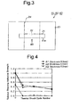
- the samples A1, A2, and A3 were respectively block-like neodymium magnets 21 (61.5 mm (length) ⁇ 7.9 mm (width) ⁇ 2.5 mm (thickness)) and adhered to a steel plate 23 by adhesive agents (adhesive agent layer 22) having different layer thicknesses.
- the adhering area between the steel plate 23 and the neodymium magnet 21 of each sample A1, A2, and A3 corresponds to the area of a longitudinally middle portion of the neodymium magnet 21 (35 mm ⁇ 7.9 mm).
- the neodymium magnet 21 and the steel plate 23 having no grooves are adhered by the adhesive agent, i.e., the adhesive agent layer 22 having a thickness of 0.03 mm.
- an adhesive agent groove 24 (shown by the broken lines in Fig. 3) having a width of 35 mm and a depth that is uniform was formed in the steel plate 23.
- the adhesive agent groove 24 was filled with the adhesive agent (adhesive agent layer 22) to adhere the neodymium magnet to the steel plate 23.
- the depth of the adhesive agent groove 24 was 0.1 mm for the sample A2 and 0.2 mm for the sample A3. Accordingly, the adhesive agent layer 22 of the sample A2 had a thickness 0.1 mm, and the adhesive agent layer 22 of the sample A3 had a thickness of 0.2 mm.
- the sample A1 corresponded to the adhesion structure of the prior art, and the sample A2 corresponded to the adhesion structure of the first embodiment.
- Fig. 4 is a graph showing the relationship between the thermal shock cycle number (horizontal axis) and the relative shearing adhesive strength (vertical axis) in the samples A1, A2, and A3.
- thermal shock cycle number refers to the number of times a thermal shock test, in which the temperature was changed in a range of -40°C to 120°C, was repeated.
- relative shearing adhesive strength refers to the ratio of the initial shearing adhesive strength during repetition of the thermal shock cycles and the shearing adhesive strength of each sample when the initial shearing adhesive strength of the sample A2 is defined as 1.
- the relative shearing adhesive strength of the samples A2 and A3 is about two times greater than that of the sample Al.
- the relative shearing adhesive strength of the sample Al quickly decreases to 0, whereas the relative shearing adhesive strength shifts to a range of 0.2 to 0.5.
- the same characteristics as the sample A2 was obtained when the thickness of the adhesive agent layer 22 was 0.05 mm.
- Fig. 5 shows the results of comparing the sample A2 and samples A4, A5, and A6 having adhering areas that differ from that of the sample A2.
- the width of the adhesive agent groove 24 in the samples A4, A5, and A6 were 25 mm, 45 mm, and 55 mm, respectively.
- the adhering area of the sample A4 (groove width 25 mm) was 25 mm ⁇ 7.9 mm
- the adhering area of the sample A5 (groove width 45 mm) was 45 mm ⁇ 7.9 mm.
- the adhering area of the sample A6 (groove width 55 mm) was 55 mm ⁇ 7.9 mm.
- relative shearing adhesive strength refers to the ratio of the initial shearing adhesive strength during repetition of the thermal shock cycles and the shearing adhesive strength of each sample when the initial shearing adhesive strength of the sample A2 is defined as 1.
- the letter L in Fig. 5 indicates life cycle number with respect to the thermal shock cycle number.
- the relative shearing adhesive strength was in the order of sample A2 > sample A4 > sample A5 > sample A6.
- the relative shearing adhesive strength of the sample A2 is greater than that of the sample A4.
- the relative shearing adhesive strength decreases as the groove width increases.
- the sample A2 had the greatest relative shearing adhesive strength and obtained the optimal results.
- the adhesion structure 11 of the first embodiment has the advantages described below.
- the adhesive agent groove 14, which determines the thickness T1 of the adhesive agent layer 15, is formed so that the adhesive agent layer 15 absorbs the shearing stress produced at the interfaces I1 and I2 due to the linear expansion difference between the rotor shaft 12 and the neodymium magnet 13. Accordingly, the adhesive agent groove 14 determines the thickness T1 of the adhesive agent layer 15, which absorbs the shearing stress applied to the adhesive agent layer 15. This effectively suppresses exfoliation of the adhesive agent layer 15.
- a process for forming the adhesive agent groove 14 is necessary in the adhesion structure 11 of the first embodiment. This process is not necessary in the adhering structure of the prior art. However, the process is simpler than the process in which a resin mold is applied around the neodymium magnet 13. Accordingly, the adhesion structure 11 is formed more easily.
- the depth of the adhesive agent groove 14 is 0.1 mm. This enables the adhesive agent layer 15 to have elasticity that absorbs the shearing force applied to the interfaces I1 and I2 without decreasing the adhesive strength of the adhesive agent layer 15.
- the adhesive agent groove 14 is formed in the outer surface of the rotor shaft 12.
- the adhesive agent adheres the bottom surface 14a of the adhesive agent groove 14 to the neodymium magnets 13. Accordingly, the thickness T1 of the adhesive agent layer 15 is determined in accordance with the depth of the adhesive agent groove 14.
- the adhesive agent groove 14 extends along the entire circumference of the rotor shaft 12. Accordingly, the plurality of neodymium magnets 13 are adhered to the rotor shaft 12 by the single adhesive agent groove 14. Further, the adhesive agent groove 14 that extends along the entire circumference of the cylindrical rotor shaft 12 may easily be machined by a lathe.
- each neodymium magnet 13 and the outer surface of the rotor shaft 12 are curved in the same manner, and the bottom surface 14a of the adhesive agent groove 14 is concentric to the outer surface of the rotor shaft 12.
- every section of the adhesive agent layer 15 in the adhesive agent groove 14 has the same thickness. Accordingly, every section of the adhesive agent layer 15 has elasticity.that absorbs the shearing force applied to the interfaces I1 and I2 without decreasing the adhesive strength. This adheres the rotor shaft 12 and the neodymium magnets 13 in a satisfactory state.
- the linear expansion coefficient of a neodymium magnet is 0 to 0.6 x 10 -6 (planar direction) and the linear expansion coefficient of steel is 11 ⁇ 10 -6 .
- the difference between the linear expansion coefficients is 11 ⁇ 10 -6 to 10.4 ⁇ 10 -6 . Accordingly, by combining materials having a linear expansion coefficient difference that is about the same as the combination of steel and neodymium magnet, or a linear expansion coefficient difference of about 10.0 ⁇ 10 -6 or greater, the advantages of the first embodiment may be obtained.
- the adhesion structure 31 uses neodymium magnets 32 that are shaped differently from the neodymium magnets 13 used for the adhesion structure 11 of the first embodiment.
- the adhesion structure 31 includes a plurality of the neodymium magnets 32.
- Each neodymium magnet 32 has a surface (hereafter referred to as opposing surface) 32a opposed to the rotor shaft 12.
- the radius of curvature of the opposing surface 32a is smaller than the radius of the rotor shaft 12.
- the lateral edges, or contact edges 33, of the opposing surface 32a contact the outer surface of the rotor shaft 12 at portions excluding where the adhesive agent layer is formed. That is, the contact edges 33 contact the outer surface of the rotor shaft 12 along the axial direction of the rotor shaft 12.
- An adhesive agent adhering the neodymium magnets 32 to the outer surface of the rotor shaft 12 forms an adhesive agent layer 34.
- the adhesive agent layer 34 has a maximum thickness T2 at portions corresponding to the laterally central portion of each neodymium magnet 32. Further, the adhesive agent layer 34 has a minimum thickness T3 at portions corresponding to the contact edges 33 of each neodymium magnet 32.
- the thickness T2 is 0.2 mm or less, and the thickness T3 is 0.05 mm or more. More specifically, in the second embodiment, the depth of the adhesive agent groove 14 and the radius of curvature of the opposing surface 32a of the neodymium magnets 32 determine the thicknesses T2 and T3 of the adhesive agent layer 34.
- the neodymium magnet 32 In a state in which the two contact edges 33 of each neodymium magnet 32 contacts the outer surface of the rotor shaft 12, the neodymium magnet 32 is adhered to the rotor shaft 12 by an adhesive agent. In other words, both contact edges 33 of the neodymium magnet 32 always contact the rotor shaft 12. Thus, the neodymium magnet 32 is adhered to the rotor shaft 12 in a stable state.
- the adhesion structure 31 of the second embodiment has the advantages described below.
- each neodymium magnet 32 has a radius of curvature that is smaller than the radius of the rotor shaft 12.
- the thicknesses T2 and T3 of the adhesive agent layer 34 is determined by the depth of the adhesive agent groove 14 and the radius of curvature of the opposing surface 32a in each neodymium magnet 32. Accordingly, the thicknesses T2 and T3 may be adjusted in an optimal manner.
- the present invention may be embodied in an adhesion structure 41 including a rotor shaft 42, which has a polygonal cross-section, and a block-like neodymium magnet 43.
- an adhesive agent groove 44 is formed in the outer surface of the rotor shaft 42.
- An adhesive agent is filled in the adhesive agent groove 44 to adhere the neodymium magnets 43 to the rotor shaft 42.
- the depth of the adhesive agent groove 44 determines the thickness of the adhesive agent layer.
- the adhesive agent groove 14 of the rotor shaft 12 may be eliminated. More specifically, referring to Fig. 8 showing an adhesion structure 51, an adhesive agent is filled in a thickness determining gap formed between the opposing surface 32a of each neodymium magnet 32 and the outer surface of the rotor shaft 12 to adhere the rotor shaft 12 and the neodymium magnet 32.
- the radius of curvature of the opposing surface 32a determines the thickness of the adhesive agent layer 34. More specifically, the radius of curvature of the opposing surface 32a is determined so that 50% of more of the adhesive agent layer 34 has a thickness in the range of 0.05 mm to 0.2 mm.
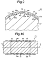
- the adhesive agent groove 14 may be eliminated. More specifically, referring to Fig. 9 showing an adhesion structure 61, an adhesive agent groove 62 is formed in the opposing surface 13a of each neodymium magnet 13 in the axial direction of the rotor shaft 12. An adhesive agent adheres a bottom surface 62a of the adhesive agent groove 62 and outer surface of the rotor shaft 12. In this case, the depth of the adhesive agent groove 62 determines the thickness of the adhesive agent layer.
- the present invention may also be embodied in an adhesion structure 71 that includes spacers 72 as a thickness determining member as shown in Fig. 10. More specifically, a pair of spacers 72 may be used to determine the distance between the rotor shaft 12 and the neodymium magnets 13 and to determine the thickness of the adhesive agent layer. Each of the spacers 72 is annular and fitted to the outer surface of the rotor shaft 12. A wire or tape may also be used in lieu of each spacer 72.
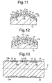
- thickness determining projections 75 may be formed on the outer surface of the rotor shaft 12 (Fig. 11).
- thickness determining projections 76 may be formed on the opposing surface 13a of each neodymium magnet 13 (Fig. 12).
- the thickness determining projections 75 and 76 maintains the distance between the adhered rotor shaft 12 and neodymium magnets 13.
- the projecting lengths of the thickness determining projections 75 and 76 determine the thickness of the adhesive agent layer.
- the thickness determining projections 75 and 76 may be a plurality of bosses formed at predetermined intervals in the axial direction of the rotor shaft 2 or walls extending in the axial direction of the rotor shaft 12.
- a plurality of adhesive agent grooves 14 may be formed in the rotor shaft 12 of the first embodiment at predetermined intervals in the axial direction.
- adhesive agent is filled in each of the adhesive agent grooves 14 to adhere the rotor shaft 12 and the neodymium'magnets 13.
- the adhesive agent groove 14 may be formed only at portions in the outer surface of the rotor shaft 12 that are adhered with the opposing surfaces 13a of the neodymium magnets 13 by an adhesive agent.
- any material may be used to form the rotor shaft 12 and the neodymium magnets 13.
- the adhesive agent groove 14 is formed in the rotor shaft 12 of the inner rotor type brushless DC motor, and the adhesive agent layer 15 adheres the rotor shaft 12 and the neodymium magnets 13.
- a thickness determining groove may be formed in an inner surface of a rotor for an outer rotor type brushless DC motor.
- the layer thickness determining groove is used to determine the thickness of the adhesive agent layer that adheres the neodymium magnets to the rotor.
- an outer rotor type brushless DC motor may have the thickness determining groove formed in neodymium magnets to determine the thickness of the adhesive agent layer and adhere the magnets to the rotor.
- the present invention may be applied to an adhering structure that adheres neodymium magnets to the inner surface of a stator for a motor.
- an adhesive agent groove may be formed in the inner surface of a stator.
- An adhesive agent is filled in the adhesive agent groove to adhere neodymium magnets to the stator.
- An adhesion structure of a motor that adheres a rotor (12) having a first linear expansion coefficient and a magnet (13) having a second linear expansion coefficient, which differs from the first linear expansion coefficient, with an adhesive agent.
- the adhesion structure includes a thickness determining groove (14) extending parallel to the axis of the rotor and arranged on the rotor in order to determine the thickness of an adhesive agent layer, which is formed from the adhesive agent.
- the thickness determining groove absorbs shearing stress produced by the difference between the first and second linear expansion coefficients at a surface adhered to the magnet. This effectively suppresses exfoliation of the adhesive agent layer.
Landscapes
- Engineering & Computer Science (AREA)
- Power Engineering (AREA)
- Manufacturing & Machinery (AREA)
- Permanent Field Magnets Of Synchronous Machinery (AREA)
- Iron Core Of Rotating Electric Machines (AREA)
Abstract
Description
Claims (20)
- An adhesion structure for a motor for adhering a rotor or a stator having a first linear expansion coefficient and a magnet having a second linear expansion coefficient, which differs from the first linear expansion coefficient, to one another, the adhesion structure comprising an adhesive agent for forming an adhesive agent layer, the adhesion structure characterized by
a thickness determining means extending in an axial direction of the rotor and arranged on either one of the magnet and the rotor or the stator, the thickness determining means determining the thickness of the adhesive agent layer formed from the adhesive agent so as to absorb shearing stress produced by the difference between the first and second linear expansion coefficients at a surface adhered to the magnet. - The adhesion structure according to claim 1, characterized in that the thickness of the adhesive agent layer determined by the thickness determining means is in the range of 0.05 mm to 0.2 mm.
- The adhesion structure according to claim 2, characterized in that the thickness of the adhesive agent layer is 0.05 mm to 0.2 mm in 50% to 100% of the adhesive agent layer.
- The adhesion structure according to claim 1, characterized in that the thickness of the adhesive agent layer determined by the thickness determining means is in the range of 0.075 mm to 0.175 mm.
- The adhesion structure according to claim 1, characterized in that the thickness of the adhesive agent layer determined by the thickness determining means is in the range of 0.1 mm to 0.15 mm.
- The adhesion structure according to claim 1, characterized in that the thickness determining means is formed on an outer surface of the rotor or an inner surface of the stator and includes a thickness determining groove filled with the adhesive agent.
- The adhesion structure according to claim 6, characterized in that the thickness determining groove extends along the entire outer surface of the rotor or the inner surface of the stator.
- The adhesion structure according to claim 6, characterized in that the thickness determining groove has a depth in the range of 0.05 mm to 0.2 mm.
- The adhesion structure according to claim 6, characterized in that the thickness determining groove has a depth in the range of 0.075 mm to 0.175 mm.
- The adhesion structure according to claim 6, characterized in that the thickness determining groove has a depth in the range of 0.1 mm to 0.15 mm.
- The adhesion structure according to claim 1, characterized in that the thickness determining means includes:an opposing surface defined on a surface of the magnet or the stator opposed to the rotor and having a radius of curvature that is smaller than the radius of the rotor or the stator; anda gap defined between the rotor or the stator and the opposing surface of the magnet.
- The adhesion structure according to any one of claims 1 to 11, characterized in that the difference between the first linear expansion coefficient and the second linear expansion coefficient is greater than 10.4 × 10⁻⁶.
- The adhesion structure according to claim 12, characterized in that the rotor or the stator is made of steel, and the magnet is made of a rare earth element material.
- The adhesion structure according to any one of claims 1 to 13, characterized in that the thickness determining means is arranged to correspond with 48% or more of a surface of the magnet opposed to the rotor or the stator in the axial direction of the rotor or the stator.
- The adhesion structure according to any one of claims 1 to 13, characterized in that 48% to 65% of a surface of the magnet opposed to the rotor or the stator is adhered to the rotor or the stator by the adhesive agent layer.
- The adhesion structure according to claim 1, characterized in that the thickness determining means includes a thickness determining groove formed on a surface of the magnet opposed to the rotor or the stator and filled with the adhesive agent.
- The adhesion structure according to claim 1, characterized in that the thickness determining means includes a projection for determining the thickness of the adhesive agent layer with the projection formed integrally with one of the magnet and the rotor or stator.
- The adhesion structure according to claim 1, characterized in that the thickness determining means includes a thickness determining member arranged between the magnet and the rotor or stator.
- The adhesion structure according to claim 1, characterized in that the adhesive agent layer has a uniform thickness.
- A motor comprising a rotor having a first linear expansion coefficient, and a magnet adhered to the rotor by an adhesive agent forming an adhesive agent layer, the magnet having a second linear expansion coefficient that differs from the first linear expansion coefficient, the motor characterized by
a thickness determining means extending in an axial direction of the rotor and arranged on either one of the rotor or the magnet, the thickness determining means determining the thickness of the adhesive agent layer formed from the adhesive agent so as to absorb shearing stress produced by the difference between the first and second linear expansion coefficients at a surface adhered to the magnet.
Applications Claiming Priority (2)
| Application Number | Priority Date | Filing Date | Title |
|---|---|---|---|
| JP2002351754 | 2002-12-03 | ||
| JP2002351754A JP4267309B2 (en) | 2002-12-03 | 2002-12-03 | Adhesive structure |
Publications (3)
| Publication Number | Publication Date |
|---|---|
| EP1427088A2 true EP1427088A2 (en) | 2004-06-09 |
| EP1427088A3 EP1427088A3 (en) | 2006-01-11 |
| EP1427088B1 EP1427088B1 (en) | 2009-03-04 |
Family
ID=32310710
Family Applications (1)
| Application Number | Title | Priority Date | Filing Date |
|---|---|---|---|
| EP03027646A Expired - Lifetime EP1427088B1 (en) | 2002-12-03 | 2003-12-02 | Adhesion structure for a motor |
Country Status (4)
| Country | Link |
|---|---|
| US (1) | US7116026B2 (en) |
| EP (1) | EP1427088B1 (en) |
| JP (1) | JP4267309B2 (en) |
| DE (1) | DE60326423D1 (en) |
Cited By (9)
| Publication number | Priority date | Publication date | Assignee | Title |
|---|---|---|---|---|
| EP1598558A1 (en) * | 2004-05-18 | 2005-11-23 | Pfeiffer Vacuum GmbH | Oil sealed vane type rotary vacuum pump |
| WO2007042473A1 (en) * | 2005-10-11 | 2007-04-19 | Robert Bosch Gmbh | Rotor for an electrical machine |
| DE102006049866A1 (en) * | 2006-10-23 | 2008-04-30 | Siemens Ag | Electrical machine i.e. permanently excited electrical machine, for use in machine tool, has stator with winding system, and permanent magnets fixed and positioned at surface of rotor by fixing material |
| WO2011000617A3 (en) * | 2009-07-01 | 2011-11-10 | Siemens Aktiengesellschaft | Rotor and method for manufacturing a rotor of an electric machine |
| WO2012031923A1 (en) * | 2010-09-08 | 2012-03-15 | Siemens Aktiengesellschaft | Rotor for an electrical machine |
| JP2015130780A (en) * | 2013-12-06 | 2015-07-16 | 株式会社デンソー | Rotor and rotary electric machine using the same |
| EP3531538A1 (en) * | 2018-02-23 | 2019-08-28 | Nidec Corporation | Rotor assembly, motor, blower, and vacuum cleaner |
| WO2022017721A1 (en) * | 2020-07-24 | 2022-01-27 | Sew-Eurodrive Gmbh & Co. Kg | Electric motor having a rotor |
| DE102004035675B4 (en) * | 2004-07-22 | 2025-05-28 | Sew-Eurodrive Gmbh & Co Kg | Rotor shaft, synchronous motor, brushless DC motor |
Families Citing this family (29)
| Publication number | Priority date | Publication date | Assignee | Title |
|---|---|---|---|---|
| JP4267309B2 (en) * | 2002-12-03 | 2009-05-27 | 株式会社ジェイテクト | Adhesive structure |
| JP5051275B2 (en) * | 2003-06-13 | 2012-10-17 | 株式会社安川電機 | Permanent magnet motor |
| JP2006174655A (en) * | 2004-12-17 | 2006-06-29 | Nidec Sankyo Corp | Motor and manufacturing method thereof |
| JP2006204052A (en) * | 2005-01-24 | 2006-08-03 | Nsk Ltd | Electric motor |
| US7638914B2 (en) * | 2006-02-01 | 2009-12-29 | Sierra Madre Mktg Group | Permanent magnet bonding construction |
| EP1850454B1 (en) * | 2006-04-24 | 2011-06-22 | Inventio AG | Traction drive for elevator |
| JP4930127B2 (en) * | 2007-03-20 | 2012-05-16 | パナソニック株式会社 | Surface magnet type rotor and manufacturing method thereof |
| US20090058202A1 (en) * | 2007-08-31 | 2009-03-05 | Young-Chun Jeung | Rotor of brushless direct-current motor |
| JP2009011019A (en) * | 2007-06-26 | 2009-01-15 | Minebea Co Ltd | Rotor structure |
| EP3540915B1 (en) * | 2007-11-15 | 2022-05-11 | Mitsubishi Electric Corporation | Permanent magnet type rotating electrical machine and electric power steering device |
| JP2010239800A (en) * | 2009-03-31 | 2010-10-21 | Mitsubishi Electric Corp | Rotor for rotating electrical machine and method for manufacturing the same |
| JP2012120366A (en) * | 2010-12-02 | 2012-06-21 | Mitsubishi Electric Corp | Permanent magnet motor, magnet for the same, and structure for bonding magnet for the same |
| TW201233005A (en) * | 2011-01-18 | 2012-08-01 | Yen Shen Electric Ind Co Ltd | Motor rotor capable of being separately applied to two magnetic units |
| EP2549631B1 (en) * | 2011-07-22 | 2021-07-14 | LG Innotek Co., Ltd. | Holding structure of sensing magnet for EPS motor |
| JP5963479B2 (en) * | 2012-03-07 | 2016-08-03 | 三菱電機株式会社 | Magnet mounted rotor |
| JP2015073355A (en) * | 2013-10-02 | 2015-04-16 | 株式会社安川電機 | Rotor of rotary electric machine, rotary electric machine, and magnetization device for the same |
| EP2930825A1 (en) * | 2014-04-11 | 2015-10-14 | Siemens Aktiengesellschaft | Mounting of permanent magnets on a rotor of an electric machine |
| JP2015204733A (en) * | 2014-04-16 | 2015-11-16 | 日本電産サンキョー株式会社 | motor |
| JP6715625B2 (en) * | 2016-03-17 | 2020-07-01 | アイシン・エィ・ダブリュ株式会社 | Rotor for rotating electric machine |
| JP6464114B2 (en) * | 2016-05-20 | 2019-02-06 | ファナック株式会社 | Rotor structure of rotating electric machine and rotating electric machine |
| CN106253521A (en) * | 2016-08-23 | 2016-12-21 | 黄石东贝电器股份有限公司 | A kind of magneto Surface Mount rotor |
| CN106505764B (en) * | 2016-11-18 | 2023-07-14 | 珠海格力节能环保制冷技术研究中心有限公司 | Rotor structure, motor and compressor |
| FR3069391B1 (en) * | 2017-07-24 | 2021-12-31 | Valeo Equip Electr Moteur | ROTOR WITH PERMANENT MAGNET FOR ELECTRIC MOTOR AND CORRESPONDING AIR PULSE DEVICE |
| JP2019083650A (en) * | 2017-10-31 | 2019-05-30 | 三菱電機株式会社 | Rotor, manufacturing method of rotor, and rotary electric machine |
| US11532961B2 (en) * | 2018-09-21 | 2022-12-20 | Steering Solutions Ip Holding Corporation | Pole lobed rotor core |
| KR102875013B1 (en) * | 2019-07-26 | 2025-10-22 | 엘지이노텍 주식회사 | Motor |
| CN113364180B (en) * | 2021-06-21 | 2022-03-08 | 珠海格力电器股份有限公司 | Rotor structure and motor with same |
| WO2023106239A1 (en) * | 2021-12-10 | 2023-06-15 | ソニーグループ株式会社 | Adhesive configuration, electronic equipment, and adhesion method |
| CN119519179A (en) * | 2025-01-17 | 2025-02-25 | 瑞声光电科技(常州)有限公司 | Stepper Motor |
Family Cites Families (15)
| Publication number | Priority date | Publication date | Assignee | Title |
|---|---|---|---|---|
| DE2637706A1 (en) * | 1976-08-21 | 1978-02-23 | Bosch Gmbh Robert | SEGMENT MAGNET |
| JPS60102854A (en) | 1983-11-07 | 1985-06-07 | Sanyo Electric Co Ltd | Sealed motor compressor |
| JPS62193540A (en) * | 1986-02-17 | 1987-08-25 | Fanuc Ltd | Permanent magnet stator |
| JPH07107687A (en) | 1993-09-30 | 1995-04-21 | Toyota Motor Corp | Rotor |
| JP3287113B2 (en) * | 1994-05-23 | 2002-05-27 | 株式会社安川電機 | Manufacturing method of permanent magnet type rotor |
| JPH08154351A (en) * | 1994-11-29 | 1996-06-11 | Daido Steel Co Ltd | Magnet rotor |
| BR9504773A (en) * | 1995-10-04 | 1997-09-02 | Brasil Compressores Sa | Rotor with permanent magnets for electric motor |
| JPH09140077A (en) * | 1995-11-17 | 1997-05-27 | Sanmei Denki Kk | Rotor in rotating machine |
| JPH10174318A (en) * | 1996-12-05 | 1998-06-26 | Asmo Co Ltd | Small-sized motor |
| US6078121A (en) * | 1997-02-21 | 2000-06-20 | Emerson Electric Co. | Rotor assembly for a rotating machine |
| JPH1189141A (en) | 1997-09-09 | 1999-03-30 | Mitsubishi Electric Corp | Permanent magnet rotor and manufacturing method thereof |
| WO2000014859A1 (en) * | 1998-09-02 | 2000-03-16 | Empresa Brasileira De Compressores S.A. - Embraco | An electric motor rotor and a process for producing an electric motor rotor |
| JP2002234449A (en) | 2001-02-07 | 2002-08-20 | Nsk Ltd | Electric power steering device |
| US6552459B2 (en) * | 2001-03-20 | 2003-04-22 | Emerson Electric Co. | Permanent magnet rotor design |
| JP4267309B2 (en) * | 2002-12-03 | 2009-05-27 | 株式会社ジェイテクト | Adhesive structure |
-
2002
- 2002-12-03 JP JP2002351754A patent/JP4267309B2/en not_active Expired - Fee Related
-
2003
- 2003-12-02 US US10/724,831 patent/US7116026B2/en not_active Expired - Lifetime
- 2003-12-02 EP EP03027646A patent/EP1427088B1/en not_active Expired - Lifetime
- 2003-12-02 DE DE60326423T patent/DE60326423D1/en not_active Expired - Lifetime
Cited By (15)
| Publication number | Priority date | Publication date | Assignee | Title |
|---|---|---|---|---|
| EP1598558A1 (en) * | 2004-05-18 | 2005-11-23 | Pfeiffer Vacuum GmbH | Oil sealed vane type rotary vacuum pump |
| DE102004035675B4 (en) * | 2004-07-22 | 2025-05-28 | Sew-Eurodrive Gmbh & Co Kg | Rotor shaft, synchronous motor, brushless DC motor |
| WO2007042473A1 (en) * | 2005-10-11 | 2007-04-19 | Robert Bosch Gmbh | Rotor for an electrical machine |
| CN101288217B (en) * | 2005-10-11 | 2012-07-11 | 罗伯特·博世有限公司 | Rotor for an electrical machine |
| DE102006049866A1 (en) * | 2006-10-23 | 2008-04-30 | Siemens Ag | Electrical machine i.e. permanently excited electrical machine, for use in machine tool, has stator with winding system, and permanent magnets fixed and positioned at surface of rotor by fixing material |
| US8847453B2 (en) | 2009-07-01 | 2014-09-30 | Siemens Aktiengesellschaft | Rotor and method for manufacturing a rotor of an electric machine |
| WO2011000617A3 (en) * | 2009-07-01 | 2011-11-10 | Siemens Aktiengesellschaft | Rotor and method for manufacturing a rotor of an electric machine |
| RU2499342C2 (en) * | 2009-07-01 | 2013-11-20 | Сименс Акциенгезелльшафт | Rotor and method to manufacture rotor of electric machine |
| CN103109443A (en) * | 2010-09-08 | 2013-05-15 | 西门子公司 | Rotor for an electrical machine |
| CN103109443B (en) * | 2010-09-08 | 2015-07-01 | 西门子公司 | rotor for motor |
| US9257890B2 (en) | 2010-09-08 | 2016-02-09 | Siemens Aktiengesellschaft | Permanent magnet rotor for an electrical machine |
| WO2012031923A1 (en) * | 2010-09-08 | 2012-03-15 | Siemens Aktiengesellschaft | Rotor for an electrical machine |
| JP2015130780A (en) * | 2013-12-06 | 2015-07-16 | 株式会社デンソー | Rotor and rotary electric machine using the same |
| EP3531538A1 (en) * | 2018-02-23 | 2019-08-28 | Nidec Corporation | Rotor assembly, motor, blower, and vacuum cleaner |
| WO2022017721A1 (en) * | 2020-07-24 | 2022-01-27 | Sew-Eurodrive Gmbh & Co. Kg | Electric motor having a rotor |
Also Published As
| Publication number | Publication date |
|---|---|
| JP2004187411A (en) | 2004-07-02 |
| US20040217664A1 (en) | 2004-11-04 |
| JP4267309B2 (en) | 2009-05-27 |
| EP1427088A3 (en) | 2006-01-11 |
| US7116026B2 (en) | 2006-10-03 |
| DE60326423D1 (en) | 2009-04-16 |
| EP1427088B1 (en) | 2009-03-04 |
Similar Documents
| Publication | Publication Date | Title |
|---|---|---|
| US7116026B2 (en) | Adhesion structure for motor, having thickness determining means | |
| US5961222A (en) | Anti-electrolytic corrosion rolling bearing | |
| US4707630A (en) | Magnetic cover member for magnetic poles of DC motor | |
| EP2843805B1 (en) | Electric motor | |
| JP5486036B2 (en) | Electric motor having a rotor structure for preventing problems due to distortion caused by temperature change and method for manufacturing the same | |
| CN102782989B (en) | Rotor of a rotating electrical machine | |
| JP3449061B2 (en) | DC motor | |
| KR102141793B1 (en) | Method of manufacturing a stator of a permanent magnet synchronous machine and a permanent magnet synchronous machine | |
| EP0154335A2 (en) | Magneto d.c. motor | |
| JP3541793B2 (en) | Cylindrical dynamic damper | |
| EP0942511A2 (en) | Permanent magnet rotor and method of assembly | |
| CN112203878A (en) | Chassis suspension for a motor vehicle | |
| CN103051081B (en) | For the clamp system being fixed on permanent magnet in rotor or stator | |
| CN104471835A (en) | Molded part for pre-fastening a permanent magnet in a rotor or stator, fastening of the permanent magnet by means of a curable medium, and thermal protection of the permanent magnet during the fastening | |
| JPWO2015049967A1 (en) | Permanent magnet embedded rotary electric machine and method for manufacturing the same | |
| WO2014168091A1 (en) | Magnetic encoder and production method therefor | |
| CN107404166B (en) | Rotor structure of rotating electric machine and rotating electric machine | |
| JP6702378B2 (en) | Rotor of permanent magnet surface sticking type rotary machine and manufacturing method thereof | |
| JPH03253249A (en) | Rotor for motor using permanent magnet | |
| KR100212675B1 (en) | Magnet fixing structure of linear motor | |
| EP1798558B1 (en) | Magnetized pulser ring | |
| JPWO2006114890A1 (en) | Outer rotor type motor stator | |
| JP2010104090A (en) | Linear actuator | |
| JP4925720B2 (en) | Mover for linear motor | |
| JPH027841A (en) | Permanent magnet rotor |
Legal Events
| Date | Code | Title | Description |
|---|---|---|---|
| PUAI | Public reference made under article 153(3) epc to a published international application that has entered the european phase |
Free format text: ORIGINAL CODE: 0009012 |
|
| AK | Designated contracting states |
Kind code of ref document: A2 Designated state(s): AT BE BG CH CY CZ DE DK EE ES FI FR GB GR HU IE IT LI LU MC NL PT RO SE SI SK TR |
|
| AX | Request for extension of the european patent |
Extension state: AL LT LV MK |
|
| PUAL | Search report despatched |
Free format text: ORIGINAL CODE: 0009013 |
|
| AK | Designated contracting states |
Kind code of ref document: A3 Designated state(s): AT BE BG CH CY CZ DE DK EE ES FI FR GB GR HU IE IT LI LU MC NL PT RO SE SI SK TR |
|
| AX | Request for extension of the european patent |
Extension state: AL LT LV MK |
|
| 17P | Request for examination filed |
Effective date: 20060710 |
|
| AKX | Designation fees paid |
Designated state(s): DE FR GB |
|
| 17Q | First examination report despatched |
Effective date: 20060828 |
|
| RAP1 | Party data changed (applicant data changed or rights of an application transferred) |
Owner name: JTEKT CORPORATION |
|
| RIN1 | Information on inventor provided before grant (corrected) |
Inventor name: HASE, ATSUSHI Inventor name: KUWABARA, HIROFUMI Inventor name: KINOSHITA, YASUO |
|
| GRAP | Despatch of communication of intention to grant a patent |
Free format text: ORIGINAL CODE: EPIDOSNIGR1 |
|
| RTI1 | Title (correction) |
Free format text: ADHESION STRUCTURE FOR A MOTOR |
|
| RIN1 | Information on inventor provided before grant (corrected) |
Inventor name: KINOSHITA, YASUO Inventor name: KUWABARA, HIROFUMI Inventor name: HASE, ATSUSHI |
|
| GRAS | Grant fee paid |
Free format text: ORIGINAL CODE: EPIDOSNIGR3 |
|
| GRAA | (expected) grant |
Free format text: ORIGINAL CODE: 0009210 |
|
| AK | Designated contracting states |
Kind code of ref document: B1 Designated state(s): DE FR GB |
|
| REG | Reference to a national code |
Ref country code: GB Ref legal event code: FG4D |
|
| REF | Corresponds to: |
Ref document number: 60326423 Country of ref document: DE Date of ref document: 20090416 Kind code of ref document: P |
|
| PLBE | No opposition filed within time limit |
Free format text: ORIGINAL CODE: 0009261 |
|
| STAA | Information on the status of an ep patent application or granted ep patent |
Free format text: STATUS: NO OPPOSITION FILED WITHIN TIME LIMIT |
|
| 26N | No opposition filed |
Effective date: 20091207 |
|
| GBPC | Gb: european patent ceased through non-payment of renewal fee |
Effective date: 20091202 |
|
| PG25 | Lapsed in a contracting state [announced via postgrant information from national office to epo] |
Ref country code: GB Free format text: LAPSE BECAUSE OF NON-PAYMENT OF DUE FEES Effective date: 20091202 |
|
| REG | Reference to a national code |
Ref country code: FR Ref legal event code: PLFP Year of fee payment: 13 |
|
| REG | Reference to a national code |
Ref country code: FR Ref legal event code: PLFP Year of fee payment: 14 |
|
| REG | Reference to a national code |
Ref country code: FR Ref legal event code: PLFP Year of fee payment: 15 |
|
| REG | Reference to a national code |
Ref country code: FR Ref legal event code: PLFP Year of fee payment: 18 |
|
| PGFP | Annual fee paid to national office [announced via postgrant information from national office to epo] |
Ref country code: DE Payment date: 20201118 Year of fee payment: 18 Ref country code: FR Payment date: 20201112 Year of fee payment: 18 |
|
| REG | Reference to a national code |
Ref country code: DE Ref legal event code: R119 Ref document number: 60326423 Country of ref document: DE |
|
| PG25 | Lapsed in a contracting state [announced via postgrant information from national office to epo] |
Ref country code: DE Free format text: LAPSE BECAUSE OF NON-PAYMENT OF DUE FEES Effective date: 20220701 |
|
| PG25 | Lapsed in a contracting state [announced via postgrant information from national office to epo] |
Ref country code: FR Free format text: LAPSE BECAUSE OF NON-PAYMENT OF DUE FEES Effective date: 20211231 |