EP1426694A2 - Device for a valve - Google Patents
Device for a valve Download PDFInfo
- Publication number
- EP1426694A2 EP1426694A2 EP03025136A EP03025136A EP1426694A2 EP 1426694 A2 EP1426694 A2 EP 1426694A2 EP 03025136 A EP03025136 A EP 03025136A EP 03025136 A EP03025136 A EP 03025136A EP 1426694 A2 EP1426694 A2 EP 1426694A2
- Authority
- EP
- European Patent Office
- Prior art keywords
- moving part
- valve
- fixed part
- closing
- closing member
- Prior art date
- Legal status (The legal status is an assumption and is not a legal conclusion. Google has not performed a legal analysis and makes no representation as to the accuracy of the status listed.)
- Granted
Links
- 238000013016 damping Methods 0.000 claims abstract description 16
- 239000000463 material Substances 0.000 abstract description 9
- 238000009423 ventilation Methods 0.000 description 12
- 239000006096 absorbing agent Substances 0.000 description 2
- 230000005540 biological transmission Effects 0.000 description 2
- 239000000853 adhesive Substances 0.000 description 1
- 230000001070 adhesive effect Effects 0.000 description 1
- 238000010276 construction Methods 0.000 description 1
- 230000001419 dependent effect Effects 0.000 description 1
- 238000009434 installation Methods 0.000 description 1
- 238000004519 manufacturing process Methods 0.000 description 1
- 239000000203 mixture Substances 0.000 description 1
- 230000002093 peripheral effect Effects 0.000 description 1
- 230000035945 sensitivity Effects 0.000 description 1
- 230000035939 shock Effects 0.000 description 1
- 239000000126 substance Substances 0.000 description 1
Images


Classifications
-
- F—MECHANICAL ENGINEERING; LIGHTING; HEATING; WEAPONS; BLASTING
- F24—HEATING; RANGES; VENTILATING
- F24C—DOMESTIC STOVES OR RANGES ; DETAILS OF DOMESTIC STOVES OR RANGES, OF GENERAL APPLICATION
- F24C15/00—Details
- F24C15/20—Removing cooking fumes
- F24C15/2021—Arrangement or mounting of control or safety systems
-
- F—MECHANICAL ENGINEERING; LIGHTING; HEATING; WEAPONS; BLASTING
- F24—HEATING; RANGES; VENTILATING
- F24F—AIR-CONDITIONING; AIR-HUMIDIFICATION; VENTILATION; USE OF AIR CURRENTS FOR SCREENING
- F24F13/00—Details common to, or for air-conditioning, air-humidification, ventilation or use of air currents for screening
- F24F13/08—Air-flow control members, e.g. louvres, grilles, flaps or guide plates
- F24F13/10—Air-flow control members, e.g. louvres, grilles, flaps or guide plates movable, e.g. dampers
- F24F13/14—Air-flow control members, e.g. louvres, grilles, flaps or guide plates movable, e.g. dampers built up of tilting members, e.g. louvre
- F24F13/1426—Air-flow control members, e.g. louvres, grilles, flaps or guide plates movable, e.g. dampers built up of tilting members, e.g. louvre characterised by actuating means
- F24F2013/1446—Air-flow control members, e.g. louvres, grilles, flaps or guide plates movable, e.g. dampers built up of tilting members, e.g. louvre characterised by actuating means with gearings
Definitions
- the invention relates to a device for a valve in an outlet duct according to the pre-characterizing part of claim 1.
- the invention also relates to an operating member according to the pre-characterizing part of claim 18.
- Valves with an opening and closing valve cover are used in ventilation systems. When the valve cover is open, air can be emitted through an outlet duct.
- valve cover in which the valve cover in an oscillating movement about an axis running transversely to the longitudinal direction of the outlet duct is opened and closed like a door, on closing of the valve a pressure wave occurs in the outlet duct which is then reflected and opens the valve cover again, whereupon it is closed again, a new pressure wave occurs, which is reflected, and the valve cover is opened again, etc.
- the valve cover of the valve either temporarily or continuously, slams to and fro against an end flange contained within the valve.
- a conventional solution to this problem is to use a closing device for closing the valve, comprising a strong spring or the like, which closes the valve cover with a force sufficient to withstand the said pressure wave.
- Natural draught ventilation relies on the fact that warm air rises, so that the difference between outdoor and indoor temperature determines the quality of the ventilation achieved. Cold weather gives good ventilation, but then a counter-draught also occurs in the outlet duct in which cold air and even frost are entrained so that so-called cold creep occurs.
- non-return valves also referred to as cold creep protection
- One problem with non-return valves is that they can keep oscillating between the open and closed position, which causes loud rattling noises.
- a further problem are the undue material stresses that occur when the valve cover slams to and fro.
- An object of the present invention is to prevent high noise levels in a valve.
- a further object of the present invention is to increase the service life of a valve and other parts.
- a device for a valve of the said generic type is characterized in that it comprises means for damping the closing speed of the closing member.
- the advantage of this solution is that a reduced closing speed is obtained, so that the contact between the closing member and the end flange of the valve is less violent, which means that loud rattling noises are prevented.
- a further advantage is that the material stresses are reduced, with the result that the service life of the valve and other parts is substantially increased.
- the means of damping the closing speed preferably comprises a viscous, long-life oil applied in a gap between a fixed part and a moving part connected to the closing member. It has been shown that oil having the aforementioned characteristics is eminently suitable for this purpose.
- the moving part is preferably designed to perform a rotational movement about an axis of rotation. It has proved advantageous to have the moving part perform a rotational movement about an axis of rotation, since it can then be readily adapted to existing solutions.
- the fixed part and the moving part preferably each have an essentially cylindrical surface concentric with the axis of rotation, said surfaces being opposed to one another and the viscous, long-life oil preferably being applied axially in a gap between the cylindrical surfaces.
- the moving part is preferably to a substantial extent inserted into the fixed part.
- the fixed part and the moving part preferably each have an essentially plane surface aligned radially in relation to the axis of rotation, said surfaces being opposed to one another and the viscous, long-life oil preferably being applied radially between the plane surfaces.
- the valve is preferably designed to regulate the air flow from an outlet opening in the outlet duct, the closing member being designed to be closed by means of a spring member and being designed to be operated by an operating member comprising the fixed part and the moving part.
- This embodiment has proved particularly advantageous in the case of kitchen ventilation.
- One advantage is that the damping means is easily accessible, since the means is situated in the operating member and this is generally easily accessible.
- the fixed part and the moving part are preferably arranged in an opening between the outside and inside of a fan housing.
- One advantage of this arrangement is that the device is easy to fit to existing kitchen range hoods, since only the turning element needs to be removed.
- the fixed part and the moving part are arranged inside the control element.
- One advantage with this arrangement is that the device does not take up any additional space. This embodiment may be used, for preference, in new production.
- the fixed part and the moving part are arranged between the control element and the valve.
- the arrangement of the fixed part and the moving part is done for practical and installation reasons and is not dependent upon the design of the operating member, and the design of the valve and this embodiment may be preferable in certain design types.
- the fixed part and the moving part are arranged on the axis of rotation of the closing member.
- the valve is preferably a non-return valve. This solution may be of particular advantage in the case of natural draught ventilation.
- the non-return valve preferably comprises two closing members, together with two fixed parts and two moving parts, each fixed part and each moving part being arranged on opposite sides of the axis of rotation of each closing member.
- the non-return valve is preferably located in the outlet duct. This arrangement is advantageous in preventing cold creep.
- the invention also provides an operating member of the aforementioned generic type, characterized by means for damping the rotational movement.
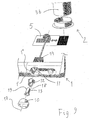
- a valve 2 comprises a valve cover 5, and a pipe stub 7, which carries the valve cover 5.
- a valve is shown in EP 0 422 316 which is hereby incorporated by virtue of this reference.
- the valve cover 5 is pivotally connected by way of a hinge connection to an end flange 8 of the pipe stub 7.
- the valve cover 5 is furthermore designed so that in the closed position of the valve 2 it covers the opening of the pipe stub 7 in that an outer peripheral part comes to bear against an inner part of the annular surface of the end flange 8.
- the valve 2 is suitably fixed in its entirety to a fan housing 1, Fig. 1, with the unflanged end of the pipe stub 7 connected to an outlet duct 3b of a central ventilation system.
- the term fan housing relates to all types of devices in kitchen ventilation including kitchen range hoods.
- valve cover is designed to be opened by means of an operating member 9 comprising a turning element 10, a rod 11, a fixed part 12, a moving part 13, and a control element 14.
- an operating member 9 comprising a turning element 10, a rod 11, a fixed part 12, a moving part 13, and a control element 14.
- the turning element 10, the rod 11, the fixed part 12, the moving part 13 and the control element 14 are arranged, essentially concentrically, around an axis of rotation 17.
- the turning element 10 is fitted in an opening on the outside 1' of the fan housing 1, the fixed part 12 and the moving part 13 are located in the opening essentially between the outside 1' and the inside 1'' of the fan housing 1, the control element 14 is fixed to the inside 1'' of the fan housing 1, and the rod 11 is placed centrally right through the control element 14 and extends through the fixed part 12 and the moving part 13 to the opening in the outside 1' of the fan housing 1.
- the turning element 10 is connected to the moving part 13, the rod 11 is concentrically connected to the turning element 10 and via a linkage is connected to the valve cover 5, and the control element 14 is connected to the rod 11.
- the fixed part 12 and the moving part 13 each have a cylindrical surface 18,19 essentially concentric with the axis of rotation 17 and in opposition to one another, the moving part 13 being substantially inserted into the fixed part 12 and a film of viscous, long-life oil being applied axially in a gap between the cylindrical surfaces 18, 19.
- the fixed part 12 may be inserted into the moving part 13.
- the control element 14 comprises a timer control and a spring member 15, such as a coil spring, although other types of spring may be used.
- the valve cover 5 is opened by manually turning the turning element 10 (clockwise), the rod 11 and the moving part 13 being turned synchronously with the turning element 10 so that, via a linkage between the rod 11 and the valve cover 5, the valve cover 5 is opened like a door in a swivelling movement about the axis of rotation 17, which runs transversely to the longitudinal direction of the outlet duct 3b.
- the control element 14 controls the position of the valve cover 5 in such a way that the valve cover 5, via a linkage, is opened into an open position by manually turning the turning element 10 until the timer is switched on, thereby tensioning the spring member 15.
- the desired time for which the valve cover 5 will be in the open position is adjusted by the timer by turning the turning element 10 to the desired position.
- the timer shuts off, with the result that the spring member 15 closes the valve cover 5 under spring force.
- the viscous, long-life oil that is applied axially between the cylindrical surfaces 18, 19 gives rise to increased resistance between the cylindrical surfaces 18, 19, when turning the moving part 13, especially when closing the valve cover 5.
- the viscous, long-life oil is of a quality such that under slow movements it generates little resistance and under rapid movements it generates great resistance.
- the viscous, long-life oil applied axially between the cylindrical surfaces 18, 19 gives rise to a shear force opposed to the spring force as the moving part 13 rotates inside the fixed part 12, thereby damping the closing speed of the valve cover 5.
- These characteristics give rise to such a strong resistance that the closing speed of the valve cover 5 is damped to a speed conducive to the purpose, so that loud rattling noises are avoided and material stresses are reduced, but the spring force that keeps the valve cover 5 closed is maintained.
- the viscous, long-life oil is of the type commercially available under the designation adhering chain oil, adhesive chain oil or wax oil, which is normally used for high-speed drive chains. Other types of chemical compositions having similar characteristics may also be used.
- the fixed part 12 and the moving part 13 are located inside the control element 14.
- the fixed part 12 and the moving part 13 each have an essentially plane surface 18, 19 aligned radially in relation to the axis of rotation 17, said surfaces being opposed to one another and the viscous, long-life oil being applied radially between the plane surfaces 18, 19.
- the viscous, long-life oil that is applied radially between the plane surfaces 18, 19 correspondingly gives rise to increased resistance between the plane surfaces 18, 19, when turning the moving part 13, especially when closing the valve cover 5.
- the fixed part 12 and the moving part 13 are located between the control element 14 and the valve 2.
- the fixed part 12 and the moving part 13 each have an essentially cylindrical surface 18, 19 concentric with the axis of rotation 17, said surfaces being opposed to one another, the moving part 13 is substantially inserted into the fixed part 12 and a film of viscous, long-life oil is applied axially in a gap between the cylindrical surfaces 18, 19.
- the viscous, long-life oil that is applied axially between the cylindrical surfaces 18, 19 correspondingly gives rise to increased resistance between the cylindrical surfaces 18, 19, when turning the moving part 13, especially when closing the valve cover 5.
- An alternative to the third embodiment is to locate the fixed part 12 and the moving part 13 on the rod 11 between the control element 14 and the valve 2, instead of locating said parts by the control element.
- a further alternative to the third embodiment is to connect the fixed part 12 and the moving part 13 to the axis about which the swivelling valve cover is pivotally connected instead of locating said parts by the control element or on the rod.
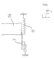
- the valve 2 consists of a non-return valve according to Fig. 6, which is used in a housing with natural draught and relying on the fact that warm air rises, so that the difference between the outdoor and indoor temperature determined the quality of the ventilation obtained. Cold weather gives good ventilation, but then a counter-draught also occurs in the outlet duct 3b in which cold air and even frost are entrained so that so-called cold creep occurs.
- the non-return valve is used for protection against cold creep.
- the non-return valve is normally located inside the outlet duct 3b, but can also be located in connection with the outlet duct.
- the non-return valve has at least one valve cover 5, but preferably two valve covers 5, as shown in Fig.
- a fixed part 12 and a moving part 13 each have essentially cylindrical surfaces 18, 19 concentric with the axis of rotation 17, said surfaces being opposed to one another.
- the pairs comprising a fixed part 12 and a moving part 13 are arranged on opposite sides of the non-return valve on respective axes of rotation 17.
- Each moving part 13 is substantially inserted into each fixed part 12, and the viscous, long-life oil is applied axially in a gap between the cylindrical surfaces 18, 19.
- the viscous, long-life oil that is applied axially between the cylindrical surfaces 18, 19 correspondingly gives rise to increased resistance between the surface 18 of the fixed part 12 and the surface 19 of the moving part 13 when the moving part 13 is turned, thereby damping the closing speed of the valve cover 5, so that loud rattling noises are avoided and material stresses are reduced.
- a valve operating member comprising a turning element 10 mechanically connected to the valve cover 5 in order to control the latter.
- the turning element 10 also constitutes a part of a rotary flow adjuster for controlling an electric fan.
- the rotary flow adjuster may have both continuously variable adjustment and be adjusted in various stages. The sensitivity when turning a continuously variable flow adjuster is “coarse" and comparable to the frequency adjustment dial on a cheap radio. In the stepped rotary flow adjuster the point of engagement registers very abruptly. It is desirable to achieve a certain inertia when turning, a "better feel".
- viscous, long-life oil is also suited to damping the point of engagement in flow adjusters that are adjusted in different stages as these stages register, and to providing a desirable inertia when turning, both in continuously variable adjustment and with stepped adjustment.
- the means of damping the closing speed of the valve cover consists of a viscous, long-life oil, but any other damping elements are also feasible.
- the means may consist of a gear arrangement located on the valve in such a way that it has a transmission ratio which damps the closing speed of the valve cover.
- the transmission ratio means that the torque on the axis of rotation 17 of the valve due to the spring force is reduced, with the result that the closing speed is reduced.
- a shock absorber for example, may be used in which a piston damps the closing speed of the valve cover.
Landscapes
- Engineering & Computer Science (AREA)
- Chemical & Material Sciences (AREA)
- Combustion & Propulsion (AREA)
- Mechanical Engineering (AREA)
- General Engineering & Computer Science (AREA)
- Air-Flow Control Members (AREA)
- Taps Or Cocks (AREA)
- Lift Valve (AREA)
- Flow Control (AREA)
- Details Of Valves (AREA)
- Check Valves (AREA)
Abstract
Description
Claims (24)
- Device for a valve in an outlet duct (3b), the valve comprising at least one closing member (5) for closing off the outlet duct (3b) and the closing member (5) being moveable between a closed position and an open position, characterized by means for damping the closing speed of the closing member (5).
- Device according to Claim 1, characterized in that said means comprises a viscous, long-life oil applied between at least one fixed part (12) and at least one moving part (13) connected to the closing member (5).
- Device according to Claim 2, characterized in that the moving part (13) is designed to perform a rotational movement about an axis of rotation (17).
- Device according to Claim 3, characterized in that the fixed part (12) and the moving part (13) each have an essentially cylindrical surface (18, 19) concentric with the axis of rotation (17), said surfaces being opposed to one another, and in that the viscous, long-life oil is applied axially in a gap between the cylindrical surfaces (18, 19).
- Device according to Claim 4, characterized in that the moving part (13) is substantially inserted into the fixed part (12).
- Device according to Claim 3, characterized in that the fixed part (12) and the moving part (13) each have an essentially plane surface (18, 19) aligned radially in relation to the axis of rotation (17), said surfaces (18, 19) being opposed to one another, and in that the viscous, long-life oil is applied radially between the plane surfaces (18, 19).
- Device according to any one of Claims 2 to 6, characterized in that the valve (2) is designed to regulate the air flow from an outlet opening (3a) in the outlet duct (3b), in that the closing member (5) is designed to be closed by means of a spring member (15) and designed to be operated by an operating member (9) comprising the fixed part (12) and the moving part (13).
- Device according to Claim 7, characterized in that the operating member (9) comprises a turning element (10) connected to the moving part (13), a rod (11) connected to the turning element and connected via a linkage to the closing member (5), and a control element (14) for controlling the position of the closing member (5).
- Device according to any one of Claims 2 to 8, characterized in that the fixed part (12) and the moving part (13) are arranged in an opening between the outside (1') and inside (1'') of a fan housing (1).
- Device according to Claim 8, characterized in that the fixed part (12) and the moving part (13) are arranged inside the control element (14).
- Device according to Claim 8, characterized in that the fixed part (12) and the moving part (13) are arranged between the control element (14) and the valve (2).
- Device according to any one of Claims 3 to 8, characterized in that the fixed part (12) and the moving part (13) are arranged on the axis of rotation (17) of the closing member (5).
- Device according to any one of Claims 1 to 12, characterized in that the closing member (5) is capable of swivelling between the closed and the open position.
- Device according to any one of Claims 1, 2, 3, 4, 5, 6, 12 or 13, characterized in that the valve (2) is a non-return valve.
- Device according to Claim 14, characterized in that the non-return valve comprises two closing members (5), at least one of these having a fixed part (12) and a moving part (13) connected to the closing member, these parts being arranged on an axis of rotation (17) of the closing member (5).
- Device according to Claim 15, characterized in that a fixed part (12) and a moving part (13) connected to each closing member (5) are arranged by each closing member (5).
- Device according to any one of Claims 14 to 16, characterized in that the non-return valve is located in the outlet duct (3b).
- Operating member comprising a turning element (10) designed to perform a rotational movement, characterized by means for damping the rotational movement.
- Operating member according to Claim 18, characterized in that said means comprise a viscous, long-life oil applied between at least one fixed part (12) and at least one moving part (13) connected to the turning element (10).
- Operating member according to Claim 19, characterized in that the moving part (13) is designed to perform a rotational movement about an axis of rotation (17).
- Operating member according to Claim 20, characterized in that the fixed part (12) and the moving part (13) each have an essentially cylindrical surface (18, 19) concentric with the axis of rotation (17), said surfaces being opposed to one another, and that the viscous, long-life oil is applied axially in a gap between the cylindrical surfaces (18, 19).
- Operating member according to Claim 20, characterized in that the fixed part (12) and the moving part (13) each have an essentially plane surface (18, 19) aligned radially in relation to the axis of rotation (17), said surfaces (18, 19) being opposed to one another, and in that the viscous, long-life oil is applied radially between the plane surfaces (18, 19).
- Operating member according to any one of Claims 18 to 22, characterized in that the operating member comprises a timer control and a spring member (15).
- Operating member according to any one of Claims 18 to 22, characterized in that the operating member comprises a rotary flow adjuster.
Applications Claiming Priority (2)
| Application Number | Priority Date | Filing Date | Title |
|---|---|---|---|
| SE0203460 | 2002-11-21 | ||
| SE0203460A SE524245C2 (en) | 2002-11-21 | 2002-11-21 | Device at damper |
Publications (3)
| Publication Number | Publication Date |
|---|---|
| EP1426694A2 true EP1426694A2 (en) | 2004-06-09 |
| EP1426694A3 EP1426694A3 (en) | 2004-10-13 |
| EP1426694B1 EP1426694B1 (en) | 2017-10-18 |
Family
ID=20289648
Family Applications (1)
| Application Number | Title | Priority Date | Filing Date |
|---|---|---|---|
| EP03025136.7A Expired - Lifetime EP1426694B1 (en) | 2002-11-21 | 2003-11-03 | Device for a valve |
Country Status (4)
| Country | Link |
|---|---|
| EP (1) | EP1426694B1 (en) |
| DK (1) | DK1426694T3 (en) |
| NO (1) | NO324399B1 (en) |
| SE (1) | SE524245C2 (en) |
Cited By (2)
| Publication number | Priority date | Publication date | Assignee | Title |
|---|---|---|---|---|
| EP1630478A1 (en) * | 2004-08-16 | 2006-03-01 | Lg Electronics Inc. | Extractor hood |
| EP2713109A1 (en) * | 2012-09-28 | 2014-04-02 | Electrolux Home Products Corporation N.V. | An exhaust closure system for a cooking oven |
Families Citing this family (1)
| Publication number | Priority date | Publication date | Assignee | Title |
|---|---|---|---|---|
| CN109340193B (en) * | 2018-09-27 | 2020-09-01 | 佛山市顺德区美的洗涤电器制造有限公司 | Air ducts, air drives and cooker hoods |
Family Cites Families (3)
| Publication number | Priority date | Publication date | Assignee | Title |
|---|---|---|---|---|
| US5169121A (en) * | 1990-12-24 | 1992-12-08 | Mitsubishi Electronics America, Inc. | Damper control mechanism |
| DE4425029A1 (en) * | 1994-07-15 | 1996-01-18 | Behr Gmbh & Co | Air damper for heating or air conditioning |
| DE19735916B4 (en) * | 1996-08-30 | 2006-01-12 | Volkswagen Ag | Silenced air damper for a heating or air conditioning system |
-
2002
- 2002-11-21 SE SE0203460A patent/SE524245C2/en not_active IP Right Cessation
-
2003
- 2003-11-03 EP EP03025136.7A patent/EP1426694B1/en not_active Expired - Lifetime
- 2003-11-03 DK DK03025136.7T patent/DK1426694T3/en active
- 2003-11-21 NO NO20035175A patent/NO324399B1/en not_active IP Right Cessation
Cited By (4)
| Publication number | Priority date | Publication date | Assignee | Title |
|---|---|---|---|---|
| EP1630478A1 (en) * | 2004-08-16 | 2006-03-01 | Lg Electronics Inc. | Extractor hood |
| EP2713109A1 (en) * | 2012-09-28 | 2014-04-02 | Electrolux Home Products Corporation N.V. | An exhaust closure system for a cooking oven |
| WO2014048775A1 (en) * | 2012-09-28 | 2014-04-03 | Electrolux Home Products Corporation N. V. | An exhaust closure system for a cooking oven |
| US9857084B2 (en) | 2012-09-28 | 2018-01-02 | Electrolux Home Products Corporation N.V. | Exhaust closure system for a cooking oven |
Also Published As
| Publication number | Publication date |
|---|---|
| DK1426694T3 (en) | 2017-11-20 |
| NO20035175L (en) | 2004-05-24 |
| SE524245C2 (en) | 2004-07-13 |
| SE0203460D0 (en) | 2002-11-21 |
| EP1426694B1 (en) | 2017-10-18 |
| NO324399B1 (en) | 2007-10-01 |
| SE0203460L (en) | 2004-05-22 |
| EP1426694A3 (en) | 2004-10-13 |
| NO20035175D0 (en) | 2003-11-21 |
Similar Documents
| Publication | Publication Date | Title |
|---|---|---|
| US5996132A (en) | Compound torque hinge | |
| US5127876A (en) | Fluid control valve unit | |
| CN111452596B (en) | Air regulating device | |
| CA2714442C (en) | Hinge having a damping device | |
| US5592971A (en) | Single handle mixing valve with flow control device for preventing hammer knock | |
| JPH11508656A (en) | Automatic door closer unit | |
| US20030056328A1 (en) | Dampened hinge system for appliance door | |
| US4523609A (en) | Volume flow or pressure regulating device | |
| EP1371873A1 (en) | Damper | |
| EP1063457A3 (en) | Pendulum valve assembly | |
| JP2004514808A (en) | Door hinge unit | |
| EP0802361A3 (en) | Valve assembly | |
| EP1426694B1 (en) | Device for a valve | |
| EP1413794A3 (en) | A direction-dependent, ultrasonically-welded hinge damper | |
| JPH06174110A (en) | Blade damper with extended section for reducing boundary leajage | |
| US20080010777A1 (en) | Hinge damper in opening/closing device | |
| WO2008016256A1 (en) | Lever type butterfly valve with constant flow rate | |
| US5303897A (en) | Arrangement in valve dampers | |
| US6000069A (en) | Compound torque hinge | |
| CN107366488A (en) | Drive device for door | |
| EP1508749B1 (en) | Operating mechanism for kitchen range hood | |
| JP3988537B2 (en) | Ventilation equipment | |
| SU1578362A1 (en) | Air mine door for regulating air flow | |
| GB2064068A (en) | Improvements in and relating to a valve unit for ventilating medium | |
| JPH0528431Y2 (en) |
Legal Events
| Date | Code | Title | Description |
|---|---|---|---|
| PUAI | Public reference made under article 153(3) epc to a published international application that has entered the european phase |
Free format text: ORIGINAL CODE: 0009012 |
|
| AK | Designated contracting states |
Kind code of ref document: A2 Designated state(s): AT BE BG CH CY CZ DE DK EE ES FI FR GB GR HU IE IT LI LU MC NL PT RO SE SI SK TR |
|
| AX | Request for extension of the european patent |
Extension state: AL LT LV MK |
|
| PUAL | Search report despatched |
Free format text: ORIGINAL CODE: 0009013 |
|
| AK | Designated contracting states |
Kind code of ref document: A3 Designated state(s): AT BE BG CH CY CZ DE DK EE ES FI FR GB GR HU IE IT LI LU MC NL PT RO SE SI SK TR |
|
| AX | Request for extension of the european patent |
Extension state: AL LT LV MK |
|
| 17P | Request for examination filed |
Effective date: 20050315 |
|
| AKX | Designation fees paid |
Designated state(s): AT BE BG CH CY CZ DE DK EE ES FI FR GB GR HU IE IT LI LU MC NL PT RO SE SI SK TR |
|
| AXX | Extension fees paid |
Extension state: LT Payment date: 20050315 Extension state: LV Payment date: 20050315 |
|
| 17Q | First examination report despatched |
Effective date: 20080418 |
|
| RAP1 | Party data changed (applicant data changed or rights of an application transferred) |
Owner name: FRANKE FUTURUM AKTIEBOLAG |
|
| GRAP | Despatch of communication of intention to grant a patent |
Free format text: ORIGINAL CODE: EPIDOSNIGR1 |
|
| STAA | Information on the status of an ep patent application or granted ep patent |
Free format text: STATUS: GRANT OF PATENT IS INTENDED |
|
| INTG | Intention to grant announced |
Effective date: 20170515 |
|
| GRAS | Grant fee paid |
Free format text: ORIGINAL CODE: EPIDOSNIGR3 |
|
| GRAA | (expected) grant |
Free format text: ORIGINAL CODE: 0009210 |
|
| STAA | Information on the status of an ep patent application or granted ep patent |
Free format text: STATUS: THE PATENT HAS BEEN GRANTED |
|
| AK | Designated contracting states |
Kind code of ref document: B1 Designated state(s): AT BE BG CH CY CZ DE DK EE ES FI FR GB GR HU IE IT LI LU MC NL PT RO SE SI SK TR |
|
| AX | Request for extension of the european patent |
Extension state: LT LV |
|
| REG | Reference to a national code |
Ref country code: GB Ref legal event code: FG4D |
|
| REG | Reference to a national code |
Ref country code: CH Ref legal event code: EP |
|
| REG | Reference to a national code |
Ref country code: AT Ref legal event code: REF Ref document number: 938306 Country of ref document: AT Kind code of ref document: T Effective date: 20171115 Ref country code: IE Ref legal event code: FG4D |
|
| REG | Reference to a national code |
Ref country code: DK Ref legal event code: T3 Effective date: 20171114 |
|
| REG | Reference to a national code |
Ref country code: DE Ref legal event code: R096 Ref document number: 60350692 Country of ref document: DE |
|
| REG | Reference to a national code |
Ref country code: SE Ref legal event code: TRGR |
|
| REG | Reference to a national code |
Ref country code: NL Ref legal event code: MP Effective date: 20171018 |
|
| REG | Reference to a national code |
Ref country code: LT Ref legal event code: MG9D |
|
| REG | Reference to a national code |
Ref country code: AT Ref legal event code: MK05 Ref document number: 938306 Country of ref document: AT Kind code of ref document: T Effective date: 20171018 |
|
| PG25 | Lapsed in a contracting state [announced via postgrant information from national office to epo] |
Ref country code: NL Free format text: LAPSE BECAUSE OF FAILURE TO SUBMIT A TRANSLATION OF THE DESCRIPTION OR TO PAY THE FEE WITHIN THE PRESCRIBED TIME-LIMIT Effective date: 20171018 |
|
| PG25 | Lapsed in a contracting state [announced via postgrant information from national office to epo] |
Ref country code: ES Free format text: LAPSE BECAUSE OF FAILURE TO SUBMIT A TRANSLATION OF THE DESCRIPTION OR TO PAY THE FEE WITHIN THE PRESCRIBED TIME-LIMIT Effective date: 20171018 |
|
| PG25 | Lapsed in a contracting state [announced via postgrant information from national office to epo] |
Ref country code: BG Free format text: LAPSE BECAUSE OF FAILURE TO SUBMIT A TRANSLATION OF THE DESCRIPTION OR TO PAY THE FEE WITHIN THE PRESCRIBED TIME-LIMIT Effective date: 20180118 Ref country code: GR Free format text: LAPSE BECAUSE OF FAILURE TO SUBMIT A TRANSLATION OF THE DESCRIPTION OR TO PAY THE FEE WITHIN THE PRESCRIBED TIME-LIMIT Effective date: 20180119 Ref country code: AT Free format text: LAPSE BECAUSE OF FAILURE TO SUBMIT A TRANSLATION OF THE DESCRIPTION OR TO PAY THE FEE WITHIN THE PRESCRIBED TIME-LIMIT Effective date: 20171018 |
|
| REG | Reference to a national code |
Ref country code: DE Ref legal event code: R119 Ref document number: 60350692 Country of ref document: DE |
|
| PG25 | Lapsed in a contracting state [announced via postgrant information from national office to epo] |
Ref country code: CH Free format text: LAPSE BECAUSE OF NON-PAYMENT OF DUE FEES Effective date: 20171130 Ref country code: EE Free format text: LAPSE BECAUSE OF FAILURE TO SUBMIT A TRANSLATION OF THE DESCRIPTION OR TO PAY THE FEE WITHIN THE PRESCRIBED TIME-LIMIT Effective date: 20171018 Ref country code: SK Free format text: LAPSE BECAUSE OF FAILURE TO SUBMIT A TRANSLATION OF THE DESCRIPTION OR TO PAY THE FEE WITHIN THE PRESCRIBED TIME-LIMIT Effective date: 20171018 Ref country code: MC Free format text: LAPSE BECAUSE OF FAILURE TO SUBMIT A TRANSLATION OF THE DESCRIPTION OR TO PAY THE FEE WITHIN THE PRESCRIBED TIME-LIMIT Effective date: 20171018 Ref country code: CZ Free format text: LAPSE BECAUSE OF FAILURE TO SUBMIT A TRANSLATION OF THE DESCRIPTION OR TO PAY THE FEE WITHIN THE PRESCRIBED TIME-LIMIT Effective date: 20171018 Ref country code: LI Free format text: LAPSE BECAUSE OF NON-PAYMENT OF DUE FEES Effective date: 20171130 |
|
| PLBE | No opposition filed within time limit |
Free format text: ORIGINAL CODE: 0009261 |
|
| STAA | Information on the status of an ep patent application or granted ep patent |
Free format text: STATUS: NO OPPOSITION FILED WITHIN TIME LIMIT |
|
| PG25 | Lapsed in a contracting state [announced via postgrant information from national office to epo] |
Ref country code: LU Free format text: LAPSE BECAUSE OF NON-PAYMENT OF DUE FEES Effective date: 20171103 Ref country code: IT Free format text: LAPSE BECAUSE OF FAILURE TO SUBMIT A TRANSLATION OF THE DESCRIPTION OR TO PAY THE FEE WITHIN THE PRESCRIBED TIME-LIMIT Effective date: 20171018 Ref country code: RO Free format text: LAPSE BECAUSE OF FAILURE TO SUBMIT A TRANSLATION OF THE DESCRIPTION OR TO PAY THE FEE WITHIN THE PRESCRIBED TIME-LIMIT Effective date: 20171018 |
|
| REG | Reference to a national code |
Ref country code: FR Ref legal event code: ST Effective date: 20180731 Ref country code: BE Ref legal event code: MM Effective date: 20171130 |
|
| REG | Reference to a national code |
Ref country code: IE Ref legal event code: MM4A |
|
| 26N | No opposition filed |
Effective date: 20180719 |
|
| GBPC | Gb: european patent ceased through non-payment of renewal fee |
Effective date: 20180118 |
|
| PG25 | Lapsed in a contracting state [announced via postgrant information from national office to epo] |
Ref country code: FR Free format text: LAPSE BECAUSE OF NON-PAYMENT OF DUE FEES Effective date: 20171218 Ref country code: IE Free format text: LAPSE BECAUSE OF NON-PAYMENT OF DUE FEES Effective date: 20171103 Ref country code: DE Free format text: LAPSE BECAUSE OF NON-PAYMENT OF DUE FEES Effective date: 20180602 |
|
| PG25 | Lapsed in a contracting state [announced via postgrant information from national office to epo] |
Ref country code: SI Free format text: LAPSE BECAUSE OF FAILURE TO SUBMIT A TRANSLATION OF THE DESCRIPTION OR TO PAY THE FEE WITHIN THE PRESCRIBED TIME-LIMIT Effective date: 20171018 Ref country code: BE Free format text: LAPSE BECAUSE OF NON-PAYMENT OF DUE FEES Effective date: 20171130 Ref country code: GB Free format text: LAPSE BECAUSE OF NON-PAYMENT OF DUE FEES Effective date: 20180118 |
|
| PGFP | Annual fee paid to national office [announced via postgrant information from national office to epo] |
Ref country code: FI Payment date: 20181120 Year of fee payment: 16 Ref country code: DK Payment date: 20181126 Year of fee payment: 16 |
|
| PG25 | Lapsed in a contracting state [announced via postgrant information from national office to epo] |
Ref country code: HU Free format text: LAPSE BECAUSE OF FAILURE TO SUBMIT A TRANSLATION OF THE DESCRIPTION OR TO PAY THE FEE WITHIN THE PRESCRIBED TIME-LIMIT; INVALID AB INITIO Effective date: 20031103 |
|
| PG25 | Lapsed in a contracting state [announced via postgrant information from national office to epo] |
Ref country code: CY Free format text: LAPSE BECAUSE OF NON-PAYMENT OF DUE FEES Effective date: 20171018 |
|
| PG25 | Lapsed in a contracting state [announced via postgrant information from national office to epo] |
Ref country code: TR Free format text: LAPSE BECAUSE OF FAILURE TO SUBMIT A TRANSLATION OF THE DESCRIPTION OR TO PAY THE FEE WITHIN THE PRESCRIBED TIME-LIMIT Effective date: 20171018 |
|
| PG25 | Lapsed in a contracting state [announced via postgrant information from national office to epo] |
Ref country code: PT Free format text: LAPSE BECAUSE OF FAILURE TO SUBMIT A TRANSLATION OF THE DESCRIPTION OR TO PAY THE FEE WITHIN THE PRESCRIBED TIME-LIMIT Effective date: 20171018 |
|
| REG | Reference to a national code |
Ref country code: FI Ref legal event code: MAE |
|
| REG | Reference to a national code |
Ref country code: DK Ref legal event code: EBP Effective date: 20191130 |
|
| PG25 | Lapsed in a contracting state [announced via postgrant information from national office to epo] |
Ref country code: FI Free format text: LAPSE BECAUSE OF NON-PAYMENT OF DUE FEES Effective date: 20191103 |
|
| PG25 | Lapsed in a contracting state [announced via postgrant information from national office to epo] |
Ref country code: DK Free format text: LAPSE BECAUSE OF NON-PAYMENT OF DUE FEES Effective date: 20191130 |
|
| PGFP | Annual fee paid to national office [announced via postgrant information from national office to epo] |
Ref country code: SE Payment date: 20221122 Year of fee payment: 20 |
|
| P01 | Opt-out of the competence of the unified patent court (upc) registered |
Effective date: 20230602 |
|
| REG | Reference to a national code |
Ref country code: SE Ref legal event code: EUG |