EP1426169B1 - Appareil de fabrication d'un renforcement pour pneumatiques de grande largeur - Google Patents
Appareil de fabrication d'un renforcement pour pneumatiques de grande largeur Download PDFInfo
- Publication number
- EP1426169B1 EP1426169B1 EP03026367A EP03026367A EP1426169B1 EP 1426169 B1 EP1426169 B1 EP 1426169B1 EP 03026367 A EP03026367 A EP 03026367A EP 03026367 A EP03026367 A EP 03026367A EP 1426169 B1 EP1426169 B1 EP 1426169B1
- Authority
- EP
- European Patent Office
- Prior art keywords
- cord
- movement
- arm
- actuation mechanism
- reinforcement
- Prior art date
- Legal status (The legal status is an assumption and is not a legal conclusion. Google has not performed a legal analysis and makes no representation as to the accuracy of the status listed.)
- Expired - Lifetime
Links
- 238000004519 manufacturing process Methods 0.000 title claims description 23
- 230000003014 reinforcing effect Effects 0.000 title description 3
- 230000007246 mechanism Effects 0.000 claims abstract description 33
- 230000002787 reinforcement Effects 0.000 claims abstract description 26
- 238000003825 pressing Methods 0.000 claims description 3
- 125000004122 cyclic group Chemical group 0.000 claims description 2
- 229920001971 elastomer Polymers 0.000 description 6
- 238000006073 displacement reaction Methods 0.000 description 5
- 239000011324 bead Substances 0.000 description 3
- 238000000151 deposition Methods 0.000 description 3
- 238000005520 cutting process Methods 0.000 description 2
- 238000000034 method Methods 0.000 description 2
- 238000004026 adhesive bonding Methods 0.000 description 1
- 238000004873 anchoring Methods 0.000 description 1
- 230000015572 biosynthetic process Effects 0.000 description 1
- 229920005549 butyl rubber Polymers 0.000 description 1
- 239000011248 coating agent Substances 0.000 description 1
- 238000000576 coating method Methods 0.000 description 1
- 230000000694 effects Effects 0.000 description 1
- 239000012467 final product Substances 0.000 description 1
- 238000011065 in-situ storage Methods 0.000 description 1
- 239000000463 material Substances 0.000 description 1
- 239000012528 membrane Substances 0.000 description 1
- 238000007789 sealing Methods 0.000 description 1
- 239000011265 semifinished product Substances 0.000 description 1
- 238000005728 strengthening Methods 0.000 description 1
- 230000001360 synchronised effect Effects 0.000 description 1
Images
Classifications
-
- B—PERFORMING OPERATIONS; TRANSPORTING
- B29—WORKING OF PLASTICS; WORKING OF SUBSTANCES IN A PLASTIC STATE IN GENERAL
- B29D—PRODUCING PARTICULAR ARTICLES FROM PLASTICS OR FROM SUBSTANCES IN A PLASTIC STATE
- B29D30/00—Producing pneumatic or solid tyres or parts thereof
- B29D30/06—Pneumatic tyres or parts thereof (e.g. produced by casting, moulding, compression moulding, injection moulding, centrifugal casting)
- B29D30/08—Building tyres
- B29D30/10—Building tyres on round cores, i.e. the shape of the core is approximately identical with the shape of the completed tyre
- B29D30/16—Applying the layers; Guiding or stretching the layers during application
- B29D30/1635—Applying the layers; Guiding or stretching the layers during application by feeding a continuous band and moving it back and forth (zig-zag) to form an annular element
-
- B—PERFORMING OPERATIONS; TRANSPORTING
- B29—WORKING OF PLASTICS; WORKING OF SUBSTANCES IN A PLASTIC STATE IN GENERAL
- B29D—PRODUCING PARTICULAR ARTICLES FROM PLASTICS OR FROM SUBSTANCES IN A PLASTIC STATE
- B29D30/00—Producing pneumatic or solid tyres or parts thereof
- B29D30/06—Pneumatic tyres or parts thereof (e.g. produced by casting, moulding, compression moulding, injection moulding, centrifugal casting)
- B29D30/08—Building tyres
- B29D30/10—Building tyres on round cores, i.e. the shape of the core is approximately identical with the shape of the completed tyre
- B29D30/16—Applying the layers; Guiding or stretching the layers during application
- B29D2030/1664—Details, accessories or auxiliary operations not provided for in the other subgroups of B29D30/00
- B29D2030/1678—Details, accessories or auxiliary operations not provided for in the other subgroups of B29D30/00 the layers being applied being substantially continuous, i.e. not being cut before the application step
Definitions
- the present invention relates to the manufacture of tires. More specifically, it relates to the establishment of son to provide a strengthening of the tire. More particularly, it proposes means capable in particular of manufacturing such a reinforcement on a near or identical shape of the shape of the internal cavity of the tire, that is to say a substantially toroidal shape, supporting the tire blank during its manufacture.
- It shows an apparatus in which the wire, intended to constitute a carcass reinforcement, is placed in contiguous arches on a rigid core, by a mechanism having at least two arms arranged in cascade, describing a movement of back and forth around of the core so as to pose, progressively and contiguously, a hoop each way and a hoop each return, with intervention of appropriate pressers to apply the ends of said hoops as and as the rigid core.
- the core has been pre-coated with raw rubber according to the architecture of the tire to be manufactured, which has the advantageous property of allowing the bows to be sufficiently bonded and held in place at least for manufacturing purposes.
- the object of the present invention is to increase the capacity of devices made on the principle of one or more arms describing a reciprocating movement to manufacture tires of large width, without overloading said apparatus and making them as compact as possible.
- the advantage of this design is to give the animation mechanism an additional degree of freedom of movement through the functional transverse translation of a support on which it is mounted, and to increase in this the laying capacity in width parallel to the axis of rotation of the form of manufacture, without substantially increasing the dimension in the radial direction of said apparatus.
- the invention can be used with many mechanisms for laying a reinforcing thread, in particular among the mechanisms known to all those with an alternative arm (s) described in the above-mentioned patent applications, or else that described in the patent application filed. the same day by the same applicants and entitled: "apparatus for the manufacture of reinforcement for pneumatic, with multiple mounting arms having a movement guided by a cam follower sliding in a light ".
- the animation mechanism comprises only one oscillating arm at the end of which is directly mounted the removal member.
- the second example shows an animation mechanism comprising multiple oscillating arms: the animation mechanism comprises a main arm mounted at the end of two auxiliary arms, the depositing member is mounted directly to the end of the main arm.
- the animation mechanism comprises a main arm mounted at the end of two auxiliary arms, the depositing member is mounted directly to the end of the main arm.
- the reader is invited to consult in more detail, for example the patent application EP 1 122 057 because the method of manufacturing a tire used in the present application is identical to that of said request.
- the apparatus is intended to be used with a motorization system synchronously controlling the rotation of the shape, the animation mechanism and the pressers.
- the present invention uses the pressers described in the patent application EP 1 122 057 (assembly comprising a hammer and a fork), to allow the formation of a loop with the reinforcing thread and to apply said loop against the core .
- the term "wire” must of course be understood in a completely general sense, including a monofilament, a multifilament, an assembly such as for example a cable or a twist, or a small number of cables or twisted bundles, and this regardless of the nature of the material, and that the "wire” is pre-coated with rubber or not.
- the term "hoop” is used to refer to a stretch of wire from one singular point to another in the reinforcement. All these hoops arranged around the entire periphery of the tire forms the reinforcement itself.
- a hoop in the sense defined herein may be part of a carcass, or a vertex reinforcement, or any other type of reinforcement. These arches can be individualized by cutting the wire during laying, or all interconnected in the final reinforcement, for example by loops.
- the invention deals with the continuous removal of a reinforcement yarn, in a configuration as close as possible to the configuration in the final product.
- the yarn is delivered on demand by a suitable distributor comprising for example a spool of yarn and, if necessary, a device for controlling the tension of the yarn extracted from the spool.
- the device for manufacturing a reinforcement from a single wire cooperates with a shape (rigid core or an armed membrane) on which the tire is manufactured. It does not matter that the reinforcement is made in several successive rotations of the shape in front of the laying members described, with wire cutting or not between two successive rotations.
- the wire laying members described herein also make it possible to perform a reinforcement, for example a carcass reinforcement, in which the pitch of the wire is variable.
- the term "no laying" the distance resulting from the sum of the gap between two adjacent son and the diameter of the wire. It is well known that for a carcass reinforcement, the spacing between wires varies according to the radius at which it is measured. It is not a question of this variation of which we are speaking here, but of a variable step at a given radius. It suffices for this, without changing the rate of work of the dispensing member, to vary according to any appropriate law the speed of rotation of the form. This produces a tire whose carcass reinforcement son, for example for a radial carcass, are arranged in a pitch having a controlled variation for a given radial position.
- the arm or multiple arms describe to the yarn deposit member a movement substantially in a plane - hereinafter referred to as the plane of motion - perpendicular to the geometric axis of rotation of the arm or arms.
- said motion plane is itself animated with a movement having a functional role as will appear below.
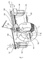
- the shape is a core 1 (rigid and removable) defining the geometry of the inner surface of the tire.
- This is coated with rubber 10 (see FIG. 2), for example a layer of butyl rubber-based sealing rubber, and a layer of rubber ensuring the anchoring of the carcass threads on the core during manufacturing, and then coating them in the vulcanized tire.
- the rubber 10 covering the core 1 allows to retain a wire 4 on the core 1 as it is removed, by a gluing effect.
- the core 1 is rotated by any suitable device, not shown.
- FIG 1 we see a single-arm animation mechanism 3 similar to that described in the patent application EP 1 231 049.
- a single arm 131 is seen mounted on a plate 130.
- This plate 130 constitutes a support carrying the animation mechanism, here constituted by the single arm 131.
- the plate 130 is slidably mounted on a rail 132.
- the plate 130 comprises a tab 134 which is a link 138 is articulated.
- the connecting rod 138 is also articulated to a crank 137 driven in rotation by a motor 136.
- the rotational movement of the motor does not reverse; the operating speed of the apparatus is of course proportional to the rotational speed of the motor 136.
- the motor 136 can rotate at constant speed (this is not required, however). This is symbolized in the drawing by an F1 arrow pointing to one side only.
- the plate 130 performs an alternative translation movement, guided by the rail 132. The amplitude of this movement depends on the size of the crank 137, which can be adjustable (not shown).
- the movement of the arm 131 is controlled by a motor 135 which drives a splined shaft 133.
- the splined shaft 133 passes through the plate 130.
- the rotational movement of the motor 135 is not continuous: the motor 135 is controlled so as to obtain an alternating movement of a predetermined amplitude, this movement being transmitted to the arm 131 via a simple internal movement return to the plate 130 (not shown).
- This type of movement alternative, is symbolized in the drawing by an arrow F2 pointing on both sides.
- this motion command by the expression "electric cam”.
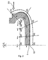
- the movement change direction but in addition its speed is continuously variable so as to obtain the successive positions of the characteristic points which will be explained with the aid of FIG. 2.
- the movements of the plate 130 and the arm 131 are synchronous.
- FIG. 2 The translational movement of the plate 130, combined with the movement of the arm 131 is illustrated in FIG. 2.
- the respective positions a1, a2, a3, a4 and a5 of the center of rotation of the arm 131 are seen.
- the single-arm animation mechanism it is a circle, see patent application EP 1 231 049
- the following overall movement is obtained: the curve in thick broken lines carrying the marks (1), (2 ), (3), (4) and (5) represents the movement of the end 16 of the laying arm 131, out of which the wire 4 is unwound.
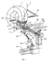
- the animation mechanism 3 is similar to what has already been described in the patent application EP 1 122 057.
- the dispensing member is an eyelet 6 mounted on an end arm 34.
- An arm main 31 is mounted on a plate 301 by means of a front auxiliary arm 32 and a rear auxiliary arm 33.
- the front auxiliary arm 32 is mounted on a shaft 320 and the rear auxiliary arm 33 is mounted on a shaft 330.
- the end arm 34 is inclined relative to the main arm 31 so as to bring the eyelet 6 of the bead of the future tire, even in the case where the form of manufacture is narrower at the height of the bead than mid-flank.
- the plate 301 is slidably mounted on two parallel bars 302.
- the plate 301 comprises a tab 3010 inside which is hollowed a light 3011.
- the plate 301 can perform an alternative translational movement, guided by the bars 302, thanks to a motor 361 controlling a lever 362.
- the rotation of the motor is not reversed, as shown in the drawing by an arrow F3 pointing to one side (which does not exclude a variable speed).
- a pin 363 which is engaged in the light 3011.
- the movement of the multi-arm animation mechanism 3 is controlled by a motor 351 which drives the shaft 320 via a telescopic shaft 353.
- the shaft 330 is driven by the shaft 320 via a cascade of gears disposed on the plate 301 and made so that the shaft 320 can oscillate at an amplitude for example of about 240 °.
- This type of movement is symbolized in the drawing by an arrow F4 pointing on both sides.
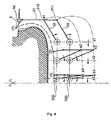
- FIG. 4 The translational movement of the plate 301, combined with the movement of the multi-arm animation mechanism 3 is illustrated in FIG. 4.
- the respective positions x1, x2 and x3 which are the trace of an imaginary plane connecting the axes are shown.
- the displacement of the plate 301 causes the displacement of the shafts 320 and 330, thus the displacement of the centers of rotation of the front auxiliary shafts 32 and rear 33.
- the curve in thick broken lines bearing the marks (1), (2) and (3) represents the movement of the eyecup 6 ;
- the curve in axial lines bearing the marks a1, a2 and a3 represents the movement in the space of the axis 310, that is to say also the movement in the space of the center of rotation 31R of the main arm 31;
- the curve bearing the marks b1, b2 and b3 represents the movement in the space of the stud 311.
- the whole arm animation mechanism 3, single arm or multiple arms, is quite compact.
- the assembly of the delivery members, namely the multi-arm animation mechanism 3, the control of the movement of the plate and the pressing devices 2, including the motor and the drive mechanism, form a subset which can easily be presented to the kernel appropriately, and can be retracted for example to present to the core of others devices used for the manufacture of a tire or for the evacuation of the core to other tire manufacturing stations.
Description
- La présente invention concerne la fabrication des pneumatiques. Plus précisément, elle se rapporte à la mise en place de fils pour constituer un renforcement du pneumatique. Plus particulièrement, elle propose des moyens aptes notamment à fabriquer un tel renforcement sur une forme proche ou identique de la forme de la cavité interne du pneumatique, c'est à dire une forme sensiblement toroïdale, supportant l'ébauche de pneumatique pendant sa fabrication.
- Dans ce domaine technique, on connaît déjà des procédés et appareils qui permettent d'intégrer la fabrication des renforcements de pneumatique à l'assemblage du pneumatique lui-même. Cela signifie que, plutôt que de recourir à des produits semi-finis, comme des nappes de renforcement, on réalise un ou des renforcements in situ, au moment où l'on fabrique le pneumatique, et à partir d'une bobine de fil. Parmi ces procédés et appareils, la solution décrite dans la demande de brevet EP 1 122 057 est bien adaptée pour la réalisation de renforcements de carcasse sur un noyau rigide dont la surface extérieure correspond sensiblement à la forme de la cavité interne du pneumatique final. On y voit un appareillage dans lequel le fil, destiné à constituer un renforcement de carcasse, est posé en arceaux contigus sur un noyau rigide, par un mécanisme présentant au moins deux bras arrangés en cascade, décrivant un mouvement de va-et-vient autour du noyau de façon à poser, progressivement et de façon contiguë, un arceau à chaque aller et un arceau à chaque retour, avec intervention de presseurs appropriés pour appliquer les extrémités desdits arceaux au fur et à mesure sur le noyau rigide. Le noyau a été revêtu préalablement de caoutchouc cru selon l'architecture du pneumatique à fabriquer, ce qui présente la propriété intéressante de permettre de coller suffisamment les arceaux et de les maintenir en place au moins pour les besoins de la fabrication.
- L'état de la technique connaît plusieurs autres appareils à bras unique ou multiples, décrivant des mouvements alternatifs pour transporter un oeilleton (ou un organe de dépose du fil similaire dans sa fonction) d'un côté à l'autre de la forme servant de support de fabrication pour un pneu. On peut citer les demandes de brevet EP 0 962 304, EP 1 231 049 et EP 1 231 050.
- Si l'on souhaite construire un appareil apte à fabriquer des pneus de très grande largeur, on peut être conduit à un encombrement conséquent dans la dimension radiale par rapport à la forme de fabrication, notamment un encombrement qui peut devenir considérablement plus important que pour un appareil à chaîne comme décrit dans la demande de brevet EP 0 580 055.
- L'objectif de la présente invention est d'augmenter la capacité des appareils réalisés sur le principe d'un ou de plusieurs bras décrivant un mouvement alternatif à fabriquer des pneus de grande largeur, sans trop alourdir lesdits appareils et en les rendant aussi compacts que possible.
- L'invention propose un appareil de fabrication d'un renforcement pour pneumatique, ledit appareil étant destiné à fabriquer un renforcement constitué à partir d'un fil, ledit appareil comprenant un bâti et étant destiné à être utilisé en coopération avec une forme sensiblement toroïdale, montée sur le bâti de façon rotative autour d'un axe de rotation, sur laquelle on construit progressivement ledit renforcement en déposant des arceaux dudit fil selon une trajectoire souhaitée pour ledit fil à la surface de ladite forme, ledit appareil comprenant :
- un organe de dépose du fil dans lequel le fil peut coulisser,
- un mécanisme d'animation comportant au moins un bras sur lequel est monté, directement ou indirectement, ledit organe de dépose, le mécanisme d'animation étant agencé pour transporter ledit organe de dépose selon un mouvement cyclique, en va-et-vient, l'amenant en cycles successifs au voisinage de chacune des extrémités souhaitées pour le fil dans ladite trajectoire,
- des presseurs proches de chaque extrémité de ladite trajectoire, pour appliquer le fil sur la forme au moins auxdites extrémités,
- le mécanisme d'animation est monté sur le bâti par l'intermédiaire d'un support qui lui-même est monté sur des moyens procurant un degré de liberté par rapport au bâti permettant un mouvement compris dans un plan parallèle à l'axe de rotation de la forme.
- L'intérêt de cette conception est de conférer au mécanisme d'animation un degré de liberté de mouvement supplémentaire par la translation transversale fonctionnelle d'un support sur lequel il est monté, et d'augmenter en cela la capacité de pose en largeur parallèlement à l'axe de rotation de la forme de fabrication, sans augmentation substantielle de la dimension dans le sens radial dudit appareil.
- L'invention peut être utilisée avec de nombreux mécanismes de pose d'un fil de renforcement, notamment parmi les mécanismes connus tous ceux à bras alternatif(s) décrits dans les demandes de brevet précitées, ou encore celui décrit dans la demande de brevet déposée le même jour par les mêmes déposants et ayant pour titre : « appareil de fabrication d'un renforcement pour pneumatique, à bras de pose multiples comportant un mouvement guidé par un suiveur de came coulissant dans une lumière ».
- Deux exemples d'applications sont donnés ci-dessous : un exemple où le mécanisme d'animation ne comporte qu'un seul bras oscillant à l'extrémité duquel est directement monté l'organe de dépose. Le second exemple montre un mécanisme d'animation comportant des bras multiples oscillants : le mécanisme d'animation comporte un bras principal monté à l'extrémité de deux bras auxiliaires, l'organe de dépose est monté directement à l'extrémité du bras principal. Bien entendu, ces exemples ne sont pas limitatifs. Dans tous ces exemples, étant donné qu'il s'agit chaque fois de fabriquer un pneumatique à carcasse radiale, lesdits moyens procurant au support un degré de liberté organisent un mouvement parallèle à l'axe de rotation de la forme, sans que ceci soit limitatif.
- Le lecteur est invité à consulter plus en détails notamment par exemple la demande de brevet EP 1 122 057 car le procédé de fabrication d'un pneu mis en oeuvre dans la présente demande est identique à celui de ladite demande. L'appareil est destiné à être utilisé avec un système de motorisation commandant en synchronisme la rotation de la forme, le mécanisme d'animation et les presseurs. En outre, la présente invention utilise les presseurs décrits dans la demande de brevet EP 1 122 057 (ensemble comportant un marteau et une fourche), pour permettre la formation d'une boucle avec le fil de renforcement et pour appliquer ladite boucle contre le noyau.
- Avant d'aborder en détails la description des nouveaux moyens d'animation de l'organe de dépose du fil, rappelons quelques points utiles.
- Notons tout d'abord que, comme dans la demande de brevet EP 1 122 057 déjà citée, le terme "fil" doit bien entendu être compris dans un sens tout à fait général, englobant un monofilament, un multifilament, un assemblage comme par exemple un câble ou un retors, ou un petit nombre de câbles ou retors groupés, et ceci quelle que soit la nature du matériau, et que le "fil" soit pré revêtu de caoutchouc ou non. Dans le présent mémoire, on emploie le terme "arceau" pour désigner un tronçon de fil allant d'un point singulier à un autre dans le renforcement. L'ensemble de ces arceaux disposés sur tout le pourtour du pneumatique forme le renforcement proprement dit. Un arceau au sens défini ici peut faire partie d'une carcasse, ou d'un renfort de sommet, ou de tout autre type de renfort. Ces arceaux peuvent être individualisés par une coupe du fil en cours de pose, ou tous reliés entre eux dans le renforcement final, par exemple par des boucles.
- Fondamentalement, l'invention traite de la dépose en continu d'un fil de renforcement, dans une configuration aussi proche que possible de la configuration dans le produit final. Le fil est délivré à la demande par un distributeur approprié comportant par exemple une bobine de fil et le cas échéant un dispositif de contrôle de la tension du fil extrait de la bobine. L'appareil de fabrication d'un renfort à partir d'un seul fil coopère avec une forme (noyau rigide ou une membrane armée) sur laquelle on fabrique le pneumatique. Il importe peu que le renforcement soit fabriqué en plusieurs rotations successives de la forme par devant les organes de pose décrits, avec coupe du fil ou non entre deux rotations successives.
- Lorsque l'on définit des positions, des directions ou des sens avec les mots "radialement, axialement, circonférentiellement", ou lorsque l'on parle de rayons, on prend pour repère le noyau sur lequel on fabrique le pneumatique, ou le pneumatique par lui-même, ce qui revient au même. L'axe géométrique de référence est l'axe de rotation de la forme.
- Eu outre, les organes de pose du fil décrits ici permettent aussi de réaliser un renforcement, par exemple un renforcement de carcasse, dans lequel le pas de pose du fil est variable. On entend par "pas de pose" la distance résultant de la somme de l'écart entre deux fils adjacents et le diamètre du fil. Il est bien connu que pour un renforcement de carcasse, l'écart entre fils varie selon le rayon auquel on le mesure. Il ne s'agit pas de cette variation dont il est question ici, mais bien d'un pas variable à un rayon donné. Il suffit pour cela de, sans changer la cadence de travail de l'organe de dépose, faire varier selon toute loi appropriée la vitesse de rotation de la forme. On obtient ainsi un pneumatique dont les fils de renforcement de carcasse, par exemple pour une carcasse radiale, sont disposés selon un pas présentant une variation contrôlée pour une position radiale donnée.
- Enfin, le bras ou les bras multiples font décrire à l'organe de dépose du fil un mouvement sensiblement compris dans un plan -appelé dans la suite le plan de mouvement- perpendiculaire à l'axe géométrique de rotation du ou des bras. Dans certaines mises en oeuvre particulières de l'invention, tout comme dans la demande de brevet EP 1 122 057 précitée, ledit plan de mouvement est lui-même animé d'un mouvement ayant un rôle fonctionnel comme cela apparaîtra ci-dessous.
- La suite de la description permet de bien faire comprendre tous les aspects de l'invention, en s'appuyant sur les figures suivantes :
- La figure 1 est une perspective schématique montrant un premier mode de réalisation d'un appareil selon l'invention ;
- La figure 2 représente les stades successifs du fonctionnement du premier mode de réalisation ;
- La figure 3 est une perspective schématique montrant un deuxième mode de réalisation d'un appareil selon l'invention ;
- La figure 4 représente les stades successifs du fonctionnement du deuxième mode de réalisation.
- A la figure 1 (ainsi que d'ailleurs pour tous les exemples décrits, sans toutefois que ceci soit limitatif), la forme est un noyau 1 (rigide et démontable) définissant la géométrie de la surface intérieure du pneumatique. Celui-ci est revêtu de caoutchouc 10 (voir figure 2), par exemple d'une couche de gomme d'étanchéité à base de caoutchouc butyl, et d'une couche de gomme assurant l'ancrage des fils de carcasse sur le noyau pendant la fabrication, puis l'enrobage de ceux-ci dans le pneu vulcanisé. Le caoutchouc 10 recouvrant le noyau 1 permet de retenir un fil 4 sur le noyau 1 au fur et à mesure de sa dépose, par un effet de collage. Bien entendu, le noyau 1 est entraîné en rotation par tout dispositif convenable, non représenté.
- A la figure 1, on voit un mécanisme d'animation 3 à bras unique ressemblant à ce qui est décrit dans la demande de brevet EP 1 231 049. On voit un bras 131 unique monté sur une platine 130. Cette platine 130 constitue un support portant le mécanisme d'animation, ici constitué par le bras unique 131. La platine 130 est montée coulissante sur un rail 132. La platine 130 comporte une patte 134 à laquelle est une bielle 138 est articulée. La bielle 138 est par ailleurs articulée à une manivelle 137 entraînée en rotation par un moteur 136. Le mouvement de rotation du moteur ne s'inverse pas ; la cadence de fonctionnement de l'appareil est bien entendu proportionnelle à la vitesse de rotation du moteur 136. Pour faire fonctionner l'appareil à cadence constante, c'est à dire à un nombre d'arceaux de fil déposés par unité de temps constant, le moteur 136 peut tourner à régime constant (ce n'est cependant pas obligatoire). Cela est symbolisé au dessin par une flèche F1 pointant d'un seul côté. La platine 130 effectue un mouvement de translation alternative, guidé par le rail 132. L'amplitude de ce mouvement dépend de la dimension de la manivelle 137, laquelle peut être réglable (non représenté).
- Le mouvement du bras 131 est commandé par un moteur 135 qui entraîne un arbre cannelé 133. L'arbre cannelé 133 traverse la platine 130. Le mouvement de rotation du moteur 135 n'est pas continu : le moteur 135 est commandé de façon à obtenir un mouvement alternatif d'une amplitude prédéterminée, ce mouvement étant transmis au bras 131 par l'intermédiaire d'un simple renvoi de mouvement interne à la platine 130 (non représenté). Ce type de mouvement, alternatif, est symbolisé au dessin par une flèche F2 pointant des deux côtés. Convenons d'appeler cette commande de mouvement par l'expression « came électrique ». De préférence, non seulement ce mouvement change de sens, mais en outre sa vitesse est continûment variable de façon à obtenir les positions successives des points caractéristiques qui vont être expliquées à l'aide de la figure 2. Bien entendu, les mouvements de la platine 130 et du bras 131 sont synchrones.
- Le mouvement de translation de la platine 130, combiné au mouvement du bras 131 est illustré à la figure 2. On voit les positions respectives a1, a2, a3, a4 et a5 possibles du centre de rotation du bras 131. En superposant ce déplacement transversal au mouvement propre du mécanisme d'animation à bras unique (c'est un cercle, voir demande de brevet EP 1 231 049), on obtient le mouvement global suivant : la courbe en traits interrompus épais portant les repères (1), (2), (3), (4) et (5) représente le mouvement de l'extrémité 16 du bras 131 de pose, hors de laquelle le fil 4 est dévidé.
- En variante, on aurait pu commander le mouvement de la platine 130 par une came électrique. On pourrait aussi commander les deux mouvements (celui du bras 131 et celui de la platine 130) chacun par une came électrique. En variante encore, on aurait pu commander l'un ou l'autre des mouvements du bras 131 ou de la platine 130, ou les deux, par un système à came mécanique, dessinée pour obtenir les positions successives préférées décrites à la figure 2.
- A la figure 3, le mécanisme d'animation 3 est similaire à ce qui a déjà été décrit dans la demande de brevet EP 1 122 057. L'organe de dépose est un oeilleton 6 monté sur un bras d'extrémité 34. Un bras principal 31 est monté sur une platine 301 au moyen d'un bras auxiliaire avant 32 et d'un bras auxiliaire arrière 33. Le bras auxiliaire avant 32 est monté sur un arbre 320 et le bras auxiliaire arrière 33 est monté sur un arbre 330. Le bras d'extrémité 34 s'incline par rapport au bras principal 31 de façon à rapprocher l'oeilleton 6 du bourrelet du futur pneumatique, même dans le cas où la forme de fabrication est plus étroite à hauteur du bourrelet que à mi flanc. Le choix du degré d'inclinaison, c'est à dire de rapprochement du la zone du futur bourrelet, est obtenu par une commande judicieuse dont le lecteur trouvera tous les détails dans la demande de brevet EP 1 122 057 (non représentée ici pour ne pas surcharger le dessin). Lesdits bras n'effectuent pas de rotation continue, mais oscillent dans les limites d'un arc inférieur à 360°, la valeur précise dépendant de la constitution exacte du mécanisme d'animation à bras multiples 3 et de l'application visée.
- La platine 301 est montée coulissante sur deux barreaux parallèles 302. La platine 301 comporte une patte 3010 à l'intérieur de laquelle est creusée une lumière 3011. La platine 301 peut effectuer un mouvement de translation alternative, guidé par les barreaux 302, grâce à un moteur 361 commandant un levier 362. La rotation du moteur ne s'inverse pas, comme symbolisé au dessin par une flèche F3 pointant d'un seul côté (ce qui n'exclut pas une vitesse variable). A l'extrémité du levier 362 est installé un téton 363 qui est engagé dans la lumière 3011.
- Le mouvement du mécanisme d'animation 3 à bras multiples est commandé par un moteur 351 qui entraîne l'arbre 320 par l'intermédiaire d'un arbre télescopique 353. L'arbre 330 est entraîné par l'arbre 320 via une cascade d'engrenages disposée sur la platine 301 et réalisée de telle sorte que l'arbre 320 peut osciller selon une amplitude par exemple d'environ 240°. Ce type de mouvement, alternatif, est symbolisé au dessin par une flèche F4 pointant des deux côtés. Dans ce mode de réalisation comme dans le précédent, on peut adopter de nombreuses variantes pour la commande des mouvements, en utilisant des cames mécaniques, ou des cames électriques.
- Le mouvement de translation de la platine 301, combiné au mouvement du mécanisme d'animation 3 à bras multiples est illustré à la figure 4. On voit les positions respectives x1, x2 et x3 qui sont la trace d'un plan imaginaire reliant les axes géométriques des arbres 320 et 330. Le déplacement de la platine 301 provoque le déplacement des arbres 320 et 330, donc le déplacement des centres de rotation des arbres auxiliaires avant 32 et arrière 33. En superposant ce déplacement transversal au mouvement propre du mécanisme d'animation 3 à bras multiples expliqué à l'aide de la figure 2, on obtient les mouvements globaux suivants : la courbe en traits interrompus épais portant les repères (1), (2) et (3) représente le mouvement de l'oeilleton 6 ; la courbe en traits d'axe portant les repères a1, a2 et a3 représente le mouvement dans l'espace de l'axe 310, c'est-à-dire aussi le mouvement dans l'espace du centre de rotation 31R du bras principal 31 ; enfin, la courbe portant les repères b1, b2 et b3 représente le mouvement dans l'espace du téton 311.
- L'ensemble du mécanisme d'animation à bras 3, bras unique ou bras multiples, est assez compact. L'ensemble des organes de pose, à savoir le mécanisme d'animation à bras multiples 3, la commande du mouvement de la platine et les dispositifs presseurs 2, y compris le moteur et le mécanisme d'entraînement, forment un sous-ensemble pouvant facilement être présenté au noyau de façon appropriée, et pouvant être escamoté pour par exemple présenter au noyau d'autres dispositifs utilisés pour la fabrication d'un pneumatique ou pour l'évacuation du noyau vers d'autres postes de confection d'un pneumatique.
Claims (8)
- Appareil de fabrication d'un renforcement pour pneumatique, ledit appareil étant destiné à fabriquer un renforcement constitué à partir d'un fil (4), ledit appareil comprenant un bâti et étant destiné à être utilisé en coopération avec une forme (1) sensiblement toroïdale, montée sur le bâti de façon rotative autour d'un axe de rotation, sur laquelle on construit progressivement ledit renforcement en déposant des arceaux dudit fil selon une trajectoire souhaitée pour ledit fil à la surface de ladite forme, ledit appareil comprenant :• un organe de dépose du fil dans lequel le fil peut coulisser,• un mécanisme d'animation comportant au moins un bras (131) sur lequel est monté, directement ou indirectement, ledit organe de dépose, le mécanisme d'animation étant agencé pour transporter ledit organe de dépose selon un mouvement cyclique, en va-et-vient, l'amenant en cycles successifs au voisinage de chacune des extrémités souhaitées pour le fil dans ladite trajectoire,• des presseurs (2G et 2D) proches de chaque extrémité de ladite trajectoire, pour appliquer le fil sur la forme au moins auxdites extrémités,caractérisé en ce que• le mécanisme d'animation est monté sur le bâti par l'intermédiaire d'un support qui lui-même est monté sur des moyens (132, 136, 137, 138) procurant un degré de liberté par rapport au bâti permettant un mouvement compris dans un plan parallèle à l'axe de rotation de la forme.
- Appareil selon la revendication 1, dans lequel lesdits moyens (132) procurant au support un degré de liberté organisent un mouvement parallèle à l'axe de rotation de la forme
- Appareil selon la revendication 1, dans lequel le mécanisme d'animation comporte un seul bras oscillant (131) à l'extrémité duquel est monté ledit organe de dépose.
- Appareil selon la revendication 1, dans lequel le mécanisme d'animation comporte des bras multiples (31, 32, 33, 34).
- Appareil selon la revendication 3 dans lequel le mécanisme d'animation comporte un bras principal monté à l'extrémité de bras auxiliaires.
- Appareil selon la revendication 4 dans lequel ledit organe de dépose est monté directement à l'extrémité du bras principal.
- Appareil selon l'une des revendications 1 à 5, dans lequel l'organe de dépose est un oeilleton (6).
- Appareil selon l'une des revendications 1 à 6, utilisé avec un système de motorisation commandant en synchronisme la rotation de la forme, le mécanisme d'animation et les presseurs, dans lequel le système de motorisation commande en synchronisme le mouvement dudit support.
Applications Claiming Priority (2)
| Application Number | Priority Date | Filing Date | Title |
|---|---|---|---|
| FR0215306 | 2002-12-04 | ||
| FR0215306 | 2002-12-04 |
Publications (3)
| Publication Number | Publication Date |
|---|---|
| EP1426169A2 EP1426169A2 (fr) | 2004-06-09 |
| EP1426169A3 EP1426169A3 (fr) | 2004-12-22 |
| EP1426169B1 true EP1426169B1 (fr) | 2006-09-20 |
Family
ID=32310002
Family Applications (1)
| Application Number | Title | Priority Date | Filing Date |
|---|---|---|---|
| EP03026367A Expired - Lifetime EP1426169B1 (fr) | 2002-12-04 | 2003-11-18 | Appareil de fabrication d'un renforcement pour pneumatiques de grande largeur |
Country Status (6)
| Country | Link |
|---|---|
| US (1) | US7128116B2 (fr) |
| EP (1) | EP1426169B1 (fr) |
| JP (1) | JP2004181962A (fr) |
| AT (1) | ATE340070T1 (fr) |
| DE (1) | DE60308467T2 (fr) |
| ES (1) | ES2268257T3 (fr) |
Families Citing this family (5)
| Publication number | Priority date | Publication date | Assignee | Title |
|---|---|---|---|---|
| US20040154727A1 (en) * | 2003-02-11 | 2004-08-12 | Weissert James Thomas | Method and apparatus for manufacturing carcass plies for a tire |
| US7736454B2 (en) | 2004-02-12 | 2010-06-15 | The Goodyear Tire & Rubber Company | Method for incorporating an annular antenna and electronics into a tire |
| FR2909108B1 (fr) * | 2006-11-24 | 2009-07-10 | Michelin Soc Tech | Fil gaine pour la fabrication d'un pneumatique, pneumatique muni de ce fil gaine, dispositif pour la fabrication de ce fil gaine, installation et procede pour la fabrication de ce pneumantique. |
| US20080314524A1 (en) * | 2007-06-20 | 2008-12-25 | Andres Ignacio Delgado | Method for single line tire ply construction |
| US20080314216A1 (en) * | 2007-06-20 | 2008-12-25 | Andres Ignacio Delgado | Tire cord cutting apparatus |
Family Cites Families (7)
| Publication number | Priority date | Publication date | Assignee | Title |
|---|---|---|---|---|
| DE1131000B (de) * | 1957-08-05 | 1962-06-07 | Pirelli | Verfahren und Vorrichtung zur Herstellung ringfoermiger Baender aus mindestens einem durchgehenden Faden auf einer Trommel mit einziehbarem Kranz, insbesondere zur Herstellung von Verstaerkungslagen fuer Kraftfahrzeug-luftreifen |
| US4830781A (en) * | 1987-09-18 | 1989-05-16 | The Armstrong Rubber Company | Tire body reinforcing component and apparatus and method for producing same |
| FR2804367B1 (fr) * | 2000-02-01 | 2002-09-20 | Sedepro | Appareil a bras oscillant, pour la fabrication d'un renfort de pneumatique a partir d'un seul fil |
| JP4315548B2 (ja) * | 1999-11-19 | 2009-08-19 | 株式会社ブリヂストン | タイヤカーカスの形成装置および形成方法 |
| FR2804368A1 (fr) * | 2000-02-01 | 2001-08-03 | Sedepro | Appareil pour la fabrication de renforts pour pneumatique |
| DE60218771T2 (de) * | 2001-02-07 | 2007-12-13 | Société de Technologie Michelin | Schwingarmvorrichtung zur Herstellung einer Reifenverstärkungsstruktur mit einem einzigen Reifenkord |
| DE60221580T2 (de) * | 2001-02-07 | 2008-04-17 | Société de Technologie Michelin | Schwingarmvorrichtung zur Herstellung einer Reifenverstärkungsstruktur mit einem einzigen Reifenkord |
-
2003
- 2003-11-18 ES ES03026367T patent/ES2268257T3/es not_active Expired - Lifetime
- 2003-11-18 DE DE60308467T patent/DE60308467T2/de not_active Expired - Fee Related
- 2003-11-18 AT AT03026367T patent/ATE340070T1/de not_active IP Right Cessation
- 2003-11-18 EP EP03026367A patent/EP1426169B1/fr not_active Expired - Lifetime
- 2003-12-01 JP JP2003401412A patent/JP2004181962A/ja not_active Abandoned
- 2003-12-01 US US10/725,761 patent/US7128116B2/en not_active Expired - Fee Related
Also Published As
| Publication number | Publication date |
|---|---|
| JP2004181962A (ja) | 2004-07-02 |
| US7128116B2 (en) | 2006-10-31 |
| DE60308467T2 (de) | 2007-09-13 |
| EP1426169A2 (fr) | 2004-06-09 |
| ATE340070T1 (de) | 2006-10-15 |
| DE60308467D1 (de) | 2006-11-02 |
| ES2268257T3 (es) | 2007-03-16 |
| EP1426169A3 (fr) | 2004-12-22 |
| US20040108072A1 (en) | 2004-06-10 |
Similar Documents
| Publication | Publication Date | Title |
|---|---|---|
| EP1464472B1 (fr) | Appareil à bras oscillant, pour la fabrication d'un renfort de pneumatique à partir d'un seul fil | |
| EP0580055B1 (fr) | Procédé et machine pour la mise en place sur noyau d'un seul fil de renfort dans la fabrication d'une carcasse de pneumatique | |
| EP0248301B1 (fr) | Procédé et machine de fabrication d'un renforcement pour pneumatique | |
| EP1537985B1 (fr) | Appareil à bras oscillant, pour la fabrication d'un renfort de pneumatique à partir d'un seul fil | |
| EP0582215B1 (fr) | Procédé de fabrication d'un pneumatique et machine de fabrication d'un renfort de sommet pour pneumatique | |
| EP1231049B1 (fr) | Appareil a bras oscillant unique, pour la fabrication d'un renfort de pneumatique a partir d'un seul fil | |
| EP1517781B1 (fr) | Appareil de fabrication d une structure de renforcement pour pneumatique, comprenant un mecanisme de retournement de la bandelette | |
| EP1122055B1 (fr) | Appareil à combination de mouvements, pour la fabrication d'un renfort de pneumatique à partir d'un seul fil | |
| EP0519294A1 (fr) | Procédé de fabrication d'un pneumatique et machines pour la mise en oeuvre de ce procédé | |
| EP1426169B1 (fr) | Appareil de fabrication d'un renforcement pour pneumatiques de grande largeur | |
| EP1711335B1 (fr) | Procede et dispositif pour la fabrication d'un renforcement pour pneumatique | |
| EP1426170B1 (fr) | Appareil de fabrication d'un renforcement pour pneumatique, à bras de pose multiples | |
| EP1147864A2 (fr) | Dispositif de coupe à grande vitesse pour couper un renfort de pneumatique | |
| EP1513672B1 (fr) | Fabrication d'une structure de renforcement pour pneumatique avec controle volumetrique de la matrice | |
| EP1590169B1 (fr) | Appareil de fabrication d'un renforcement pour pneumatique, comportant un dispositif pour le guidage du fil de renforcement, et procede de fabrication d'un tel renforcement au moyen de cet appareil. | |
| EP1279484B1 (fr) | Appareil et procédé de fabrication d'un renforcement pour pnumatique | |
| EP0353511B1 (fr) | Eléments constitutifs d'un appareil de fabrication d'un renforcement pour pneumatique | |
| EP1824666B1 (fr) | Appareil de fabrication d'un renforcement pour pneumatique | |
| EP0704295A1 (fr) | Renforcement d'une matrice en matériau caoutchouteux par des fils |
Legal Events
| Date | Code | Title | Description |
|---|---|---|---|
| PUAI | Public reference made under article 153(3) epc to a published international application that has entered the european phase |
Free format text: ORIGINAL CODE: 0009012 |
|
| AK | Designated contracting states |
Kind code of ref document: A2 Designated state(s): AT BE BG CH CY CZ DE DK EE ES FI FR GB GR HU IE IT LI LU MC NL PT RO SE SI SK TR |
|
| AX | Request for extension of the european patent |
Extension state: AL LT LV MK |
|
| PUAL | Search report despatched |
Free format text: ORIGINAL CODE: 0009013 |
|
| AK | Designated contracting states |
Kind code of ref document: A3 Designated state(s): AT BE BG CH CY CZ DE DK EE ES FI FR GB GR HU IE IT LI LU MC NL PT RO SE SI SK TR |
|
| AX | Request for extension of the european patent |
Extension state: AL LT LV MK |
|
| 17P | Request for examination filed |
Effective date: 20050622 |
|
| AKX | Designation fees paid |
Designated state(s): AT BE BG CH CY CZ DE DK EE ES FI FR GB GR HU IE IT LI LU MC NL PT RO SE SI SK TR |
|
| GRAP | Despatch of communication of intention to grant a patent |
Free format text: ORIGINAL CODE: EPIDOSNIGR1 |
|
| GRAS | Grant fee paid |
Free format text: ORIGINAL CODE: EPIDOSNIGR3 |
|
| GRAA | (expected) grant |
Free format text: ORIGINAL CODE: 0009210 |
|
| AK | Designated contracting states |
Kind code of ref document: B1 Designated state(s): AT BE BG CH CY CZ DE DK EE ES FI FR GB GR HU IE IT LI LU MC NL PT RO SE SI SK TR |
|
| PG25 | Lapsed in a contracting state [announced via postgrant information from national office to epo] |
Ref country code: IT Free format text: LAPSE BECAUSE OF FAILURE TO SUBMIT A TRANSLATION OF THE DESCRIPTION OR TO PAY THE FEE WITHIN THE PRESCRIBED TIME-LIMIT;WARNING: LAPSES OF ITALIAN PATENTS WITH EFFECTIVE DATE BEFORE 2007 MAY HAVE OCCURRED AT ANY TIME BEFORE 2007. THE CORRECT EFFECTIVE DATE MAY BE DIFFERENT FROM THE ONE RECORDED. Effective date: 20060920 Ref country code: SK Free format text: LAPSE BECAUSE OF FAILURE TO SUBMIT A TRANSLATION OF THE DESCRIPTION OR TO PAY THE FEE WITHIN THE PRESCRIBED TIME-LIMIT Effective date: 20060920 Ref country code: CZ Free format text: LAPSE BECAUSE OF FAILURE TO SUBMIT A TRANSLATION OF THE DESCRIPTION OR TO PAY THE FEE WITHIN THE PRESCRIBED TIME-LIMIT Effective date: 20060920 Ref country code: RO Free format text: LAPSE BECAUSE OF FAILURE TO SUBMIT A TRANSLATION OF THE DESCRIPTION OR TO PAY THE FEE WITHIN THE PRESCRIBED TIME-LIMIT Effective date: 20060920 Ref country code: SI Free format text: LAPSE BECAUSE OF FAILURE TO SUBMIT A TRANSLATION OF THE DESCRIPTION OR TO PAY THE FEE WITHIN THE PRESCRIBED TIME-LIMIT Effective date: 20060920 Ref country code: AT Free format text: LAPSE BECAUSE OF FAILURE TO SUBMIT A TRANSLATION OF THE DESCRIPTION OR TO PAY THE FEE WITHIN THE PRESCRIBED TIME-LIMIT Effective date: 20060920 Ref country code: IE Free format text: LAPSE BECAUSE OF FAILURE TO SUBMIT A TRANSLATION OF THE DESCRIPTION OR TO PAY THE FEE WITHIN THE PRESCRIBED TIME-LIMIT Effective date: 20060920 Ref country code: FI Free format text: LAPSE BECAUSE OF FAILURE TO SUBMIT A TRANSLATION OF THE DESCRIPTION OR TO PAY THE FEE WITHIN THE PRESCRIBED TIME-LIMIT Effective date: 20060920 |
|
| REG | Reference to a national code |
Ref country code: GB Ref legal event code: FG4D Free format text: NOT ENGLISH |
|
| REG | Reference to a national code |
Ref country code: CH Ref legal event code: EP |
|
| REG | Reference to a national code |
Ref country code: IE Ref legal event code: FG4D Free format text: LANGUAGE OF EP DOCUMENT: FRENCH |
|
| REF | Corresponds to: |
Ref document number: 60308467 Country of ref document: DE Date of ref document: 20061102 Kind code of ref document: P |
|
| GBT | Gb: translation of ep patent filed (gb section 77(6)(a)/1977) |
Effective date: 20061101 |
|
| PG25 | Lapsed in a contracting state [announced via postgrant information from national office to epo] |
Ref country code: BE Free format text: LAPSE BECAUSE OF NON-PAYMENT OF DUE FEES Effective date: 20061130 Ref country code: MC Free format text: LAPSE BECAUSE OF NON-PAYMENT OF DUE FEES Effective date: 20061130 |
|
| PG25 | Lapsed in a contracting state [announced via postgrant information from national office to epo] |
Ref country code: SE Free format text: LAPSE BECAUSE OF FAILURE TO SUBMIT A TRANSLATION OF THE DESCRIPTION OR TO PAY THE FEE WITHIN THE PRESCRIBED TIME-LIMIT Effective date: 20061220 Ref country code: DK Free format text: LAPSE BECAUSE OF FAILURE TO SUBMIT A TRANSLATION OF THE DESCRIPTION OR TO PAY THE FEE WITHIN THE PRESCRIBED TIME-LIMIT Effective date: 20061220 Ref country code: BG Free format text: LAPSE BECAUSE OF FAILURE TO SUBMIT A TRANSLATION OF THE DESCRIPTION OR TO PAY THE FEE WITHIN THE PRESCRIBED TIME-LIMIT Effective date: 20061220 |
|
| PG25 | Lapsed in a contracting state [announced via postgrant information from national office to epo] |
Ref country code: PT Free format text: LAPSE BECAUSE OF FAILURE TO SUBMIT A TRANSLATION OF THE DESCRIPTION OR TO PAY THE FEE WITHIN THE PRESCRIBED TIME-LIMIT Effective date: 20070312 |
|
| REG | Reference to a national code |
Ref country code: ES Ref legal event code: FG2A Ref document number: 2268257 Country of ref document: ES Kind code of ref document: T3 |
|
| REG | Reference to a national code |
Ref country code: IE Ref legal event code: FD4D |
|
| PLBE | No opposition filed within time limit |
Free format text: ORIGINAL CODE: 0009261 |
|
| STAA | Information on the status of an ep patent application or granted ep patent |
Free format text: STATUS: NO OPPOSITION FILED WITHIN TIME LIMIT |
|
| 26N | No opposition filed |
Effective date: 20070621 |
|
| BERE | Be: lapsed |
Owner name: MICHELIN RECHERCHE ET TECHNIQUE S.A. Effective date: 20061130 Owner name: SOC. DE TECHNOLOGIE MICHELIN Effective date: 20061130 |
|
| PG25 | Lapsed in a contracting state [announced via postgrant information from national office to epo] |
Ref country code: GR Free format text: LAPSE BECAUSE OF FAILURE TO SUBMIT A TRANSLATION OF THE DESCRIPTION OR TO PAY THE FEE WITHIN THE PRESCRIBED TIME-LIMIT Effective date: 20061221 |
|
| PG25 | Lapsed in a contracting state [announced via postgrant information from national office to epo] |
Ref country code: EE Free format text: LAPSE BECAUSE OF FAILURE TO SUBMIT A TRANSLATION OF THE DESCRIPTION OR TO PAY THE FEE WITHIN THE PRESCRIBED TIME-LIMIT Effective date: 20060920 |
|
| PG25 | Lapsed in a contracting state [announced via postgrant information from national office to epo] |
Ref country code: CH Free format text: LAPSE BECAUSE OF NON-PAYMENT OF DUE FEES Effective date: 20071130 Ref country code: LI Free format text: LAPSE BECAUSE OF NON-PAYMENT OF DUE FEES Effective date: 20071130 Ref country code: HU Free format text: LAPSE BECAUSE OF FAILURE TO SUBMIT A TRANSLATION OF THE DESCRIPTION OR TO PAY THE FEE WITHIN THE PRESCRIBED TIME-LIMIT Effective date: 20070321 Ref country code: TR Free format text: LAPSE BECAUSE OF FAILURE TO SUBMIT A TRANSLATION OF THE DESCRIPTION OR TO PAY THE FEE WITHIN THE PRESCRIBED TIME-LIMIT Effective date: 20060920 |
|
| REG | Reference to a national code |
Ref country code: CH Ref legal event code: PL |
|
| PG25 | Lapsed in a contracting state [announced via postgrant information from national office to epo] |
Ref country code: CY Free format text: LAPSE BECAUSE OF FAILURE TO SUBMIT A TRANSLATION OF THE DESCRIPTION OR TO PAY THE FEE WITHIN THE PRESCRIBED TIME-LIMIT Effective date: 20060920 |
|
| PGFP | Annual fee paid to national office [announced via postgrant information from national office to epo] |
Ref country code: DE Payment date: 20081121 Year of fee payment: 6 Ref country code: LU Payment date: 20081127 Year of fee payment: 6 Ref country code: NL Payment date: 20081113 Year of fee payment: 6 |
|
| PGFP | Annual fee paid to national office [announced via postgrant information from national office to epo] |
Ref country code: ES Payment date: 20081121 Year of fee payment: 6 |
|
| PGFP | Annual fee paid to national office [announced via postgrant information from national office to epo] |
Ref country code: IT Payment date: 20081120 Year of fee payment: 6 |
|
| PGFP | Annual fee paid to national office [announced via postgrant information from national office to epo] |
Ref country code: FR Payment date: 20081113 Year of fee payment: 6 |
|
| PGFP | Annual fee paid to national office [announced via postgrant information from national office to epo] |
Ref country code: GB Payment date: 20081117 Year of fee payment: 6 |
|
| REG | Reference to a national code |
Ref country code: NL Ref legal event code: V1 Effective date: 20100601 |
|
| GBPC | Gb: european patent ceased through non-payment of renewal fee |
Effective date: 20091118 |
|
| REG | Reference to a national code |
Ref country code: FR Ref legal event code: ST Effective date: 20100730 |
|
| PG25 | Lapsed in a contracting state [announced via postgrant information from national office to epo] |
Ref country code: NL Free format text: LAPSE BECAUSE OF NON-PAYMENT OF DUE FEES Effective date: 20100601 Ref country code: FR Free format text: LAPSE BECAUSE OF NON-PAYMENT OF DUE FEES Effective date: 20091130 |
|
| PG25 | Lapsed in a contracting state [announced via postgrant information from national office to epo] |
Ref country code: DE Free format text: LAPSE BECAUSE OF NON-PAYMENT OF DUE FEES Effective date: 20100601 |
|
| PG25 | Lapsed in a contracting state [announced via postgrant information from national office to epo] |
Ref country code: GB Free format text: LAPSE BECAUSE OF NON-PAYMENT OF DUE FEES Effective date: 20091118 |
|
| REG | Reference to a national code |
Ref country code: ES Ref legal event code: FD2A Effective date: 20110325 |
|
| PG25 | Lapsed in a contracting state [announced via postgrant information from national office to epo] |
Ref country code: IT Free format text: LAPSE BECAUSE OF NON-PAYMENT OF DUE FEES Effective date: 20091118 |
|
| PG25 | Lapsed in a contracting state [announced via postgrant information from national office to epo] |
Ref country code: LU Free format text: LAPSE BECAUSE OF NON-PAYMENT OF DUE FEES Effective date: 20091118 |
|
| PG25 | Lapsed in a contracting state [announced via postgrant information from national office to epo] |
Ref country code: ES Free format text: LAPSE BECAUSE OF NON-PAYMENT OF DUE FEES Effective date: 20110314 |
|
| PG25 | Lapsed in a contracting state [announced via postgrant information from national office to epo] |
Ref country code: ES Free format text: LAPSE BECAUSE OF NON-PAYMENT OF DUE FEES Effective date: 20091119 |