EP1425763B1 - Dispositif magnetique commutable - Google Patents
Dispositif magnetique commutable Download PDFInfo
- Publication number
- EP1425763B1 EP1425763B1 EP02757967.1A EP02757967A EP1425763B1 EP 1425763 B1 EP1425763 B1 EP 1425763B1 EP 02757967 A EP02757967 A EP 02757967A EP 1425763 B1 EP1425763 B1 EP 1425763B1
- Authority
- EP
- European Patent Office
- Prior art keywords
- magnetic device
- magnetic
- permanent magnets
- external
- switchable
- Prior art date
- Legal status (The legal status is an assumption and is not a legal conclusion. Google has not performed a legal analysis and makes no representation as to the accuracy of the status listed.)
- Expired - Lifetime
Links
Images


Classifications
-
- B—PERFORMING OPERATIONS; TRANSPORTING
- B23—MACHINE TOOLS; METAL-WORKING NOT OTHERWISE PROVIDED FOR
- B23Q—DETAILS, COMPONENTS, OR ACCESSORIES FOR MACHINE TOOLS, e.g. ARRANGEMENTS FOR COPYING OR CONTROLLING; MACHINE TOOLS IN GENERAL CHARACTERISED BY THE CONSTRUCTION OF PARTICULAR DETAILS OR COMPONENTS; COMBINATIONS OR ASSOCIATIONS OF METAL-WORKING MACHINES, NOT DIRECTED TO A PARTICULAR RESULT
- B23Q3/00—Devices holding, supporting, or positioning work or tools, of a kind normally removable from the machine
- B23Q3/15—Devices for holding work using magnetic or electric force acting directly on the work
- B23Q3/154—Stationary devices
- B23Q3/1546—Stationary devices using permanent magnets
-
- H—ELECTRICITY
- H01—ELECTRIC ELEMENTS
- H01F—MAGNETS; INDUCTANCES; TRANSFORMERS; SELECTION OF MATERIALS FOR THEIR MAGNETIC PROPERTIES
- H01F7/00—Magnets
- H01F7/02—Permanent magnets [PM]
- H01F7/04—Means for releasing the attractive force
Landscapes
- Engineering & Computer Science (AREA)
- Mechanical Engineering (AREA)
- Physics & Mathematics (AREA)
- Electromagnetism (AREA)
- Power Engineering (AREA)
- Switches That Are Operated By Magnetic Or Electric Fields (AREA)
- Load-Engaging Elements For Cranes (AREA)
- Braking Arrangements (AREA)
Claims (20)
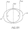
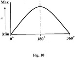
- Dispositif magnétique pouvant commuter du type comprenant un boîtier (12, 13), un premier aimant permanent (10), un second aimant permanent (11), les premier et second aimants permanents étant montés à l'intérieur du boîtier (12, 13) de sorte que les premier et second aimants permanents (10 ; 11) puissent tourner l'un par rapport à l'autre, et un moyen d'actionnement (22) apte à provoquer une rotation relative desdits premier et second aimants permanents (10 ; 11), dans lequel les premier et second aimants sont rotatifs l'un par rapport à l'autre entre une position « complètement hors circuit » dans laquelle des pôles nord et sud du premier aimant permanent (10) sont respectivement alignés avec des pôles sud et nord du second aimant permanent (11) et le dispositif magnétique affiche un champ magnétique externe minimal, et une position « complètement en circuit » dans laquelle les pôles nord et sud du premier aimant permanent (10) sont positionnés en alignement respectif avec les pôles nord et sud du second aimant permanent (11) et le dispositif magnétique affiche un champ magnétique externe maximal,
caractérisé en ce que le dispositif magnétique peut être placé en contact avec un matériau ferromagnétique externe (1050, 1230, 1305, 1420,1730) pouvant être fixé de manière libérable au dispositif magnétique, ou à proximité immédiate de ce dernier, le dispositif magnétique comprenant en outre(a) un moyen de mise en circuit automatique (21, 30) conçu pour commuter automatiquement le dispositif magnétique vers une position « en circuit », dans laquelle le dispositif magnétique affiche un champ magnétique externe relativement puissant, lorsque le dispositif magnétique est amené en contact avec le matériau ferromagnétique externe, ou à proximité immédiate de ce dernier, et/ou(b) un moyen de mise hors circuit automatique (33) conçu pour commuter automatiquement le dispositif magnétique vers une position « hors circuit », dans laquelle le dispositif magnétique affiche un champ magnétique externe relativement faible, lorsque le dispositif magnétique est dégagé du contact avec le matériau ferromagnétique externe, ou de sa proximité immédiate avec ce dernier,en ce que le moyen de mise en circuit automatique (21, 30) comprend un moyen de sollicitation (30) associé de manière fonctionnelle aux premier et second aimants permanents (10 ; 11) pour solliciter la position de rotation relative des premier et second aimants permanents (10 ; 11) à l'écart de la position « complètement hors circuit » et provoquer la rotation relative des premier et second aimants permanents en direction de la position « complètement en circuit » lorsque le dispositif est placé sur le matériau ferromagnétique externe, ou à proximité immédiate de ce dernier,
et en ce que le moyen de mise hors circuit automatique comprend un moyen de limitation de rotation (33) associé de manière fonctionnelle avec l'un, rotatif, des premier et second aimants permanents (10 ; 11) pour maintenir de façon libérable l'aimant permettant rotatif (10) dans une position de rotation dans laquelle le dispositif magnétique affiche un champ magnétique externe puissant et qui est proche de la position « complètement en circuit », mais décalée en rotation de cette dernière. - Dispositif magnétique selon la revendication 1, dans lequel les premier et second aimants permanents (10 ; 11) ont une forme cylindrique ou de disque, sont polarisés diamétralement et sont empilés l'un sur l'autre à l'intérieur du boîtier (12, 13) de façon à pouvoir tourner l'un par rapport à l'autre autour d'un axe commun passant par un point central des premier et second aimants permanents (10 ; 11).
- Dispositif magnétique selon la revendication 1 ou 2, dans lequel le moyen de sollicitation (30) est conçu pour appliquer une force de rotation (F) servant à provoquer une rotation relative des premier et second aimants permanents (10 ; 11) en direction de la position « complètement en circuit » ayant une valeur qui est inférieure à une première force maximale de rotation (F2) nécessaire à provoquer une rotation relative des premier et second aimants permanents (10 ; 11) en direction de la position « complètement en circuit » lorsque le dispositif magnétique n'est pas en contact avec le matériau ferromagnétique, ni à proximité immédiate de ce dernier, mais ayant une valeur supérieure à une seconde force maximale de rotation (F1) nécessaire à provoquer une rotation relative des premier et second aimants permanents (10 ; 11) en direction de la position « complètement en circuit » lorsque le dispositif magnétique est en contact avec le matériau ferromagnétique externe ou à proximité immédiate de ce dernier.
- Dispositif magnétique selon la revendication 3, dans lequel la force de sollicitation (F) a une valeur telle que les pôles nord et sud de l'aimant permanent rotatif des premier et second aimants permanents (10; 11) sont respectivement décalés en rotation de la position « complètement hors circuit » d'un angle de 10 à 60 degrés, on préfère de 30 degrés, lorsque le dispositif magnétique n'est pas en contact avec le matériau ferromagnétique externe, ni à proximité immédiate de ce dernier.
- Dispositif magnétique selon la revendication 3 ou 4, dans lequel le moyen de sollicitation (30) est un ressort.
- Dispositif magnétique selon l'une quelconque des revendications 1 à 5, dans lequel le moyen de limitation de rotation (33) est conçu pour permettre une rotation relative des premier et second aimants permanents (10 ; 11) d'un état activé, dans lequel le dispositif magnétique affiche un champ magnétique externe relativement puissant, à un état désactivé, dans lequel le dispositif magnétique affiche un champ magnétique externe relativement faible, lorsque le dispositif magnétique n'est plus en contact avec le matériau ferromagnétique externe, ou à proximité immédiate de ce dernier.
- Dispositif magnétique selon la revendication 6, dans lequel, dans l'état désactivé, les pôles nord et sud du premier aimant permanent (10) et les pôles sud et nord du second aimant permanent (11) sont respectivement décalés en rotation d'un angle inférieur ou égal à 50 degrés, on préfère inférieur ou égal à 30 degrés.
- Dispositif magnétique selon la revendication 6, dans lequel, dans l'état désactivé, les pôles nord et sud du premier aimant permanent (10) et les pôles sud et nord du second aimant permanent (11) sont respectivement alignés en rotation et le dispositif magnétique est dans la position « complètement hors circuit ».
- Dispositif magnétique selon la revendication 6, dans lequel, dans l'état activé, les pôles nord et sud du premier aimant permanent (10) et les pôles nord et sud du second aimant permanent (11) sont respectivement décalés en rotation d'un angle inférieur ou égal à 15 degrés, on préfère d'environ 10 degrés.
- Dispositif magnétique selon l'une quelconque des revendications 6 à 9, dans lequel le moyen de limitation de rotation (33) est conçu pour limiter la rotation relative des premier et second aimants permanents (10 ; 11) sur un angle inférieur ou égal à 180 degrés.
- Dispositif magnétique selon la revendication 6, dans lequel le moyen de limitation de rotation (33) est conçu pour empêcher que les premier et second aimants permanents (10 ; 11) ne viennent dans la position « complètement en circuit ».
- Dispositif magnétique selon la revendication 11, dans lequel le moyen de limitation de rotation (33) comprend un moyen de butée conçu pour soit (i) empêcher une rotation du moyen d'actionnement (22) pour commuter l'aimant permanent mobile des premier et second aimants permanents (10 ; 11) dans la position « complètement en circuit » soit (ii) contacter sélectivement l'aimant permanent mobile des premier et second aimants permanents (10 ; 11) pour empêcher une rotation de ce dernier dans la position « complètement en circuit ».
- Dispositif selon la revendication 6, dans lequel le moyen de limitation de rotation est conçu pour appliquer une force de retenue visant à retenir l'aimant mobile des premier et second aimants permanents (10 ; 11) dans la position activée lorsque le dispositif magnétique est en contact avec le matériau ferromagnétique externe, ou à proximité immédiate de ce dernier, la force de retenue appliquée pour maintenir les aimants permanents (10 ; 11) dans la position activée étant supérieure à une première force nécessaire pour maintenir les aimants permanents (10 ; 11) dans l'état activé lorsque le dispositif magnétique est en contact avec le matériau ferromagnétique externe, ou à proximité immédiate de ce dernier, mais inférieure à une seconde force nécessaire pour maintenir les aimants permanents (10 ; 11) dans l'état activé lorsque le dispositif magnétique n'est pas en contact avec le matériau ferromagnétique externe, ni à proximité immédiate de ce dernier, permettant ainsi au ou aux aimants mobiles des premier et second aimants permanents (10 ; 11) de tourner automatiquement en direction de l'état désactivé lorsque le dispositif magnétique n'est plus dans une position de contact avec le matériau ferromagnétique externe ou de proximité immédiate avec ce dernier.
- Dispositif magnétique selon la revendication 13, dans lequel la force de retenue est une force de frottement générée par l'aimant permanent mobile des aimants permanents (10 ; 11) à l'intérieur du boîtier (12, 13) du dispositif magnétique.
- Dispositif selon la revendication 13, dans lequel le moyen de limitation de rotation comprend un dispositif de retenue conçu pour appliquer la force de retenue visant à retenir le ou les aimants permanents mobiles des premier et second aimants permanents (10 ; 11) dans la position activée lorsque le dispositif magnétique est en contact avec le matériau ferromagnétique externe, ou à proximité immédiate de ce dernier, le dispositif de retenue comprenant de préférence un moyen de verrouillage qui se déforme élastiquement lors de l'application d'une force prédéterminée qui est inférieure à la seconde force mais qui est supérieure à la première force.
- Dispositif magnétique selon la revendication 1 ou 2, dans lequel le moyen de limitation de rotation (33) est conçu pour permettre une rotation relative des premier et second aimants permanents (10 ; 11) d'un état désactivé, dans lequel le dispositif magnétique affiche un champ magnétique externe relativement faible, au-delà de la position « complètement en circuit » dans un état activé dans lequel les pôles nord et sud du premier aimant permanent (10) et les pôles sud et nord du second aimant permanent (11) sont respectivement décalés en rotation d'un certain angle et dans lequel le dispositif magnétique affiche un champ magnétique externe relativement puissant, de sorte que le dispositif magnétique demeure dans l'état activé lorsqu'il n'est plus en contact avec le matériau ferromagnétique externe, ou à proximité immédiate de ce dernier, le moyen de limitation de rotation (33) comprenant un élément de butée conçu pour contacter sélectivement l'aimant permanent mobile des premier et second aimants permanents (10 ; 11) dans l'état activé.
- Dispositif magnétique selon la revendication 1 ou 2, dans lequel le moyen d'actionnement (22) comprend une partie flexible conçue pour se déformer lorsque le moyen d'actionnement (22) est actionné et que le dispositif magnétique n'est pas en contact avec le matériau ferromagnétique externe, ni à proximité immédiate de ce dernier, pour ainsi limiter la rotation relative de l'aimant permanent rotatif des premier et second aimants permanents (10 ; 11), ladite partie flexible ayant une résistance à la déformation élastique suffisante pour éviter une déformation pendant l'actionnement dudit moyen d'actionnement (22) lorsque le dispositif magnétique est en contact avec le matériau ferromagnétique externe, ou à proximité immédiate de ce dernier, ladite partie flexible étant de préférence une liaison à ressort (50).
- Dispositif magnétique selon la revendication 17, dans lequel ladite partie flexible est conçue de sorte qu'elle peut se déformer dans une mesure maximale, et dans lequel le moyen d'actionnement est conçu pour provoquer une rotation relative de l'aimant permanent rotatif des premier et second aimants permanents (10 ; 11) après la déformation de la partie flexible dans la mesure maximale.
- Dispositif magnétique selon l'une quelconque des revendications 2, 3, 6, ou 16, dans lequel le dispositif magnétique est assemblé à partir de modules individuels comprenant un module de base (2000) incorporant les premier et second aimants permanents (10 ; 11) disposés à l'intérieur d'une chambre du boîtier, un actionneur (2070) conçu pour permettre une rotation relative sélective de l'aimant permanent rotatif des premier et second aimants permanents (10 ; 11) pour commuter le dispositif magnétique entre une position « complètement en circuit » et une position « complètement hors circuit », et un ou plusieurs modules (2020 ; 2030) conçus pour mettre en oeuvre la fonctionnalité de sollicitation et de limitation de rotation selon les revendications 1, 3, 6 ou 16.
- Dispositif selon la revendication 19, comprenant en outre un module de sélection d'opération (2040) conçu pour activer et désactiver sélectivement un ou plusieurs des modules de mise en circuit automatique et de mise hors circuit automatique (2020 ; 2030).
Applications Claiming Priority (15)
| Application Number | Priority Date | Filing Date | Title |
|---|---|---|---|
| AUPR725101 | 2001-08-24 | ||
| AUPR7251A AUPR725101A0 (en) | 2001-08-24 | 2001-08-24 | Switchable magnetic device |
| US09/951,905 US6707360B2 (en) | 1999-12-06 | 2001-09-14 | Switchable permanent magnetic device |
| US951905 | 2001-09-14 | ||
| AUPR997502 | 2002-01-17 | ||
| AUPR9975A AUPR997502A0 (en) | 2002-01-17 | 2002-01-17 | Holding device (vacuum pad) |
| AUPS0091A AUPS009102A0 (en) | 2002-01-23 | 2002-01-23 | Locking mechanism for cutlery blocks |
| AUPS009102 | 2002-01-23 | ||
| AUPS033802 | 2002-02-07 | ||
| AUPS0338A AUPS033802A0 (en) | 2002-02-07 | 2002-02-07 | Transport system for car roofs |
| AUPS1083A AUPS108302A0 (en) | 2002-03-14 | 2002-03-14 | Magnetic latches |
| AUPS108302 | 2002-03-14 | ||
| AUPS1168A AUPS116802A0 (en) | 2002-03-19 | 2002-03-19 | Device for turning/positioning of satellites operating within a magnetic field |
| AUPS116802 | 2002-03-19 | ||
| PCT/AU2002/001156 WO2003019583A1 (fr) | 2001-08-24 | 2002-08-26 | Dispositif magnetique commutable |
Publications (3)
| Publication Number | Publication Date |
|---|---|
| EP1425763A1 EP1425763A1 (fr) | 2004-06-09 |
| EP1425763A4 EP1425763A4 (fr) | 2009-12-23 |
| EP1425763B1 true EP1425763B1 (fr) | 2017-02-15 |
Family
ID=27560732
Family Applications (1)
| Application Number | Title | Priority Date | Filing Date |
|---|---|---|---|
| EP02757967.1A Expired - Lifetime EP1425763B1 (fr) | 2001-08-24 | 2002-08-26 | Dispositif magnetique commutable |
Country Status (8)
| Country | Link |
|---|---|
| EP (1) | EP1425763B1 (fr) |
| JP (1) | JP4567971B2 (fr) |
| CN (2) | CN100338697C (fr) |
| BR (1) | BRPI0212711B1 (fr) |
| CA (1) | CA2458251C (fr) |
| EA (1) | EA006279B1 (fr) |
| MX (1) | MXPA04001694A (fr) |
| WO (1) | WO2003019583A1 (fr) |
Cited By (2)
| Publication number | Priority date | Publication date | Assignee | Title |
|---|---|---|---|---|
| US11482359B2 (en) | 2020-02-20 | 2022-10-25 | Magnetic Mechanisms L.L.C. | Detachable magnet device |
| EP4051059A4 (fr) * | 2019-10-30 | 2023-11-29 | Schmidt Brothers, Inc. | Support de couteaux verrouillable |
Families Citing this family (27)
| Publication number | Priority date | Publication date | Assignee | Title |
|---|---|---|---|---|
| FR2893494B1 (fr) | 2005-11-23 | 2013-04-05 | Seb Sa | Organe de prehension de couvercle aimante |
| KR101455407B1 (ko) * | 2006-03-13 | 2014-10-27 | 맥스위치 테크놀로지 월드와이드 피티와이 리미티드 | 자석식 휠 |
| WO2012108477A1 (fr) * | 2011-02-08 | 2012-08-16 | 株式会社ジェイテクト | Appareil de détection de couple |
| US9354748B2 (en) | 2012-02-13 | 2016-05-31 | Microsoft Technology Licensing, Llc | Optical stylus interaction |
| US9460029B2 (en) | 2012-03-02 | 2016-10-04 | Microsoft Technology Licensing, Llc | Pressure sensitive keys |
| US9870066B2 (en) | 2012-03-02 | 2018-01-16 | Microsoft Technology Licensing, Llc | Method of manufacturing an input device |
| US9075566B2 (en) | 2012-03-02 | 2015-07-07 | Microsoft Technoogy Licensing, LLC | Flexible hinge spine |
| US8873227B2 (en) | 2012-03-02 | 2014-10-28 | Microsoft Corporation | Flexible hinge support layer |
| EP2864991B1 (fr) * | 2012-06-20 | 2023-07-26 | Inelxia Limited | Mécanisme de connexion et de déconnexion de deux pièces |
| US8964379B2 (en) | 2012-08-20 | 2015-02-24 | Microsoft Corporation | Switchable magnetic lock |
| US10120420B2 (en) | 2014-03-21 | 2018-11-06 | Microsoft Technology Licensing, Llc | Lockable display and techniques enabling use of lockable displays |
| KR20170069995A (ko) * | 2014-07-09 | 2017-06-21 | 맥스위치 테크놀로지 인코포레이티드 | 자기 공구 스탠드 |
| US10324733B2 (en) | 2014-07-30 | 2019-06-18 | Microsoft Technology Licensing, Llc | Shutdown notifications |
| CN107889454B (zh) * | 2015-03-12 | 2021-06-22 | Gi视窗公司 | 在一定距离处具有变化磁力的磁性吻合装置 |
| EP3297545A1 (fr) * | 2015-05-08 | 2018-03-28 | GI Windows Inc. | Systèmes, dispositifs et procédés de formation d'anastomoses |
| US9739218B2 (en) * | 2015-10-06 | 2017-08-22 | Kohler Co. | Throttle drive actuator for an engine |
| GB2560532B (en) * | 2017-03-14 | 2019-10-30 | Adey Holdings 2008 Ltd | Modular magnetic assembly |
| JP7333309B2 (ja) | 2017-04-27 | 2023-08-24 | マグスウィッチ テクノロジー ワールドワイド プロプライエタリー リミテッド | センサ構成及び消磁機能のうちの少なくとも一方を備えた磁気結合デバイス |
| US10903030B2 (en) | 2017-04-27 | 2021-01-26 | Magswitch Technology Worldwide Pty Ltd. | Variable field magnetic couplers and methods for engaging a ferromagnetic workpiece |
| MX2019014709A (es) | 2017-06-08 | 2020-08-17 | Magswitch Tech Worldwide Pty Ltd | Dispositivo de iman permanente conmutable por electroiman. |
| US10658099B2 (en) * | 2017-08-16 | 2020-05-19 | Daktronics, Inc. | Magnetic latch for a display module |
| CN107738277B (zh) * | 2017-11-22 | 2020-05-19 | 中国人民解放军战略支援部队航天工程大学 | 一种太空服务机器人及其组装方法和拆分方法 |
| CN111742382B (zh) * | 2017-12-21 | 2023-01-06 | 理想工业公司 | 可转换力闩锁系统 |
| IT201800006207A1 (it) * | 2018-06-11 | 2019-12-11 | Modulo magnetico con superfici di ancoraggio attivabili e disattivabili magneticamente | |
| CN109987537A (zh) * | 2019-03-24 | 2019-07-09 | 宁波天胜传动件有限公司 | 一种安全稳固的剪式千斤顶及其使用方法 |
| EP4179930A1 (fr) * | 2021-11-10 | 2023-05-17 | Versuni Holding B.V. | Appareil de cuisine |
| CN115862996B (zh) * | 2023-02-20 | 2023-04-28 | 苏州无双医疗设备有限公司 | 医疗设备触发器 |
Family Cites Families (17)
| Publication number | Priority date | Publication date | Assignee | Title |
|---|---|---|---|---|
| DE1613034A1 (de) * | 1967-10-06 | 1971-04-08 | Max Baermann | Durch Gleichstromimpulse schalt- und regelbares,polarisiertes Magnetsystem,vorzugsweise fuer Wirbelstrom- und/oder Hysteresebremsen bzw.-kupplungen |
| DE3220801A1 (de) * | 1982-06-03 | 1984-01-26 | Max Baermann GmbH, 5060 Bergisch Gladbach | Schaltbare, dauermagnetische haltevorrichtung |
| JPS5982635U (ja) * | 1982-11-24 | 1984-06-04 | 鐘通工業株式会社 | 切換可能の永久磁石チヤツク |
| US4419644A (en) * | 1983-01-14 | 1983-12-06 | Max Baermann Gmbh | Switchable permanent magnetic holding device |
| US4639170A (en) * | 1985-04-08 | 1987-01-27 | Milwaukee Electric Tool Corporation | Magnetic base for portable tools |
| JPH0423892Y2 (fr) * | 1987-05-25 | 1992-06-04 | ||
| GB2211356A (en) * | 1987-10-16 | 1989-06-28 | Holdings James Neill | Magnetic work holders |
| JPH084661B2 (ja) * | 1989-03-20 | 1996-01-24 | 株式会社タカラ | ステージ玩具装置 |
| US5170144A (en) * | 1989-07-31 | 1992-12-08 | Solatrol, Inc. | High efficiency, flux-path-switching, electromagnetic actuator |
| SU1763341A1 (ru) * | 1989-09-05 | 1992-09-23 | Н.В. Мудров и А.Н. Мудров | Магнитное грузозахватное устройство |
| JP2511324B2 (ja) * | 1990-12-28 | 1996-06-26 | 株式会社応用技術研究所 | 磁気掛止具 |
| FR2675299B1 (fr) * | 1991-04-10 | 1994-09-16 | Braillon Cie | Porteur magnetique a aimants permanents. |
| US5270678A (en) * | 1992-03-06 | 1993-12-14 | Walker Magnetics Group, Inc. | Magnetic rail chuck |
| DE19710186A1 (de) * | 1997-02-28 | 1998-09-03 | Manfred Dipl Ing Stelter | Dauermagnetische Koppelvorrichtung |
| JPH10288191A (ja) * | 1997-04-16 | 1998-10-27 | Daikin Ind Ltd | ポンプ |
| AUPQ446699A0 (en) * | 1999-12-06 | 2000-01-06 | Kocijan, Franz | Switchable (variable) permanent magnet device |
| US6501357B2 (en) * | 2000-03-16 | 2002-12-31 | Quizix, Inc. | Permanent magnet actuator mechanism |
-
2002
- 2002-08-26 BR BRPI0212711A patent/BRPI0212711B1/pt not_active IP Right Cessation
- 2002-08-26 MX MXPA04001694A patent/MXPA04001694A/es active IP Right Grant
- 2002-08-26 EA EA200400350A patent/EA006279B1/ru not_active IP Right Cessation
- 2002-08-26 EP EP02757967.1A patent/EP1425763B1/fr not_active Expired - Lifetime
- 2002-08-26 CA CA2458251A patent/CA2458251C/fr not_active Expired - Fee Related
- 2002-08-26 CN CNB028201698A patent/CN100338697C/zh not_active Expired - Fee Related
- 2002-08-26 WO PCT/AU2002/001156 patent/WO2003019583A1/fr active Application Filing
- 2002-08-26 JP JP2003522954A patent/JP4567971B2/ja not_active Expired - Fee Related
- 2002-08-26 CN CN2006101362382A patent/CN1963962B/zh not_active Expired - Fee Related
Non-Patent Citations (1)
| Title |
|---|
| None * |
Cited By (2)
| Publication number | Priority date | Publication date | Assignee | Title |
|---|---|---|---|---|
| EP4051059A4 (fr) * | 2019-10-30 | 2023-11-29 | Schmidt Brothers, Inc. | Support de couteaux verrouillable |
| US11482359B2 (en) | 2020-02-20 | 2022-10-25 | Magnetic Mechanisms L.L.C. | Detachable magnet device |
Also Published As
| Publication number | Publication date |
|---|---|
| MXPA04001694A (es) | 2004-05-31 |
| EP1425763A1 (fr) | 2004-06-09 |
| CN100338697C (zh) | 2007-09-19 |
| BR0212711A (pt) | 2004-11-23 |
| CA2458251A1 (fr) | 2003-03-06 |
| CA2458251C (fr) | 2012-02-28 |
| EA006279B1 (ru) | 2005-10-27 |
| CN1963962A (zh) | 2007-05-16 |
| EP1425763A4 (fr) | 2009-12-23 |
| WO2003019583A1 (fr) | 2003-03-06 |
| CN1963962B (zh) | 2012-07-04 |
| EA200400350A1 (ru) | 2004-08-26 |
| JP4567971B2 (ja) | 2010-10-27 |
| JP2005500697A (ja) | 2005-01-06 |
| CN1568527A (zh) | 2005-01-19 |
| BRPI0212711B1 (pt) | 2017-04-18 |
Similar Documents
| Publication | Publication Date | Title |
|---|---|---|
| EP1425763B1 (fr) | Dispositif magnetique commutable | |
| US20040239460A1 (en) | Switchable magnetic device | |
| US11031166B2 (en) | Electromagnet-switchable permanent magnet device | |
| EP0047264B1 (fr) | Decoupleur magnetique | |
| JP3619693B2 (ja) | 磁力吸着器の吸着磁力自動開閉装置 | |
| US6084498A (en) | Magnetic decoupler | |
| US5271253A (en) | Electronic combination lock with magnetic anti-attack interlock | |
| JPS61257707A (ja) | 電動工具 | |
| AU2002325077B2 (en) | Switchable magnetic device | |
| EP0485501A1 (fr) | Actuateur electromagnetique a haute efficacite et a commutation du cheminement du flux | |
| AU2002325077A1 (en) | Switchable magnetic device | |
| AU753496B2 (en) | Switchable permanent magnetic device | |
| US20190214941A1 (en) | Panel with Magnetically-Controlled Connectors for Attachment to a Support Member | |
| US20230333463A1 (en) | Reticle container having magnetic latching | |
| GB2395744A (en) | Magnetic retaining device | |
| JPH0545718Y2 (fr) | ||
| JPH0435343Y2 (fr) | ||
| JPS59214532A (ja) | 永久磁石チヤツク |
Legal Events
| Date | Code | Title | Description |
|---|---|---|---|
| PUAI | Public reference made under article 153(3) epc to a published international application that has entered the european phase |
Free format text: ORIGINAL CODE: 0009012 |
|
| 17P | Request for examination filed |
Effective date: 20040318 |
|
| AK | Designated contracting states |
Kind code of ref document: A1 Designated state(s): AT BE BG CH CY CZ DE DK EE ES FI FR GB GR IE IT LI LU MC NL PT SE SK TR |
|
| AX | Request for extension of the european patent |
Extension state: AL LT LV MK RO SI |
|
| REG | Reference to a national code |
Ref country code: HK Ref legal event code: DE Ref document number: 1066913 Country of ref document: HK |
|
| A4 | Supplementary search report drawn up and despatched |
Effective date: 20091123 |
|
| 17Q | First examination report despatched |
Effective date: 20100709 |
|
| GRAP | Despatch of communication of intention to grant a patent |
Free format text: ORIGINAL CODE: EPIDOSNIGR1 |
|
| INTG | Intention to grant announced |
Effective date: 20160602 |
|
| GRAJ | Information related to disapproval of communication of intention to grant by the applicant or resumption of examination proceedings by the epo deleted |
Free format text: ORIGINAL CODE: EPIDOSDIGR1 |
|
| GRAP | Despatch of communication of intention to grant a patent |
Free format text: ORIGINAL CODE: EPIDOSNIGR1 |
|
| INTC | Intention to grant announced (deleted) | ||
| GRAJ | Information related to disapproval of communication of intention to grant by the applicant or resumption of examination proceedings by the epo deleted |
Free format text: ORIGINAL CODE: EPIDOSDIGR1 |
|
| INTG | Intention to grant announced |
Effective date: 20161111 |
|
| GRAS | Grant fee paid |
Free format text: ORIGINAL CODE: EPIDOSNIGR3 |
|
| GRAP | Despatch of communication of intention to grant a patent |
Free format text: ORIGINAL CODE: EPIDOSNIGR1 |
|
| INTC | Intention to grant announced (deleted) | ||
| GRAA | (expected) grant |
Free format text: ORIGINAL CODE: 0009210 |
|
| INTG | Intention to grant announced |
Effective date: 20170102 |
|
| AK | Designated contracting states |
Kind code of ref document: B1 Designated state(s): AT BE BG CH CY CZ DE DK EE ES FI FR GB GR IE IT LI LU MC NL PT SE SK TR |
|
| REG | Reference to a national code |
Ref country code: CH Ref legal event code: EP Ref country code: GB Ref legal event code: FG4D |
|
| REG | Reference to a national code |
Ref country code: DE Ref legal event code: R081 Ref document number: 60248672 Country of ref document: DE Owner name: MAGSWITCH TECHNOLOGY EUROPE GMBH, DE Free format text: FORMER OWNER: THE AUSSIE KIDS TOY CO. PTY. LTD., PORT MACQUARIE, NSW, AU |
|
| REG | Reference to a national code |
Ref country code: IE Ref legal event code: FG4D |
|
| REG | Reference to a national code |
Ref country code: AT Ref legal event code: REF Ref document number: 868302 Country of ref document: AT Kind code of ref document: T Effective date: 20170315 |
|
| REG | Reference to a national code |
Ref country code: DE Ref legal event code: R096 Ref document number: 60248672 Country of ref document: DE |
|
| REG | Reference to a national code |
Ref country code: NL Ref legal event code: MP Effective date: 20170215 |
|
| REG | Reference to a national code |
Ref country code: FR Ref legal event code: PLFP Year of fee payment: 16 |
|
| REG | Reference to a national code |
Ref country code: AT Ref legal event code: MK05 Ref document number: 868302 Country of ref document: AT Kind code of ref document: T Effective date: 20170215 |
|
| PG25 | Lapsed in a contracting state [announced via postgrant information from national office to epo] |
Ref country code: FI Free format text: LAPSE BECAUSE OF FAILURE TO SUBMIT A TRANSLATION OF THE DESCRIPTION OR TO PAY THE FEE WITHIN THE PRESCRIBED TIME-LIMIT Effective date: 20170215 Ref country code: GR Free format text: LAPSE BECAUSE OF FAILURE TO SUBMIT A TRANSLATION OF THE DESCRIPTION OR TO PAY THE FEE WITHIN THE PRESCRIBED TIME-LIMIT Effective date: 20170516 |
|
| PG25 | Lapsed in a contracting state [announced via postgrant information from national office to epo] |
Ref country code: ES Free format text: LAPSE BECAUSE OF FAILURE TO SUBMIT A TRANSLATION OF THE DESCRIPTION OR TO PAY THE FEE WITHIN THE PRESCRIBED TIME-LIMIT Effective date: 20170215 Ref country code: PT Free format text: LAPSE BECAUSE OF FAILURE TO SUBMIT A TRANSLATION OF THE DESCRIPTION OR TO PAY THE FEE WITHIN THE PRESCRIBED TIME-LIMIT Effective date: 20170615 Ref country code: BG Free format text: LAPSE BECAUSE OF FAILURE TO SUBMIT A TRANSLATION OF THE DESCRIPTION OR TO PAY THE FEE WITHIN THE PRESCRIBED TIME-LIMIT Effective date: 20170515 Ref country code: SE Free format text: LAPSE BECAUSE OF FAILURE TO SUBMIT A TRANSLATION OF THE DESCRIPTION OR TO PAY THE FEE WITHIN THE PRESCRIBED TIME-LIMIT Effective date: 20170215 Ref country code: AT Free format text: LAPSE BECAUSE OF FAILURE TO SUBMIT A TRANSLATION OF THE DESCRIPTION OR TO PAY THE FEE WITHIN THE PRESCRIBED TIME-LIMIT Effective date: 20170215 Ref country code: NL Free format text: LAPSE BECAUSE OF FAILURE TO SUBMIT A TRANSLATION OF THE DESCRIPTION OR TO PAY THE FEE WITHIN THE PRESCRIBED TIME-LIMIT Effective date: 20170215 |
|
| REG | Reference to a national code |
Ref country code: DE Ref legal event code: R082 Ref document number: 60248672 Country of ref document: DE Representative=s name: FARAGO PATENTANWAELTE, DE Ref country code: DE Ref legal event code: R081 Ref document number: 60248672 Country of ref document: DE Owner name: MAGSWITCH TECHNOLOGY EUROPE GMBH, DE Free format text: FORMER OWNER: THE AUSSIE KIDS TOY CO. PTY. LTD., PORT MACQUARIE, NSW, AU Ref country code: DE Ref legal event code: R082 Ref document number: 60248672 Country of ref document: DE Representative=s name: FARAGO PATENTANWALTS- UND RECHTSANWALTSGESELLS, DE |
|
| RAP4 | Party data changed (patent owner data changed or rights of a patent transferred) |
Owner name: AUSSIE KIDS TOY COMPANY PTY. LIMITED |
|
| RAP2 | Party data changed (patent owner data changed or rights of a patent transferred) |
Owner name: MAGSWITCH TECHNOLOGY EUROPE GMBH |
|
| PG25 | Lapsed in a contracting state [announced via postgrant information from national office to epo] |
Ref country code: IT Free format text: LAPSE BECAUSE OF FAILURE TO SUBMIT A TRANSLATION OF THE DESCRIPTION OR TO PAY THE FEE WITHIN THE PRESCRIBED TIME-LIMIT Effective date: 20170215 Ref country code: SK Free format text: LAPSE BECAUSE OF FAILURE TO SUBMIT A TRANSLATION OF THE DESCRIPTION OR TO PAY THE FEE WITHIN THE PRESCRIBED TIME-LIMIT Effective date: 20170215 Ref country code: CZ Free format text: LAPSE BECAUSE OF FAILURE TO SUBMIT A TRANSLATION OF THE DESCRIPTION OR TO PAY THE FEE WITHIN THE PRESCRIBED TIME-LIMIT Effective date: 20170215 Ref country code: EE Free format text: LAPSE BECAUSE OF FAILURE TO SUBMIT A TRANSLATION OF THE DESCRIPTION OR TO PAY THE FEE WITHIN THE PRESCRIBED TIME-LIMIT Effective date: 20170215 |
|
| REG | Reference to a national code |
Ref country code: GB Ref legal event code: 732E Free format text: REGISTERED BETWEEN 20171019 AND 20171025 |
|
| REG | Reference to a national code |
Ref country code: DE Ref legal event code: R097 Ref document number: 60248672 Country of ref document: DE |
|
| PG25 | Lapsed in a contracting state [announced via postgrant information from national office to epo] |
Ref country code: DK Free format text: LAPSE BECAUSE OF FAILURE TO SUBMIT A TRANSLATION OF THE DESCRIPTION OR TO PAY THE FEE WITHIN THE PRESCRIBED TIME-LIMIT Effective date: 20170215 |
|
| PLBE | No opposition filed within time limit |
Free format text: ORIGINAL CODE: 0009261 |
|
| STAA | Information on the status of an ep patent application or granted ep patent |
Free format text: STATUS: NO OPPOSITION FILED WITHIN TIME LIMIT |
|
| 26N | No opposition filed |
Effective date: 20171116 |
|
| REG | Reference to a national code |
Ref country code: CH Ref legal event code: PL |
|
| PG25 | Lapsed in a contracting state [announced via postgrant information from national office to epo] |
Ref country code: MC Free format text: LAPSE BECAUSE OF FAILURE TO SUBMIT A TRANSLATION OF THE DESCRIPTION OR TO PAY THE FEE WITHIN THE PRESCRIBED TIME-LIMIT Effective date: 20170215 |
|
| PG25 | Lapsed in a contracting state [announced via postgrant information from national office to epo] |
Ref country code: CH Free format text: LAPSE BECAUSE OF NON-PAYMENT OF DUE FEES Effective date: 20170831 Ref country code: LI Free format text: LAPSE BECAUSE OF NON-PAYMENT OF DUE FEES Effective date: 20170831 |
|
| REG | Reference to a national code |
Ref country code: FR Ref legal event code: TP Owner name: MAGSWITCH TECHNOLOGY EUROPE GMBH, DE Effective date: 20180330 |
|
| REG | Reference to a national code |
Ref country code: IE Ref legal event code: MM4A |
|
| REG | Reference to a national code |
Ref country code: BE Ref legal event code: MM Effective date: 20170831 |
|
| PG25 | Lapsed in a contracting state [announced via postgrant information from national office to epo] |
Ref country code: LU Free format text: LAPSE BECAUSE OF NON-PAYMENT OF DUE FEES Effective date: 20170826 |
|
| REG | Reference to a national code |
Ref country code: FR Ref legal event code: PLFP Year of fee payment: 17 |
|
| PG25 | Lapsed in a contracting state [announced via postgrant information from national office to epo] |
Ref country code: IE Free format text: LAPSE BECAUSE OF NON-PAYMENT OF DUE FEES Effective date: 20170826 |
|
| PG25 | Lapsed in a contracting state [announced via postgrant information from national office to epo] |
Ref country code: BE Free format text: LAPSE BECAUSE OF NON-PAYMENT OF DUE FEES Effective date: 20170831 |
|
| PG25 | Lapsed in a contracting state [announced via postgrant information from national office to epo] |
Ref country code: CY Free format text: LAPSE BECAUSE OF NON-PAYMENT OF DUE FEES Effective date: 20170215 |
|
| PGFP | Annual fee paid to national office [announced via postgrant information from national office to epo] |
Ref country code: FR Payment date: 20191113 Year of fee payment: 18 |
|
| PG25 | Lapsed in a contracting state [announced via postgrant information from national office to epo] |
Ref country code: TR Free format text: LAPSE BECAUSE OF FAILURE TO SUBMIT A TRANSLATION OF THE DESCRIPTION OR TO PAY THE FEE WITHIN THE PRESCRIBED TIME-LIMIT Effective date: 20170215 |
|
| REG | Reference to a national code |
Ref country code: HK Ref legal event code: WD Ref document number: 1066913 Country of ref document: HK |
|
| PGFP | Annual fee paid to national office [announced via postgrant information from national office to epo] |
Ref country code: GB Payment date: 20191030 Year of fee payment: 18 |
|
| PGFP | Annual fee paid to national office [announced via postgrant information from national office to epo] |
Ref country code: DE Payment date: 20200812 Year of fee payment: 19 |
|
| GBPC | Gb: european patent ceased through non-payment of renewal fee |
Effective date: 20200826 |
|
| PG25 | Lapsed in a contracting state [announced via postgrant information from national office to epo] |
Ref country code: FR Free format text: LAPSE BECAUSE OF NON-PAYMENT OF DUE FEES Effective date: 20200831 |
|
| PG25 | Lapsed in a contracting state [announced via postgrant information from national office to epo] |
Ref country code: GB Free format text: LAPSE BECAUSE OF NON-PAYMENT OF DUE FEES Effective date: 20200826 |
|
| REG | Reference to a national code |
Ref country code: DE Ref legal event code: R119 Ref document number: 60248672 Country of ref document: DE |
|
| PG25 | Lapsed in a contracting state [announced via postgrant information from national office to epo] |
Ref country code: DE Free format text: LAPSE BECAUSE OF NON-PAYMENT OF DUE FEES Effective date: 20220301 |