EP1424663A2 - Gaming Machine - Google Patents
Gaming Machine Download PDFInfo
- Publication number
- EP1424663A2 EP1424663A2 EP03026651A EP03026651A EP1424663A2 EP 1424663 A2 EP1424663 A2 EP 1424663A2 EP 03026651 A EP03026651 A EP 03026651A EP 03026651 A EP03026651 A EP 03026651A EP 1424663 A2 EP1424663 A2 EP 1424663A2
- Authority
- EP
- European Patent Office
- Prior art keywords
- payout
- reel
- winning combination
- winning
- game
- Prior art date
- Legal status (The legal status is an assumption and is not a legal conclusion. Google has not performed a legal analysis and makes no representation as to the accuracy of the status listed.)
- Granted
Links
Images


Classifications
-
- G—PHYSICS
- G07—CHECKING-DEVICES
- G07F—COIN-FREED OR LIKE APPARATUS
- G07F17/00—Coin-freed apparatus for hiring articles; Coin-freed facilities or services
- G07F17/32—Coin-freed apparatus for hiring articles; Coin-freed facilities or services for games, toys, sports, or amusements
- G07F17/3202—Hardware aspects of a gaming system, e.g. components, construction, architecture thereof
- G07F17/3204—Player-machine interfaces
- G07F17/3211—Display means
Definitions
- the present invention relates to a gaming machine and, more particularly, to a gaming machine typified by a slot machine or a "pachinko" machine that includes a variable display means for varyingly displaying various symbols and the function for providing a profit to a player in accordance with a result obtained by controlling and stopping the variable display means.
- a slot machine can be mentioned as representative of this type of gaming machine.
- the slot machine includes a plurality of rotational reels each of which has a plurality of symbols positioned on the outer circumferential surface of the reel.
- a combination of symbols coincide with a predetermined combination (for example, a state in which symbols identical with each other are aligned) at a stopping state after each rotating reel is stopped, coins or gifts are paid out as winning.
- a predetermined combination for example, a state in which symbols identical with each other are aligned
- a stopping state after each rotating reel is stopped coins or gifts are paid out as winning.
- types of contingency are often involved in winning, so that a game result cannot be completely controlled only by the skill of a player.
- the slot machine is greatly characterized by being provided with an element of randomness.
- a slot machine disclosed in Japanese Patent Publication of Examined Application No. Hei03-72313 is concerned with a slot machine provided with stop buttons which is a so-called pachi-slot gaming machine or a pinball-style slot machine.
- This pachi-slot gaming machine includes a random-number sampling means for sampling a random number in accordance with the start-lever operation of a player and a winning probability table in which the range of random number is divided into sub-ranges of "big hit,” “mid hit,” and “small hit” in accordance with the magnitude of a winning combination.
- a winning probability table in which the range of random number is divided into sub-ranges of "big hit,” “mid hit,” and "small hit” in accordance with the magnitude of a winning combination.
- winning combination One is a winning combination, called “small winning combination,” according to which about ten coins are paid out when predetermined symbols (e.g., "bell” symbols or “cherry” symbols) are aligned on a activated pay line.
- predetermined symbols e.g., "bell” symbols or "cherry” symbols
- bonus winning combination which is formed when predetermined symbols (e.g., "7" symbols or "BAR” symbols) are displayed, which creates a situation where winning is more easily generated during a fixed number of games than a situation where an ordinary game is played, and by which a large number of approximately 100 to 400 coins are paid out.
- a state where a winning flag has been formed is generally called an "internal winning" state.
- a winning combination of symbols corresponding to this flag are only permitted to be aligned on the pay line, but winning has still not been actually generated.
- In order to generate the winning there is a need to operate the machine at a timing (normally, four segments or less) at which winning symbols being rotated can be stopped on the pay line, in other words, there is a need to perform a so-called “observation push.” If this operation timing is bad, winning will not be generated, in other words, a so-called "missed winning” will be generated in spite of the fact that internal winning has been established.
- observation push refers to carrying out the stopping operation by carefully observing each of the reels so as to have desirable symbol(s) on a pay line.
- this missed winning is a failure in the observation push.
- the cause thereof has some patterns.
- an internal-winning combination is notified, it is possible to create a game situation like a bonus game in which a large number of coins can be obtained even if it is in an ordinary game situation.
- a gaming machine provided with a function that is commonly called “assist time” in which the number of missed winnings is reduced, and a large number of coins are paid out, in comparison with an ordinary game, by notifying not only the acquisition of internal winning but also the kind of internal-winning combination during a predetermined period of time when a predetermined condition is satisfied.
- the "assist time” is using a game characteristic unique to the pachi-slot gaming machine. According to the classification of game situations described later, this belongs to a payout during a general game, and the amount of coins paid out can be configured to match the amount for a bonus game.
- the super time There is also a function “super time” that changes the amount of coins paid out based on whether winning of internal winning combination is supported or not.
- a plurality of “stopping tables” are provided. Each of the stopping tables specifies how many segments are to be moved and stopped from the position of a stopped symbol when rotating reels are controlled and stopped by a player operating a stop button.
- a stopping table is determined by a random-number lottery whenever a winning combination obtains internal winning. If a stopping operation is not performed according to the order of the stopping operation specified by the determined stopping table, stopping control that does not generate winning will be performed even if the timing of an observation push is appropriate.
- a large amount of coins that match those of a bonus game can be paid out by providing a state of informing the kind of a selected stopping table and a state of not informing the kind thereof herein.
- a left-reel stopping button i.e., a left-reel stopping button, a center-reel stopping button, and a right-reel stopping button
- six kinds of stopping tables are prepared as follows: “Left stop, center stop, right stop,” “left stop, right stop, center stop,” “right stop, left stop, center stop,” “center stop, right stop, left stop,” and “center stop, left stop, right stop,” in order of operations. Winning is not generated if operations are not performed according to instructions specified by a stopping table whose kind has been determined by the random-number lottery.
- switching is performed according to a game situation at that time between a special game situation in which the probability of winning becomes higher than a general game and a general game situation in which a special game situation does not occur.
- a general gaming machine has a plurality of winning aspects differing in the amount of media (e.g., the number of coins) to be paid out. For example, there are a "cherry” winning combination and a "bell” winning combination which belong to a small winning combinations, and a "big bonus” winning combination which belongs to a bonus winning combination.
- Japanese Unexamined Patent Publication No. 1997-261972 discloses a slot machine in which the number of media to be paid out is displayed as a payout table on a display panel so that a player can visually check it.
- the display panel is formed by laying a light-transmittance cell sheet upon a transparent acrylic plate. On the cell sheet, winning symbols, the number of media to be paid out, etc., are displayed by printing.
- Printed items are illuminated with light, for example, of a fluorescent lamp from the inside a gaming machine.
- a general slot machine has a plurality of display panels.
- the slot machine includes a reel display panel that has a display window part at its center and through which a player can visually discern reels disposed inside the gaming machine, an upper panel that is disposed above the reel display panel and that is formed by a panel relatively smaller in size than the reel display panel, and a lower panel that is disposed below the reel display panel and on which a model name, a character used as a symbol of the pachi-slot gaming machine, etc., are drawn.
- a general pachi-slot gaming machine uses a shared member between a cabinet and a front door.
- the display panels on which illustrations and decorations relating to a theme of the gaming machine are provided, fulfill a role of externally differentiating the gaming machine from other gaming machines.
- the display panels of a machine model have decoration provided differently from those of another machine model. Therefore, if products of a particular machine model remain unsold, the display panels of these products will be left as useless goods in stock because, unlike the cabinet or the front door body, the display panels cannot be diverted for use in other products.
- variable display means is, for example, a reel on which symbols are positioned.
- the payout paying means is comprised of, for example, a hopper drive circuit 113, a payout device through a hopper 114, and a microcomputer 102.
- the payout display means is, for example, an upper display panel 6.
- Fig. 1 is an external view of a slot machine provided with stop buttons, called a pachi-slot gaming machine, which is an embodiment of a gaming machine according to the present invention.
- a front door 3 is attached, in a manner enabling opening and closing, to a plywood, box-shaped cabinet 2 of a pachi-slot gaming machine 1.
- a substantially vertical reel display panel 7 is provided at the center of the front door 3.
- a 1-BET switch 8, a 2-BET switch 9, and a MAX-BET switch 10 are provided at the lower left of the reel display panel 7. Under the condition where coins are credited (that is, reserved) to the pachi-slot gaming machine 1, one coin can be bet on a game at once by pushing the 1-BET switch 8. Two coins can be bet on a game at once by pushing the 2-BET switch 9. Three coins, which are the maximum number at a one-game bet, can be bet on a game by pushing the MAX-BET switch 10 once. A predetermined pay line is activated by operating these BET switches. A coin insertion slot 11 through which a coin is inserted is provided at the lower right of the reel display panel 7.
- a credit/payout (C/P) switch 12 that is pushed to determine whether coins obtained by a player who has won a game are credited or paid out. Coins are paid out through a coin return opening 17 by pushing the C/P switch 12 for switching. Coins paid out are accumulated on a coin tray 16.
- a start lever 13 is provided rotatably within a predetermined angular range. When a player operates the start lever 13, reels disposed inside the reel display panel 7 start rotating, and symbols are variably displayed.
- the stopping operation part 14 serves as a stopping means and that stops the rotating reels.
- the stopping operation part 14 includes a left stop button 15L, a center stop button 15C, and a right stop button 15R. A player can arbitrarily determine the order in which the stop buttons 15L, 15C, and 15L are stopped.
- first stopping operation a stopping operation performed when all reels are rotating
- second stopping operation A stopping operation performed subsequently thereto
- third stopping operation a stopping operation performed lastly
- an operation of the left stop button 15L as the first stopping operation is called “sequential push.”
- an operation of the center stop button 15C as the first stopping operation is called “center push”
- an operation of the right stop button 15R as the first stopping operation is called “backward push.”
- a gaming machine including three stop buttons has six kinds of stopping operation orders in total. Operating of an operation of the left stop button 15L as the first stopping operation, an operation of the center stop button 15C as the second stopping operation, and an operation of the right stop button 15R as the third stopping operation is called a "left-center-right push.” Operating of an operation of the center stop button 15C as the first stopping operation, an operation of the left stop button 15L as the second stopping operation, and an operation of the right stop button 15R as the third stopping operation is called a "center-left-right push.” Operating of an operation of the center stop button 15C as the first stopping operation, an operation of the right stop button 15R as the second stopping operation, and an operation of the left stop button 15L as the third stopping operation is called a "center-right-left push.” Operating of an operation of the left stop button 15L as the first stopping operation, an operation of the right stop button 15R as the second stopping operation, and an operation of the center stop button 15C as the third stopping operation is called a "left-right-center push.” Operating
- a lower display panel 18 that displays the title of the pachi-slot gaming machine 1, images of appearing characters, etc. Inside the lower display panel 18, there is provided a liquid crystal display device in which effect control is imposed on various images based on image data stored in a sub-control circuit described later.
- Fig. 2 is a sectional view of the front door 3 of the pachi-slot gaming machine 1.
- the front door 3 includes three display panels, i.e., includes, from above, an upper display panel 6, a reel display panel 7, and a lower display panel 18, each of which makes a display in accordance with title logos, characters, and game situations.
- the reel display panel 7 includes a touch panel 28 that detects a coordinate position touched by a player, a picture sheet 20 made of a transparent film on which various pictures are printed, a reel-part liquid crystal display device 21 that is a transparent liquid crystal display device like ITO, and an electronic shutter 22 made of, for example, a liquid crystal film.
- the picture sheet 20, the reel-part liquid crystal display device 21, and the electronic shutter 22 are laminated inside a transparent acrylic plate 19 used as a protection cover.
- Cold-cathode tubes 23 used for back light illumination of the reel-part liquid crystal display device and for illumination of symbols drawn on a reel 24 are disposed at the inside lower part and the inside upper part, respectively, of the reel display panel 7.
- pictures drawn on the picture sheet 20 are always visually discerned by a player without being influenced by the effect control state of the pachi-slot gaming machine 1.
- the reel-part liquid crystal display device 21 occupies a display area for image effects, such as a big-hit effect and various prediction effects.
- the electronic shutter 22 performs switching between passing (or transmission) and blocking (or shielding) in a predetermined area.
- an effect executed by the reel-part liquid crystal display device 21 can be switched between an ordinary display (a state in which only the effect display can be visually discerned by allowing the electronic shutter 22 to block the reel 24) and a semitransparent display (a state in which symbols of the reel 24 disposed behind can be visually discerned through the effect display) in response to switching between a state in which symbols of the reel 24 can be visually discerned and a state in which symbols of the reel 24 cannot be visually discerned, through the reel display panel 7.
- the upper display panel 6 is provided above the reel display panel 7.
- the upper display panel 6 is comprised of, inside the transparent acrylic plate 19 used as a protection cover, an upper liquid crystal display device 26, the cold-cathode tube 23 that serves as a back light source, and a light guiding plate 25 that spreads light emitted from the cold-cathode tube 23 over the entire liquid crystal display device.
- the lower display panel 18 is provided below the reel display panel 7.
- the lower display panel 18 is comprised of, inside the transparent acrylic plate 19 used as a protection cover, a lower liquid crystal display device 27, the cold-cathode tube 23 that serves as a back light source, and a light guiding plate 25 that spreads light emitted from the cold-cathode tube 23 over the entire liquid crystal display device.
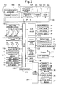
- Fig. 3 is an example of a circuit block diagram to realize the operation of the pachi-slot gaming machine 1 shown in Fig. 1.
- a game control means in this embodiment is made up chiefly of two control circuits.
- a main control circuit 101 controls various peripheral devices electrically connected together, based on input signals transmitted from various detection means.
- a sub-control circuit 201 controls effect images displayed on various liquid crystal display devices and effective sounds emitted from the speakers 5L and 5R, based on game information transmitted from the main control circuit 101 and based on the operational input from the touch panel 28 disposed on the reel display panel 7.
- the main control circuit 101 is comprised of a microcomputer 102, which is a main constituent element of the control circuit 101, disposed on a circuit board and circuits used for random-number sampling.
- the microcomputer 102 includes a ROM 104 in which a game program and data are prestored, a CPU 103 that performs a control operation in accordance with the game program of the ROM 104, and a RAM 105 that provides a work area required for a control process.
- Various means of the present invention are formed by the CPU 103. Processes of various means are executed by allowing the CPU 103 to control the operation of each peripheral device in accordance with the game program.
- a clock pulse generation circuit 106 that generates a reference clock pulse, a frequency divider 107, a random-number generator 108 that generates random numbers, and a sampling circuit 109 that samples random numbers based on signals transmitted from a start lever 13 described later are connected to the CPU 103.
- the microcomputer 102 may perform random-number sampling through software processing. If so, the random-number generator 108 and the sampling circuit 109 can be omitted.
- the ROM 104 of the microcomputer 102 stores a control program to control various operations of the pachi-slot gaming machine.
- the ROM 104 stores a winning probability table used to determine the suitability of a random-number value obtained on the basis of the operation of the start lever 13 in a probability lottery process described later, a stopping table that determines the position where the reels 24L, 24C, and 24R are stopped in response to the operation of the stop buttons 15L, 15C, and 15R, various game information commands issued to the sub-control circuit 201, etc.
- Various peripheral devices are connected to the CPU 103 through an I/O port 110.
- a motor driving circuit 111 drives and controls stepping motors 112L, 112C, and 112R that rotate and drive the reels 24L, 24C, and 24R, respectively, in accordance with a driving signal transmitted from the CPU 103.
- the motor driving circuit 111 stops and controls the stepping motors 112L, 112C, and 112R in accordance with a stopping control signal transmitted from the CPU 103.
- a hopper drive circuit 113 drives and controls a hopper 114, which is a coin payout device, under a payout command issued from the CPU 103.
- a seven-segment drive circuit 122 drives and controls a during-bonus information display part 33, a credit display part 34, and a payout display part 35, which are formed by a seven-segment LED.
- a lamp drive circuit 116 controls lighting of each display part (REPLAY lamp 30, WAIT lamp 31, WIN lamp 32, START lamp 36) that is formed by a lamp.
- the reel-part liquid crystal display device 21, the electronic shutter, and the reel back light are driven and controlled by the sub-control circuit 201.
- the above-mentioned peripherals may instead be configured to be driven and controlled by the main control circuit 101.
- Main input-signal generating means each of which generates an input signal required to allow the microcomputer 102 to generate a control signal to each drive circuit are the start lever 13, the 1-BET switch 8, the 2-BET switch 9, the MAX-BET switch 10, the C/P switch 12, an inserted-coin sensor 117, a reel-stopping signal circuit 118, a reel index detection circuit 115, and a payout detection circuit 119. These are connected to the CPU 103 through the I/O port 110.
- the start lever 13 detects the start operation of a player.
- the inserted-coin sensor 117 detects coins that have passed through a selector that discriminates deformed coins from coins inserted through the coin insertion slot 11.
- the reel-stopping signal circuit 118 detects that each of the stop buttons 15L, 15C, and 15R has been pushed and emits a stop signal.
- the reel index detection circuit 115 receives a signal from a rotation reference position detection switch disposed in the stepping motor and feeds a symbol position reset signal to the CPU 103.
- the payout detection circuit 119 receives a signal from a coin detecting part 120 disposed in the hopper 114 and feeds a payout number signal to the CPU103.
- the random-number generator 108 is generating random numbers that belong to a fixed numerical range from the time when a power switch of the pachi-slot gaming machine 1 is turned on. Effective lines that match the number of coins to be bet are displayed on the reel-part liquid crystal display device 21 when the inserted-coin sensor 117 detects that a player has inserted coins or when the player operates the 1-BET switch 8, the 2-BET switch 9, or the MAX-BET switch 10 under the condition where coins are credited.
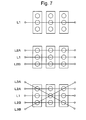
- the bet operation is performed such that, as shown in the enlarged view of Fig.
- a center line L1 functions as an active pay line (hereinafter, referred to simply as "pay line") by a one-bet operation; a top line L2A and a bottom line L2B in addition to the center line L1 function as pay lines by a two-bet operation, and a cross-down line L3A and a cross-up line L3B in addition to the center line L1, the top line L2A, and the bottom line L2B function as pay lines by a three-bet operation.
- pay line active pay line
- random-number values are sampled by the sampling circuit 109 at a timing at which the start lever 13 detects that a player has started a game.
- Sampled random-number values are collated with winning probability tables stored in the ROM 104, and, if a winning coincidence occurs, a winning flag of a corresponding winning combination is set up.
- This lottery process by software is called "probability lottery process," the details of which will be described later.
- Driving pulses are supplied to the stepping motors 112L, 112C, and 112R through the motor driving circuit 111, and the reels 24L, 24C, and 24R start rotating.
- the CPU 103 monitors the driving pulses being supplied, and a "pulse counter" secured by the RAM 105 is updated.
- the value of the pulse counter is monitored, and, when this value becomes equal to a predetermined value, symbols are regarded as having moved by one symbol (also called “one segment"), and a "symbol counter" secured by the RAM 105 increases by one count.
- an index detection signal is emitted whenever the reference symbol passes through the center line L1 of Fig. 7.
- a reset pulse is then input to the CPU 103 through the reel index detection circuit 115.
- the CPU 103 that has detected the input of the reset pulse clears the symbol counter being counted up by the RAM 105 so as to secure the coordination between a symbol position grasped through software and a symbol position displayed actually.
- the CPU 103 stores the code number of a symbol appearing on the center line L1 in a predetermined area of the RAM 105 as a stopping operation position when the CPU 103 receives a stop signal from the reel-stopping signal circuit 118.
- the CPU 103 then refers to a stopping table correlating the stopping operation position with a symbol to be stopped and displayed on the center line L1. Thereafter, the position of the symbol to be stopped that corresponds to the stopping operation position is stored in a predetermined area of RAM 105, and a calculation is performed to obtain the number of pulses (segments) to be supplied so as to stop and display the corresponding symbol. Pulses whose number has been obtained by the calculation are supplied, and stopping control is performed.
- symbol tables stored in the ROM 104 are first collated with the symbol stop position stored in the RAM 105 so as to grasp a situation in which the stop mode of the present game is exhibited.
- the symbol table is formed in correspondence with a train of symbols drawn on the outer circumferential surfaces of the reels 24L, 24C, and 24R.
- the symbol table has a correlation between the code number representing the order of symbols from the reference position and the symbol code formed to correspond to the code number, and serves as a software reel belt.
- the stop mode is collated with winning-symbol combination tables stored in the ROM 104, and a determination is made as to whether a prize is won or not.
- the winning-symbol combination table represents a correlation, for example, between the combination of winning symbols and the number of coins to be paid out when a prize is won, and, according to this, a winning-symbol changing process is performed, for example, in changing a winning symbol combination that becomes effective in accordance with a game situation or changing the number of coins to be paid out.
- the CPU 103 supplies a payout signal to the hopper drive circuit 113 so as to pay out a predetermined number of coins from the hopper 114.
- the coin detecting part 120 counts the number of coins paid out from the hopper 114, and, when the count value reaches a predetermined value, the transmission of a driving signal to the hopper drive circuit 113 is stopped so as to stop the coin payout.
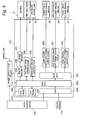
- Fig. 4 is a block diagram showing the structure of the sub-control circuit 201.
- the sub-control circuit 201 controls effect-related peripheral devices, such as the liquid crystal display devices and the speakers 5L and 5R, based on game information transmitted from the main control circuit 101 or based on an input signal transmitted from the touch panel.
- the sub-control circuit 201 includes a sub-microcomputer 202, which is a main constituent element, an upper display panel image control circuit 250 that drives and controls liquid crystal display devices, a reel display panel image control circuit 251, a lower display panel image control circuit 252, a sound source IC 230 that controls a sound emitted from the speakers 5L and 5R, a power amplifier 231 that is used as an amplifier, a reel back lamp control circuit 240, and an electronic shutter control circuit 270 that controls and shuts the reel display panel.
- These control circuits are constituted by a circuit board differing from that of the main control circuit 101.
- the sub-microcomputer 202 includes a sub-CPU 203, a sub-ROM 204 serving as a storage means, and a sub-RAM 205.
- the sub-control circuit 201 of Fig. 5 includes a clock pulse generation circuit, a frequency divider, a random-number generator, and a sampling circuit, which are not shown.
- the sub-ROM 204 stores a communication sequence program with the main control circuit 101, an effect selecting table that selects various effects, etc., based on received game information, and a sound sequence program.
- the sub-RAM 205 is used as a work area to execute these control programs.
- the sub-CPU 203 Based on a command transmitted from the main control circuit 101, the sub-CPU 203 determines the manners of an effect to be controlled by various effect control circuits, and the contents determined by the sub-CPU 203 are transmitted to the effect control circuits.
- the reel back lamp control circuit 240 is used to control the display of an effect, such as a winning effect or the previous notice of a winning flag.
- the electronic shutter control circuit 270 controls the electronic shutter 22 so that the electronic shutter 22 disposed between the reel-part liquid crystal display device 21 and the reels 24L, 24C, 24R generates a visible state or an invisible state based on whether voltage has been applied or not. Based on the contents determined by the sub-microcomputer 202, the electronic shutter control circuit 270 brings a necessary display area into an invisible state so as to shut an area inside the reel-part liquid crystal display device 21 which is specified so as not to be visually discerned by a player.
- the image control circuit is comprised of a plurality of control circuits that control the liquid crystal display devices provided in the respective display panels, i.e., is comprised of the upper display panel image control circuit 250, the reel display panel image control circuit 251, and the lower display panel image control circuit 252.
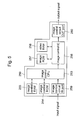
- Fig. 5 is a block diagram of an example of the image control circuits and shows the reel display panel image control circuit 251.
- the reel display panel image control circuit 251 controls an image displayed on the reel-part liquid crystal display device 21 and is comprised of an image control CPU 253, an image control ROM 254, an image control RAM 255, an image ROM 257, a video RAM 258, and an image control IC 256.
- the image control CPU 253 receives parameters determined by the sub-microcomputer 202 through an image control circuit IN port 259 and determines the contents to be displayed on the reel-part liquid crystal display device 21 in accordance with an image control sequence program stored in the image control ROM 254.
- the image control ROM 254 stores a reception sequence program of an image effect command transmitted from the sub-microcomputer 202, an image control sequence program that controls the image control IC 256, etc.
- the image control RAM 255 is used as a work area when the image control program is executed.
- the CPU 103, the sub-CPU 203, and the image control CPU 253 are functionally united together and constitute a controller that controls the reels, the image display devices, and the payout device while executing a predetermined program.
- the image control IC 256 forms an image according to the display contents determined by the image control CPU 253 by use of graphic data stored in the image ROM 257.
- the image is temporarily stored in the video RAM 258 and is outputted to the reel-part liquid crystal display device 21 through an image control circuit OUT port 260 at a proper timing, thus creating a display effect.
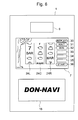
- Fig. 6 is a front view of the pachi-slot gaming machine 1, especially showing the upper display panel 6, the reel display panel 7, and the lower display panel 18.
- a liquid crystal display device that is an electric display device is provided as an image display device in each display part, on which various images are displayed depending on a game situation.
- the reel display panel 7 is in a state in which symbols on the reels 24L, 24C, and 24R can be visually discerned through the reel-part liquid crystal display device 21 and the electronic shutter 22.
- Reel symbols can be visually discerned from the side of a player in this way when the reel-part liquid crystal display device 21 and the electronic shutter 22 are under transparent control (i.e., visible control), but, when an image is displayed on the reel-part liquid crystal display device 21 or when the electronic shutter 22 is subjected to opaque control (i.e., invisible control), the reel symbols cannot be visually discerned.
- transparent control i.e., visible control
- opaque control i.e., invisible control
- the lower display panel 18 includes the lower liquid crystal display device 27, on which a model name and symbols that match the concept of the gaming machine are chiefly displayed. In the figure, the model name "DON-NAVI" is displayed. These images are subjected to image control based on image data stored in the image ROM of the lower display panel image control circuit 252 of the sub-control circuit 201. Therefore, the need to produce a lower display panel for each model or the need to attach a new lower display panel in a manufacturing step does not arise by exchanging the sub-control circuit 201 or the lower display panel image control circuit 252 with another one whenever the model is changed. Therefore, various models can be easily manufactured.
- the upper display panel 6 used as a payout display means includes the upper liquid crystal display device 26, on which a payout table is chiefly displayed.
- the upper display panel 6 is structured so that the amount of media (e.g., number of coins) to be paid out can be changed by a fixed input operation, and the display contents of the payout table can also be changed in accordance with parameters. The details of this will be described later.
- Fig. 8 is an enlarged view of the reels 24L, 24C, and 24R.
- the reel belts 40L, 40C, and 40R of the reels 24L, 24C, and 24R are made of semitransparent films. Symbols, such as "cherry” symbols and “7" symbols, are printed thereon with light-permeable colored ink. The remaining area other than the symbols are masked with opaque ink.
- Lamp casings 41L, 41C, and 41R are provided behind the reel belts 40L, 40C, and 40R so that light emitted from each lamp does not interfere with the area of the symbols.
- Reel back lamps 42L, 42C, and 42R are contained in the rooms of the lamp casings 41L, 41C, and 41R, respectively.
- the reel back lamp control circuit 240 controls and blinks the reel back lamps 42L, 42C, and 42R.
- the reel back lamps 42L, 42C, and 42R for symbols positioned on a pay line are blinked when coins are paid out, or different blinking modes are prepared for each internal-winning combination, and effect displaying is performed when each winning flag is established.
- Fig. 9 is a view planarly expanding the reel belts 40L, 40C, and 40R.
- Each reel has twenty-one symbols.
- Each symbol has numbers 1 to 21 and is stored in the ROM 104 in the form of a symbol table.
- Symbol trains 40L', 40C', and 40R' are moved in order of the symbol number (up from below) in response to the rotation of the reels 24L, 24C, and 24R.
- Fig. 10 is a view showing a payout table that shows the number of media (e.g., coins) to be paid out with respect to a winning symbol combination (i.e., winning combination) in each game situation.
- media e.g., coins
- Internal winning is a state in which sampled random-number values are collated with winning probability tables in the aforementioned probability lottery process, and, as a result, a determination to be "winning” is made, and a winning flag of a corresponding winning combination is set up.
- the winning flag exists, in principle, for each winning combination and is divided chiefly into two in accordance with its characteristic.
- One is a winning flag for a winning combination, called a "small” winning combination, that is relatively small in the number of media to be paid out, that is effective for an effected game, and that is not carried forward to the next game.
- the other one is a winning flag for a winning combination, called a "bonus" winning combination, that is great in the number of media to be paid out and that is carried forward until prize winning is obtained without being used only for an effected game so that the internal lottery probability of a winning combination called a big bonus (BB) or a regular bonus (RB) can increase.
- BB big bonus
- RB regular bonus
- the small winning combination there are a "cherry” winning combination that wins a prize merely when a symbol stops on an pay line of the left reel, a "bell” winning combination that wins a prize when three symbols are stopped and aligned on an pay line, and a "watermelon” winning combination.
- the bonus winning combination there are a regular bonus and a big bonus.
- the regular bonus (RB) is generated, for example, when symbols of "BAR-BAR-BAR" are aligned on an activated pay line. Fifteen coins are first paid out when the prize is won. After that, a one-coin-bet bonus game (called “JAC game” or “winning-combination game”) can be played twelve times or until eight prizes are won.
- the big bonus (BB) is generated, for example, when symbols of "red7-red7-red7" are aligned on an pay line. Fifteen coins are first paid out when the prize is won. After that, during the BB game, a game in which the winning probability of a small winning combination called "general game” or of the RB has increased can be played up to the limit of thirty times.
- the RB game can be played up to three times during the BB game.
- RB-prize winning from a general game is generated, for example, when symbols of "BAR-BAR-BAR" are aligned, but RB-prize winning from a general game during the BB game is generated when symbols of "replay-replay-replay" are aligned.
- the single bonus is generated, for example, when symbols of "7 with sword-7 with sword-7 with sword” are aligned on an pay line. Fifteen coins are first paid out when the prize is won, and then a JAC game can be played once. Although the SB has the name "bonus,” a winning flag is not carried forward. Like the small winning combination, the winning flag is effective only for the present game.
- the game situation is divided chiefly into three situations, based on whether the winning flag of the bonus winning combination exists or not. That is, there are a general game situation in which a bonus winning combination has not yet obtained internal winning, a bonus internal winning situation (also called “bonus internal winning”) in which bonus winning symbols have not yet been aligned on an pay line, and prize winning has not been generated although internal winning is obtained in a probability lottery process, and a bonus game situation (also called “enabled bonus”) in which winning symbols are well aligned on an pay line during bonus internal winning, and a bonus game is being played.
- a bonus internal winning situation also called “bonus internal winning”
- bonus game situation also called “enabled bonus”
- the bonus internal winning is divided into BB internal winning and RB internal winning, based on a bonus kind.
- the "enabled bonus” is also divided into enabled BB and enabled RB.
- a specific state is known concerning a winning probability table of SB during a general game which is called "concentrated machine.”
- a high probability table e.g., SB internal-winning probability 1/2
- a low probability table e.g., SB internal-winning probability 1/20
- a lottery generally, called “plunge lottery”
- a lottery generally, called “blowout lottery”
- the number of coins gradually increases when the high probability table is used.
- the "AT (assist time) function” is known.
- multiple prize patterns that can never be won at the same time are set.
- the winning combinations “bell ⁇ bell - red 7,” “bell ⁇ bell - blue 7,” and “bell ⁇ bell -white 7,” are provided with intervals of four segments or more each being set among the symbols, “red 7,” “blue 7,” and “white 7” on the right reel. Since the kind of internal-winning combination is not notified in an ordinary state, a player does not know which one of the "7"s is to be targeted, and, theoretically, the probability with which a prize is won is only 1/3 after internal winning.
- Replay-replay-replay is a combination of replay winning symbols during a general game and during bonus internal winning, but is a combination of RB winning symbols in a general game during BB and is a combination of winning symbols in a JAC game, according to which fifteen coins are paid out.
- the aforementioned super time is employed as a situation advantageous to a player.
- a super time game can be played.
- a player is notified of information about a stop order required to match-up the combinations of symbols to win a prize. Therefore, prize winning can be reliably generated without an missed winning by allowing the player to operate in accordance with the notified stop order when the SB winning combination or the bell winning combination obtains internal winning.
- it is possible to change the number of media to be paid out with respect to the same winning combination based on the payout table of Fig. 10 by performing a certain input operation.
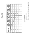
- Fig. 12 is a view showing a winning probability table used for the aforementioned probability lottery process.
- a random-number value is extracted within a range of "0 to 16383," and, when it belongs to a winning range determined for each winning combination, a corresponding winning combination is won internally. For example, when a random-number value extracted in the present game is "10000,” it belongs to a winning range of "2299" to "11024" for a bell winning combination, and a bell winning combination is won internally.
- a random-number value extracted in the present game is "15000,” it belongs to a loss range (i.e., lottery-losing range) of "13669 to 16383,” and each winning combination cannot obtain internal winning and results in a loss.
- a loss range i.e., lottery-losing range
- Fig. 13 is a view showing a game information command table from the main control circuit 101.
- a substrate of the main control circuit 101 that controls a winning determination, coin payout, etc. is different from a substrate of the sub-control circuit 201 that controls the reel-part liquid crystal display device 21, the speakers 5L, 5R, etc. Since game information concerning a state of internal winning or a stopped state of a reel processed by the main control circuit is required for effect control processed by the sub-control circuit 201, both of the substrates are connected together through a straight cable, through which necessary information is transmitted.
- the command to be transmitted there are a "start command” transmitted when a player operates the start lever 13, a “reel stop command” transmitted when the stop buttons 15L, 15C, and 15R are pushed to stop the rotation of the reels 24L, 24C, and 24R, a "one-game end command” transmitted when one game is completely ended, a "parameter change demand command” to allow the machine to execute a parameter changing process, by which the number of media to be paid out and the internal-winning probability can be changed when the power source of the pachi-slot gaming machine 1 is started up, a "keyswitch off command” transmitted when a keyswitch is turned off, and an “initialization command” to allow each liquid crystal display device to display an initial image.
- Fig. 14A to Fig. 14C are a view showing various members that constitute the reel display panel 7.
- Fig. 14A is a front view of the reel display panel 7.
- the reel display panel 7 that is a transparent acrylic plate to which the touch panel 28 is stuck can withstand a physical shock from the outside.
- Fig. 14B is a front view of the picture sheet 20.
- the picture sheet 20 formed by printing pictures with semitransparent ink on a transparent film has a picture of a tree at the left thereof.
- Fig. 14C is a front view of the electronic shutter 22.
- the electronic shutter 22 is made of a liquid crystal film and performs switching between a transparent state and an opaque state depending on voltage to be applied.
- the display area of each lamp part and the seven-segment display part at the right of the electronic shutter is kept transparent, regardless of whether voltage has been applied or not, so as to be always visually discerned by a player.
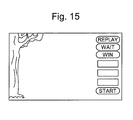
- Fig. 15 is an enlarged view of the reel display panel 7 when the electronic shutter 22 is in an opaque state (i.e., voltage-not-applied state) concerning the overall area.
- this is a display state reached when the power source of the pachi-slot gaming machine 1 is off. In this state, the reel 24 is hidden by the electronic shutter 22 so as not to be visually discerned by the player.
- the picture sheet is disposed in front of the electronic shutter 22 (i.e., on the side of the player), the picture sheet can be visually discerned by the player without being affected by the control state of the electronic shutter 22.
- Each lamp display part and the seven-segment display part at the right of the reel display panel are disposed inner side of the electronic shutter 22. However, since a corresponding display area of the electronic shutter 22 is always in a transparent state, each lamp display part and the seven-segment display part can be visually discerned by the player.
- Fig. 16A to Fig. 16C are views showing an effect screen during a super time game that is in a special game situation.
- Fig. 16A shows the reel display panel 7 prior to a first stopping operation when internal winning of the "bell" is obtained, and table No.5 of the stopping table of Fig. 11 is selected.
- an appropriate stopping operation is recommended by operating the electronic shutter 22 so as to exert transparent control only on a display area of a reel corresponding to a stop button to be stopped and by operating the electronic shutter 22 so as to exert opaque control on the remaining area.
- the stopping table No.5 corresponds to the right stop button of the first stopping operation
- the display area excluding the right reel 24R reaches an opaque state, and only the right reel 24R being rotating can be visually discerned by a player. Accordingly, a recommendation is made that the player should stop the right stop button 15R.
- the term "transparent control" means that the electronic shutter 22 is controlled so that reel symbols positioned behind can reach a discernible state. Therefore, if it falls within a range where reel symbols can be visually discerned by the player, it is permissible to be in a colored state or in a semitransparent state, not in a completely transparent state. Likewise, concerning the opaque state, it is permissible to be in a somewhat semitransparent state if reel symbols positioned behind cannot be visually discerned in greater or lesser degree, without being limited to a state of being optically completely impermeable.
- Fig. 16B is a view showing the reel display panel 7 when the player pushes the right stop button 15R in the state of Fig. 16A. Since the right-stop-button as first-stop-button is a proper stopping operation, the player is notified of the fact that the operation was a proper stopping operation. Notification is realized by allowing only the bell symbols that are an internal-winning combination of symbols to become visually discernible and by allowing the remaining area to become visually indiscernible concerning the display area in which rotating right reel 24R has been visually discerned in Fig. 16A. The display area of the left reel 24L being in an opaque state in Fig. 16A reaches a transparent state, and the rotating left reel 24L can be visually discerned. Accordingly, it is recommended that the player should operate the left reel 24L next.
- Fig. 16C is a view showing the reel display panel 7 when the player pushes the left stop button 24L in the state of Fig. 16B. Since the left-stop-button-second stop is a proper stopping operation, the player is notified of the fact that the operation was a proper stopping operation. Notification is realized by allowing only the bell symbols that are an internal-winning combination of symbols to become visually discernible and by allowing the remaining display area to become visually indiscernible concerning the display area of the rotating left reel 24L has been visually discerned in Fig. 16B. The display area of the center reel 24C being in an opaque state in Fig. 16B reaches a transparent state, and the rotating center reel 24C can be visually discerned. Accordingly, it is recommended that the player should operate the remaining center reel 24C next.
- Fig. 17A is a view showing the reel display panel 7 when a winning combination is realized by properly performing all of the stopping operations during a super time game.
- the electronic shutter part exerts transparent control only on the part of bell symbols that are a winning combination of symbols so that bell symbols on the reel 24 can be visually discerned, and the player is notified of the fact that the "bell" wining combination has won, by displaying the letters "GET" on the reel-part liquid crystal display device 21.
- Fig. 17B is a view showing the reel display panel 7 when a stopping operation during a super time game is improperly performed, so that an missed winning occurs.
- the center stop button 15C is operated by mistake although the left stop button 15L really should be pushed in the state of Fig. 16B.
- the character "x" is largely displayed at the center of the display part, whereby the player is notified of the fact that the operation was an improper operation.
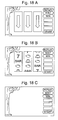
- Fig. 18A to Fig. 18C are views showing a prediction effect screen generated with a predetermined probability after all of the reels 24L, 24C, and 24R are stopped.
- the reels 24L, 24C, and 24R rotating are first displayed through the display panel 7 (Fig. 18A), and then all of the reels are stopped after a stopping operation by player (Fig. 18B)).
- the electronic shutter 22 reaches an opaque state, and the reels 24L, 24C, and 24R are hidden behind the electronic shutter as shown in Fig. 18C.
- a prediction effect based on a internal-winning combination in the present game is executed.
- the prediction effect of this embodiment has contents that exhibit the reliability of the generation of a bonus winning combination, depending on the degree of coincidence between the display positions of bell symbols displayed on the reel-part liquid crystal display device 21 and the stopped positions of bell symbols of the reels 24L, 24C, and 24R that have been stopped and displayed.
- Fig. 21A is a view showing a prediction effect generation table. If BB, RB, "watermelon,” and SB obtain internal winning in a probability lottery process, reference is made to the prediction effect generation table when a lottery is operated as to whether a prediction effect is to be executed or not.
- Fig. 21B is a view showing an effect-kind selection table. If the generation of the prediction effect is determined by the prediction effect generation table, reference is made to the effect-kind selection table to determine the contents of the effect. The effect is divided based on the accuracy with which a coincidence is created between the stopped positions of bell symbols of the reels 24L, 24C, and 24R and the stopped positions of bell symbols of the reel-part liquid crystal display device 21. The probability that a bonus winning combination will be won internally is high proportionately with the greatness of degree of the coincidence.
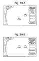
- Fig. 19A and Fig. 19B are views showing a concrete example of the prediction effect mode.
- Fig. 19A is a view that is displayed when one is selected among "Appearance number-2," “Appearance number-3,” “Appearance number-4" and “Appearance number-5" of the effect-kind selection table of Fig. 21B when the reels 24L, 24C, and 24R are stopped in the display mode of Fig. 18B.
- the reel stop mode of Fig. 18B on the reels, bell symbols are displayed on the middle part of the center reel 24C and the upper part of the right reel 24R, but, on the reel-part liquid crystal display device 21, bell symbols are displayed on the lower part of the center reel and the middle part of the right reel. From this, it is understood that the prediction effect is low in reliability so that the display positions of the both-side symbols do not coincide with each other.
- Fig. 19B is a view that is displayed when the reels 24L, 24C, and 24R are stopped in the display mode of Fig. 18B and when one of the kinds of "Appearance number-1" is selected in the effect-kind selection table of Fig. 21B.
- bell symbols are displayed on the middle part of the center reel 24C and the upper part of the right reel 24R
- bell symbols are displayed on the middle part of the center reel and the middle part of the right reel.
- Concerning the display position the right reel 24R is in the state of non-coincidence, but the center reel 24C is in the state of coincidence. From this, it is understood that the prediction effect is high in reliability.
- Fig. 20 is a view showing a BR generation and BR continuation number lottery table.
- generation of a BR and a BR continuation number are settled by performing a lottery with a fixed probability when a predetermined winning combination is internally won.
- BR is generated with a probability of 16/128 at the "watermelon" internal winning, with a probability of 11/128 at the two-cherry internal winning, and with a probability of 25/128 at the loss.
- Fig. 22A is a views showing a support menu used to allow a hole clerk as a game manager to change or select the payout rate as an amount of payout of the pachi-slot gaming machine 1.
- a support menu screen is displayed when the electric power source of the pachi-slot gaming machine 1 is applied in a state in which a keyswitch (not shown) provided in the power supply unit disposed in the pachi-slot gaming machine is on.
- the support menu is comprised of three modes. Mode 1 is a mode used to change the number of coins to be paid out and the internal-winning probability for each winning combination, in which an arbitrary performance is selected from a payout-rate setting screen described later.
- Mode 2 is a mode used to change the number of coins to be paid out and the generation probability of a super time game for each winning combination.
- Mode 3 is a mode used to perform six-grade setting. One of the modes can be selected by touching each display area. When the setting is finished, "End" is selected to return to an ordinary game situation.
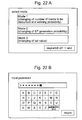
- Fig. 22B is a view showing a password input screen displayed when Mode 1 is selected.
- Mode 1 is a mode used to change the payout rate by changing the internal-winning probability of a winning combination of the pachi-slot gaming machine 1 and the number of media to be paid out.
- a password is required to be inputted when changed to a setting screen. For, example, a specified password is inputted through an character input means formed by the touch panel 28 displayed on the lower center part of the screen. After the password is inputted, an "End" command of the character input means is inputted, and the password is collated. If the password is correctly inputted, the screen is changed to the setting screen. In order to end the input operation, "Return" is selected to return to a support menu screen.
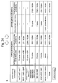
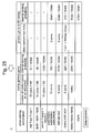
- Fig. 23 to Fig. 25 are each a view showing a payout-rate setting screen.
- a plurality of payout-rate setting screens are prepared, and the number of coins as the amount of media to be paid out and the internal-winning probability are determined depending on each winning combination.
- Fig. 23 is a view showing a payout-rate setting screen A displayed after a password is inputted on a password input screen.
- the setting screen A can set a standard payout rate.
- the internal-winning probability and the number of media to be paid out during a general game and in a general game during BB are set in accordance with the winning symbol combination of each winning combination listed at the left of the screen.
- the internal-winning probability is 141/16384, and the number of media to be paid out when the winning combination is realized is three.
- a screen-changing icon is displayed at the upper center of the screen. The present display screen can be changed to a next screen by touching the icon. If a screen is to be intentionally used, a determination is made by touching a "Determine" icon at the lower left of the screen, thus returning to a support menu screen of Fig. 22(a).
- Fig. 24 is a view showing a payout-rate setting screen B.
- the number of coins as the amount of media to be paid out and the internal-winning probability of a small winning combination in a general game situation is increased (e.g., in the general game situation, the internal-winning probability of "watermelon” is 356/16384, the number of coins to be paid out is 15; the internal-winning probability of "bell” is 7688/16384, the number of coins to be paid out is 6), whereby coin holding during the general is improved.
- the internal-winning probability of "BB” is set at 38/16384, and the payout rate in total is set to be converged into a fixed value.
- Fig. 25 is a view showing a payout-rate setting screen C.
- the setting screen C the internal-winning probability of "bell" during a general game is increased, thereby player's coins are not spoiled easily.
- the number of RB games playable during BB is lessened from three to two, and the payout rate in total is set to be converged into a fixed value.
- the characteristic of the game can be changed by selecting one from among the plurality of kinds of payout-rate setting screens in this way, and, in order to further adjust the details of the characteristic of the game, the structure can be formed so that each value in the payout-rate setting screen can be changed.
- Fig. 26A and Fig. 26B are views showing a payout table displayed on the upper display panel 6.
- the structure is formed so that the number of media to be paid out and the internal-winning probability with respect to each winning combination can be changed as mentioned above, and the payout table is controlled and displayed in accordance with set parameters.
- Fig. 26A is a view showing a payout table displayed when setting is performed in accordance with the contents of the payout-rate setting screen A shown in Fig. 23.
- Fig. 26B is a view showing a payout table displayed when setting is performed in accordance with the contents of the payout-rate setting screen B shown in Fig. 24. From this, it is understood that, for example, the number of media to be paid out for "watermelon” during a general game is changed from “3" to "15,” and the number of media to be paid out for "cherry” is changed from “1" to “2,” in comparison with the payout table shown in Fig. 26A.
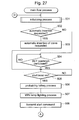
- step 501 the CPU 103 performs an initializing process before a game is started (step 501; hereinafter, "step” is abbreviated as "S").
- step 501 the initializing process is performed to change the amount of media (e.g., the number of coins) to be paid out and the internal probability. The details of this will be described later.
- the CPU 103 determines whether coins have been required to be automatically inserted, i.e., whether a "replay" prize was won in the last game (S502). If determined as “YES,” coins required to be inserted are automatically inserted (S503), and the step shifts to the process of S505. If determined as "NO” in S502, a determination is made as to whether coins have been newly inserted, i.e., whether input has been performed from the inserted-coin sensor 117 caused by a player inserting coins through the coin insertion slot 11 and the input caused by operating the BET switches 8, 9, 10 (S504). If determined as "YES " in S504, the step shifts to S505, and, if determined as "NO,” an input signal continues to be monitored until a BET operation is performed.
- the CPU 103 determines whether input has been performed by operating the start lever 13 (S505). If determined as “YES,” the step shifts to S506, and, if determined as "NO,” an input signal continues to be monitored until the start lever 13 is operated.
- a probability lottery process is performed (S506).
- a random-number value for a lottery is first extracted within the range of "0 to 16383 " by use of the random-number generator 108 and the sampling circuit 109.
- a determination is made as to a winning range to which an extracted random-number value belongs, and a corresponding internal-winning combination (i.e., winning flag) is determined by use of the winning probability table (Fig. 12) that sets a random-number-value range (i.e., winning range) in which a prize is won in accordance with a game situation and the number of inserted medals.
- the function of a lottery means is realized by the process of S506.
- the WIN lamp lighting process is a process in which a determination and execution are made as to whether the WIN lamp 32 that lights with a fixed probability is lit when a bonus winning combination has obtained internal winning.
- the game information of the main control circuit 101 at the start of a game is transmitted to the sub-control circuit (S508).
- commands to be transmitted there are a winning flag determined by the aforementioned probability lottery process and a stopping table number determined in accordance with the present game situation and a winning flag, as shown in "Start command" of the game information command of Fig. 13.
- a predetermined period of time e.g., 4.1 seconds
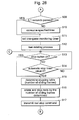
- the CPU 103 controls the motor driving circuit 111 and performs a process (reel-rotating process) to rotate the reels 24L, 24C, and 24R (S512).
- the reel-rotating process is performed such that an acceleration process is performed from a state in which the reels 24L, 24C, and 24R are being stopped, and, after each of the reels reaches a certain speed, a constant-rotation process is performed. Under the condition where the reels have reached the constant-rotation state, the stop buttons 15L, 15C, and 15R are made effective so that the reels 24L, 24C, and 24R can be operated and stopped.
- the CPU 103 determines whether any one of the stop buttons 15L, 15C and 15R has been operated (whether the stop button is on), i.e., determines the presence or absence of a stop signal sent from the reel-stopping signal circuit 118 when a player operates the stop buttons 15L, 15C, and 15R (S513). If determined as "YES,” the step proceeds to S515, and, if determined as "NO,” the step proceeds to S514.
- the automatic stop process is to perform automatic stopping control even if the reels 24L, 24C, and 24R are rotating without operating the stop buttons 15L, 15C, and 15R when a fixed period of time (e.g., 40 seconds) passes since the reels start rotating. If determined as "YES,” i.e., if the automatic stop timer is "0,” the step proceeds to S515 to automatically stop the reels, and, if determined as "NO,” the step proceeds to S513 to continue monitoring the reception of the stopping operation.
- the CPU 103 performs "sliding-segment-number determining process.”
- the number of sliding segments of the reel is determined corresponding to the stop button subjected to a stopping operation.
- the term “sliding-segment-number” denotes the number of symbols (segments) to be slid from the position (designated as “stopping operation position") of a symbol displayed on each display window 43L, 43C, 43R when the stop buttons 15L, 15C, and 15R have been operated, and the reel is stopped when the number of symbols to be slid is reached (the position where the reel is actually stopped is designated as "stop position").
- the CPU 103 controls the motor driving circuit 111 so that the reel corresponding to the stop button subjected to a stop operation is rotated and stopped when a predetermined sliding-segment-number is reached (S516).
- the function of the stopping control means is realized by the processes of S515 and S516.
- the CPU 103 transmits a "reel stop command” showing that the reel has been stopped to the sub-control circuit 201 (S517).
- the reel stop command transmits a stop order status (What is the order of the present stopping operation?) and a stop reel status (Which one of the reels has been stopped?) to the sub-control circuit 201.
- the CPU 103 determines whether all reels have been stopped. If determined as "YES,” the step proceeds to S519, and, if determined as "NO,” the step proceeds to S513 since a rotating reel still remains.
- the CPU 103 performs a winning retrieval process (S519).
- a winning retrieval process a determination is made as to whether the stop mode of a symbol shows that a prize has been won. If the stop mode shows a winning condition, a prize winning flag of the corresponding winning combination is stored in the RAM 105.
- a determination is formed by collating the code number of a symbol on the center line L1 with a winning-symbol combination table stored in the ROM 104.
- a shifting process is performed if a game situation is changed because of the end of the present game (S523). For example, there are a case in which it is the final prize winning of a bonus game, a case in which a bonus wins internally during the present game, and a case in which symbols of "7-7-7" are stopped on an pay line and a bonus game starts.
- Fig. 30 is a flowchart showing the initializing process.
- the CPU 103 first performs all clear of the RAM 105 (S530), and then determines whether the keyswitch is on (S531).
- the keyswitch is a switch that selects whether to execute the parameter changing process in which the number of media to be paid out is changed or the internal-winning probability is changed. If the power source is started up in a state in which the keyswitch is on, the parameter changing process as a payout changing process executed by the sub-control circuit 201 is performed, and, if the power source is started up in a state in which the keyswitch is off, the initialization of the game start is performed without executing the parameter changing process.
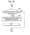
- a parameter changing demand command is first transmitted to the sub-control circuit 201 in order to perform the parameter changing process (S532). Thereafter, a determination is made as to whether the keyswitch has been subjected to an off operation (S533), and, if determined as "NO,” an initialization command is transmitted (S537) so as to return to the main process. If determined as "YES” in S533, a keyswitch off command is transmitted to the sub-control circuit 201 to end the parameter changing process (S534).
- S534 is skipped if determined as "NO.” Thereafter, a determination is made as to whether a parameter change completion command, which shows that the parameter changing process has been ended on the side of the sub-control circuit, has been received or not. If determined as "YES,” a rewriting process of the number of media to be paid out or the winning probability is executed based on the contents of the reception command (S536), and an initialization command is transmitted (S537) so as to return to the main flow. If determined as "NO,” the reception of the command is monitored in S535 because the changing operation is still being performed.
- Fig. 31 is a flowchart showing an interrupt process 1.
- the interrupt process 1 is executed by an interruption every 3mS, and a command transmitted from the main control circuit 101 is stored in the sub-RAM 205.
- the sub-CPU 203 first checks an input buffer (S600), and determines whether the input buffer has an input signal (S601). If determined as “NO,” the process is ended. If determined as "YES,” the reception flag is turned on (S602), and the contents of a reception command are set in the sub-RAM 205 (S603), and the process is ended. Thereafter, the reception command is checked, and a determination is made as to whether the reception command is an initialization command (S604). If determined as "YES,” the applied payout rate setting and the image data based thereon are checked (S605), and an image is displayed on each liquid crystal display device (S606), and the process is ended. If determined as "NO,” the process is ended.
- Fig. 32 is a flowchart showing the main process on the side of the sub-control circuit 201.
- the sub-CPU 203 first checks the reception flag of the sub-RAM 205 and determines whether a parameter change demand command has been transmitted from the main control circuit 101 (S620). If determined as "YES,” the parameter changing process is executed (S621), and the step proceeds to S622. If determined as "NO,” S621 is skipped.
- the parameter changing process is executed to change the number of media to be paid out or the probability. The details will be described later.
- the effect control process at the reel stop is to perform a notification of a BR generation lottery process or a stop order in the lasting BR and to perform an effect in accordance with consistency between the contents of the notification and an actual stopping operation. The details of this will be described later.
- S626 a determination is made as to whether a one-game end command has been received or not (S626). If determined as "NO,” S627 is skipped to return to the process of S620, and the same process is repeatedly operated. If determined as "YES,” an effect control process for the time when one game is ended is executed (S627).
- the effect control process for the time when one game is ended is to perform a prediction effect process or an updating process of a BR continuation number when BR is lasting. The details will be described later.
- the main process of the sub-control circuit 201 is to repeatedly perform a process for branching into corresponding effect processes based on a command transmitted from the main control circuit 101 in this way.
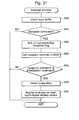
- Fig. 33 is a flowchart showing the parameter changing process.
- the CPU 103 first displays the support menu screen of Fig. 22A (S540). In the support menu, any one of the three modes can be selected.
- the sub-CPU 203 first determines whether Mode 1 has been selected (S541). If determined as "YES,” a payout/probability changing process is executed (S542), and the step proceeds to S547. If determined as "NO,” a determination is made as to whether Mode 2 has been next selected (S543). If determined as "YES,” a super-time-generation probability changing process is executed (S544), and the step proceeds to S547.
- Mode 3 has been next selected (S545), and if determined as "YES,” a setting change process is executed, and the step proceeds to S547. If determined as "NO,” no mode is executed, and the step proceeds to S547.
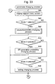
- Fig. 35 is a flowchart showing the payout/probability changing process.
- the CPU 103 first displays the password input screen of Fig. 22B (S550). Thereafter, a determination is made as to whether characters have been inputted by use of a pseudo-keyboard displayed on the screen (S551). If determined as "YES,” a corresponding input character is displayed on an input-character display part of Fig. 22B (herein, the character is displayed as a blank character) (S552), and the step returns to S551. If determined as "NO,” a determination is made as to whether a correction at the lower right of the pseudo-keyboard has been made after that (S553). If determined as "YES,” a character inputted last time is deleted (S554), and the step returns to S551.
- Fig. 37 is a flowchart showing the input process.
- the CPU 103 first displays the payout setting screen A of Fig. 23 as an initialization screen (S560).
- the payout setting screen A is one of a plurality of pieces of preset payout and provability data and shows a winning combination, the number of media to be paid out, and probability of internal winning corresponding with this combination. Thereafter, a determination is made as to whether the screen changing button at the upper part of the payout-rate setting screen has been operated (S561). If determined as "YES," a payout-rate setting screen that is another kind of payout and provability data corresponding to an input operation is displayed (S562), and the step returns to S561.
- the process of the authentication means that authenticates the effectiveness of a password to be inputted is realized by the steps of S550 to S559 among the processes of the payout changing means.
- a change in the amount of media to be paid out by the payout changing means is determined in accordance with a result of the authentication of this authentication means.
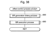
- Fig. 38 is a flowchart showing the effect control process at the start.
- the sub-CPU 203 first performs a BR generation lottery process (S660).
- the BR generation lottery process is a process to determine whether a battle rush that is a special game is generated. The details of this will be described later.
- a BR execution process is performed (S680). The BR execution process is to make a stop order notification while BR is lasting. The details of this will be described later.
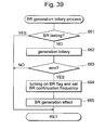
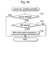
- Fig. 39 is a flowchart showing the BR generation lottery process.
- the sub-CPU 203 first checks the BR flag stored in the sub-RAM 205, and determines whether a BR game is being played at present (S661). If determined as “YES,” the step returns to the effect control process at the start. If determined as "NO,” a determination is made as to whether any one of the BR continuation frequencies has been won (S662, 663) with reference to the BR generation/BR continuation number lottery table of Fig. 20. If determined as "NO” (loss), the step returns to the effect control process at the start. If determined as "YES,” the BR flag of the sub-RAM 205 is turned on, and the continuation number that has won the BR continuation number is set (S664). Thereafter, the BR generation effect is performed (S665), and the step returns to the effect control process at the start.
- Fig. 40 is a flowchart showing the BR execution process.
- the sub-CPU 203 first checks the BR flag and the BR withdrawal flag stored in the sub-RAM 205, and determines whether BR is lasting at present or whether BR is being temporarily stopped because a bonus is generated during BR (S681 ). If determined as "NO,” the step returns to the effect control process at the start as it is, because BR is not lasting. If determined as "YES,” a next determination is made as to whether, by checking the reception flag of the sub-RAM 205, a bonus winning combination has been internally won (S682).
- BR is stopped, and, in order to complete the bonus game, the BR flag of the sub-RAM 205 is turned off, and the BR withdrawal flag is turned on (S683), and the step returns to the effect control process at the start.
- the BR withdrawal flag of the sub-RAM 205 is turned off, and the BR flag is turned on (S684). Thereafter, in order to check whether all of the BR continuation number have been used, the BR continuation number of the sub-RAM 205 is checked, and a determination is made as to whether the continuation number reaches 0 (zero) (S685). If determined as "YES,” the BR flag is turned off from the fact that BR has been ended (S686), and the step returns to the effect control process at the start.
- the reception flag of the sub-RAM 205 is then checked from the fact that a regular number of BR games have not yet completed, and a determination is made as to whether bell or SB has been internally won during the present game (S687). If determined as "YES,” an appropriate stop order is notified with reference to a selected stopping-table kind stored in the reception flag of the sub-RAM 205 (S688), and the step returns to the effect control process at the start. If determined as "NO,” the step returns to the effect control process at the start without any notification.
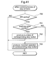
- Fig. 41 is a flowchart showing the effect control process performed when the reels are stopped.
- the sub-CPU 203 first checks the BR flag of the sub-RAM 205, and determines whether BR is lasting at present (S700). If determined as "NO,” the step returns to the sub-side main process as it is. If determined as "YES,” a stop command of the reception flag of the sub-RAM 205 is then checked, and stop-order data and stop-reel data are collated with to-be-used table No.
- Fig. 42 is a flowchart showing the effect control process performed when one game is ended.
- the sub-CPU 203 first executes a prediction effect generation process that determines whether the prediction effect of an internal-winning combination is generated (S720). Thereafter, when the present game situation is in the state of BR, a parameter updating process by which related parameters are updated is executed (S740). Thereafter, when the generation of the prediction effect is determined by the prediction effect generation process, the effect process is executed (S760), and the step returns to the sub-side main process.
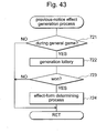
- Fig. 43 is a flowchart showing the prediction effect generation process.
- the sub-CPU 203 first checks the reception flag of the sub-RAM 205, and determines whether the present game situation is during a general game (S721). If determined as "YES,” a generation lottery of the prediction effect is operated with reference to the prediction effect generation table of Fig. 21A (S722). Thereafter, a determination is made as to whether a prize has been won (S723). If determined as "YES,” an effect-form determining process that determines the form of the prediction effect is executed with reference to the effect-kind selection table of Fig. 21B (S724), and the step returns to the effect control process performed when one game is ended. If determined as "NO,” the step directly returns to the effect control process performed when one game is ended.
- Fig. 44 is a flowchart showing the parameter updating process.
- the sub-CPU 203 first checks the one-game end command of the reception flag stored in the sub-RAM 205, and determines whether the present game situation is during a bonus game(S741). If determined as "YES,” the step directly returns to the effect control process of the one-game end, because BR is never lasting. If determined as "NO,” the BR flag stored in the sub-RAM 205 is then checked, and a determination is made as to whether BR is lasting at present (S742). If determined as "NO,” the step directly returns to the effect control process of the one-game end. If determined as "YES,” the BR continuation number counter of the sub-RAM 205 is subjected to a subtraction operation (S743), and the step returns to the effect control process of the one-game end.
- the present invention is applicable to a gaming machine using various type of game medium, for example a token, coupon, magnetic card storing gaming data and combination thereof.
- the present invention is applicable to a slot machine which does not have stop buttons
- the stopping control means of the slot machine is performed in the CPU and control circuit by measuring timing for reel stopping.
- the present invention is applicable also to a pachinko gaming machine including an electric display device, to an arcade gaming machine, and to a domestic game in which the aforementioned functions are performed on software in a pseudo manner.
- the aforementioned structure it is possible to solve the problem of dead stock resulting from the fact that a physical acrylic plate and a symbol cell sheet are used in a display panel and the problem of an increase in the number of assembly steps. Further, since the structure is formed such that the amount of payout for a winning combination can be changed afterward, a flexible change in accordance with the business policy of a center can be made.
Abstract
Description
Claims (8)
- A gaming machine comprising:a plurality of reels for variably displaying each of a plurality of symbols thereon;an image display device for displaying an image that differs from the symbols of the reels;a payout device for payout;a controller for executing a predetermined program and controls the reels, the image display device, and the payout device,wherein the controller operates a lottery of a winning combination according to the predetermined program;the controller controls and stops a changing display of the reel based on the winning combination obtained by the lottery;the controller allows the payout on the basis of an amount of payout set to the winning combination when a stop mode of the reel matches a symbol combination of the winning combination; andthe controller allows the image display device to display the winning combination and an amount of payout while changing the amount of payout.
- The gaming machine according to claim 1, wherein the image display device is formed by an electric display device and displays an image with reference to the amount of payout.
- The gaming machine according to claims 1 or 2, wherein the controller operates in a plurality of operating modes for changing the amount of payout.
- The gaming machine according to claim 3, wherein at least one of the operating modes changes a probability of the lottery.
- The gaming machine according to claims 3 or 4, wherein at least one of the operating modes changes the probability of the lottery for a bonus winning combination.
- The gaming machine according to any one of claims 1 to 5, wherein the controller has a plurality of kinds of payout data, and applies one kind of the payout data based on a selecting operation of a manager for managing the gaming machine.
- The gaming machine according to any one of claims 1 to 6, wherein the controller also authenticates effectiveness of a password inputted by an operation of a manager for managing the gaming machine, and changing the amount of payout on the basis of a result of the authentication means.
- A gaming machine comprising:variable display means for variably displaying a plurality of symbols;lottery means for operating a lottery of a winning combination;stopping control means for controlling and stopping the variable display means on a basis of a result of the lottery;payout means for payout on the basis of an amount of the payout set for the winning combination when a stopped state of the variable display means reaches a symbol combination equal to the winning combination;payout display means for displaying the winning combination and at least the amount of payout to be paid out; andpayout changing means for changing the amount of payout.
Applications Claiming Priority (2)
| Application Number | Priority Date | Filing Date | Title |
|---|---|---|---|
| JP2002335011A JP2004166880A (en) | 2002-11-19 | 2002-11-19 | Game machine |
| JP2002335011 | 2002-11-19 |
Publications (3)
| Publication Number | Publication Date |
|---|---|
| EP1424663A2 true EP1424663A2 (en) | 2004-06-02 |
| EP1424663A3 EP1424663A3 (en) | 2005-09-07 |
| EP1424663B1 EP1424663B1 (en) | 2008-07-16 |
Family
ID=32290334
Family Applications (1)
| Application Number | Title | Priority Date | Filing Date |
|---|---|---|---|
| EP03026651A Expired - Lifetime EP1424663B1 (en) | 2002-11-19 | 2003-11-19 | Gaming Machine |
Country Status (9)
| Country | Link |
|---|---|
| US (1) | US20040152502A1 (en) |
| EP (1) | EP1424663B1 (en) |
| JP (1) | JP2004166880A (en) |
| AT (1) | ATE401636T1 (en) |
| AU (1) | AU2003262345B2 (en) |
| DE (1) | DE60322172D1 (en) |
| ES (1) | ES2307859T3 (en) |
| PT (1) | PT1424663E (en) |
| ZA (1) | ZA200308998B (en) |
Cited By (3)
| Publication number | Priority date | Publication date | Assignee | Title |
|---|---|---|---|---|
| EP1603090A2 (en) * | 2004-06-04 | 2005-12-07 | Aruze Corp. | Gaming machine |
| EP1622104A3 (en) * | 2004-07-27 | 2006-12-20 | Aruze Corp. | Gaming machine, service providing system, server and mobile device |
| US10460552B2 (en) | 2015-08-20 | 2019-10-29 | Bally Gaming, Inc. | Edge-lit reels for wagering gaming machines |
Families Citing this family (38)
| Publication number | Priority date | Publication date | Assignee | Title |
|---|---|---|---|---|
| US8490973B2 (en) | 2004-10-04 | 2013-07-23 | Shfl Entertainment, Inc. | Card reading shoe with card stop feature and systems utilizing the same |
| US8511684B2 (en) | 2004-10-04 | 2013-08-20 | Shfl Entertainment, Inc. | Card-reading shoe with inventory correction feature and methods of correcting inventory |
| US7510475B2 (en) | 2001-05-22 | 2009-03-31 | Wms Gaming, Inc. | Gaming machine with superimposed display image |
| US6517433B2 (en) * | 2001-05-22 | 2003-02-11 | Wms Gaming Inc. | Reel spinning slot machine with superimposed video image |
| US7708640B2 (en) * | 2002-02-15 | 2010-05-04 | Wms Gaming Inc. | Gaming machine having a persistence-of-vision display |
| US9064372B2 (en) | 2002-02-15 | 2015-06-23 | Wms Gaming Inc. | Wagering game with simulated mechanical reels having an overlying image display |
| JP2004166820A (en) | 2002-11-18 | 2004-06-17 | Aruze Corp | Game machine |
| US7972206B2 (en) | 2002-11-20 | 2011-07-05 | Wms Gaming Inc. | Gaming machine and display device therefor |
| JP2004166962A (en) | 2002-11-20 | 2004-06-17 | Aruze Corp | Game machine |
| JP2004166963A (en) | 2002-11-20 | 2004-06-17 | Aruze Corp | Game machine |
| US8096867B2 (en) | 2002-11-20 | 2012-01-17 | Universal Entertainment Corporation | Gaming machine and display device with fail-tolerant image displaying |
| US8118674B2 (en) * | 2003-03-27 | 2012-02-21 | Wms Gaming Inc. | Gaming machine having a 3D display |
| US7892094B2 (en) | 2003-05-14 | 2011-02-22 | Universal Entertainment Corporation | Gaming machine with a light guiding plate subjected to a light scattering process and having a light deflection pattern |
| US7219893B2 (en) * | 2003-05-14 | 2007-05-22 | Aruze Corporation | Gaming machine |
| US7434805B2 (en) * | 2003-07-17 | 2008-10-14 | Shuffle Master, Inc | Intelligent baccarat shoe |
| US7029009B2 (en) | 2003-07-17 | 2006-04-18 | Shuffle Master, Inc. | Playing card dealing shoe with automated internal card feeding and card reading |
| JP2006247196A (en) * | 2005-03-11 | 2006-09-21 | Aruze Corp | Game management system |
| JP2006304970A (en) * | 2005-04-27 | 2006-11-09 | Aruze Corp | Game machine |
| JP2006304971A (en) * | 2005-04-27 | 2006-11-09 | Aruze Corp | Game machine |
| US20090131145A1 (en) | 2005-06-30 | 2009-05-21 | Aoki Dion K | Wagering Game with Overlying Transmissive Display for Providing Enhanced Game Features |
| WO2007078752A2 (en) | 2005-12-19 | 2007-07-12 | Wms Gaming Inc. | Multigame gaming machine with transmissive display |
| JP4816912B2 (en) * | 2006-02-10 | 2011-11-16 | 大日精化工業株式会社 | Optical flip-flop circuit |
| US20070206713A1 (en) * | 2006-02-23 | 2007-09-06 | Aruze Corp. | Gaming machine |
| US8403743B2 (en) * | 2006-06-30 | 2013-03-26 | Wms Gaming Inc. | Wagering game with simulated mechanical reels |
| US8128477B2 (en) | 2006-06-30 | 2012-03-06 | Wms Gaming, Inc. | Wagering game with simulated mechanical reels |
| JP2008017945A (en) | 2006-07-11 | 2008-01-31 | Aruze Corp | Game machine, and game controlling method |
| US9449454B2 (en) * | 2006-11-02 | 2016-09-20 | Bally Gaming, Inc. | Wagering game having bonus-award feature with changing state |
| JP2008178519A (en) * | 2007-01-24 | 2008-08-07 | Aruze Corp | Game machine |
| WO2009009058A2 (en) | 2007-07-11 | 2009-01-15 | Wms Gaming Inc. | Wagering game having display arrangement formed by an image conduit |
| AU2008207356A1 (en) * | 2007-08-28 | 2009-03-19 | Aristocrat Technologies Australia Pty Limited | Gaming system, a game controller, a player interface, and a method of gaming |
| AU2008207690C1 (en) | 2007-09-12 | 2016-04-21 | Aristocrat Technologies Australia Pty Limited | A gaming system and a method of gaming |
| US9076301B2 (en) * | 2007-09-24 | 2015-07-07 | Aruze Gaming America, Inc. | Gaming machine displaying predetermined images for displaying a bonus symbol at a predetermined position |
| WO2009059138A1 (en) | 2007-11-01 | 2009-05-07 | Wms Gaming Inc. | Wagering game apparatus and method to provide a trusted gaming environment |
| KR101499546B1 (en) * | 2008-01-17 | 2015-03-09 | 삼성전자주식회사 | Method and apparatus for controlling display area in touch screen device, and computer readable medium thereof |
| US8172666B2 (en) | 2008-04-01 | 2012-05-08 | Aruze Gaming America, Inc. | Slot machine |
| JP2015217074A (en) * | 2014-05-16 | 2015-12-07 | 株式会社ユニバーサルエンターテインメント | Gaming machine |
| US10638618B1 (en) * | 2016-07-12 | 2020-04-28 | Apple Inc. | Cosmetic integration of displays |
| US11127245B2 (en) * | 2018-10-03 | 2021-09-21 | Sg Gaming, Inc. | Compact game display system with virtual depth augmentation |
Citations (8)
| Publication number | Priority date | Publication date | Assignee | Title |
|---|---|---|---|---|
| WO1999053454A1 (en) * | 1998-04-13 | 1999-10-21 | Game Data, Inc. | Casino game with combination display |
| US6068552A (en) * | 1998-03-31 | 2000-05-30 | Walker Digital, Llc | Gaming device and method of operation thereof |
| EP1063622A2 (en) * | 1999-06-23 | 2000-12-27 | Wms Gaming, Inc. | Gaming machine with multiple payoff modes and award presentation schemes |
| US6241607B1 (en) * | 1998-09-16 | 2001-06-05 | Silicon Gaming-Nevada | Non-rectangular and/or non-orthogonal arrangement of gambling elements in a gaming apparatus |
| WO2001074464A1 (en) * | 2000-03-31 | 2001-10-11 | Wms Gaming Inc. | Gaming machine with player selected events |
| US20010031658A1 (en) * | 2000-02-28 | 2001-10-18 | Masaaki Ozaki | Pattern display device and game machine including the same |
| WO2002089935A1 (en) * | 2001-04-11 | 2002-11-14 | Walker Digital, Llc | Method and apparatus for remotely customizing a gaming device |
| EP1260928A2 (en) * | 2001-05-22 | 2002-11-27 | WMS Gaming Inc | Reel spinning slot machine with superimposed video image |
Family Cites Families (8)
| Publication number | Priority date | Publication date | Assignee | Title |
|---|---|---|---|---|
| US6315666B1 (en) * | 1997-08-08 | 2001-11-13 | International Game Technology | Gaming machines having secondary display for providing video content |
| US6135884A (en) * | 1997-08-08 | 2000-10-24 | International Game Technology | Gaming machine having secondary display for providing video content |
| US6264561B1 (en) * | 1998-10-01 | 2001-07-24 | International Game Technology | Electronic game licensing apparatus and method |
| US6468156B1 (en) * | 1999-03-08 | 2002-10-22 | Igt | Maximum bonus pay schedule method and apparatus for a gaming machine |
| US6350199B1 (en) * | 1999-03-16 | 2002-02-26 | International Game Technology | Interactive gaming machine and method with customized game screen presentation |
| US6802778B1 (en) * | 1999-09-13 | 2004-10-12 | Igt | Gaming apparatus and method with operator-configurable paytables |
| US7338372B2 (en) * | 2001-09-28 | 2008-03-04 | Bally Gaming International, Inc. | Reconfigurable gaming machine |
| JP2004166879A (en) * | 2002-11-19 | 2004-06-17 | Aruze Corp | Game machine |
-
2002
- 2002-11-19 JP JP2002335011A patent/JP2004166880A/en not_active Withdrawn
-
2003
- 2003-11-19 ES ES03026651T patent/ES2307859T3/en not_active Expired - Lifetime
- 2003-11-19 ZA ZA200308998A patent/ZA200308998B/en unknown
- 2003-11-19 EP EP03026651A patent/EP1424663B1/en not_active Expired - Lifetime
- 2003-11-19 PT PT03026651T patent/PT1424663E/en unknown
- 2003-11-19 AU AU2003262345A patent/AU2003262345B2/en not_active Ceased
- 2003-11-19 DE DE60322172T patent/DE60322172D1/en not_active Expired - Lifetime
- 2003-11-19 AT AT03026651T patent/ATE401636T1/en active
- 2003-11-19 US US10/716,138 patent/US20040152502A1/en not_active Abandoned
Patent Citations (8)
| Publication number | Priority date | Publication date | Assignee | Title |
|---|---|---|---|---|
| US6068552A (en) * | 1998-03-31 | 2000-05-30 | Walker Digital, Llc | Gaming device and method of operation thereof |
| WO1999053454A1 (en) * | 1998-04-13 | 1999-10-21 | Game Data, Inc. | Casino game with combination display |
| US6241607B1 (en) * | 1998-09-16 | 2001-06-05 | Silicon Gaming-Nevada | Non-rectangular and/or non-orthogonal arrangement of gambling elements in a gaming apparatus |
| EP1063622A2 (en) * | 1999-06-23 | 2000-12-27 | Wms Gaming, Inc. | Gaming machine with multiple payoff modes and award presentation schemes |
| US20010031658A1 (en) * | 2000-02-28 | 2001-10-18 | Masaaki Ozaki | Pattern display device and game machine including the same |
| WO2001074464A1 (en) * | 2000-03-31 | 2001-10-11 | Wms Gaming Inc. | Gaming machine with player selected events |
| WO2002089935A1 (en) * | 2001-04-11 | 2002-11-14 | Walker Digital, Llc | Method and apparatus for remotely customizing a gaming device |
| EP1260928A2 (en) * | 2001-05-22 | 2002-11-27 | WMS Gaming Inc | Reel spinning slot machine with superimposed video image |
Cited By (5)
| Publication number | Priority date | Publication date | Assignee | Title |
|---|---|---|---|---|
| EP1603090A2 (en) * | 2004-06-04 | 2005-12-07 | Aruze Corp. | Gaming machine |
| EP1603090A3 (en) * | 2004-06-04 | 2006-05-24 | Aruze Corp. | Gaming machine |
| US8123609B2 (en) | 2004-06-04 | 2012-02-28 | Universal Entertainment Corporation | Gaming machine |
| EP1622104A3 (en) * | 2004-07-27 | 2006-12-20 | Aruze Corp. | Gaming machine, service providing system, server and mobile device |
| US10460552B2 (en) | 2015-08-20 | 2019-10-29 | Bally Gaming, Inc. | Edge-lit reels for wagering gaming machines |
Also Published As
| Publication number | Publication date |
|---|---|
| JP2004166880A (en) | 2004-06-17 |
| DE60322172D1 (en) | 2008-08-28 |
| ES2307859T3 (en) | 2008-12-01 |
| EP1424663A3 (en) | 2005-09-07 |
| ZA200308998B (en) | 2004-07-20 |
| EP1424663B1 (en) | 2008-07-16 |
| AU2003262345B2 (en) | 2009-07-30 |
| ATE401636T1 (en) | 2008-08-15 |
| PT1424663E (en) | 2008-08-27 |
| AU2003262345A1 (en) | 2004-06-03 |
| US20040152502A1 (en) | 2004-08-05 |
Similar Documents
| Publication | Publication Date | Title |
|---|---|---|
| EP1424663B1 (en) | Gaming Machine | |
| EP1424662A2 (en) | Gaming machine | |
| AU2010201344B2 (en) | Gaming machine | |
| JP5908267B2 (en) | Game machine | |
| JP5683033B1 (en) | Slot machine | |
| EP1391856A2 (en) | Gaming machine | |
| US20040209672A1 (en) | Gaming machine | |
| JP2005161096A (en) | Game machine | |
| JP2004350706A (en) | Slot machine | |
| JP6541459B2 (en) | Game console | |
| JP6066389B2 (en) | Slot machine | |
| JP5176172B2 (en) | Amusement stand | |
| JP5888526B2 (en) | Slot machine | |
| EP1528515A1 (en) | Gaming machine | |
| JP2004073653A (en) | Game machine | |
| JP2015181679A (en) | slot machine | |
| JP2004073656A (en) | Game machine | |
| JP5888527B2 (en) | Slot machine | |
| JP2004073655A (en) | Game machine | |
| JP2004073654A (en) | Game machine | |
| JP2003260191A (en) | Game machine | |
| JP2004073652A (en) | Game machine | |
| JP2019193846A (en) | Game machine | |
| JP2017070802A (en) | Slot machine | |
| JP2004166881A (en) | Game machine |
Legal Events
| Date | Code | Title | Description |
|---|---|---|---|
| PUAI | Public reference made under article 153(3) epc to a published international application that has entered the european phase |
Free format text: ORIGINAL CODE: 0009012 |
|
| AK | Designated contracting states |
Kind code of ref document: A2 Designated state(s): AT BE BG CH CY CZ DE DK EE ES FI FR GB GR HU IE IT LI LU MC NL PT RO SE SI SK TR |
|
| AX | Request for extension of the european patent |
Extension state: AL LT LV MK |
|
| PUAL | Search report despatched |
Free format text: ORIGINAL CODE: 0009013 |
|
| AK | Designated contracting states |
Kind code of ref document: A3 Designated state(s): AT BE BG CH CY CZ DE DK EE ES FI FR GB GR HU IE IT LI LU MC NL PT RO SE SI SK TR |
|
| AX | Request for extension of the european patent |
Extension state: AL LT LV MK |
|
| 17P | Request for examination filed |
Effective date: 20060209 |
|
| AKX | Designation fees paid |
Designated state(s): AT BE BG CH CY CZ DE DK EE ES FI FR GB GR HU IE IT LI LU MC NL PT RO SE SI SK TR |
|
| GRAP | Despatch of communication of intention to grant a patent |
Free format text: ORIGINAL CODE: EPIDOSNIGR1 |
|
| GRAS | Grant fee paid |
Free format text: ORIGINAL CODE: EPIDOSNIGR3 |
|
| GRAA | (expected) grant |
Free format text: ORIGINAL CODE: 0009210 |
|
| AK | Designated contracting states |
Kind code of ref document: B1 Designated state(s): AT BE BG CH CY CZ DE DK EE ES FI FR GB GR HU IE IT LI LU MC NL PT RO SE SI SK TR |
|
| REG | Reference to a national code |
Ref country code: GB Ref legal event code: FG4D |
|
| REG | Reference to a national code |
Ref country code: CH Ref legal event code: EP |
|
| REG | Reference to a national code |
Ref country code: PT Ref legal event code: SC4A Free format text: AVAILABILITY OF NATIONAL TRANSLATION Effective date: 20080814 |
|
| REF | Corresponds to: |
Ref document number: 60322172 Country of ref document: DE Date of ref document: 20080828 Kind code of ref document: P |
|
| REG | Reference to a national code |
Ref country code: IE Ref legal event code: FG4D |
|
| REG | Reference to a national code |
Ref country code: ES Ref legal event code: FG2A Ref document number: 2307859 Country of ref document: ES Kind code of ref document: T3 |
|
| NLV1 | Nl: lapsed or annulled due to failure to fulfill the requirements of art. 29p and 29m of the patents act | ||
| PG25 | Lapsed in a contracting state [announced via postgrant information from national office to epo] |
Ref country code: NL Free format text: LAPSE BECAUSE OF FAILURE TO SUBMIT A TRANSLATION OF THE DESCRIPTION OR TO PAY THE FEE WITHIN THE PRESCRIBED TIME-LIMIT Effective date: 20080716 |
|
| PG25 | Lapsed in a contracting state [announced via postgrant information from national office to epo] |
Ref country code: BG Free format text: LAPSE BECAUSE OF FAILURE TO SUBMIT A TRANSLATION OF THE DESCRIPTION OR TO PAY THE FEE WITHIN THE PRESCRIBED TIME-LIMIT Effective date: 20081016 Ref country code: FI Free format text: LAPSE BECAUSE OF FAILURE TO SUBMIT A TRANSLATION OF THE DESCRIPTION OR TO PAY THE FEE WITHIN THE PRESCRIBED TIME-LIMIT Effective date: 20080716 Ref country code: SI Free format text: LAPSE BECAUSE OF FAILURE TO SUBMIT A TRANSLATION OF THE DESCRIPTION OR TO PAY THE FEE WITHIN THE PRESCRIBED TIME-LIMIT Effective date: 20080716 |
|
| PG25 | Lapsed in a contracting state [announced via postgrant information from national office to epo] |
Ref country code: BE Free format text: LAPSE BECAUSE OF FAILURE TO SUBMIT A TRANSLATION OF THE DESCRIPTION OR TO PAY THE FEE WITHIN THE PRESCRIBED TIME-LIMIT Effective date: 20080716 |
|
| PG25 | Lapsed in a contracting state [announced via postgrant information from national office to epo] |
Ref country code: DK Free format text: LAPSE BECAUSE OF FAILURE TO SUBMIT A TRANSLATION OF THE DESCRIPTION OR TO PAY THE FEE WITHIN THE PRESCRIBED TIME-LIMIT Effective date: 20080716 Ref country code: EE Free format text: LAPSE BECAUSE OF FAILURE TO SUBMIT A TRANSLATION OF THE DESCRIPTION OR TO PAY THE FEE WITHIN THE PRESCRIBED TIME-LIMIT Effective date: 20080716 |
|
| PLBE | No opposition filed within time limit |
Free format text: ORIGINAL CODE: 0009261 |
|
| STAA | Information on the status of an ep patent application or granted ep patent |
Free format text: STATUS: NO OPPOSITION FILED WITHIN TIME LIMIT |
|
| PG25 | Lapsed in a contracting state [announced via postgrant information from national office to epo] |
Ref country code: CZ Free format text: LAPSE BECAUSE OF FAILURE TO SUBMIT A TRANSLATION OF THE DESCRIPTION OR TO PAY THE FEE WITHIN THE PRESCRIBED TIME-LIMIT Effective date: 20080716 Ref country code: SK Free format text: LAPSE BECAUSE OF FAILURE TO SUBMIT A TRANSLATION OF THE DESCRIPTION OR TO PAY THE FEE WITHIN THE PRESCRIBED TIME-LIMIT Effective date: 20080716 Ref country code: RO Free format text: LAPSE BECAUSE OF FAILURE TO SUBMIT A TRANSLATION OF THE DESCRIPTION OR TO PAY THE FEE WITHIN THE PRESCRIBED TIME-LIMIT Effective date: 20080716 |
|
| 26N | No opposition filed |
Effective date: 20090417 |
|
| PG25 | Lapsed in a contracting state [announced via postgrant information from national office to epo] |
Ref country code: MC Free format text: LAPSE BECAUSE OF NON-PAYMENT OF DUE FEES Effective date: 20081130 |
|
| REG | Reference to a national code |
Ref country code: CH Ref legal event code: PL |
|
| PG25 | Lapsed in a contracting state [announced via postgrant information from national office to epo] |
Ref country code: IE Free format text: LAPSE BECAUSE OF NON-PAYMENT OF DUE FEES Effective date: 20081119 Ref country code: CH Free format text: LAPSE BECAUSE OF NON-PAYMENT OF DUE FEES Effective date: 20081130 Ref country code: LI Free format text: LAPSE BECAUSE OF NON-PAYMENT OF DUE FEES Effective date: 20081130 |
|
| PG25 | Lapsed in a contracting state [announced via postgrant information from national office to epo] |
Ref country code: SE Free format text: LAPSE BECAUSE OF FAILURE TO SUBMIT A TRANSLATION OF THE DESCRIPTION OR TO PAY THE FEE WITHIN THE PRESCRIBED TIME-LIMIT Effective date: 20081016 |
|
| PG25 | Lapsed in a contracting state [announced via postgrant information from national office to epo] |
Ref country code: HU Free format text: LAPSE BECAUSE OF FAILURE TO SUBMIT A TRANSLATION OF THE DESCRIPTION OR TO PAY THE FEE WITHIN THE PRESCRIBED TIME-LIMIT Effective date: 20090117 Ref country code: LU Free format text: LAPSE BECAUSE OF NON-PAYMENT OF DUE FEES Effective date: 20081119 Ref country code: CY Free format text: LAPSE BECAUSE OF FAILURE TO SUBMIT A TRANSLATION OF THE DESCRIPTION OR TO PAY THE FEE WITHIN THE PRESCRIBED TIME-LIMIT Effective date: 20080716 |
|
| PG25 | Lapsed in a contracting state [announced via postgrant information from national office to epo] |
Ref country code: TR Free format text: LAPSE BECAUSE OF FAILURE TO SUBMIT A TRANSLATION OF THE DESCRIPTION OR TO PAY THE FEE WITHIN THE PRESCRIBED TIME-LIMIT Effective date: 20080716 |
|
| PG25 | Lapsed in a contracting state [announced via postgrant information from national office to epo] |
Ref country code: GR Free format text: LAPSE BECAUSE OF FAILURE TO SUBMIT A TRANSLATION OF THE DESCRIPTION OR TO PAY THE FEE WITHIN THE PRESCRIBED TIME-LIMIT Effective date: 20081017 |
|
| PGFP | Annual fee paid to national office [announced via postgrant information from national office to epo] |
Ref country code: AT Payment date: 20101112 Year of fee payment: 8 |
|
| PGFP | Annual fee paid to national office [announced via postgrant information from national office to epo] |
Ref country code: IT Payment date: 20101124 Year of fee payment: 8 |
|
| PGFP | Annual fee paid to national office [announced via postgrant information from national office to epo] |
Ref country code: ES Payment date: 20111125 Year of fee payment: 9 Ref country code: FR Payment date: 20111130 Year of fee payment: 9 Ref country code: PT Payment date: 20111118 Year of fee payment: 9 |
|
| REG | Reference to a national code |
Ref country code: ES Ref legal event code: PC2A Owner name: UNIVERSAL ENTERTAINMENT CORPORATION Effective date: 20120207 |
|
| REG | Reference to a national code |
Ref country code: DE Ref legal event code: R082 Ref document number: 60322172 Country of ref document: DE Representative=s name: TER MEER STEINMEISTER & PARTNER GBR PATENTANWA, DE |
|
| REG | Reference to a national code |
Ref country code: DE Ref legal event code: R082 Ref document number: 60322172 Country of ref document: DE Representative=s name: TER MEER STEINMEISTER & PARTNER PATENTANWAELTE, DE Effective date: 20120423 Ref country code: DE Ref legal event code: R081 Ref document number: 60322172 Country of ref document: DE Owner name: UNIVERSAL ENTERTAINMENT CORP., JP Free format text: FORMER OWNER: ARUZE CORP., TOKIO/TOKYO, JP Effective date: 20120423 |
|
| REG | Reference to a national code |
Ref country code: AT Ref legal event code: HC Ref document number: 401636 Country of ref document: AT Kind code of ref document: T Owner name: UNIVERSAL ENTERTAINMENT CORPORATION, JP Effective date: 20120427 |
|
| REG | Reference to a national code |
Ref country code: PT Ref legal event code: MM4A Free format text: LAPSE DUE TO NON-PAYMENT OF FEES Effective date: 20130520 |
|
| REG | Reference to a national code |
Ref country code: AT Ref legal event code: MM01 Ref document number: 401636 Country of ref document: AT Kind code of ref document: T Effective date: 20121119 |
|
| PG25 | Lapsed in a contracting state [announced via postgrant information from national office to epo] |
Ref country code: AT Free format text: LAPSE BECAUSE OF NON-PAYMENT OF DUE FEES Effective date: 20121119 |
|
| REG | Reference to a national code |
Ref country code: FR Ref legal event code: ST Effective date: 20130731 |
|
| PG25 | Lapsed in a contracting state [announced via postgrant information from national office to epo] |
Ref country code: PT Free format text: LAPSE BECAUSE OF NON-PAYMENT OF DUE FEES Effective date: 20130520 Ref country code: IT Free format text: LAPSE BECAUSE OF NON-PAYMENT OF DUE FEES Effective date: 20121119 |
|
| PG25 | Lapsed in a contracting state [announced via postgrant information from national office to epo] |
Ref country code: FR Free format text: LAPSE BECAUSE OF NON-PAYMENT OF DUE FEES Effective date: 20121130 |
|
| REG | Reference to a national code |
Ref country code: ES Ref legal event code: FD2A Effective date: 20140304 |
|
| PG25 | Lapsed in a contracting state [announced via postgrant information from national office to epo] |
Ref country code: ES Free format text: LAPSE BECAUSE OF NON-PAYMENT OF DUE FEES Effective date: 20121120 |
|
| PGFP | Annual fee paid to national office [announced via postgrant information from national office to epo] |
Ref country code: GB Payment date: 20141119 Year of fee payment: 12 |
|
| GBPC | Gb: european patent ceased through non-payment of renewal fee |
Effective date: 20151119 |
|
| PG25 | Lapsed in a contracting state [announced via postgrant information from national office to epo] |
Ref country code: GB Free format text: LAPSE BECAUSE OF NON-PAYMENT OF DUE FEES Effective date: 20151119 |
|
| PGFP | Annual fee paid to national office [announced via postgrant information from national office to epo] |
Ref country code: DE Payment date: 20161121 Year of fee payment: 14 |
|
| REG | Reference to a national code |
Ref country code: DE Ref legal event code: R119 Ref document number: 60322172 Country of ref document: DE |
|
| PG25 | Lapsed in a contracting state [announced via postgrant information from national office to epo] |
Ref country code: DE Free format text: LAPSE BECAUSE OF NON-PAYMENT OF DUE FEES Effective date: 20180602 |