JP2004073654A - Game machine - Google Patents
Game machine Download PDFInfo
- Publication number
- JP2004073654A JP2004073654A JP2002240707A JP2002240707A JP2004073654A JP 2004073654 A JP2004073654 A JP 2004073654A JP 2002240707 A JP2002240707 A JP 2002240707A JP 2002240707 A JP2002240707 A JP 2002240707A JP 2004073654 A JP2004073654 A JP 2004073654A
- Authority
- JP
- Japan
- Prior art keywords
- stop
- game
- reel
- winning
- state
- Prior art date
- Legal status (The legal status is an assumption and is not a legal conclusion. Google has not performed a legal analysis and makes no representation as to the accuracy of the status listed.)
- Pending
Links
Images


Abstract
Description
【0001】
【発明の属する技術分野】
本発明は、種々の図柄を変動表示する変動表示手段と、その変動表示を制御し、その結果によって遊技者に利益を付与する機能を備えた、スロットマシン、パチンコ遊技機などに代表される図柄組み合わせ遊技機に関するものである。
【0002】
【従来の技術】
従来からこの類の遊技機の代表的なものとしてスロットマシンがあげられる。スロットマシンは、外周上に複数の図柄を配置した回転リールを複数備え、回転しているそれぞれのリールが停止したときの図柄組み合わせが所定の停止状態、例えば、同じ図柄が一直線に揃うなどした場合に入賞となり、コインや景品などを払い出すような構成となっている。一般的にこの入賞を獲得するためには種々の偶然性が加味されていることが多く、遊技者の技量では遊技の結果を完全にはコントロールできない、ギャンブル的な要素を持たせていることが大きな特徴となっている。
【0003】
この「偶然性」を実現するために、従来から様々な手法が取られているが、最近ではマイクロコンピュータを用いて、ソフトウェアによる入賞抽選を実行した後、その抽選結果に従ってリールの停止制御を行う「前段判定」と呼ばれる制御方式を採用するスロットマシンが主流となっている。例えば特公平3−72313号に記載されているスロットマシンは、いわゆるパチスロ遊技機と呼ばれる停止ボタン付スロットマシンに関するもので、遊技者のスタートレバー操作に基づいて乱数をサンプリングする乱数サンプリング手段と、入賞役の大きさによって「大ヒット」、「中ヒット」、「小ヒット」の各乱数範囲に区画された入賞確率テーブルとを備え、サンプリングされた乱数値が入賞確率テーブルの当選区画に含まれた場合にその入賞役の当選と判定し、当該入賞役のヒット(当選)フラグを成立させるものである。これらの当選フラグには、例えば、有効化された入賞ライン上に所定の図柄(例えば「ベル」図柄や「チェリー」図柄など)が揃うことで10枚程度のコイン払出を得られる「小役」と呼ばれる入賞役の当選フラグや、所定の図柄(例えば「7」図柄や「BAR」図柄など)が揃うことで発生し、一定のゲーム回数、通常の遊技状態より入賞が発生しやすい状態となり、100〜400枚程度の大量のコイン払出が得られる「ボーナス役」と呼ばれる入賞役の当選フラグなどがある。
【0004】
当選フラグが成立した状態は、一般的に「内部当選」と呼ばれている状態であり、該当入賞役が入賞ライン上に揃うことが許可されただけで、まだ実際には入賞は発生していない。入賞を発生させるためには、回転中の入賞図柄を入賞ライン上に停止できるタイミング(通常は4コマ以内)で操作すること、いわゆる「目押し」が必要であり、この操作タイミングが悪いと、内部当選しているにも関わらず入賞が発生しない、いわゆる「取りこぼし」が発生することになる。
【0005】
この取りこぼしは、大局的にいえば目押しの失敗と言えるが、その原因にはいくつかパターンがあり、第1に、狙うべき図柄は決まっているのだが、変動している図柄を認識できず、適当に停止操作を行って失敗するパターンと、第2に、今回のゲームに内部当選した可能性のある入賞役が複数存在し、果たしてどの図柄を狙って停止操作すればいいのかを特定できず、適当に停止操作を行って失敗するパターンが存在する。
【0006】
前者は目押し技術に習熟すればある程度の精度向上が期待できるが、後者は目に見えない内部当選状態を把握する必要があるので、いくら目押しに熟練した遊技者であっても目押しの精度向上は望めないのである。
【0007】
逆を言うと内部当選役の報知さえ行えば、通常の遊技状態であっても大量のコインが獲得できるボーナス遊技のような遊技状態を実現することが可能であるとも言え、このようなパチスロ特有の遊技性を利用し、所定の条件を満たした場合に、所定の期間、内部当選したこと、更にはその内部当選役の種別まで報知することで取りこぼしを減少させ、何も報知を行わない通常遊技と比較して大量のコイン払出を実現した、俗に言う「アシストタイム(AT)」と呼ばれる機能を搭載した遊技機が存在する。これは、後述する「遊技状態」の区別でいくと「一般遊技中」に属するものであるが、実際のコイン払出はボーナス遊技に匹敵するような仕様にすることも可能である。
【0008】
同様に、「内部当選状態」を「入賞」させるサポートを行うか行わないかにより、コイン払出に大小を設けるような機能として「スーパータイム(ST)」と呼ばれるものがある。これは回転中のリールが遊技者の停止ボタン操作によって停止制御される際に、停止操作された図柄位置から何コマ滑らせて停止させるかを決定する「停止テーブル」を複数用意し、入賞役が内部当選する度に使用する停止テーブルを乱数抽選で決定して、その停止テーブルに設定された停止操作順序通りに停止操作を行わないと、たとえ目押しのタイミングが有効化された入賞ライン上に停止できるタイミングで操作されたとしても入賞を発生させないような停止制御を行うような構成とし、その選択された停止テーブルの種別を「報知する」状態と、「報知しない」状態を設けることで、前述の「AT機能」同様、ボーナス遊技に匹敵する大量のコイン払出を実現したものである。
【0009】
例えば停止ボタンが、左リール停止用、中リール停止用、右リール停止用と3個ある場合、その操作順序別に「左停止、中停止、右停止」、「左停止、右停止、中停止」、「右停止、左停止、中停止」、「中停止、右停止、左停止」、「中停止、左停止、右停止」の6種類用意し、乱数抽選で決定された停止テーブルの操作順序通りに操作しないと、入賞が発生しないように構成する。
【0010】
遊技者はこれらの特別遊技が発生することを願いながら遊技を行うわけであるが、特別遊技の発生確率自体は非常に低確率であるため、通常遊技中の遊技者の期待感を維持するために、現状設置されているパチスロ遊技機には様々な予告演出機能が搭載されている。予告演出には、入賞役や上述のAT遊技及びST遊技が内部当選したことを報知するものや、これらの特別遊技の抽選確率が高確率状態に移行したことを報知するものなどがあり、パネル表示部の左右に設けられたランプの点滅態様や、液晶表示装置に表示される画像などを用いて遊技者に報知される。
【0011】
【発明が解決しようとする課題】
しかし、これらの演出用表示装置は、当然リールの設置位置とは異なる位置に設置されるため、遊技状況に応じて、リールの表示内容と演出表示装置の表示内容を確認するために常に視線の移動を要求されることになり、疲労感が増すという問題があった。
【0012】
また、リール前方に液晶パネルやELパネルを配置し、各種画像演出を実行する遊技機も存在するが、どうしても背後のリール図柄が透けて見えてしまい、画像演出と干渉して、鮮明な画像を表現することが難しかった。
【0013】
本発明の目的は、遊技者にとって有利な操作方法を示唆することにより、大量のコインを払い出す遊技機において、その示唆内容を的確に遊技者に報知し、快適に特別遊技を消化できる遊技機を提供することを目的とする。
【0014】
【課題を解決するための手段】
本発明の遊技機は、種々の図柄を変動表示する変動表示手段と、入賞役の抽選を実行する抽選手段と、前記変動表示を停止制御する停止制御手段と、前記変動表示手段の前方に設けられた遮蔽手段と、前記停止制御手段の作動に応じて、遊技者が前記図柄を視認可能な透過状態と、視認不可能な遮蔽状態に変更制御する遮蔽制御手段とを備えた遊技機において、前記遮蔽制御手段は、前記変動表示が全て停止したことを条件に、前記遮蔽手段の少なくとも一部を遮蔽状態に変更制御することを特徴とする。
【0015】
本発明では、変動表示手段であるリールの前方に、透明液晶より構成される演出表示部を設けて様々な演出制御を実行し、更には、リールと演出表示部の間に、液晶フィルムより構成される電子シャッター部を設け、遊技状況に応じて、電子シャッターの透過/遮蔽制御を実行することにより鮮明な演出画像を提供する。特に、全リールが停止した後に、表示パネル全域にわたって電子シャッターを作動させて演出制御を実行することによりインパクトのある画像が提供される。
【0016】
以上のような構成によれば、リールが全て停止した状態で電子シャッターを作動させることになるので、リール回転中における電子シャッター制御の問題点である目押しの阻害を考慮することなく、表示パネル全面にわたって電子シャッターを遮蔽状態に制御できるので、大きく鮮明な画像演出を実行することが可能となる。
【0017】
更に本発明の第2の態様では、前記遮蔽制御手段は、前記変動表示手段が変動表示中である場合には、パネル表示部の少なくとも一部を前記第1制御状態にて制御することを特徴とする。
【0018】
後述の実施例では、電子シャッターの制御タイミングについて、変動表示手段であるリールが回転している状態では、目押しの妨げとならないように、透過状態である第1制御状態にて制御し、リールの回転が停止した状態では、遮蔽状態である第2制御状態にて制御をおこなっている。
【0019】
以上のような構成によれば、リールがまだ回転中であるのに、電子シャッターが遮蔽状態となることによって、リール図柄を目押し出来なくなる不都合を解消でき、遊技の興趣が高まる。
【0020】
更に本発明の第3の態様では、前記遮蔽手段は、電子シャッターで構成されることを特徴とする。
【0021】
後述の実施例では、電子シャッターの一例として液晶フィルムを取り上げ、電圧の印加状態により、透過/遮蔽状態の切り替えを実行する構成となっている。
【0022】
以上のような構成によれば、遊技状況により、瞬時に透過/遮蔽の切り替えが可能となり、また遮蔽領域をソフト的に制御することが可能となるので、より細やかな演出制御が可能となる。
【0023】
【発明の実施の形態】
図1は、本発明の遊技機の一実施例である停止ボタン付スロットマシン、いわゆるパチスロ遊技機の外観図である。パチスロ遊技機1は、合板製の箱形キャビネット2に全面ドア3を開閉自在に取り付けている。全面ドア3の上部にはボーナス遊技が発生した場合やエラーが発生した場合などにそれぞれ異なった表示形態で発光点滅する遊技状態表示ランプ4と、遊技中の効果音やエラー音などを出力するスピーカ5L、5Rと、各入賞役の払出枚数や簡単な遊技説明が表記された配当表6が設けられている。全面ドア3の中央部には略垂直面のパネル表示部7が設けられている。
【0024】
パネル表示部7の左下には、1−BETスイッチ8、2−BETスイッチ9、MAXBETスイッチ10が設けられている。1−BETスイッチ8は、コインがクレジットされていることを条件に、1回の押下操作により1枚のコインがゲームに賭けられ、2−BETスイッチ9は1回の押下操作により2枚のコインがゲームに賭けられ、MAXBETスイッチ10は1回押下操作で、1回のゲームに賭けることのできる最大枚数である3枚のコインがゲームに賭けられる。これらのBETスイッチを操作することで、所定の入賞ラインが有効化される。またパネル表示部7の右下には、コインを投入するコイン投入口11が備えられている。
【0025】
全面ドア3の中央部左側には遊技者がゲームで獲得したコインをクレジットするか払出を受けるかを押しボタンの操作で切り替えられるC/P(クレジット/ペイアウト)スイッチ12が設けられている。このC/Pスイッチ12の切り替えにより、全面ドア下部のコイン払出口17に払い出され、払い出されたコインはコイン受皿16に溜められる。C/Pスイッチ12の右側にはスタートレバー13が所定の角度範囲で回動自在に設けられている。スタートレバー13が遊技者により操作されたとき、パネル表示部7の内側に設けられているリールが回転を開始する。
【0026】
全面ドア3の中央部には、回転中の複数のリールをそれぞれ停止させる停止操作部14が設けられており、停止手段を構成している。停止操作部14は、左停止ボタン15L、中停止ボタン15C、右停止ボタン15Rが備えられており、これらの停止ボタン15L、15C、15Lを停止させる順番は遊技者が任意に決定できる。一般にすべてのリールが回転しているときに行われる停止操作を「第一停止操作」、次に行われる停止操作を「第2停止操作」、最後に行われる停止操作を「第3停止操作」という。また本実施例において、第1停止操作として左停止ボタン15Lを操作することを「順押し」といい、第1停止操作として中停止ボタン15Cを操作することを「中押し」といい、第1停止操作として右停止ボタン15Rを操作することを「逆押し」という。
【0027】
また、3個の停止ボタンを備えた遊技機の場合、その停止操作順序は全部で6種類であるので、それぞれ、第1停止操作として左停止ボタン15Lを操作し、第2停止操作として中停止ボタン15Cを操作し、第3停止操作として右停止ボタン15Rを操作することを「左中右押し」といい、第1停止操作として中停止ボタン15Cを操作し、第2停止操作として左停止ボタン15Lを操作し、第3停止操作として右停止ボタン15Rを操作することを「中左右押し」といい、第1停止操作として中停止ボタン15Cを操作し、第2停止操作として右停止ボタン15Rを操作し、第3停止操作として左停止ボタン15Lを操作することを「中右左押し」といい、第1停止操作として左停止ボタン15Lを操作し、第2停止操作として右停止ボタン15Rを操作し、第3停止操作として中停止ボタン15Cを操作することを「左右中押し」といい、第1停止操作として右停止ボタン15Rを操作し、第2停止操作として左停止ボタン15Lを操作し、第3停止操作として中停止ボタン15Cを操作することを「右左中押し」といい、第1停止操作として右停止ボタン15Rを操作し、第2停止操作として中停止ボタン15Cを操作し、第3停止操作として左停止ボタン15Lを操作することを「右中左押し」という。
【0028】
図2は、パチスロ遊技機1におけるパネル表示部7の断面図である。透明アクリル板から形成されているパネル表示部7の内面側には、透明フィルム材に種々の絵柄が印刷された絵柄シート20と、ITOなどの透明液晶表示装置から構成される演出表示部21と、同じく液晶フィルムなどから構成される電子シャッター部22が積層されている。パネル表示部内面側上部及下部には、液晶表示のバックライト、及びリール24上の図柄を照らし出す照明装置の役割を果たす冷陰極管23が設けられている。
【0029】
本実施例では、これらパネル表示部7、絵柄シート20、演出表示部、電子シャッター部22でもって演出表示部を構成しており、個々の表示要素の作用としては、絵柄シート20に描かれる図柄は、パチスロ遊技機1の演出制御状態に左右されず、常に遊技者に視認される図柄である。演出表示部は、大当たり演出や、各種予告演出などの画像演出の表示領域である。電子シャッター部は、電圧の印加状態により、所定の領域について透過/遮蔽の切り替え、即ち、パネル表示部を通じて、リール24の図柄を視認できる状態と視認できない状態を切り替えることで、演出表示部で実行される演出を、通常表示(電子シャッター部でリール24が遮蔽されて演出表示のみ視認可能な状態)と、半透明表示(演出表示を透かして背後のリール図柄が視認可能)に切り替えることが可能である。
【0030】
図3は、パネル表示部7の拡大図である。パネル表示部中央には、変動表示手段である左リール24L、中リール24C、右リール24Rが設けられている。前面パネル右側には、各種遊技状況表示ランプ及び7セグメント表示部が設けられている。REPLAYランプ30は、今回の遊技でリプレイが入賞した場合に点灯する。WAITランプ31は、今回の遊技におけるスタートレバー13の操作が、前回の遊技での操作から4.1秒経過していない場合に点灯して、WAIT時間を消化中であることを報知する。WINランプ32は、ボーナス入賞役に内部当選した場合に所定の確率でもって点灯し、100%確実にボーナスが内部当選したことを報知する。スタートランプ36は、コイン投入操作や各種BETスイッチが操作されるなどの賭け操作が行われ、スタートレバー13の操作受付が有効化された場合に点灯する。ボーナス中情報表示部33は、BB中の一般遊技の残り遊技可能回数を表示するなど、主にボーナス遊技の進行状況を報知する。クレジット表示部34は、遊技機内にクレジットされているコインの枚数を表示する。払出表示部35は、入賞が発生して払い出されたコイン枚数を表示し、C/Pスイッチ12の状態がクレジット状態であれば払出コインがクレジットされ、払出状態であればコインの払い出しが実行される。
【0031】
図4は図1に示したパチスロ遊技機1の動作を実現するための回路ブロック図の一例である。本実施例の遊技制御手段は、大きく2つの制御回路で構成され、メイン制御回路101は、各種の検知手段からの入力信号に基づき電気的に接続された各種の周辺装置を制御し、サブ制御回路201はメイン制御回路101から送信される遊技情報や、パネル表示部7に設けられたタッチパネルからの操作入力に基づいて演出表示部21に表示される演出画像やスピーカ5L、5Rから発生する効果音などを制御する。
【0032】
メイン制御回路101は、回路基板上に配置されたマイクロコンピュータ102を主たる構成要素とし、これに乱数サンプリングのための回路を加えて構成されている。マイクロコンピュータ102は、遊技プログラムやデータが予め記憶されているROM104と、ROM104の遊技プログラムに従って制御動作を行うCPU103と、制御処理に必要な作業領域を提供するRAM105を含んでいる。
【0033】
CPU103には、基準クロックパルスを発生するクロックパルス発生回路106及び分周器107と、サンプリングされる乱数を発生する乱数発生器108と、後述するスタートレバー13からの信号に基づいて乱数をサンプリングするサンプリング回路109が接続されている。尚、乱数サンプリングの手段として、マイクロコンピュータ102において、ソフトウェアによる処理によって乱数サンプリングを行ってもよい。その場合、乱数発生器108及びサンプリング回路109は省略可能である。
【0034】
マイクロコンピュータ102のROM104には、パチスロ遊技機の各種動作を制御するための制御プログラムの他、後述する確率抽選処理において、スタートレバー13の操作に基づいて取得された乱数値の当否判定に用いられる入賞確率テーブル、停止ボタン15L、15C、15Rの操作に応じてリール24L、24C、24Rの停止位置を決定する停止テーブル、サブ制御回路201への各種遊技情報コマンドなどが記憶されている。
【0035】
また各種の周辺装置(アクチュエータ)は、I/Oポート110を介してCPU103に接続されている。
【0036】
モータ駆動回路111は、CPU103からの駆動信号に応じて、リール24L、24C、24Rを回転駆動する各々のステッピングモータ112L、112C、112Rを駆動制御する。また、モータ駆動回路111はCPU103からの停止制御信号に応じてステッピングモータ112L、112C、112Rを停止制御する。
【0037】
ホッパー駆動回路113は、CPU103からの払出命令に基づき、コインの払出装置であるホッパー114を駆動制御する。
【0038】
7セグ駆動回路121は、7セグメントLEDで構成される各種表示部(ボーナス中情報表示部33、クレジット表示部34、払出表示部35)を駆動制御する。
【0039】
ランプ駆動回路116はランプで構成される各種表示部(REPLAYランプ30、WAITランプ31、WINランプ32、スタートランプ36)を点灯制御する。
【0040】
尚、他にも演出表示手段として、演出表示部21や電子シャッター部、リールバックライトなどがあるが、これらはサブ制御回路201にて駆動制御される。
【0041】
マイクロコンピュータ102が各駆動回路に対し制御信号を発生するために必要な入力信号を発生する主な入力信号発生手段としては、スタートレバー13、1−BETスイッチ8、2−BETスイッチ9、MAXBETスイッチ10、C/Pスイッチ12、投入コインセンサ117、リール停止信号回路118、リールインデックス検出回路115、払出検知回路119などがある。これらも、I/Oポート110を介してCPU103に接続されている。
【0042】
スタートレバー13は、遊技者のスタート操作を検知する。投入コインセンサ117は、コイン投入口11から投入されたコインについて、異形コインなどを選別するセレクターを通過したコインを検知する。リール停止信号回路118は、各停止ボタン15L、15C、15Rが操作されたことを検知して停止信号を発生する。リールインデックス検出回路115は、ステッピングモータ内にある回転基準位置検知スイッチからの信号を受けて、図柄位置リセット信号をCPU103に供給する。払出検知回路119はホッパー114内部にあるコイン検出部120からの信号を受け、払出枚数信号をCPU103に供給する。
【0043】
次に、これらの各駆動回路が一連のゲームの流れの中でどのように制御されるかを説明する。まずパチスロ遊技機1の電源スイッチがオンになったときから、乱数発生器108は、一定の数値範囲に属する乱数を生成している。遊技者のコイン投入を投入コインセンサ117が検知するか、コインがクレジットされていれば1−BETスイッチ8、2−BETスイッチ9、MAXBETスイッチ10の賭操作により、演出表示部21に賭け枚数に合わせた有効ラインを表示する。賭操作は、図6に示す表示窓43L、43C、43Rの拡大図にあるように、1ベット操作によりセンターラインL1が有効な入賞ライン(以下有効ラインと略記する)となり、2ベット操作によりセンターラインL1に加えトップラインL2A、ボトムラインL2Bが有効ラインとなり、3ベット操作によりセンターラインL1、トップラインL2A、ボトムラインL2Bに加え、クロスダウンラインL3A、クロスアップラインL3Bが有効ラインとなる。
【0044】
次に、遊技者の遊技開始操作をスタートレバー13が検知したタイミングでサンプリング回路109により乱数値をサンプリングする。そしてサンプリングされた乱数値とROM104に記憶されている入賞確率テーブルとを照合し、当選であれば該当入賞役の当選フラグを立てる。このソフト的な抽選処理を「確率抽選処理」といい、詳細は後述する。
【0045】
そして各ステッピングモータ112L、112C、112Rに対しモータ駆動回路111を通じて駆動パルスを供給し、各リール24L、24C、24Rが回転を開始する。CPU103は供給される駆動パルスを監視し、RAM105に確保されている「パルスカウンタ」を更新する。そしてこのパルスカウンタの値を監視し、所定の値となった場合に図柄が1図柄(1コマとも言う)分移動したと判断して、RAM105に確保されている「図柄カウンタ」を1カウントアップする。
【0046】
例えば400パルスで1回転するステッピングモータであって、リール外周面上に21個の図柄が配置されているものであれば、約19パルスで図柄が1コマ移動するので、CPU103は、パルスカウンタの値が19パルスになった場合に図柄が1つ移動したと判断して、「図柄カウンタ」を1カウントアップする。
【0047】
一方、リール24L、24C、24Rにおいては、図柄の基準点が表示窓43のセンターラインL1を通過する毎にインデックス検知信号を発生され、リールインデックス検出回路115を介してリセットパルスがCPU103に入力される。リセットパルスの入力を検知したCPU103はRAM105でカウントアップされている図柄カウンタをクリアし、ソフトウェア的に把握されている図柄位置と、実際の表示窓43に表示されている図柄位置との整合性が確保される。
【0048】
リール24L、24C、24Rが回転を開始して一定の時間が経過して定速回転状態となると、停止ボタン15L、15C、15Rの操作が有効化される。遊技者が停止操作を行うと、リール停止信号回路118を介してリール停止信号がCPU103に入力され、停止位置の選択などのソフト的な処理が行われた後、モータ駆動回路111を介してステッピングモータ112L、112C、112Rに停止パルスが供給され、リール24L、24C、24Rが停止制御される。
【0049】
リール24L、24C、24Rの停止制御を行うにあたり、CPU103はリール停止信号回路118から停止信号を受信したときにセンターラインL1上にある図柄のコードナンバーを停止操作位置としてRAM105の所定エリアに記憶し、停止操作位置とセンターラインL1上に停止表示すべき図柄とを関連付けた停止テーブルを参照する。そして、停止操作位置に対応する図柄停止位置をRAM105の所定エリアに記憶し、目的の図柄を停止表示するためにはあと何パルス(何コマ)供給させればよいのかを算出して、算出したパルス数を供給した後、停止制御を行う。
【0050】
リール24L、24C、24Rが全て停止した場合入賞検索を行う。入賞検索は、まず、ROM104に記憶されている図柄テーブルと、RAM105に記憶されている図柄停止位置を照合して、表示窓43L、43C、43Rに停止している今回のゲームの停止態様がどのような状態かを把握する。図柄テーブルとは、リール24L、24C、24Rの外周面に描かれた図柄列と対応して構成され、基準位置からの図柄の順番を表すコードナンバーと、コードナンバーに対応して設けられた図柄コードを対応させたもので、ソフト的なリール帯の役割を果たす。次に、それぞれの有効ラインL1、L2A、L2B、L3A、L3Bについて、その停止態様とROM104に記憶されている入賞図柄組み合わせテーブルを照合して入賞の有無を判定する。入賞図柄組み合わせテーブルとは、入賞図柄の組み合わせと入賞した際の配当コイン枚数などが対応づけられたもので、遊技状態によって有効になる入賞図柄組み合わせや配当枚数を異ならせる場合など、この入賞図柄を切り替えて処理を行う。
【0051】
CPU103は、入賞検索で「入賞」と判定した場合、払出信号をホッパー駆動回路113に供給してホッパー114から所定個数のコイン払出を行う。その際、コイン検出部123は、ホッパー114から払い出されるコイン枚数を計数し、その計数値が所定の数に達した場合に、ホッパー駆動回路に対する駆動信号を停止させ、コイン払出を停止させる。
【0052】
図5のブロック図は、サブ制御回路201の構成を表している。サブ制御回路201は、メイン制御回路101からの遊技情報や、タッチパネルからの入力信号に基づき、演出表示部21や電子シャッター部22、スピーカ5L、5Rなど演出関係の周辺装置を制御する。
【0053】
このサブ制御回路201は、サブマイクロコンピュータ202を主たる構成要素とし、演出表示部21の制御を行う画像制御回路250、スピーカ5L、5Rの出音制御を行う音源IC230、増幅器としてのパワーアンプ231、及びリールバックランプ制御回路240で構成されている。これらの制御回路は、メイン制御回路とは別の回路基板で構成されている。
【0054】
サブマイクロコンピュータ202は、サブCPU203、記憶手段としてのサブROM204、及びサブRAM205とを含んでいる。図5のサブ制御回路201には、クロックパルス発生回路、分周器、乱数発生器、サンプリング回路を図示していないが、メイン制御回路と同様に備えている。サブROM204にはメイン制御回路101との通信シーケンスプログラムや、受信した遊技情報に基づいて各種演出を選択する演出選択テーブル、サウンドシーケンスプログラムなどを記憶している。サブRAM205は、これらの制御プログラムを実行するうえでの作業領域として利用される。
【0055】
サブCPU203は、メイン制御回路101から送信された遊技情報コマンドに基づいて、各種の演出制御回路にどのような演出を行わせるかを決定し、各演出制御回路に決定内容を送信する。
【0056】
画像制御回路250は、画像制御CPU251、画像制御ROM252、画像制御RAM253、画像ROM255、ビデオRAM256及び画像制御IC254で構成される。画像制御CPU251は、サブマイクロコンピュータ202で決定されたパラメータを画像制御回路INポート257を通じて受信し、画像制御ROM252に記憶されている画像制御シーケンスプログラムに従って演出表示部21での表示内容を決定する。画像制御ROM252は、サブマイクロコンピュータ202から送信されてくる画像演出コマンドの受信シーケンスプログラム、画像制御IC254を制御する画像制御シーケンスプログラムなどが記憶されている。画像制御RAM253は、画像制御プログラムを実行するときの作業領域として利用される。
【0057】
画像制御IC254は、画像制御CPU251で決定された表示内容に応じた画像を、画像ROM255に記憶されているグラフィックデータを利用して形成し、一時的にビデオRAM256に記憶させ、適宜のタイミングで画像制御回路OUTポート258を介して演出表示部21に出力することで表示演出を行う。
【0058】
リールバックランプ制御回路240は、入賞演出や当選フラグ予告などの演出表示制御に利用される。
【0059】
図7はリール24L、24C、24Rの拡大図である。リール24L、24C、24Rのリール帯40L、40C、40Rは半透明フィルム材で構成され、その表面上に「チェリー」図柄や「7」図柄などの各シンボルが光透過性有色インキで印刷されており、それらのシンボル以外の領域を遮光性インキでマスク処理をしている。リール帯40L、40C、40Rの背後にはランプハウジング41L、41C、41Rが設けられ、1つ1つのランプの発光が他の図柄領域に干渉しないようになっている。そしてランプハウジング41L、41C、41Rの各部屋の中にリールバックランプ42L、42C、42Rが内蔵されている。リールバックランプ制御回路240は、サブマイクロコンピュータ202で決定されたパラメータに基づいて、リールバックランプ42L、42C、42Rを点滅制御する。例えばコイン払出時に入賞ライン上の図柄のリールバックランプ42L、42C、42Rを点滅制御したり、内部当選役ごとに異なった点滅態様を用意しておき、それぞれの当選フラグが成立したときに演出表示することで、遊技者にどの入賞図柄を狙うべきかを示唆したりする。
【0060】
電子シャッター制御回路260は、演出表示部21とリール24L,24C,24Rの間に配置されている電子シャッター部22の透過/遮蔽制御を、電圧印加の有無でコントロールするもので、サブマイクロコンピュータ202の決定内容に基づいて必要な表示領域を遮蔽制御することで、演出表示部21より内部側部分について、遊技者から視認できないよう指定された領域を遮蔽する。例えば、選択された停止テーブルに応じて適切な停止順序を報知する特別遊技であるST遊技中において、スタートレバー13の操作時に、第1停止操作リールの表示窓43のみ視認可能として、その他のリールの表示窓43を遮蔽する制御を行い、第1停止操作すべきリールはどのリールであるのかを、遊技者に的確に認識させる。
【0061】
図8はリール帯40L、40C、40Rを平面に展開した図である。各リールとも21個のシンボルを備え、各図柄には1〜21のシンボルナンバーが付与され、図柄テーブルとしてROM104に記憶されている。図柄列24L’、24C’、24R’は、リール24L、24C、24Rの回転駆動に伴ってシンボルナンバーの順(下から上に)移動表示される。
【0062】
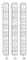
図9は、各遊技状態における入賞図柄組み合わせ(入賞役)に対する配当枚数を表している。
【0063】
ここで、内部当選と入賞、及び遊技状態について説明する。内部当選とは、前述の確率抽選処理において、サンプリングした乱数値と入賞確率テーブルとを照合した結果、当選と判定されて、該当入賞役の当選フラグが立てられた状態である。
【0064】
当選フラグは、原則すべての入賞役について存在するが、その特性によって、成立したゲームのみ有効であり、当選フラグを次回のゲームに持ち越さない小役と呼ばれる比較的払出枚数の少ない入賞役のものと、当選フラグが成立したゲームだけではなく、入賞が発生するまで持ち越され、ビッグボーナス(BB)やレギュラーボーナス(RB)と呼ばれる、入賞役の内部抽選確率が増加し、大量のコイン払出が得られるボーナス役と呼ばれる入賞役のものとに大別される。
【0065】
小役の例としては、例えば、左リールの有効ライン上に停止するだけで入賞となる「チェリー」入賞役や、有効ライン上に図柄が3個揃って停止すると入賞となる「ベル」入賞役や「スイカ」入賞役などがある。またボーナス入賞役として、レギュラーボーナスやビッグボーナスがある。レギュラーボーナス(RB)は、有効入賞ライン上に、例えば「BAR−BAR−BAR」が揃うことで発生し、まず入賞時に15枚の払出を行う。そして1枚がけのボーナスゲーム(JACゲーム又は役物遊技という)を、12回遊技するか、8回入賞が発生するまで行える。ビッグボーナス(BB)は有効ライン上に、例えば「赤7−赤7−赤7」が揃うことで発生し、まず入賞時に15枚の払出を行う。そしてBB中一般遊技と呼ばれる小役やRBの入賞確率が増加した遊技を最大30回遊技でき、その期間中にRBを最大3回遊技できる。一般遊技からのRB入賞は、例えば「BAR−BAR−BAR」が揃うことで発生するが、BB中の一般遊技からのRB入賞は、「リプレイ−リプレイ−リプレイ」揃うことで発生する。リプレイ入賞役は、入賞すると投入したコインの枚数と同数のコインが自動投入されるので、次回のゲームではコインを投入せずに遊技を行うことができる。シングルボーナス(SB)は有効ライン上に、例えば「剣付き7−剣付き−剣付き7」が揃うことで発生し、まず入賞時に15枚の払出を行う。そしてJACゲームを1回行うことができる。このSBは「ボーナス」との名称が付いているが、当選フラグの持ち越しはせず、当選フラグが有効なのは小役と同様にその回のゲームのみである。
【0066】
次に遊技状態の説明をする。遊技状態は、ボーナス入賞役の当選フラグの有無で大きく3つの状態に区分され、未だボーナス役が内部当選すらしていない一般遊技状態、確率抽選処理において内部当選したが、未だボーナス入賞図柄が有効ライン上に揃わず入賞が発生していない状態であるボーナス内部当選状態(ボーナス内部当選中、ボーナス内部当たり中とも言う)、ボーナス内部当選中に有効ライン上にうまく入賞図柄を揃えられ、ボーナス遊技を遊技している状態であるボーナス遊技状態(ボーナス作動中とも言う)とに大別される。
【0067】
更にボーナス内部当選中は、そのボーナス種別によりBB内部当選中とRB内部当選中に区分される。また、ボーナス作動中もBB作動中とRB作動中に区分される。
【0068】
また、ボーナス入賞役以外にも、大量のコインを獲得できる遊技者にとって有利な遊技状態が存在する。
【0069】
例えば、「集中機」と呼ばれる、一般遊技中のSBの入賞確率テーブルについて、高確率テーブル(例えばSB内部当選確率1/2)と低確率テーブル(例えばSB内部当選確率1/20)とを用意し、低確率テーブル使用時には高確率テーブルに切り替える抽選を(一般的に「突入抽選」という)行い、逆に高確率テーブル使用時には低確率テーブルに切り替える抽選を(一般的に「パンク抽選」という)行い、高確率テーブル使用時にコインが漸増していくような特定状態が知られている。
【0070】
また、「AT(アシストタイム)機能」と呼ばれ、決して同時に入賞しえない入賞役を複数設定し(例えば「ベル−ベル−赤7」、「ベル−ベル−青7」、「ベル−ベル−白7」の入賞役を備え、右リールの「赤7」、「青7」、「白7」、それぞれの図柄の間隔を4コマ以上とる)、通常状態では内部当選役の種別を報知しないので、どの「7」を狙っていいのかがわからず、理論上、内部当選後1/3でしか入賞できないが、AT期間よばれる内部当選種別を報知する状態となると、狙うべき「7」図柄の種別がわかるので、目押しさえ正確に行えば、理論上、内部当選後100%で入賞が可能となり、コインが漸増していくような特定状態が知られている。
【0071】
また、「ST(スーパータイム)機能」と呼ばれ、1の内部当選役に対し、予め定められた停止順序を行わないと、仮に入賞役が内部当選し、かつ正確な目押し操作を行っても、入賞図柄が揃わない停止制御を行うものもある。例えば図10に示すように入賞役「ベル」について、停止順序テーブルを”NO.1”から”NO.6”まで6種類用意し、確率抽選処理においてベルが内部当選したときに、使用する停止テーブルを乱数抽選などで選択する。例えば今回のゲームでテーブル”NO.3”の停止テーブルが選択された場合、第1停止操作で中停止ボタン15C、第2停止操作で左停止ボタン15L、第3停止操作で右停止ボタン15Rを行うと入賞が発生する。それ以外の5種類の停止順序は、ベルが内部当選していても有効ライン上にベル図柄は揃わない停止制御が行われる。
【0072】
そして通常状態ではこの停止順序を報知ないので、理論上、内部当選後1/6でしか入賞できないが、ST期間と呼ばれる、選択された停止テーブルの種別を報知する、別の言い方をすれば停止順序すべき順番を報知する状態となると、理論上、内部当選後100%で入賞が可能となり、コインが漸増していくような特定状態が知られている。
【0073】
そして本実施例では、図9に示すように、入賞図柄が同一でも、遊技状態によって配当枚数を異ならせている。例えば、スイカ入賞役は一般遊技中及びボーナス内部当選中においては3枚の払出であるが、BB中一般遊技では15枚の払出である。また「リプレイ−リプレイ−リプレイ」は一般遊技中及びボーナス内部当選中はリプレイ入賞図柄であるが、BB中一般遊技ではRB入賞図柄となり、JACゲームにおいては15枚払出の役物入賞図柄となる。
【0074】
また本実施例では、ボーナス入賞役以外に、遊技者にとって有利な状況として前述の「ST」を採用し、一般遊技中に所定の条件を満たすとST遊技が作動する構成となっている。具体的には、SB入賞役又はベル入賞役に内部当選したとき、それぞれの入賞となる図柄の組み合わせを揃わせるために必要な停止順序の情報が遊技者に対して報知される。従って、この特定状態の期間中にSB入賞役又はベル入賞役が内部当選したとき、遊技者は報知されている停止順序に従い操作することで取りこぼしを発生することなく、確実に入賞を発生させることができる。
【0075】
図11は、前述の確率抽選処理に用いられる入賞確率テーブルを示す図である。乱数値は”0〜16383”の範囲で抽出され、各入賞役に対して定められた当選範囲に属したとき、該当入賞役の内部当選となる。例えば、今回のゲームで抽出した乱数値が”10000”だった場合、ベル入賞役の当選範囲”2299”〜”11024”に属するのでベル入賞役の内部当選となる。また、今回のゲームで抽出した乱数値が”15000”だった場合、ハズレの範囲”13669〜16383”に属するので、いずれの入賞役も内部当選せず、ハズレとなる。
【0076】
図12は、メイン制御回路101からの遊技情報コマンド表を示した図である。本実施例では、入賞判定やコイン払出などの制御を司るメイン制御回路101と、演出表示部21やスピーカ5L、5Rの制御を司るサブ制御回路201とが別基板で構成されており、サブ制御回路201にて処理される演出制御に、メイン制御回路で処理される入賞役の内部当選状態や、リールの停止状況についての遊技情報が必要となることから、両基板をストレートケーブルで接続し、必要な情報を逐次送信している。送信されるコマンドは、遊技者のスタートレバー13の操作時に送信される「スタートコマンド」、回転中のリール24L、24C、24Rを停止するために停止ボタン15L、15C、15Rが操作されたときに送信される「リール停止コマンド」、1回の遊技が全て終了したときに送信される「1遊技終了コマンド」がある。
【0077】
各コマンドは、2バイトで1種類のデータを表し、先行1バイトはそのコマンドの種別を、後続の1バイトはその内容を表す。スタートコマンドは6バイトのデータで構成され、データ種別としては「内部当選役」、「遊技状態」、「選択停止テーブル」の3種類で構成される。リール停止コマンドは1回の停止操作につき4バイトのデータで構成され、データ種別としては「停止順序」、「停止リール」の2種類で構成される。1遊技終了コマンドは4バイトのデータで構成され、データ種別としては「入賞種別」、「ボーナス遊技状態」の2種類で構成される。
【0078】
図13(a)は、パネル表示部7の正面図である。パネル表示部7は、透明アクリル板から形成される一枚板からなり、外部側からの物理的な衝撃を防御する役割を果たしている。図13(b)は絵柄シート20の正面図である。絵柄シート20は、透明フィルム材に半透明インクで絵柄を印刷したもので、本実施例では、シート左側に木の絵柄が印刷されている。図13(c)は、電子シャッター部22の正面図である。電子シャッター部22は液晶フィルムより構成され、電圧の印加状態により、透明/不透明の切り替えが実行される。また電子シャッター右側の各ランプ部と7セグメント表示部の表示領域は、電圧の印加状態の有無に関わらず透明状態が保持され、遊技者から常に視認可能な構成となっている。
【0079】
図14(a)は、電子シャッター部22が全領域について遮蔽状態(非印加状態)時のパネル表示部7の拡大図である。この表示状態は、例えばパチスロ遊技機1の電源が入っていないときの表示状態であり、リール24は電子シャッター22に隠れてしまい、遊技者からは視認できない状態となっているが、絵柄シートは、電子シャッター部22より手前(遊技者側)に設けられているので、電子シャッター部の制御状態には影響を受けず、遊技者から視認可能となっている。また、パネル表示部右側の各種ランプ表示部及び7セグメント表示部は、電子シャッター部22より筐体内部側に配置されているが、電子シャッター部22の該当表示領域は常時透明状態であるので、遊技者から視認可能な状態となっている。
【0080】
図15は、特別遊技状態であるST遊技中の演出画面を示す図である。図15(a)は、ST遊技中の演出制御の一例として、今回の遊技でベルが内部当選して、図10の停止テーブルのNo.5が選択された場合に、第1停止操作前に表示されるパネル表示部7を示す図である。本実施例では、ST遊技中の演出制御について、停止操作するべき停止ボタンに対応するリールの表示領域のみ電子シャッター部22を透過制御し、その他の表示領域を遮蔽制御することで、適切な停止操作を示唆する。停止テーブルNo.5は第1停止操作右停止ボタンなので、右リール24R以外の表示領域が遮蔽されて、回転中の右リール24Rのみが遊技者から視認可能となっており、遊技者に右停止ボタン15Rを停止操作すべきことを示唆している。ここで透過制御とは、背後のリール図柄が視認可能な状態に電子シャッター部を制御することであり、遊技者からリール図柄を視認可能な範囲であれば、完全な透明状態ではなく半透明状態であったり、また色が付いた状態であってもよい。同様に遮蔽状態についても、光を完全に通さない状態だけではなく、背後のリール図柄が視認できない程度であれば、ある程度の半透明状態も含まれる。
【0081】
図15(b)は、図15(a)の状態で、遊技者が右停止ボタン15Rを停止操作したときのパネル表示部7を示す図である。右停止ボタン第1停止は正当な停止操作なので、図15(a)において、回転中の右リール24R全体が視認されていた右リール24Rの表示領域について、内部当選役であるベルの図柄のみ視認可能として、その他の表示領域を遮蔽することで、正しい停止操作であったことを遊技者に報知している。また、図15(a)において遮蔽されていた左リール24Lの表示領域が透過状態となって、回転中の左リール24Lが視認可能な状態となっており、遊技者に左リール24Lを操作すべきことを示唆している。
【0082】
図15(c)は、図15(b)の状態で、遊技者が左停止ボタン15Lを操作したときのパネル表示部7を示す図である。左停止ボタン第2停止は正当な停止操作なので、図15(b)において、回転中の左リール24L全体が視認されていた左リール24Lの表示領域について、内部当選役であるベルの図柄のみ視認可能として、その他の表示領域を遮蔽することで、正しい停止操作であったことを遊技者に報知している。また図15(b)において遮蔽されていた中リール24Cの表示領域が透過状態となって、回転中の中リール24Cが視認可能な状態となっており、遊技者に残りの中リール24Lを操作すべきことを示唆している。
【0083】
図16(a)は、ST遊技中の停止操作を全て正しく行って入賞が発生したときのパネル表示部7を示す図である。図16(a)では、入賞役であるベル図柄の部分だけ電子シャッター部が透過制御され、リール24上のベル図柄が視認可能となっているとともに、演出表示部21に「GET」との文字が表示されて、ベルが入賞したことを遊技者に報知している。
【0084】
図16(b)は、ST遊技中の停止操作を誤って行って、取りこぼしが発生したときのパネル表示部7を示す図である。例えば、図15(b)の状態において、正しくは左停止ボタン15Lを操作すべきところを、誤って中停止ボタン15Cを操作してしまった場合などに表示され、表示部中央に大きく「×」が表示され、遊技者に誤った停止操作であったことを報知している。
【0085】
図16(a)及び(b)において実行された演出制御は、一定時間表示された後、図16(c)に示されるように全ての遮蔽領域が透過制御され、1回の遊技における演出制御が終了する。
【0086】
図17は、リール24L、24C、24Rが全て停止した後に、所定の確率で発生する予告演出画面を示す図である。具体的な演出の流れとしては、まず、回転中のリール24L、24C、24Rがパネル表示部7越しに表示され(図17(a))、その後、遊技者の停止操作により、全てのリールが停止する(図17(b))。全てのリールが停止した後に、電子シャッター部22が遮蔽状態となり、図17(c)に示すように、表示されていたリール24L、24C、24Rが電子シャッター部の背後に隠れた状態となる。
【0087】
次に、今回のゲームの内部当選役に基づいた予告演出を実行する。本実施例の予告演出は、演出表示部21上で表示されるベル図柄の表示位置と、停止表示されたリール24L、24C、24Rのベル図柄の停止位置とがどの程度一致しているかにより、ボーナス入賞役成立の信頼度を表す内容となっている。図19(a)は、予告演出発生テーブルを示す図である。予告演出発生テーブルは、確率抽選処理において、BB、RB、スイカ、SBが内部当選した場合に、予告演出を実行させるか否かの抽選を実行する際に参照される。例えば今回のゲームでスイカが内部当選し、演出選択用乱数値が15の場合、演出発生となるが、演出選択用乱数値が同じ15であっても内部当選役がSBである場合には演出が発生しない。
【0088】
図19(b)は、演出種別選択テーブルを示す図である。演出種別選択テーブルは、予告演出発生テーブルにて、予告演出の発生が決定された場合に、その演出内容を決定する際に参照される。演出は、リール24L、24C、24Rにおけるベル図柄停止位置と、演出表示部21におけるベル図柄停止位置をどれだけの精度で一致させるかにより区分され、一致しているほどボーナス入賞役が内部当選している確率が高い。例えば図中のベル表示個数が「全て」とは、両者の表示位置が全て一致していることを表し、「出現数−2」とは、両者の表示位置が最大2カ所不一致となることを表している。例えば、今回のゲームで内部当選役が「SB」、演出選択用乱数値が118であった場合、「出現数−4」の演出が選択される。ここで、リール24L、24C、24Rに停止表示されているベル図柄が、例えば2個しかないときなどは、全ての表示位置が不一致となるような演出態様が選択され、例えば5個表示されている場合は、4個の表示位置が不一致で表示され、1個の表示位置が一致して表示される。
【0089】
図18は予告演出態様の具体例を示す図である。図18(a)は、リール24L、24C、24Rが図17(b)の表示態様で停止しているときに、図19(b)の演出種別選択テーブルにおいて、「出現数−2」、「出現数−3」、「出現数−4」、「出現数−5」のいずれかが選択されたときに表示されるものであり、図17(b)のリール停止態様において、リール上においては中リール24C中段と右リール24R上段にベル図柄が表示されているにも関わらず、演出表示部21では中リール下段と右リール中段にベル図柄が表示されており、両者の表示位置が一致していない信頼度の低い予告演出であることがわかる。
【0090】
図18(b)は、リール24L、24C、24Rが図17(b)の表示態様で停止しているときに、図19(b)の演出種別選択テーブルにおいて、「出現数−1」のいずれかが選択されたときに表示されるものであり、リール上においては中リール24C中段と右リール24R上段にベル図柄が表示されているときに、演出表示部21では中リール中段と右リール中段にベル図柄が表示されており、右リール24Rは表示位置が不一致であるが、中リール24Cは表示位置が一致しているので信頼度の高い予告演出であることがわかる。
【0091】
図20は、BR発生及びBR継続回数抽選テーブルを示す図である。本実施例では、BRを発生させるか否か、及びBR継続回数を、所定の入賞役が内部当選した場合に一定の確率で抽選することにより決定する。テーブルでは、スイカ内部当選時に16/128の確率で、2枚チェリーの内部当選時に11/128で、ハズレ時の25/128でBRが発生する。
【0092】
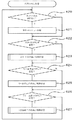
次に、メイン制御回路101とCPU103の制御動作について図21から図23に示すメインフローチャートを参照して説明する。
【0093】
初めに、CPU103は、ゲーム開始に先立ち、初期化処理を行う(ステップ「以下STと略記する」501)。具体的には、RAM105に記憶されている前回ゲームのステータスや通信データのクリア、ゲームに必要な遊技パラメータの書き込み、シーケンスプログラムの開始アドレスの設定などを行う。
【0094】
次に、CPU103は、コインの自動投入要求があるか、すなわち、前回の遊技でリプレイ入賞したか否かを判別する(ST502)。この判別が”YES”のときは、投入要求分のコインを自動投入し(ST503)、ST505の処理に移る。ST302の判別が”NO”のときは、新たなコインの投入があるか、すなわち、遊技者がコイン投入口11にコインを投入したことによる投入コインセンサ117からの入力があるか、各種BETスイッチ8、9、10が操作されたことによる入力があるか否かを判別する(ST504)。この判別が”YES”のときは、ST305に移り、”NO”であればBET操作がなされるまで入力信号の監視を続ける。
【0095】
次に、CPU103は、スタートレバー13の操作による入力があるか否かを判別する(ST505)。この判別が”YES”のときは、ST506に移り、”NO”のときは、スタートレバーが操作されるまで入力信号の監視を続ける。
【0096】
次に、確率抽選処理を行う(ST506)。確率抽選処理は、まず抽選用乱数値を、乱数発生器108及びサンプリング回路109を用いて”0〜16383”の範囲で抽出する。そして遊技状態と投入メダル枚数に応じて当選となる乱数値範囲(当選範囲)を設定している入賞確率テーブル(図11)を用いて、抽出した乱数値がどの当選範囲に属するかを判別し、該当する内部当選役(当選フラグ)を決定する。
【0097】
次に、ボーナス入賞役が内部当選であった場合に、所定の確率でWINランプを点灯させるWINランプ点灯処理を行う(ST507)。
【0098】
次に、遊技開始時のメイン制御回路101の遊技情報をサブ制御回路に送信する(ST508)。送信されるコマンドとしては、図12の遊技情報コマンドの「スタートコマンド」に示すように、上記確率抽選処理で決定された当選フラグや、今現在の遊技状態、当選フラグに応じて決定された停止テーブル番号などが送信される。
【0099】
次に、前回のゲームでセットされた1ゲーム監視用タイマーが規定時間、例えば4.1秒を経過しているか否かを判定し(ST509)、”YES”のときは、次ゲーム用の1ゲーム監視用タイマーをセットし(ST511)、”NO”のときは、残り規定時間を消化(ST510)した後、次ゲーム用の1ゲーム監視用タイマーをセットする(ST511)。
【0100】
次に、CPU103は、モータ駆動回路111を制御し、リール24L、24C、24Rを回転させる処理(リール回転処理)を行う(ST512)。リール回転処理は、リール24L、24C、24Rが停止している状態から加速処理を行って、一定の速度に達した後、定速回転処理を行うものである。この定速回転の状態になったことを条件に、停止ボタン15L、15C、15Rが有効化され、リール24L、24C、24Rの停止操作が可能となる。
【0101】
次に、CPU103は、停止ボタン15L、15C、15Rのいずれかが操作されたか(停止ボタンオンか)否か、すなわち、遊技者によって停止ボタン15L、15C、15Rが操作されたときにリール停止信号回路118から送られてくる停止信号の有無を判別する(ST513)。この判別が、”YES”のときは、ST515に移り、”NO”のときはST514の処理に移る。ST514の処理では、自動停止タイマーの値が”0”であるか否かを判別する。自動停止とは、リールの回転が開始してから一定期間経過(例えば40秒)した場合、たとえ停止ボタン15L、15C、15Rが操作されずにリール24L、24C、24Rが回転していても、自動的に停止制御を行う処理のことである。そして、この判別が”YES”のとき、すなわち自動停止タイマーが”0”であった場合は、リールを自動的に停止するためST515に移り、”NO”のときは、引き続き停止操作の受付を監視するためST513の処理に移る。
【0102】
ST515の処理では、CPU103は、「滑りコマ数決定処理」を行う。この「滑りコマ数決定処理」では、停止操作された停止ボタンに対応するリールの滑りコマ数を決定する。ここで、「滑りコマ数」とは、停止ボタン15L、15C、15Rが操作されたときに表示窓43L、43C、43Rに表示されている図柄位置(これを「停止操作位置」という)から何図柄分滑らせてリールを停止させるか(実際に停止した位置を「停止位置」という)、その滑る図柄の数(コマ数)のことをいう。
【0103】
次に、CPU103は、停止操作された停止ボタンに対応するリールを、決定した滑りコマ数分回転させてから停止するようにモータ駆動回路111を制御する(ST516)。
【0104】
次に、CPU103は、リールが停止したことを示す「リール停止コマンド」をサブ制御回路201に送信する(ST517)。リール停止コマンドは遊技情報コマンドの「リール停止コマンド」に示すように、停止順序ステータス(今回の停止操作が何番目の停止操作か)と、停止リールステータス(どのリールが停止操作されたか)をサブ制御回路201に送信する。
【0105】
次に、CPU103は、全てのリールが停止したか否かを判別する。この判別が”YES”であればST519に移り、”NO”であれば、回転中のリールがまだ残っているということなのでST513に移る。
【0106】
次に、CPU103は、入賞検索処理を行う(ST519)。この入賞検索処理では、表示窓43L、43C、43Rに表示された図柄の停止態様が、入賞成立を示すものであるか否かを判定し、入賞成立を示す停止態様であるときは、該当する入賞役の入賞フラグをRAM105に記憶する。具体的には、センターラインL1上の図柄のコードナンバーを、ROM104に記憶されている入賞図柄組み合わせテーブルと照合することで判定を行う。
【0107】
続いて、入賞フラグと、当選フラグが整合するかを照合し、今回の入賞が正常であるか否かを判別する(ST520)。この判別が”NO”のときはイリーガルエラーを表示し、遊技プログラムの実行を中止する。ST520の判別が”YES”のときは、成立した入賞役の種別と遊技状態に応じたコインの払出を行う(ST522)。
【0108】
次に、今回の遊技が終了することで、遊技状態が変更する場合はその移行処理を行う(ST523)。例えば、ボーナス遊技の最終入賞だった場合や、今回の遊技でボーナスが内部当選した場合や、有効ライン上に「7−7−7」と図柄が停止して、ボーナス遊技が開始した場合などがある。
【0109】
続いて、成立した入賞役の種別や、遊技状態などを、図12の遊技情報コマンド表に示す「1ゲーム終了コマンド」としてサブ制御回路に送信する(ST524)。
【0110】
次に、サブ制御回路201のサブCPU203の制御動作について説明する。
【0111】
図24は、割り込み処理1を示すフローチャートである。割り込み処理1は3ms毎の割り込み処理にて実行され、メイン制御回路101から送信されてくる遊技情報コマンドや、タッチパネルからの入力信号をサブRAM205に格納する処理を行う。
【0112】
まず、サブCPU203は、入力バッファをチェックして(ST600)、入力バッファに入力信号があるかを判別し(ST601)、”YES”であれば、受信フラグをオンし(ST602)、受信コマンドの内容をサブRAM205にセットして(ST603)、処理を終了する。判別が”NO”であれば、そのまま処理を終了する。
【0113】
図25は、サブ制御回路側のメイン処理を示すフローチャートである。まずサブCPU203は、サブRAM205の受信フラグをチェックし、タッチパネルからの操作入力があるか否かを判別し(ST620)、”YES”であれば、サポートメニュー処理を実行し(ST621)、ST622に移り、判別が”NO”であれば、ST621をスキップしてST622に移る。サポートメニュー処理は、入力に応じたサポートメニューの表示、編集を行うものである。
【0114】
次にスタートコマンドを受信したか否かを判別し(ST622)、”NO”であればST623をスキップしてST624に移り、”YES”であれば、スタート時の演出制御処理を実行する(ST622)。スタート時の演出制御処理は、BR中であった場合にBRの制御処理を行うものである。詳細は後述する。
【0115】
次にリール停止コマンドを受信したか否かを判別し(ST624)、”NO”であればST625をスキップしてST626に移り、判別が”YES”のときはリール停止時の演出制御処理を実行する(ST625)。リール停止時の演出制御処理は、BR発生抽選処理やBR中における停止順序の報知、及び報知内容と実際の停止操作との整合性に応じた演出を行うものである。詳細は後述する。
【0116】
次に、1ゲーム終了コマンドを受信したか否かの判別を行い(ST626)、判別が”NO”であれば、ST627をスキップし、ST620の処理に戻り、同様の処理を繰り返し行う。判別が”YES”であれば、次に1遊技終了時の演出制御処理を実行する(ST627)。1遊技終了時の演出制御処理は、予告演出処理や、現在BR中である場合に、BR継続回数を更新処理を実行する。詳細は後述する。
【0117】
そしてST627の処理が終了した後はST620に戻り、同様の処理を繰り返し行う。このようにサブ制御回路201のメインフローチャートは、メイン制御回路101から送信されてくる遊技情報コマンドに基づいて、該当する演出処理に分岐させる処理を繰り返し行うものである。
【0118】
図26は、スタート時の演出制御処理を示すフローチャートである。まずサブCPU203は、BR発生抽選処理を行う(ST660)BR発生抽選処理は、特別遊技であるバトルラッシュを発生させるか否かを決定する処理である。詳細は後述する。次にBR実行処理を行う(ST680)。BR実行処理は、BR中に停止順序報知を行うものである。詳細は後述する。
【0119】
図27は、BR発生抽選処理を示すフローチャートである。まずサブCPU203は、サブRAM205に記憶されているBRフラグをチェックして、現在BR遊技中か否かを判別し(ST661)、”YES”であれば、そのままスタート時の演出制御処理に復帰する。判別が”NO”であれば、図20のBR発生及びBR継続回数抽選テーブルを参照して、いずれかのBR継続回数に当選したか否かを判別し(ST662,663)、判別が”NO”(ハズレ)であればスタート時の演出制御処理に復帰する。判別が”YES”であればサブRAM205のBRフラグをオンし、BR継続回数に当選した継続回数をセットし(ST664)、BR発生演出を行って(ST665)、スタート時の演出制御処理に復帰する。
【0120】
図28はBR実行処理を示すフローチャートである。まずサブCPU203は、サブRAM205のBRフラグ及びBR退避フラグをチェックして、現在BR中か,又はBR中にボーナスが発生してBRが一時中断しているか否かを判別し(ST681)、”NO”であれば、BR中ではないということなので、そのままスタート時の演出制御処理に復帰する。判別が”YES”であれば、次にサブRAM205の受信フラグをチェックして、ボーナス入賞役に内部当選したか否かを判別し(ST682)、”YES”であれば、BRを中断し、ボーナス遊技を消化させるため、サブRAM205のBRフラグをオフ、BR退避フラグをオンにして(ST683)、スタート時の演出制御処理に復帰する。
【0121】
ST682の判別が”NO”であれば、次にBR退避中であった場合に、BRを再開させるために、サブRAM205のBR退避フラグをオフし、BRフラグをオンにする(ST684)。次に、BR継続回数を全て消化したかチェックするため、サブRAM205のBR継続回数をチェックし、継続回数が0になったか否かを判別して(ST685)、”YES”であれば、BR終了ということなので、BRフラグをオフにして(ST686)、スタート時の演出制御処理に復帰する。
【0122】
判別が”NO”であれば、まだBRを規定ゲーム数消化していないということなので、次にサブRAM205の受信フラグをチェックして、今回のゲームでベルかSBが内部当選したか否かを判別し(ST687)、”YES”であれば、サブRAM205の受信フラグに記憶されている選択された停止テーブル種別を参照して適切な停止順序を報知し(ST688)スタート時の演出制御処理に復帰する。判別が”NO”であれば、何も報知せずスタート時の演出制御処理に復帰する。
【0123】
次に、BR中に停止ボタン15L、15C、15Rを操作したときの演出制御処理について説明する。図29はリール停止時の演出制御処理を示すフローチャートである。まずサブCPU203は、サブRAM205のBRフラグをチェックし、現在BR中か否かを判別し(ST700)、”NO”であれば、そのままサブ側メイン処理に復帰する。判別が”YES”であれば、次に、サブRAM205の受信フラグの停止コマンドをチェックし、停止順序データと停止リールデータを、使用テーブルNoデータと照合し、今回の停操作が停止テーブルに指定されている順序通りの正当な押し順か否かを判別し(ST701)、”YES”であれば、正当な押し順で停止操作された旨を表示し(ST702)、判別が”NO”であれば、誤った押し順で停止操作された旨を表示し(ST703)、サブ側メインフローに復帰する。
【0124】
次に全てのリールが停止した後に行われる演出制御処理について説明する。図30は1遊技終了時の演出制御処理を示すフローチャートである。まずサブCPU203は、内部当選役の予告演出を発生させるか否かを決定する予告演出発生処理を実行し(ST720)、次に、現在の遊技状況がBR中であった場合に、関連パラメータを更新するパラメータ更新処理を実行する(ST740)。そして、予告演出発生処理にて、予告演出の発生が決定された場合に演出処理を実行し(ST760)、サブ側メインフローに復帰する。
【0125】
図31は予告演出発生処理を示すフローチャートである。まずサブCPU203は、サブRAM205の受信フラグをチェックし、現在の遊技状態が一般遊技中であるか否かを判別し(ST721)、”YES”であれば、図19(a)の予告演出発生テーブルを参照して、予告演出の発生抽選を実行し(ST722)、当選したか否かを判別し(ST723)、”YES”であれば、図19(b)の演出種別選択テーブルを参照して、予告演出の形態を決定する演出形態決定処理を実行し(ST724)、1遊技終了時の演出制御処理に復帰する。判別が”NO”であれば、そのまま1遊技終了時の演出制御処理に復帰する。
【0126】
図32はパラメータ更新処理を示すフローチャートを示す図である。まずサブCPU203は、サブRAM205に記憶されている受信フラグの1遊技終了コマンドをチェックして、現在の遊技状態がボーナス遊技中か否かを判別し(ST741)、”YES”であれば、BR中ではあり得ないので、そのまま1遊技終了の演出制御処理に復帰する。判別が”NO”であれば、次にサブRAM205に記憶されているBRフラグをチェックして、現在BR中か否かを判別し(ST742)、”NO”であれば、そのまま1遊技終了の演出制御処理に復帰する。判別が”YES”であれば、サブRAM205のBR継続回数カウンタを減算し(ST743)、1遊技終了の演出制御処理に復帰する。
【0127】
本実施例では、課題を達成したことにより発生する遊技者に有利な状況としてST期間を用いて説明したが、前述のATや、遊技者に有利な状況として、他にも特定の入賞役の当選フラグを成立させたり、入賞役の内部当選確率を増加させたりしてもよい。
【0128】
また本発明は、上述した実施例のようなスロットマシンの他、電気的表示装置を備えたパチンコ遊技機やアーケードゲーム機、更には上述した機能をソフトウェア上で擬似的に実行する家庭用ゲームなどにおいても同様に適用できる。
【0129】
【発明の効果】
本発明によれば、リールが全て停止した状態で電子シャッターを作動させることになるので、リール回転中における電子シャッター制御の問題点である目押しの阻害を考慮することなく、表示パネル全面にわたって電子シャッターを遮蔽状態に制御できるので、大きく鮮明な画像演出を実行することが可能となる。
【図面の簡単な説明】
【図1】実施例のパチスロ遊技機の外観を示す斜視図。
【図2】パネル表示部の断面図。
【図3】パネル表示部の正面図。
【図4】メイン制御回路を示すブロック図。
【図5】サブ制御回路を示すブロック図。
【図6】入賞ラインを示す図。
【図7】リール及びバックランプを示す図。
【図8】リールの外周面上に表される図柄列を示す図。
【図9】各入賞役の図柄組み合わせ及び配当枚数を示す図。
【図10】入賞役ベル内部当選時に選択される停止テーブルを示す図。
【図11】入賞確率テーブルを示す図。
【図12】サブ制御回路へ送信されるコマンド一覧を示す図。
【図13】パネル表示部の拡大図。
【図14】パネル表示部の拡大図。
【図15】ST遊技中の演出画面を示す図。
【図16】ST遊技中の演出画面を示す図。
【図17】予告演出画面を示す図。
【図18】予告演出画D面を示す図。
【図19】予告演出発生テーブル、及び演出種別選択テーブルを示す図。
【図20】BR発生及びBR継続回数抽選テーブルを示す図。
【図21】メイン制御回路の処理を示すフローチャート。
【図22】メイン制御回路の処理を示すフローチャート。
【図23】メイン制御回路の処理を示すフローチャート。
【図24】「割り込み処理1」を示すフローチャート。
【図25】サブ側メインフローを示すフローチャート。
【図26】スタート時の演出制御処理を示すフローチャート。
【図27】BR発生抽選処理を示すフローチャート。
【図28】BR実行処理を示すフローチャート。
【図29】リール停止時の演出制御処理を示すフローチャート。
【図30】1遊技終了時の演出制御処理を示すフローチャート。
【図31】予告演出発生処理を示すフローチャート。
【図32】パラメータ更新処理を示すフローチャート。
【符号の説明】
1 パチスロ遊技機
2 キャビネット
3 全面ドア
4 遊技状態表示ランプ
5 スピーカ
6 配当表
7 パネル表示部
8 1−BETスイッチ
9 2−BETスイッチ
10 MAXBETスイッチ
11 コイン投入口
12 C/Pスイッチ
13 スタートレバー
14 コイン投入部
15 停止ボタン
16 コイン受皿
17 コイン払出口
20 絵柄シート
21 演出表示部
22 電子シャッター部
23 冷陰極管
24 リール
30 REPLAYランプ
31 WAITランプ
32 WINランプ
33 ボーナス中情報表示部
34 クレジット表示部
35 払出表示部
36 スタートランプ
40 リール帯
41 ランプハウジング
42 リールバックランプ
43 表示窓
101 メイン制御回路
102 マイクロコンピュータ
103 CPU
104 ROM
105 RAM
106 クロックパルス発生回路
107 分周器
108 乱数発生器
109 サンプリング回路
110 I/Oポート
111 モータ駆動回路
112 ステッピングモータ
113 ホッパー駆動回路
114 ホッパー
115 リールインデックス検出回路
116 ランプ駆動回路
117 投入コインセンサ
118 リール停止信号回路
119 払出検知回路
120 コイン検出部
121 7セグ駆動回路
201 サブ制御回路
202 サブマイクロコンピュータ
203 サブCPU
204 サブROM
205 サブRAM
206 サブマイクロコンピュータINポート
207 サブマイクロコンピュータOUTポート
240 リールバックランプ制御回路
250 画像制御回路
251 画像制御CPU
252 画像制御ROM
253 画像制御RAM
254 画像IC
255 画像ROM
256 ビデオRAM
257 画像制御回路INポート
258 画像制御回路OUTポート[0001]
TECHNICAL FIELD OF THE INVENTION
The present invention relates to a symbol display device such as a slot machine, a pachinko gaming machine, and the like, which has a variable display means for displaying various symbols in a variable manner and a function of controlling the variable display and giving a profit to a player according to the result. It relates to a combination gaming machine.
[0002]
[Prior art]
Conventionally, a slot machine is a typical example of this type of gaming machine. The slot machine is provided with a plurality of rotating reels in which a plurality of symbols are arranged on the outer circumference, and a symbol combination when each of the rotating reels stops is in a predetermined stopped state, for example, when the same symbols are aligned in a straight line , Winning coins and premiums. In general, various contingencies are often added in order to win this prize, and it is important to have a gambling element that the player's skill can not completely control the outcome of the game. It is a feature.
[0003]
In order to realize this "accidentality", various methods have been conventionally taken, but recently, using a microcomputer, after performing a winning prize lottery by software, a reel stop control is performed according to the lottery result. The mainstream is a slot machine that employs a control method called "first-stage determination." For example, a slot machine described in Japanese Patent Publication No. 3-72313 relates to a slot machine with a stop button called a so-called pachislot machine, and random number sampling means for sampling a random number based on a start lever operation of a player; A winning probability table divided into random numbers ranges of "big hit", "medium hit", "small hit" according to the size of the role is provided, and the sampled random value is included in the winning section of the winning probability table In this case, it is determined that the winning combination has been won, and a hit (winning) flag for the winning combination is established. These winning flags include, for example, a "small win" in which about 10 coins can be paid out when a predetermined symbol (for example, a "bell" symbol or a "cherry" symbol) is arranged on the activated winning line. It is generated when the winning flag of the winning combination called and a predetermined symbol (for example, “7” symbol or “BAR” symbol) are arranged, and a certain number of games are played, and a winning is more easily generated than in a normal gaming state. There is a winning flag of a winning combination called a “bonus combination” that can provide a large amount of coin payout of about 100 to 400 coins.
[0004]
The state in which the winning flag is established is a state generally called “internal winning”, and only the permissible winning combination is allowed to be aligned on the winning line, but the prize has not yet actually occurred. Absent. In order to generate a prize, it is necessary to operate at a timing (usually within 4 frames) at which the rotating prize symbol can be stopped on the prize line, that is, to perform a so-called "gaze". A so-called “missing” occurs in which no prize is generated despite the fact that the player has been internally won.
[0005]
This dropout can be said to be a failure in eyesighting in a broad sense, but there are several patterns for the cause. First, although the design to be aimed at is determined, the changing design cannot be recognized. Secondly, there are a plurality of winning combinations that may have been internally won in the game this time, and there are a plurality of winning combinations that may have been internally won in this game, However, there is a pattern in which an appropriate stop operation is performed and a failure occurs.
[0006]
The former can be expected to improve the accuracy to some extent if they become familiar with the pushing technique, but the latter needs to grasp the invisible internal winning state, so even if the player is skilled at pushing, No improvement in accuracy can be expected.
[0007]
Conversely, if only the internal winning combination is informed, it can be said that it is possible to realize a gaming state such as a bonus game in which a large amount of coins can be obtained even in a normal gaming state, and such a pachislot unique When the predetermined conditions are met using the playability of the game, the internal winning is determined for a predetermined period, and furthermore, the type of the internal winning combination is notified to reduce the number of missed, and no notification is performed. There are gaming machines that have a function called "assist time (AT)" that has realized a large amount of coin payout compared to games. This belongs to “general game” in distinction of “game state” described later, but the actual coin payout can be set to a specification comparable to the bonus game.
[0008]
Similarly, there is a function called “super time (ST)” as a function for providing a large or small coin payout depending on whether or not to support “winning” in the “internal winning state”. This is when a spinning reel is controlled to stop by the player's stop button operation, a plurality of "stop tables" are prepared to determine how many frames to slide and stop from the symbol position where the stop operation is performed. If a stop table to be used every time an internal win is determined by random number lottery, and the stop operation is not performed in the stop operation order set in the stop table, even if the eye-pushing timing is activated on the winning line, Even if it is operated at the timing when it can be stopped, it is configured to perform stop control so as not to generate a prize, and by providing a state of "notifying" and a state of "not notifying" the type of the selected stop table. As with the "AT function" described above, a large amount of coins payout equivalent to a bonus game is realized.
[0009]
For example, if there are three stop buttons for stopping the left reel, stopping the middle reel, and stopping the right reel, "stop left, stop middle, stop right", "stop left, stop right, stop middle" according to the operation order. , "Right stop, Left stop, Middle stop", "Middle stop, Right stop, Left stop", "Middle stop, Left stop, Right stop" are prepared and the operation order of the stop table determined by random number lottery If the player does not perform the operation as described above, a winning is not generated.
[0010]
The player plays the game while hoping that these special games will occur, but since the probability of occurrence of the special game itself is very low, in order to maintain the expectation of the player during the normal game, The currently installed pachislot machines are equipped with various announcement directing functions. The announcement performance includes a notification that the winning combination and the above-mentioned AT game and ST game are internally won, and a notification that the lottery probability of these special games has shifted to a high probability state. The notification is made to the player by using a blinking mode of lamps provided on the left and right sides of the display unit, an image displayed on the liquid crystal display device, and the like.
[0011]
[Problems to be solved by the invention]
However, since these effect display devices are naturally installed at positions different from the reel installation positions, depending on the game situation, the user must always look at the reel to check the display contents of the effect display device. There is a problem that the user is required to move and the feeling of fatigue increases.
[0012]
There are also gaming machines that arrange liquid crystal panels and EL panels in front of the reels and execute various image effects. However, the reel design behind it is inevitably seen through and interferes with the image effects, resulting in a clear image. It was difficult to express.
[0013]
SUMMARY OF THE INVENTION It is an object of the present invention to provide a gaming machine that pays out a large amount of coins by suggesting an operation method that is advantageous to the player. The purpose is to provide.
[0014]
[Means for Solving the Problems]
The gaming machine of the present invention is provided with variable display means for performing variable display of various symbols, lottery means for performing a lottery of a winning combination, stop control means for controlling and controlling the variable display, and provided in front of the variable display means. In a gaming machine comprising: a shielded means, and a shield control means for changing and controlling a transparent state in which the symbol can be visually recognized by the player, and a shielded state in which the symbol cannot be visually recognized, according to the operation of the stop control means. The shielding control means controls to change at least a part of the shielding means to a shielding state on condition that all of the variable display is stopped.
[0015]
In the present invention, an effect display section made of a transparent liquid crystal is provided in front of the reel as the variable display means to perform various effect controls, and furthermore, a liquid crystal film is provided between the reel and the effect display section. An electronic shutter unit is provided, and a clear effect image is provided by executing transmission / shielding control of the electronic shutter according to a game situation. In particular, after all the reels have stopped, the electronic shutter is operated over the entire display panel to perform the effect control, thereby providing an image having an impact.
[0016]
According to the above configuration, the electronic shutter is operated in a state where all the reels are stopped. Therefore, the display panel can be operated without taking into account the obstruction of the eye pressing which is a problem of the electronic shutter control during the rotation of the reel. Since the electronic shutter can be controlled to be in the shielding state over the entire surface, it is possible to execute large and clear image effects.
[0017]
Further, in the second aspect of the present invention, the shielding control unit controls at least a part of a panel display unit in the first control state when the variable display unit is performing variable display. And
[0018]
In an embodiment described later, the control timing of the electronic shutter is controlled in a first control state, which is a transmission state, so as not to hinder the eyes when the reel serving as the variable display means is rotating. Is stopped, the control is performed in the second control state, which is the shielding state.
[0019]
According to the above-described configuration, the inconvenience of not being able to push the reel symbols due to the electronic shutter being in a closed state while the reels are still rotating can be eliminated, and the interest of the game increases.
[0020]
Further, in a third aspect of the present invention, the shielding means comprises an electronic shutter.
[0021]
In an embodiment described later, a liquid crystal film is taken as an example of an electronic shutter, and a switching between a transmission state and a shielding state is performed according to a voltage application state.
[0022]
According to the above-described configuration, it is possible to instantaneously switch between transmission and shielding depending on the game situation, and it is possible to control the shielding area in a software manner, thereby enabling more detailed effect control.
[0023]
BEST MODE FOR CARRYING OUT THE INVENTION
FIG. 1 is an external view of a slot machine with a stop button, which is a so-called pachislot gaming machine, which is an embodiment of the gaming machine of the present invention. The
[0024]
A 1-
[0025]
A C / P (credit / payout)
[0026]
A
[0027]
In the case of a gaming machine having three stop buttons, the stop operation sequence is six in total, so that the
[0028]
FIG. 2 is a cross-sectional view of the
[0029]
In the present embodiment, the
[0030]
FIG. 3 is an enlarged view of the
[0031]
FIG. 4 is an example of a circuit block diagram for realizing the operation of the
[0032]
The
[0033]
The
[0034]
In the
[0035]
Various peripheral devices (actuators) are connected to the
[0036]
The motor drive circuit 111 drives and controls each of the stepping
[0037]
The
[0038]
The 7-
[0039]
The
[0040]
In addition, as other effect display means, there are an
[0041]
The main input signal generating means for generating an input signal necessary for the
[0042]
The
[0043]
Next, how each of these driving circuits is controlled in a series of game flows will be described. First, since the power switch of the pachi-
[0044]
Next, a random number is sampled by the
[0045]
Then, a drive pulse is supplied to each of the stepping
[0046]
For example, if a stepping motor that makes one rotation with 400 pulses and 21 symbols are arranged on the outer peripheral surface of the reel, the symbol moves by one frame with approximately 19 pulses. When the value reaches 19 pulses, it is determined that the symbol has moved by one, and the “symbol counter” is counted up by one.
[0047]
On the other hand, in the
[0048]
When the
[0049]
In performing the stop control of the
[0050]
When all the
[0051]
The
[0052]
The block diagram in FIG. 5 shows the configuration of the
[0053]
The
[0054]
The
[0055]
The
[0056]
The
[0057]
The
[0058]
The reel back
[0059]
FIG. 7 is an enlarged view of the
[0060]
The electronic
[0061]
FIG. 8 is a diagram in which the
[0062]
FIG. 9 shows the number of payouts for a winning symbol combination (winning combination) in each gaming state.
[0063]
Here, the internal winning and winning, and the gaming state will be described. The internal winning is a state in which the sampled random number value is compared with the winning probability table in the above-described probability lottery process, the winning is determined, and the winning flag of the winning combination is set.
[0064]
The winning flag is present for all winning combinations in principle, but due to its characteristics, it is valid only for the established game, and the winning flag is a small winning combination with a relatively small number of payouts called a small role that does not carry over to the next game In addition to the game for which the winning flag has been established, the carry-over is carried out until a prize is generated, and the internal lottery probability of the winning combination called a big bonus (BB) or a regular bonus (RB) is increased, so that a large amount of coin payout is obtained. It is roughly divided into a winning combination called a bonus combination.
[0065]
Examples of the small role are, for example, a "Cherry" prize role which can be won only by stopping on the active line of the left reel, and a "Bell" prize role which is awarded when three symbols are aligned and stopped on the active line. And "watermelon" winning prize. There are also regular bonuses and big bonuses as bonus prizes. The regular bonus (RB) is generated when, for example, “BAR-BAR-BAR” is aligned on the activated pay line, and 15 payouts are first made at the time of winning. Then, the player can play the bonus game of one piece (referred to as a JAC game or an accessory game) twelve times or until a prize is generated eight times. The big bonus (BB) is generated when, for example, "red 7-red 7-
[0066]
Next, the game state will be described. The gaming state is roughly divided into three states depending on the presence or absence of the winning flag of the bonus winning combination. The general gaming state in which the bonus combination has not even been internally won, the internal winning has been performed in the probability lottery process, but the bonus winning symbol is still valid. Bonus internal winning state where no prize has been generated because it is not aligned on the line (also referred to as bonus internal winning, bonus inside winning), winning symbols are successfully aligned on the activated line during bonus internal winning, bonus game Is a state of playing a bonus game (also referred to as bonus operation).
[0067]
Further, during the bonus internal winning, it is classified into the BB internal winning and the RB internal winning according to the bonus type. Also, during the bonus operation, the operation is divided into the BB operation and the RB operation.
[0068]
In addition to the bonus winning combination, there is a gaming state that is advantageous for a player who can acquire a large amount of coins.
[0069]
For example, a high probability table (for example, an SB internal winning probability of 1/2) and a low probability table (for example, an SB internal winning probability of 1/20) are prepared for a winning probability table of an SB during a general game called a “centralized machine”. When the low probability table is used, a lottery for switching to the high probability table is performed (generally referred to as "entry lottery"), and when a high probability table is used, a lottery for switching to the low probability table is performed (generally referred to as "punk lottery"). There is known a specific state in which the number of coins gradually increases when the high probability table is used.
[0070]
Also, a plurality of winning combinations which are called an "AT (Assist Time) function" and can never win simultaneously are set (for example, "Bell-Bell-
[0071]
Also, it is called "ST (Super Time) function". If a predetermined stop order is not performed for one internal winning combination, the winning combination is internally won and an accurate push operation is performed. In some cases, stop control is performed in which winning symbols are not aligned. For example, as shown in FIG. 10, for the winning combination "Bell", six types of stop order tables are prepared from "NO.1" to "NO.6", and the stop is used when the bell is internally won in the probability lottery process. Select a table by random number drawing. For example, when the stop table of the table “NO. 3” is selected in the current game, the
[0072]
In the normal state, this stop order is not notified, and therefore, in theory, a prize can be won only after 1/6 after the internal winning. However, the type of the selected stop table, which is called an ST period, is notified. In a state in which the order to be ordered is notified, it is theoretically possible to win a prize at 100% after the internal winning, and a specific state in which the number of coins gradually increases is known.
[0073]
In this embodiment, as shown in FIG. 9, even if the winning symbols are the same, the number of payouts varies depending on the gaming state. For example, a watermelon winning combination is a payout of three cards during a general game and a bonus internal winning, but is a payout of 15 cards in a general game during BB. The “replay-replay-replay” is a replay winning symbol during a general game and during a bonus internal win, but is a RB winning symbol in a general game during BB, and a 15-payout bonus winning symbol in a JAC game.
[0074]
Further, in the present embodiment, in addition to the bonus winning combination, the above-mentioned "ST" is adopted as an advantageous situation for the player, and the ST game is activated when a predetermined condition is satisfied during the general game. Specifically, when the SB winning combination or the bell winning combination is internally won, the player is notified of the information of the stop order necessary to arrange the combinations of the winning symbols. Therefore, when the SB winning combination or the bell winning combination is internally won during the period of the specific state, the player can operate in accordance with the stop order informed and generate a winning without fail by operating in accordance with the notified stop order. Can be.
[0075]
FIG. 11 is a diagram showing a winning probability table used in the probability lottery process described above. The random number value is extracted in a range of “0 to 16383”, and when the random number value belongs to the winning range determined for each winning combination, the internal winning of the winning combination is determined. For example, if the random number value extracted in the current game is “10000”, it belongs to the bell winning combination winning range “2299” to “11024”, so that the bell winning combination is internally won. Also, if the random number value extracted in this game is “15000”, it belongs to the loss range “13669-16383”, and thus no winning combination is internally won, and a loss is made.
[0076]
FIG. 12 is a diagram showing a game information command table from the
[0077]
Each command represents one type of data in two bytes, the preceding one byte represents the type of the command, and the subsequent one byte represents the content. The start command is composed of 6 bytes of data, and is composed of three types of data: “internal winning combination”, “game state”, and “selection stop table”. The reel stop command is composed of four bytes of data per one stop operation, and is composed of two types of data, "stop order" and "stop reel". One game end command is composed of 4 bytes of data, and is composed of two types of data: “winning type” and “bonus game state”.
[0078]
FIG. 13A is a front view of the
[0079]
FIG. 14A is an enlarged view of the
[0080]
FIG. 15 is a diagram illustrating an effect screen during an ST game in a special game state. FIG. 15A shows an example of the effect control during the ST game, in which the bell is internally won in the current game and the No. of the stop table in FIG. FIG. 11 is a diagram showing a
[0081]
FIG. 15B is a diagram illustrating the
[0082]
FIG. 15C is a diagram showing the
[0083]
FIG. 16A is a diagram showing the
[0084]
FIG. 16 (b) is a diagram showing the
[0085]
In the effect control performed in FIGS. 16A and 16B, after the display is performed for a certain period of time, as shown in FIG. 16C, all the shielded areas are transparently controlled, and the effect control in one game is performed. Ends.
[0086]
FIG. 17 is a diagram showing a notice effect screen that occurs with a predetermined probability after all the
[0087]
Next, a preview effect based on the internal winning combination of the current game is executed. The announcement effect of the present embodiment depends on how much the display position of the bell symbol displayed on the
[0088]
FIG. 19B is a diagram illustrating an effect type selection table. The effect type selection table is referred to when the effect content of the notice effect is determined in the notice effect occurrence table when the effect contents are determined. The effects are classified according to the accuracy with which the bell symbol stop positions on the
[0089]
FIG. 18 is a diagram showing a specific example of a notice effect mode. FIG. 18A shows that when the
[0090]
FIG. 18B shows one of the “number of appearances−1” in the effect type selection table of FIG. 19B when the
[0091]
FIG. 20 is a diagram showing a BR occurrence and BR continuation number lottery table. In the present embodiment, whether or not to generate a BR and the number of times the BR is continued are determined by performing a random determination with a certain probability when a predetermined winning combination is internally won. In the table, BR occurs at a probability of 16/128 at the time of internal election of watermelon, at 11/128 at the internal election of two cherries, and at 25/128 at the time of loss.
[0092]
Next, control operations of the
[0093]
First, the
[0094]
Next, the
[0095]
Next,
[0096]
Next, a probability lottery process is performed (ST506). In the probability lottery process, first, a random number for lottery is extracted in the range of “0 to 16383” using the
[0097]
Next, when the bonus winning combination is an internal winning, a WIN lamp lighting process for lighting the WIN lamp with a predetermined probability is performed (ST507).
[0098]
Next, game information of the
[0099]
Next, it is determined whether or not the one game monitoring timer set in the previous game has passed a specified time, for example, 4.1 seconds (ST509). The game monitoring timer is set (ST511). If "NO", the remaining specified time is consumed (ST510), and then the one game monitoring timer for the next game is set (ST511).
[0100]
Next, the
[0101]
Next, the
[0102]
In the process of ST515,
[0103]
Next,
[0104]
Next, the
[0105]
Next, the
[0106]
Next, the
[0107]
Subsequently, it is checked whether the winning flag matches the winning flag, and it is determined whether or not the current winning is normal (ST520). When this determination is "NO", an illegal error is displayed and the execution of the game program is stopped. If the determination in ST520 is “YES”, coins are paid out according to the type of the winning combination that has been established and the gaming state (ST522).
[0108]
Next, when the game state is changed by ending the current game, a transition process is performed (ST523). For example, a case where the bonus game is the last prize, a case where the bonus is internally won in this game, a case where the symbol is stopped on the activated line as "7-7-7", and the bonus game is started. is there.
[0109]
Subsequently, the type of the winning combination that has been established, the game state, and the like are transmitted to the sub-control circuit as “one game end command” shown in the game information command table of FIG. 12 (ST524).
[0110]
Next, a control operation of the
[0111]
FIG. 24 is a flowchart showing interrupt
[0112]
First, the
[0113]
FIG. 25 is a flowchart showing the main processing on the sub control circuit side. First,
[0114]
Next, it is determined whether or not a start command has been received (ST622). If “NO”, ST623 is skipped and the process proceeds to ST624. If “YES”, effect control processing at the start is executed (ST622). ). The production control process at the start is a process of controlling the BR when the BR is being performed. Details will be described later.
[0115]
Next, it is determined whether or not a reel stop command has been received (ST624). If “NO”, ST625 is skipped and the process proceeds to ST626. If the determination is “YES”, effect control processing at the time of reel stop is executed. (ST625). The effect control process at the time of reel stop is a process of performing a BR generation lottery process, notifying the stop order during BR, and effecting in accordance with the consistency between the notification content and the actual stop operation. Details will be described later.
[0116]
Next, it is determined whether or not a one game end command has been received (ST626). If the determination is "NO", ST627 is skipped, the process returns to ST620, and the same process is repeated. If the determination is "YES", an effect control process at the end of one game is executed (ST627). The effect control process at the end of one game executes a notice effect process or a process of updating the BR continuation count when BR is currently being performed. Details will be described later.
[0117]
Then, after the process of ST627 is completed, the process returns to ST620, and the same process is repeated. As described above, the main flowchart of the
[0118]
FIG. 26 is a flowchart showing an effect control process at the start. First, the
[0119]
FIG. 27 is a flowchart showing the BR occurrence lottery process. First, the
[0120]
FIG. 28 is a flowchart showing the BR execution process. First, the
[0121]
If the determination in ST682 is "NO", the BR save flag in
[0122]
If the determination is "NO", it means that the BR has not been exhausted by the specified number of games yet, so the reception flag in the
[0123]
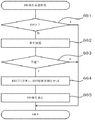
Next, the effect control processing when the
[0124]
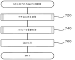
Next, an effect control process performed after all reels have stopped will be described. FIG. 30 is a flowchart showing an effect control process at the time of finishing one game. First, the
[0125]
FIG. 31 is a flowchart showing the announcement effect generation processing. First, the
[0126]
FIG. 32 is a diagram showing a flowchart showing the parameter update processing. First, the
[0127]
In the present embodiment, the ST period has been described as a situation that is advantageous to the player caused by accomplishing the task. A winning flag may be established, or the internal winning probability of a winning combination may be increased.
[0128]
In addition, the present invention provides, in addition to the slot machine as in the above-described embodiment, a pachinko game machine and an arcade game machine equipped with an electric display device, and a home game that simulates the above-described functions on software. Can be applied in the same manner.
[0129]
【The invention's effect】
According to the present invention, the electronic shutter is operated in a state in which all the reels are stopped, so that the electronic shutter can be operated over the entire display panel without taking into account the obstruction of pushing, which is a problem of the electronic shutter control during the rotation of the reel. Since the shutter can be controlled to be in the shielding state, it is possible to execute a large and clear image effect.
[Brief description of the drawings]
FIG. 1 is a perspective view showing the appearance of a pachislot gaming machine according to an embodiment.
FIG. 2 is a sectional view of a panel display unit.
FIG. 3 is a front view of a panel display unit.
FIG. 4 is a block diagram showing a main control circuit.
FIG. 5 is a block diagram showing a sub control circuit.
FIG. 6 is a view showing a winning line.
FIG. 7 is a diagram showing a reel and a back lamp.
FIG. 8 is a view showing a symbol row displayed on the outer peripheral surface of the reel.
FIG. 9 is a view showing a symbol combination and a payout number of each winning combination.
FIG. 10 is a diagram showing a stop table selected at the time of winning inside a winning combination bell.
FIG. 11 shows a winning probability table.
FIG. 12 is a view showing a list of commands transmitted to a sub control circuit.
FIG. 13 is an enlarged view of a panel display unit.
FIG. 14 is an enlarged view of a panel display unit.
FIG. 15 is a view showing an effect screen during an ST game.
FIG. 16 is a view showing an effect screen during an ST game.
FIG. 17 is a view showing a notice effect screen.
FIG. 18 is a view showing a notice effect image D side.
FIG. 19 is a diagram showing an announcement effect generation table and an effect type selection table.
FIG. 20 is a view showing a BR occurrence and BR continuation number lottery table.
FIG. 21 is a flowchart illustrating processing of a main control circuit.
FIG. 22 is a flowchart showing processing of a main control circuit.
FIG. 23 is a flowchart showing the processing of the main control circuit.
FIG. 24 is a flowchart showing “interrupt
FIG. 25 is a flowchart showing a sub-side main flow.
FIG. 26 is a flowchart showing an effect control process at the time of start.
FIG. 27 is a flowchart showing a BR occurrence lottery process.
FIG. 28 is a flowchart showing BR execution processing.
FIG. 29 is a flowchart showing an effect control process when the reel is stopped.
FIG. 30 is a flowchart showing an effect control process at the end of one game.
FIG. 31 is a flowchart showing a notice effect production process.
FIG. 32 is a flowchart showing a parameter update process.
[Explanation of symbols]
DESCRIPTION OF
104 ROM
105 RAM
106 Clock
204 sub ROM
205 sub RAM
206 Sub microcomputer IN
252 image control ROM
253 Image control RAM
254 Image IC
255 image ROM
256 video RAM
257 Image control circuit IN
Claims (3)
Priority Applications (2)
| Application Number | Priority Date | Filing Date | Title |
|---|---|---|---|
| JP2002240707A JP2004073654A (en) | 2002-08-21 | 2002-08-21 | Game machine |
| US10/697,256 US7465228B2 (en) | 2002-08-21 | 2003-10-31 | Gaming machine having a stop order associated with a prize-winning combination |
Applications Claiming Priority (1)
| Application Number | Priority Date | Filing Date | Title |
|---|---|---|---|
| JP2002240707A JP2004073654A (en) | 2002-08-21 | 2002-08-21 | Game machine |
Publications (2)
| Publication Number | Publication Date |
|---|---|
| JP2004073654A true JP2004073654A (en) | 2004-03-11 |
| JP2004073654A5 JP2004073654A5 (en) | 2005-07-28 |
Family
ID=32023421
Family Applications (1)
| Application Number | Title | Priority Date | Filing Date |
|---|---|---|---|
| JP2002240707A Pending JP2004073654A (en) | 2002-08-21 | 2002-08-21 | Game machine |
Country Status (1)
| Country | Link |
|---|---|
| JP (1) | JP2004073654A (en) |
Cited By (5)
| Publication number | Priority date | Publication date | Assignee | Title |
|---|---|---|---|---|
| JP2006296667A (en) * | 2005-04-19 | 2006-11-02 | Aruze Corp | Game performance system and server for game |
| JP2009045293A (en) * | 2007-08-21 | 2009-03-05 | Sankyo Co Ltd | Slot machine |
| US8355094B2 (en) | 2008-04-11 | 2013-01-15 | Sharp Kabushiki Kaisha | Liquid crystal display unit and gaming device |
| US8654065B2 (en) | 2008-03-26 | 2014-02-18 | Sharp Kabushiki Kaisha | Liquid crystal display unit, control method for liquid crystal display unit, and gaming device |
| US9886822B2 (en) | 2012-07-03 | 2018-02-06 | Aristocrat Technologies Australia Pty Limited | Gaming system and a method of gaming |
-
2002
- 2002-08-21 JP JP2002240707A patent/JP2004073654A/en active Pending
Cited By (5)
| Publication number | Priority date | Publication date | Assignee | Title |
|---|---|---|---|---|
| JP2006296667A (en) * | 2005-04-19 | 2006-11-02 | Aruze Corp | Game performance system and server for game |
| JP2009045293A (en) * | 2007-08-21 | 2009-03-05 | Sankyo Co Ltd | Slot machine |
| US8654065B2 (en) | 2008-03-26 | 2014-02-18 | Sharp Kabushiki Kaisha | Liquid crystal display unit, control method for liquid crystal display unit, and gaming device |
| US8355094B2 (en) | 2008-04-11 | 2013-01-15 | Sharp Kabushiki Kaisha | Liquid crystal display unit and gaming device |
| US9886822B2 (en) | 2012-07-03 | 2018-02-06 | Aristocrat Technologies Australia Pty Limited | Gaming system and a method of gaming |
Similar Documents
| Publication | Publication Date | Title |
|---|---|---|
| JP2004073651A (en) | Game machine | |
| US7465228B2 (en) | Gaming machine having a stop order associated with a prize-winning combination | |
| JP2004166880A (en) | Game machine | |
| JP2004166879A (en) | Game machine | |
| JP2004242879A (en) | Game machine | |
| US7510476B2 (en) | Gaming machine with a display controller for alternatively executing an effect and displaying a first game or alternatively executing the effect and a second game | |
| US7972206B2 (en) | Gaming machine and display device therefor | |
| US20040209671A1 (en) | Gaming machine | |
| JP2009005934A (en) | Game machine | |
| JP2005334460A (en) | Game machine | |
| JP2005161096A (en) | Game machine | |
| JP4445485B2 (en) | Game machine | |
| JP2004073653A (en) | Game machine | |
| JP2004073654A (en) | Game machine | |
| JP2004073656A (en) | Game machine | |
| JP2004073655A (en) | Game machine | |
| JP2009055962A (en) | Game machine | |
| EP1528515A1 (en) | Gaming machine | |
| JP2007151715A (en) | Game machine | |
| JP2004290515A (en) | Game machine | |
| JP2004073652A (en) | Game machine | |
| JP2007295963A (en) | Game machine | |
| JP2007037911A (en) | Game machine | |
| JP2007289412A (en) | Game machine | |
| JP2004290514A (en) | Game machine |
Legal Events
| Date | Code | Title | Description |
|---|---|---|---|
| A977 | Report on retrieval |
Free format text: JAPANESE INTERMEDIATE CODE: A971007 Effective date: 20040806 |
|
| A521 | Written amendment |
Free format text: JAPANESE INTERMEDIATE CODE: A523 Effective date: 20041210 |
|
| A871 | Explanation of circumstances concerning accelerated examination |
Free format text: JAPANESE INTERMEDIATE CODE: A871 Effective date: 20041210 |
|
| A975 | Report on accelerated examination |
Free format text: JAPANESE INTERMEDIATE CODE: A971005 Effective date: 20050104 |
|
| A131 | Notification of reasons for refusal |
Free format text: JAPANESE INTERMEDIATE CODE: A131 Effective date: 20050111 |
|
| A521 | Written amendment |
Free format text: JAPANESE INTERMEDIATE CODE: A523 Effective date: 20050314 |
|
| A02 | Decision of refusal |
Free format text: JAPANESE INTERMEDIATE CODE: A02 Effective date: 20050802 |
|
| A521 | Written amendment |
Free format text: JAPANESE INTERMEDIATE CODE: A523 Effective date: 20100528 |