EP1424559A1 - Micro flow passage device, connection device, and method of using the devices - Google Patents
Micro flow passage device, connection device, and method of using the devices Download PDFInfo
- Publication number
- EP1424559A1 EP1424559A1 EP02736206A EP02736206A EP1424559A1 EP 1424559 A1 EP1424559 A1 EP 1424559A1 EP 02736206 A EP02736206 A EP 02736206A EP 02736206 A EP02736206 A EP 02736206A EP 1424559 A1 EP1424559 A1 EP 1424559A1
- Authority
- EP
- European Patent Office
- Prior art keywords
- flow channel
- elastomer
- minute flow
- channel device
- substrate
- Prior art date
- Legal status (The legal status is an assumption and is not a legal conclusion. Google has not performed a legal analysis and makes no representation as to the accuracy of the status listed.)
- Withdrawn
Links
Images




Classifications
-
- B—PERFORMING OPERATIONS; TRANSPORTING
- B01—PHYSICAL OR CHEMICAL PROCESSES OR APPARATUS IN GENERAL
- B01L—CHEMICAL OR PHYSICAL LABORATORY APPARATUS FOR GENERAL USE
- B01L3/00—Containers or dishes for laboratory use, e.g. laboratory glassware; Droppers
- B01L3/50—Containers for the purpose of retaining a material to be analysed, e.g. test tubes
- B01L3/502—Containers for the purpose of retaining a material to be analysed, e.g. test tubes with fluid transport, e.g. in multi-compartment structures
- B01L3/5027—Containers for the purpose of retaining a material to be analysed, e.g. test tubes with fluid transport, e.g. in multi-compartment structures by integrated microfluidic structures, i.e. dimensions of channels and chambers are such that surface tension forces are important, e.g. lab-on-a-chip
- B01L3/502715—Containers for the purpose of retaining a material to be analysed, e.g. test tubes with fluid transport, e.g. in multi-compartment structures by integrated microfluidic structures, i.e. dimensions of channels and chambers are such that surface tension forces are important, e.g. lab-on-a-chip characterised by interfacing components, e.g. fluidic, electrical, optical or mechanical interfaces
-
- B—PERFORMING OPERATIONS; TRANSPORTING
- B01—PHYSICAL OR CHEMICAL PROCESSES OR APPARATUS IN GENERAL
- B01J—CHEMICAL OR PHYSICAL PROCESSES, e.g. CATALYSIS OR COLLOID CHEMISTRY; THEIR RELEVANT APPARATUS
- B01J19/00—Chemical, physical or physico-chemical processes in general; Their relevant apparatus
- B01J19/0093—Microreactors, e.g. miniaturised or microfabricated reactors
-
- B—PERFORMING OPERATIONS; TRANSPORTING
- B01—PHYSICAL OR CHEMICAL PROCESSES OR APPARATUS IN GENERAL
- B01J—CHEMICAL OR PHYSICAL PROCESSES, e.g. CATALYSIS OR COLLOID CHEMISTRY; THEIR RELEVANT APPARATUS
- B01J2219/00—Chemical, physical or physico-chemical processes in general; Their relevant apparatus
- B01J2219/00781—Aspects relating to microreactors
- B01J2219/00783—Laminate assemblies, i.e. the reactor comprising a stack of plates
-
- B—PERFORMING OPERATIONS; TRANSPORTING
- B01—PHYSICAL OR CHEMICAL PROCESSES OR APPARATUS IN GENERAL
- B01J—CHEMICAL OR PHYSICAL PROCESSES, e.g. CATALYSIS OR COLLOID CHEMISTRY; THEIR RELEVANT APPARATUS
- B01J2219/00—Chemical, physical or physico-chemical processes in general; Their relevant apparatus
- B01J2219/00781—Aspects relating to microreactors
- B01J2219/00801—Means to assemble
- B01J2219/0081—Plurality of modules
- B01J2219/00813—Fluidic connections
-
- B—PERFORMING OPERATIONS; TRANSPORTING
- B01—PHYSICAL OR CHEMICAL PROCESSES OR APPARATUS IN GENERAL
- B01J—CHEMICAL OR PHYSICAL PROCESSES, e.g. CATALYSIS OR COLLOID CHEMISTRY; THEIR RELEVANT APPARATUS
- B01J2219/00—Chemical, physical or physico-chemical processes in general; Their relevant apparatus
- B01J2219/00781—Aspects relating to microreactors
- B01J2219/00819—Materials of construction
- B01J2219/00824—Ceramic
- B01J2219/00828—Silicon wafers or plates
-
- B—PERFORMING OPERATIONS; TRANSPORTING
- B01—PHYSICAL OR CHEMICAL PROCESSES OR APPARATUS IN GENERAL
- B01J—CHEMICAL OR PHYSICAL PROCESSES, e.g. CATALYSIS OR COLLOID CHEMISTRY; THEIR RELEVANT APPARATUS
- B01J2219/00—Chemical, physical or physico-chemical processes in general; Their relevant apparatus
- B01J2219/00781—Aspects relating to microreactors
- B01J2219/00819—Materials of construction
- B01J2219/00831—Glass
-
- B—PERFORMING OPERATIONS; TRANSPORTING
- B01—PHYSICAL OR CHEMICAL PROCESSES OR APPARATUS IN GENERAL
- B01J—CHEMICAL OR PHYSICAL PROCESSES, e.g. CATALYSIS OR COLLOID CHEMISTRY; THEIR RELEVANT APPARATUS
- B01J2219/00—Chemical, physical or physico-chemical processes in general; Their relevant apparatus
- B01J2219/00781—Aspects relating to microreactors
- B01J2219/00819—Materials of construction
- B01J2219/00833—Plastic
-
- B—PERFORMING OPERATIONS; TRANSPORTING
- B01—PHYSICAL OR CHEMICAL PROCESSES OR APPARATUS IN GENERAL
- B01J—CHEMICAL OR PHYSICAL PROCESSES, e.g. CATALYSIS OR COLLOID CHEMISTRY; THEIR RELEVANT APPARATUS
- B01J2219/00—Chemical, physical or physico-chemical processes in general; Their relevant apparatus
- B01J2219/00781—Aspects relating to microreactors
- B01J2219/00891—Feeding or evacuation
-
- B—PERFORMING OPERATIONS; TRANSPORTING
- B01—PHYSICAL OR CHEMICAL PROCESSES OR APPARATUS IN GENERAL
- B01L—CHEMICAL OR PHYSICAL LABORATORY APPARATUS FOR GENERAL USE
- B01L2200/00—Solutions for specific problems relating to chemical or physical laboratory apparatus
- B01L2200/02—Adapting objects or devices to another
- B01L2200/026—Fluid interfacing between devices or objects, e.g. connectors, inlet details
-
- B—PERFORMING OPERATIONS; TRANSPORTING
- B01—PHYSICAL OR CHEMICAL PROCESSES OR APPARATUS IN GENERAL
- B01L—CHEMICAL OR PHYSICAL LABORATORY APPARATUS FOR GENERAL USE
- B01L2200/00—Solutions for specific problems relating to chemical or physical laboratory apparatus
- B01L2200/02—Adapting objects or devices to another
- B01L2200/026—Fluid interfacing between devices or objects, e.g. connectors, inlet details
- B01L2200/027—Fluid interfacing between devices or objects, e.g. connectors, inlet details for microfluidic devices
-
- B—PERFORMING OPERATIONS; TRANSPORTING
- B01—PHYSICAL OR CHEMICAL PROCESSES OR APPARATUS IN GENERAL
- B01L—CHEMICAL OR PHYSICAL LABORATORY APPARATUS FOR GENERAL USE
- B01L2200/00—Solutions for specific problems relating to chemical or physical laboratory apparatus
- B01L2200/06—Fluid handling related problems
- B01L2200/0689—Sealing
-
- B—PERFORMING OPERATIONS; TRANSPORTING
- B01—PHYSICAL OR CHEMICAL PROCESSES OR APPARATUS IN GENERAL
- B01L—CHEMICAL OR PHYSICAL LABORATORY APPARATUS FOR GENERAL USE
- B01L2200/00—Solutions for specific problems relating to chemical or physical laboratory apparatus
- B01L2200/12—Specific details about manufacturing devices
-
- B—PERFORMING OPERATIONS; TRANSPORTING
- B01—PHYSICAL OR CHEMICAL PROCESSES OR APPARATUS IN GENERAL
- B01L—CHEMICAL OR PHYSICAL LABORATORY APPARATUS FOR GENERAL USE
- B01L2300/00—Additional constructional details
- B01L2300/12—Specific details about materials
- B01L2300/123—Flexible; Elastomeric
-
- B—PERFORMING OPERATIONS; TRANSPORTING
- B01—PHYSICAL OR CHEMICAL PROCESSES OR APPARATUS IN GENERAL
- B01L—CHEMICAL OR PHYSICAL LABORATORY APPARATUS FOR GENERAL USE
- B01L3/00—Containers or dishes for laboratory use, e.g. laboratory glassware; Droppers
- B01L3/50—Containers for the purpose of retaining a material to be analysed, e.g. test tubes
- B01L3/502—Containers for the purpose of retaining a material to be analysed, e.g. test tubes with fluid transport, e.g. in multi-compartment structures
- B01L3/5027—Containers for the purpose of retaining a material to be analysed, e.g. test tubes with fluid transport, e.g. in multi-compartment structures by integrated microfluidic structures, i.e. dimensions of channels and chambers are such that surface tension forces are important, e.g. lab-on-a-chip
- B01L3/502707—Containers for the purpose of retaining a material to be analysed, e.g. test tubes with fluid transport, e.g. in multi-compartment structures by integrated microfluidic structures, i.e. dimensions of channels and chambers are such that surface tension forces are important, e.g. lab-on-a-chip characterised by the manufacture of the container or its components
Definitions
- This invention relates to a minute flow channel device with a minute flow channel, a joining device which is joined with the minute flow channel device for injecting and discharging a substance such as fluid or gas in and out of the minute flow channel of the minute flow channel device, and a method for using the minute flow channel device.
- Such a minute flow channel device and such a joining device as mentioned above are exemplified in "NOVEL INTERCONNECTION AND CHANNEL TECHNOLOGYIES FOR MICROFLUIDICS", N. J. Mourlas et al., Proceedings of the ⁇ TAS'98 Workshop (Document 1), where a plurality of openings are formed at a minute flow channel device to be functioned as inlets and outlets of a minute flow channel device which are communicated with the flow channels of the minute flow channel device, and minute pipes made of resin or metal are adhered to or pressed into the respective openings to inject and discharge fluids, etc., into and out of the respective flow channels via the respective openings and the respective pipes (first conventional example).
- FIG. 1 Another minute flow channel device and another joining device are exemplified in Document 1, where a plurality of openings are formed at a minute flow channel device to be functioned as inlets and outlets of a minute flow channel device which are communicated with the flow channels of the minute flow channel device, and gasket layers made of SiC or the like are formed around the respective openings, and fitting couplers made of plastic material are inserted into different through-holes of the minute flow channel device from the inlets and the outlets thereof to be fixed at the forefronts of the fitting couplers through thermal adhesion so that the through-holes are matched with the inlets and the outlets, and minute pipes are pressed into the respective fitting couplers to inject and discharge fluids, etc., into and out of the respective flow channels via the respective fitting couplers and the respective pipes (second conventional example).
- this applicant proposed a minute flow channel device in Japanese Patent Application Laid-open No. 2001-136963, where some joints with tubes joined therewith made of elastomer such as rubber are employed, and the through-holes communicated with the tubes of the joints are formed convexly to be pressed against the inlets and the outlets communicated with the flow channels of the minute flow channel device and to inject and discharge fluids, etc., into and out of the respective flow channels via the respective tubes (third conventional example).
- the fitting couplers and the joints are employed to increase the number of parts to be utilized for joining the pipes with the minute flow channel device, so that it is required to assure the reliability of each parts and the fabrication of the minute flow channel device may becomes complicated. Therefore, the productivity of the minute flow channel device may be degraded and the production cost of the minute flow channel device may be increased, as the first conventional example.
- the fitting couplers and the joints are joined with the respective openings once again to increase the exchange period of time, as the first conventional example.
- this invention is characterized by the following items.
- the three-dimensional processing in the flow channel and the two-dimensional processing in the flat surface can be performed simultaneously, so that the product creating operation and the product processing operation can be easily performed simultaneously under optical condition, which was not able to be performed conventionally. Therefore, the processing performance and the operationality can be enhanced in comparison with conventional ones.
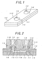
- Figs. 1 and 2 relate to a first embodiment according to the present invention.
- Fig. 1 is a perspective view illustrating a minute flow channel device relating to the first embodiment
- Fig. 2 is a cross sectional view illustrating the combination of the minute flow channel device illustrated in Fig. 1 and a joining device which is joined with the minute flow channel device.
- the illustrated minute flow channel device includes a substrate 1-1 and an elastomer 1-2 which are bonded each other.
- a ditch to constitute a flow channel are formed at either or both of the bonded surfaces of the substrate 1-1 and the elastomer 1-2.
- a ditch 1-14 is formed at the bonded surface of the elastomer 1-2 to constitute a flow channel 1-3, and through-holes are formed so as to be communicated with the flow channel 1-3 to constitute inlet 1-6 and outlet 1-7 for a substance such as fluid or gas.
- convex joints 1-4 are formed around the inlet 1-6 and the outlet 1-7 with the integration with the elastomer 1-2.
- the inclination angle ⁇ 1 of the inclined side walls 1-12 of the joints 1-4 is set to not less than 45 degrees and less than 90 degrees against the main surface of the elastomer 1-2.
- the joining device for injecting and discharging in and out of the minute flow channel device is made of a rigid member 1-5, as shown in Fig. 2, where openings 1-8 and 1-9 corresponding to the inlet 1-6 and outlet 1-7 are formed, and concave joint matching members 1-10 are formed at the joining regions between the minute flow channel device and the joining device so as to surround the openings 1-8 and 1-9.
- the size of the joint matching member 1-10 is set smaller than the size of the convex joint 1-4.
- the edges 1-11 of the inner walls of the joint matching members 1-10 is contacted with the peripheries of the inclined side walls 1-12 of the convex joints 1-4 to join the rigid member 1-5, that is, the joining device with the minute flow channel device.
- the minute flow channel device and the joining device are joined each other through the pressing contact of the concave joint matching members 1-10 with the openings 1-8 and 1-9 formed at the rigid member 1-5 as the joining'device against the convex joints 1-4 with the inlet 1-6 and the outlet 1-7 formed at the elastomer 1-2 of the minute flow channel device.
- the inclination angle ⁇ 1 of the inclined side walls 1-12 of the joints 1-4 is set to not less than 45 degrees and less than 90 degrees so that the joints 1-4 are spread downward.
- the substances to be injected and discharged can be sealed precisely at the connection between the minute flow channel device and the joining device.
- the inclination angle ⁇ 1 of the inclined side walls 1-12 of the joints 1-4 is set within another angle range except the above-mentioned preferable angle range, the inclined side walls 1-12 can not be contacted with the edges 1-11 of the inner walls of the joint matching members 1-10 sufficiently, so that the sealing performance of the substance to be injected and discharged may be deteriorated. Therefore, the inclination angle ⁇ 1 is preferably set within the above-mentioned preferable angle range.
- an additional joining member such as a fitting coupler except the joining device where the inlet 1-8 and the outlet 1-9 as flow channels communicated with the flow channel 1-3 of the minute flow channel device are formed is not required, and the attachment to another device of the additional joining member is not required. Moreover, minute pipes to be pressed into the inlet 1-8 and the outlet 1-9 are not required.
- the rigid member 1-5 as the joining device can be joined easily with the minute flow channel device through pressing therebetween, so that the joining operation between the minute flow channel device and the joining device can be automatized with a given instrument. As a result, the joining operation and the joining structure can be simplified, so that the reliability of the joining operation can be developed and the joining cost can be lowered.
- the joint matching members 1-10 are formed at both of the inlet 1-8 and the outlet 1-9 of the rigid member 5 as the joining device, but may be formed at another pipe-shaped rigid member.
- the ditch 1-4 is formed at the elastomer 1-2 to constitute the flow channel 1-3.
- another ditch may be formed at the substrate 1-1 to constitute another flow channel.
- ditches may be formed at the substrate 1-1 and the elastomer 1-2 so as to be matched each other to constitute a flow channel. In these cases, the same function and effect as this embodiment can be exhibited.
- the elastomer 1-2 may be made of sticky material with the substrate 1-1.
- the substrate 1-1 and the elastomer 1-2 can be joined each other without any adhesive to form the flow channel. Therefore, the joining operation can be much simplified, and the inclined side walls 1-12 can be tightly contacted with the edges 1-11 of the inner walls of the joint matching members 1-10.
- the sticky material can be exemplified silicon rubber, particularly polydimethylsiloxane with excellent adhesive.
- silicon rubber enables the minute flow channel device and the joining device to be easily and tightly joined.
- silicon rubber silicon RVT rubber KE-1310ST for mold patterning (which is trade name and made by Shin-Etsu Chemical Co. Ltd.) may be preferably employed.
- the elastomer 1-2 can be exchanged by another elastomer after the use of the minute flow channel device for a given period. Therefore, the contamination of the minute flow channel device by substances to be injected and discharged can be reduced. Moreover, since the elastomer 1-2 can be washed with separation from the substrate 1-1, the minute flow channel device can be easily reused, so that some components of the minute flow channel device can not be wasted after the use for a given period of time. In addition, if various elastomers with respective various ditches are prepared, various minute flow channel device can be fabricated in low cost.
- the preferable joining device and joining method can be provided, whereby a substance such as fluid or gas can be introduced into the minute flow channel device from outside and which are usable as a joining device and a joining method for a DNA capillary array as the minute flow channel device.
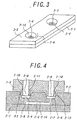
- Figs. 3 and 4 relate to a second embodiment according to the present invention.
- Fig. 3 is a perspective view illustrating a minute flow channel device relating to the second embodiment
- Fig. 4 is a cross sectional view illustrating the combination of the minute flow channel device illustrated in Fig. 3 and a joining device which is joined with the minute flow channel device.
- the illustrated minute flow channel device includes a substrate 2-1 and an elastomer 2-2 which are bonded each other, as the first embodiment.
- a ditch 2-14 is formed at the bonded surface of the elastomer 2-2 to constitute a flow channel 2-3, and through-holes are formed so as to be communicated with the flow channel 2-3 to constitute inlet 2-6 and outlet 2-7 for a substance such as fluid or gas.
- concave joints 2-4 are formed around the inlet 2-6 and the outlet 2-7 with the integration with the elastomer 2-2, different from the first embodiment.
- the inclination angle ⁇ 2 of the inclined side walls 2-12 of the joints 2-4 is set to not less than 45 degrees and less than 90 degrees against the main surface of the elastomer 2-2.
- the joining device is made of a rigid member 2-5, where openings 2-8 and 2-9 corresponding to the inlet 2-6 and outlet 2-7 are formed, and convex joint matching member 2-10 are formed at the joining regions between the minute flow channel device and the joining device so as to surround the openings 2-8 and 2-9.
- the size of the joint matching member 2-10 is set smaller than the size of the concave joint 2-4.
- the edges 2-11 of the inner walls of the joint matching members 2-10 is contacted with the peripheries of the inclined side walls 2-12 of the concave joints 2-4 to join the rigid member 2-5, that is, the joining device with the minute flow channel device.
- the minute flow channel device and the joining device are joined each other through the pressing contact of the convex joint matching member 2-10 against the concave joints 2-4, so that the same function/effect as the first embodiment can be exhibited.
- the top surface of the elastomer 2-2 can be flattened, so that there can not be almost the conveying error of the minute flow channel device and the operationality of the minute flow channel device can be developed.
- the joint matching members 2-10 which are formed at both of the inlet 2-8 and the outlet 2-9 may be formed at another pipe-shaped rigid member.
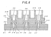
- Figs. 5 through 7 relate to a third embodiment according to the present invention.
- Fig. 5 is a perspective view illustrating a minute flow channel device relating to the third embodiment
- Fig. 6 is a cross sectional view illustrating the combination of the minute flow channel device illustrated in Fig. 5 and a joining device which is joined with the minute flow channel device.
- Fig. 7 is a perspective view illustrating components of the combination illustrated in Fig. 5.
- Figs. 7(a) and (b) are perspective views illustrating the joining device and the minute flow channel device, respectively
- Figs. 7(c) and (d) are perspective views illustrating the elastomer and the substrate of the minute flow channel device, respectively.
- FIG. 7(b) is constructed of the substrate 3-1 illustrated in Fig. 7(d) and the elastomer 3-2 illustrated in Fig. 7(c) which are bonded each other.
- the combination illustrated in Figs. 5 and 6 is constructed of the minute flow channel device illustrated in Fig. 7(b) and the joining device illustrated in Fig. 7(a) which are joined through pressing therebetween.
- This embodiment is a modification from the first embodiment, so the essence of the present embodiment will be described.
- the illustrated minute flow channel device includes a substrate 3-1 which is disposed in the lower side and an elastomer 3-2 which is disposed in the upper side.
- the elastomer 3-2 functions as a covering member for the substrate 3-1 as illustrated in Figs. 5, 6, 7(b) and 7(c), and thus, made of polydimethylsiloxane (PDMS) by means of integral molding using a die.
- PDMS polydimethylsiloxane
- At the elastomer 3-2 are formed a suspension inlet 3-6 to inject suspension and five outlets 3-7 to collect the suspension after processing so as to be through the elastomer 3-2.
- convex joints 3-4 are formed around the inlet 3-6 and the outlets 3-7 with integration with the elastomer 3-2.
- the rear surface of the elastomer 3-2 opposite to the main surface where convex joints 3-4 are formed is smoothed.
- the substrate 3-1 may be made of silicon. Ditches 3-14 are formed at the bonded surface of the substrate 3-1 to constitute flow channels 3-3, as illustrated in Fig. 6 and Fig. 7(d).
- the substrate 3-1 and the elastomer 3-2 are bonded each other by bonding the main surface with the ditches 3-14 and the rear surface of the elastomer 3-2 with adhesive PDMS to constitute the minute flow channel device. That is, the components illustrated in Figs. 7 (c) and (d) are bonded vertically to constitute the minute flow channel device illustrated in Fig. 7(b).
- the joining device is made of a rigid member such as aluminum member, as illustrated in Fig. 5, 6 and 7(a), where openings 3-8 and 3-9 corresponding to the inlet 3-6 and outlets 3-7 are formed, and concave joint matching member 3-10 are formed at the rear surface of the rigid member 3-5. Then, tubes 3-15 for injecting and discharging are joined with the joint matching members 3-10 so as to be communicated with the openings 3-8 and 3-9. In Figs. 5, 6 and 7(a), the non-joined sides (forefronts) of the tubes 3-15 are cut off.
- the joining member can be pressed against and joined with the minute flow channel device so that the joint matching members 3-10 are matched to the joints 3-4 and the edges 3-11 of the inner walls of the joint matching members 3-10 are pressed against the peripheries of the inclined side walls 3-12 of the joints 3-4. That is, in Fig. 7, the components illustrated in Figs. 7(a) and (b) are joined vertically to constitute the combination illustrated in Figs. 5 and 6.
- the same function/effect as the first and the second embodiments can be exhibited.
- the (six) joint matching members 3-10 formed at the rigid member 3-5 are joined with the (six) joints 3-4 on the block, so that the joining operation can be automatized easily.
- the elastomer 3-2 is made of PDMS with excellent adhesive and elasticity, the connections between the edges 3-11 of the joint matching members 3-10 and the joints 3-4 can be sealed precisely by utilizing the adhesive and the elasticity of the PDMS.
- This embodiment may be modified and varied.
- the number of the joint 3-4 is not limited to six as illustrated in this embodiment, but to any number requiring in the combination.
- the joint matching members 3-10 corresponding to the respective joints 3-4 may be formed at a plurality of rigid members.
- the substrate 3-1 may be made of glass or fused silica, in addition to silicon, and the elastomer 3-2 may be made of any other elastic material such as latex, in addition to the PDMS.
- the flow channel may be formed by various patterns, and the ditches may be formed at the elastomer 3-2 and both of the substrate 3-1 and the elastomer 3-2, in addition to the substrate 3-1.
- the combination can function as a reactor.
- the regent may be disposed at either of elastomer and substrate. In this case, after reaction, either of the elastomer and substrate is exchanged. Therefore, the minute flow channel device can be reused through the exchange and the component of the minute flow channel device is not wasted.
- the present modification can be applied for the first and the second embodiments.
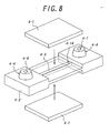
- Fig. 8 is an exploded perspective view illustrating substantial parts of a fourth embodiment relating to a minute flow channel device according to the present invention.
- a ditch 4-14 of an elastomer 4-2 is partially bored, and then, the elastomer 4-2 is sandwiched by two substrates 4-1 to constitute a flow channel 4-3.
- the substrates 4-1 are preferably made of optically transparent material. In this case, external observation or optically measurement can be carried out easily.
- reference numeral 4-4 designates joints
- reference numeral 4-6 and 4-7 designate an inlet and an outlet, respectively.
- Figs. 9 through 11 relate to a fifth embodiment according to the present invention.
- Fig. 9 is a perspective view illustrating the combination of a minute flow channel device relating to the fifth embodiment and a joining device which is joined with the minute flow channel device
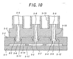
- Fig. 10 is a cross sectional view illustrating the combination illustrated in Fig. 9.
- Fig. 11 is a perspective view illustrating components of the combination illustrated in Fig. 9.
- Figs. 11(a) and (b) are perspective views illustrating the joining device and the minute flow channel device, respectively
- Figs. 11(c) and (d) are perspective views illustrating the elastomer as viewed from the top side and the bottom side, respectively.
- FIG. 11(b) is constructed of the substrate 5-1 and the elastomer 5-2 illustrated in Figs. 11(c) and (d) which are bonded each other.
- the combination illustrated in Figs. 9 and 10 is constructed of the minute flow channel device illustrated in Fig. 11(b) and the joining device illustrated in Fig. 11(a) which are joined through pressing therebetween.
- This embodiment is a modification from the second embodiment, so the essence of the present embodiment will be described because the fundamental structure of the present embodiment is similar to the one of the second embodiment.
- the illustrated minute flow channel device includes a substrate 5-1 which is disposed in the lower side and an elastomer 5-2 which is disposed in the upper side.
- the elastomer 5-2 functions as a covering member for the substrate 5-1 as illustrated in Figs. 9, 10, 11(b) through 11(d), and thus, made of polydimethylsiloxane (PDMS) by means of integral molding using a die.
- PDMS polydimethylsiloxane
- At the elastomer 5-2 are formed a suspension inlet 5-16 to inject suspension and three outlets 5-6 and 5-7 to collect the suspension after processing so as to be through the elastomer 5-2.
- concave joints 5-4 are formed around the inlet 5-16 and the outlets 5-6; 5-7 with integration with the elastomer 5-2 at the main surface to be joined. Then, at the rear surface of the elastomer 5-2 is formed a ditch 5-14 to constitute a flow channel 5-3 as illustrated in Fig. 11(d). Then, at the ditch 5-14 are formed pillars 5-17.
- the substrate 5-1 may be made of flat glass, as illustrated in Fig. 10.
- the substrate 5-1 and the elastomer 5-2 are bonded each other with adhesive PDMS to constitute the minute flow channel device.
- the joining device is made of a rigid member such as aluminum member, as illustrated in Fig. 9, 10 and 11(a), where openings 5-8 and 5-9 communicated with the inlet 5-16 and the outlets 5-6; 5-7 are formed, and tubes 5-18 to constitute joint matching members 5-10 are formed at the rear surface of the rigid member 5-5, and tubes 5-15 for injecting and discharging are formed at the main surface of the rigid member 5-5.
- Figs. 9, 10 and 11(a) the non-joined sides (forefronts) of the tubes 5-15 are cut off.
- the joining member can be pressed against and joined with the minute flow channel device so that the joint matching members 5-10 are matched to the joints 5-4 and the edges 5-11 of the inner walls of the joint matching members 5-10 are pressed against the peripheries of the inclined side walls 5-12 of the joints 5-4. That is, in Fig. 11, the components illustrated in Figs. 11(a) and (b) are joined vertically to constitute the combination illustrated in Figs. 9 and 10.
- Fig. 10 is a lateral cross section of the combination between the minute flow channel device and the joining device, where three outlets 5-6 and 5-7 are arranged laterally.
- the minute flow channel device can be utilized as a DNA chip where many DNA probes are immobilized.
- the DNA probes are immobilized at the flow channel of the substrate. Since the substrate is flat, the solidification of the DNA probes can be performed by means of normal solidification such as spotting method, point solidification method using ink jet method or optical solidification method using optical reaction.
- the elastomer is bonded with the substrate to constitute the minute flow channel device by utilizing the adhesion of the elastomer.
- the elastomer is made of silicone resin, the connection between the substrate and the elastomer can be sealed sufficiently not to leak fluid, and the elastomer can be easily deformed by the pressing at the joint between the substrate and the elastomer. Therefore, the silicone resin elastomer can be preferably employed.
- the minute flow channel device can be employed for liquid processing such as chemical reaction, extraction or flow channel washing. Since the substrate can be detached from the elastomer after the liquid processing, the substrate with the immobilized DNA probes therein can be measured by a measuring device commercially available.
- a liquid sample containing nucleic acid to be measured is injected into the flow channel 1-3 or 2-3 as illustrated in Figs. 1-4 to create a product through the nucleic acid hybridization reaction in the flow channel.
- a liquid reagent containing a nucleic probe to be reacted with the targeting nucleic acid in the liquid sample is injected simultaneously or successively.
- the injecting pressure and the discharging pressure are controlled appropriately so that the liquid sample is pumped in the flow channel, the chemical reaction between the targeting nucleic acid and the nucleic probe. In this way, the nucleic acid hybridization reaction can be performed three-dimensionally in the flow channel.
- the elastomer 1-2 or 2-2 is detached from the substrate 1-1 or 2-1 to investigate the liquid sample remaining at the substrate or the elastomer.
- the investigation may be performed with, e.g., a fluorescence measuring device.
- the intensity of fluorescence from the liquid sample is measured.
- the measurement sensitivity can be enhanced.
- the substrate is flat, different kinds pf nucleic probes can be immobilized in high density in the flow channel of the substrate. Therefore, if the nucleic acid hybridization reaction is performed three-dimensionally and the measurement is performed two-dimensionally, the increase in reacting amount and various measurements can be performed effectively and efficiently.
- the chemical reaction and measurement using the liquid reagent can be applied for all of the embodiments as mentioned above.
- a ditch or a minute hole for holding the liquid reagent to be used in measurement is formed at the minute flow channel device.
- the chemical reaction and measurement using the immobilized reagent can be applied for all of the embodiments as mentioned above.
- the immobilized reagent is set onto the plane surface of the substrate or the elastomer as the minute flow channel device is separated into the substrate and the elastomer.
- the setting of the immobilized reagent can be performed by means of point solidification method or optical solidification method.
- the immobilized reagent is preferably set plurally in the flow channel of the minute flow channel device.
- the solidifying length can be controlled by increasing or decreasing the spotting number or the optical illumination number.
- the chemical reaction using the nucleic probe is performed two-dimensionally.
- the amount of the nucleic probe to be used in the chemical reaction is small in comparison with a three dimensional chemical reaction, and the agitation in the chemical reaction is not sufficient. As a result, the measurement sensitivity for the resultant liquid sample is deteriorated.
- the solidifying and the ditch formation of the elastomer is performed commensurate with the flow channels of the slide glass.
- a plurality of flow channels e.g., six flow channels
- the liquid processing can be performed at every flow channel without the mixing of the adjacent flow channels.
- the separation and collection of a given fluid can be applied for all of the embodiments as mentioned above.
- a substrate and an elastomer are joined each other to constitute a minute flow channel device and to perform a three-dimensional separation using the minute flow channel device.
- the three-dimensional separation means affinity chromatography, electrophoretic migration and the like. Then, the elastomer is released to easily collect the resultant product from the substrate and/or the elastomer after separation.
- the separation and collection may be carried out in a given chemical reaction.
- a given reagent is added to the fluid by means of point solidification or the like to perform a selective reaction between the fluid and the reagent, before or in place of collection. Then, after the release of the elastomer, the substrate and/or the elastomer may be washed. In this case, waste contamination can be reduced, and the substrate and/or the elastomer can be reused repeatedly.
- a composite liquid processing which is a combination of the three-dimensional liquid processing using the combination of the substrate and the elastomer and the two-dimensional liquid processing for the product created by the three-dimensional liquid processing after the release of the elastomer, can be performed.
- all of the embodiments as mentioned above can be utilized at the most.
- the use of joints can exhibit the same function/effect as the embodiments as mentioned previously. That is, since the (four) joint matching members 5-10 are formed at the same rigid member 5-5, the joint matching members 5-10 can be joined with the joints 5-4 in the block. Therefore, the joining operation can be simplified to be easily automatized. Particularly, if the elastomer 5-2 is made of PDMS with high adhesion and elasticity, the minute flow channel device can be easily fabricated and the connection between the joints 5-4 and the joint matching members 5-1 can be sealed precisely by the adhesion and elasticity of the PDMS.
- the fifth embodiment may be modified and varied.
- the number of the joint 5-4 is not limited to four as illustrated in this embodiment, but to any number requiring in the combination.
- the total number of the inlet 5-8 and the outlets 5-6; 5-7 is not limited to four as illustrated in this embodiment, but to any number requiring in the combination.
- the joint matching members 5-10 corresponding to the respective joints 5-4 may be formed at a plurality of rigid members.
- the substrate 5-1 may be made of silicon or fused silica, in addition to glass, and the elastomer 5-2 may be made of any other elastic material such as latex, in addition to the PDMS.
- the connection between the minute flow channel device and the joining device does not depend on the configuration of the flow channel of the minute flow channel device. Therefore, the configuration of the ditches 5-14 illustrated in Fig. 11(d) is exemplified and not limited.
- the ditches 5-14 may be formed at the substrate 5-1 or both of the substrate 5-1 and the elastomer 5-2.
- the convex or concave joint may be formed at the side of the elastomer, instead of the main surface thereof.
- connection to inject and discharge a substance such as fluid or gas can be easily realized and automatized. Moreover, the reliability of the connection can be developed.
- a minute flow channel device and a joining device which are to be joined under the connection as mentioned above can be provided in low cost and high productivity.
- the minute flow channel device and/or the joining device can be easily exchanged.
- a liquid processing can be performed sufficiently to create a reacted production, and a selective liquid processing can be performed for the reacted production. Therefore, the processing performance and the operationality can be developed.
Landscapes
- Chemical & Material Sciences (AREA)
- Chemical Kinetics & Catalysis (AREA)
- Health & Medical Sciences (AREA)
- Clinical Laboratory Science (AREA)
- General Health & Medical Sciences (AREA)
- Hematology (AREA)
- Analytical Chemistry (AREA)
- Dispersion Chemistry (AREA)
- Organic Chemistry (AREA)
- Physical Or Chemical Processes And Apparatus (AREA)
- Branch Pipes, Bends, And The Like (AREA)
- Sampling And Sample Adjustment (AREA)
- Apparatus Associated With Microorganisms And Enzymes (AREA)
Abstract
A substrate and an elastomer are bonded each other, and then, a ditch
is formed at the bonded surface of the substrate or the elastomer to constitute a
flow channel and thus, to constitute a minute flow channel device with the flow
channel. Then, a through-hole functioning an inlet and/or outlet is formed at the
elastomer so as to be communicated with the flow channel. Then, a convex or
concave joint is formed at the elastomer with integration so as to be opened
outward from the through-hole so that the inclination angle of said joint is set to
not less than 45 degrees and less than 90 degrees. Then, a joining device is
pressed and joined with the minute flow channel device via the joint. Therefore,
the connection for injecting and discharging a substance such as fluid or gas can
be easily realized and automatized, and the device exchange can be performed
easily.
Description
This invention relates to a minute flow channel device with a minute
flow channel, a joining device which is joined with the minute flow channel
device for injecting and discharging a substance such as fluid or gas in and out of
the minute flow channel of the minute flow channel device, and a method for
using the minute flow channel device.
For injecting and discharging a substance such as fluid or gas in and
out of a minute flow channel of a minute flow channel device, it is required to
join a joining device exclusively for injecting and discharging with the minute
flow channel device.
Such a minute flow channel device and such a joining device as
mentioned above are exemplified in "NOVEL INTERCONNECTION AND
CHANNEL TECHNOLOGYIES FOR MICROFLUIDICS", N. J. Mourlas et al.,
Proceedings of the µTAS'98 Workshop (Document 1), where a plurality of
openings are formed at a minute flow channel device to be functioned as inlets
and outlets of a minute flow channel device which are communicated with the
flow channels of the minute flow channel device, and minute pipes made of resin
or metal are adhered to or pressed into the respective openings to inject and
discharge fluids, etc., into and out of the respective flow channels via the
respective openings and the respective pipes (first conventional example).
In addition, another minute flow channel device and another joining
device are exemplified in Document 1, where a plurality of openings are formed
at a minute flow channel device to be functioned as inlets and outlets of a minute
flow channel device which are communicated with the flow channels of the
minute flow channel device, and gasket layers made of SiC or the like are formed
around the respective openings, and fitting couplers made of plastic material are
inserted into different through-holes of the minute flow channel device from the
inlets and the outlets thereof to be fixed at the forefronts of the fitting couplers
through thermal adhesion so that the through-holes are matched with the inlets
and the outlets, and minute pipes are pressed into the respective fitting couplers
to inject and discharge fluids, etc., into and out of the respective flow channels
via the respective fitting couplers and the respective pipes (second conventional
example).
Moreover, this applicant proposed a minute flow channel device in
Japanese Patent Application Laid-open No. 2001-136963, where some joints with
tubes joined therewith made of elastomer such as rubber are employed, and the
through-holes communicated with the tubes of the joints are formed convexly to
be pressed against the inlets and the outlets communicated with the flow
channels of the minute flow channel device and to inject and discharge fluids,
etc., into and out of the respective flow channels via the respective tubes (third
conventional example).
In the first conventional example, however, since the pipe pressing
and the precise pipe adhesion are required, the reliability of sealing the joint
between the pipes and the openings of the minute flow channel device are
degraded and the productivity of minute flow channel device is also degraded so
that the production cost of minute flow channel device is increased. In the
exchange of minute flow channel device, since the pipes for joint and the
external tubes are released and attached once again, it may take much times in
exchanging the minute flow channel device into another one if it is required to
join many flow channels to the pipes and the tubes. Moreover, it is difficult to
automatize the tube pressing against the pipes.
In the second and the third conventional examples, the fitting couplers
and the joints are employed to increase the number of parts to be utilized for
joining the pipes with the minute flow channel device, so that it is required to
assure the reliability of each parts and the fabrication of the minute flow channel
device may becomes complicated. Therefore, the productivity of the minute
flow channel device may be degraded and the production cost of the minute flow
channel device may be increased, as the first conventional example. In the
exchange of the minute flow channel device, the fitting couplers and the joints
are joined with the respective openings once again to increase the exchange
period of time, as the first conventional example.
It is an object of the present invention, in view of the conventional
problems, to provide a minute flow channel device and a joining device for the
minute flow channel device, whereby the joining for injecting and discharging a
substance such as fluid or gas can be automatized and performed easily to
enhance the reliability and the productivity of the minute flow channel device; to
decrease the production cost of the minute flow channel device and to simplify
the exchanging process of the minute flow channel device, and to provide a
method for using the minute flow channel device.
In view of the object of the present invention, this invention is
characterized by the following items.
In this case, the three-dimensional processing in the flow channel and
the two-dimensional processing in the flat surface can be performed simultaneously,
so that the product creating operation and the product processing operation
can be easily performed simultaneously under optical condition, which was not
able to be performed conventionally. Therefore, the processing performance
and the operationality can be enhanced in comparison with conventional ones.
For better understanding of the present invention, reference is made to
the attached drawings, wherein
Figs. 1 and 2 relate to a first embodiment according to the present
invention. Fig. 1 is a perspective view illustrating a minute flow channel device
relating to the first embodiment, and Fig. 2 is a cross sectional view illustrating
the combination of the minute flow channel device illustrated in Fig. 1 and a
joining device which is joined with the minute flow channel device.
The illustrated minute flow channel device includes a substrate 1-1
and an elastomer 1-2 which are bonded each other. A ditch to constitute a flow
channel are formed at either or both of the bonded surfaces of the substrate 1-1
and the elastomer 1-2. In this embodiment, as illustrated in Fig. 2, a ditch 1-14
is formed at the bonded surface of the elastomer 1-2 to constitute a flow channel
1-3, and through-holes are formed so as to be communicated with the flow channel
1-3 to constitute inlet 1-6 and outlet 1-7 for a substance such as fluid or gas.
Moreover, convex joints 1-4 are formed around the inlet 1-6 and the
outlet 1-7 with the integration with the elastomer 1-2. In this case, the inclination
angle 1 of the inclined side walls 1-12 of the joints 1-4 is set to not less
than 45 degrees and less than 90 degrees against the main surface of the
elastomer 1-2.
The joining device for injecting and discharging in and out of the
minute flow channel device is made of a rigid member 1-5, as shown in Fig. 2,
where openings 1-8 and 1-9 corresponding to the inlet 1-6 and outlet 1-7 are
formed, and concave joint matching members 1-10 are formed at the joining
regions between the minute flow channel device and the joining device so as to
surround the openings 1-8 and 1-9. The size of the joint matching member 1-10
is set smaller than the size of the convex joint 1-4. The edges 1-11 of the inner
walls of the joint matching members 1-10 is contacted with the peripheries of the
inclined side walls 1-12 of the convex joints 1-4 to join the rigid member 1-5,
that is, the joining device with the minute flow channel device.
In this way, in this embodiment, the minute flow channel device and
the joining device are joined each other through the pressing contact of the
concave joint matching members 1-10 with the openings 1-8 and 1-9 formed at
the rigid member 1-5 as the joining'device against the convex joints 1-4 with the
inlet 1-6 and the outlet 1-7 formed at the elastomer 1-2 of the minute flow
channel device. In this case, the inclination angle 1 of the inclined side walls
1-12 of the joints 1-4 is set to not less than 45 degrees and less than 90 degrees
so that the joints 1-4 are spread downward. Since the inclined side walls 1-12
of the joints 1-4 are deformed elastically so as to contact with the edges 1-11 of
the inner walls of the joint matching members 1-10, the substances to be injected
and discharged can be sealed precisely at the connection between the minute flow
channel device and the joining device.
Herein, if the inclination angle 1 of the inclined side walls 1-12 of
the joints 1-4 is set within another angle range except the above-mentioned
preferable angle range, the inclined side walls 1-12 can not be contacted with the
edges 1-11 of the inner walls of the joint matching members 1-10 sufficiently, so
that the sealing performance of the substance to be injected and discharged may
be deteriorated. Therefore, the inclination angle 1 is preferably set within the
above-mentioned preferable angle range.
In this embodiment, an additional joining member such as a fitting
coupler except the joining device where the inlet 1-8 and the outlet 1-9 as flow
channels communicated with the flow channel 1-3 of the minute flow channel
device are formed is not required, and the attachment to another device of the
additional joining member is not required. Moreover, minute pipes to be pressed
into the inlet 1-8 and the outlet 1-9 are not required. In this embodiment, the
rigid member 1-5 as the joining device can be joined easily with the minute flow
channel device through pressing therebetween, so that the joining operation
between the minute flow channel device and the joining device can be automatized
with a given instrument. As a result, the joining operation and the joining
structure can be simplified, so that the reliability of the joining operation can be
developed and the joining cost can be lowered.
In this embodiment, as illustrated in Fig. 2, the joint matching members
1-10 are formed at both of the inlet 1-8 and the outlet 1-9 of the rigid member 5
as the joining device, but may be formed at another pipe-shaped rigid member.
In this embodiment, the ditch 1-4 is formed at the elastomer 1-2 to
constitute the flow channel 1-3. However, another ditch may be formed at the
substrate 1-1 to constitute another flow channel. In addition, ditches may be
formed at the substrate 1-1 and the elastomer 1-2 so as to be matched each other
to constitute a flow channel. In these cases, the same function and effect as this
embodiment can be exhibited.
The elastomer 1-2 may be made of sticky material with the substrate
1-1. In this case, the substrate 1-1 and the elastomer 1-2 can be joined each other
without any adhesive to form the flow channel. Therefore, the joining operation
can be much simplified, and the inclined side walls 1-12 can be tightly contacted
with the edges 1-11 of the inner walls of the joint matching members 1-10.
As the sticky material can be exemplified silicon rubber, particularly
polydimethylsiloxane with excellent adhesive. The use of silicon rubber
enables the minute flow channel device and the joining device to be easily and
tightly joined. As the silicon rubber, silicon RVT rubber KE-1310ST for mold
patterning (which is trade name and made by Shin-Etsu Chemical Co. Ltd.) may
be preferably employed.
It is desired to bond the elastomer 1-2 with the substrate 1-1
detachably. In this case, the elastomer 1-2 can be exchanged by another
elastomer after the use of the minute flow channel device for a given period.
Therefore, the contamination of the minute flow channel device by substances to
be injected and discharged can be reduced. Moreover, since the elastomer 1-2
can be washed with separation from the substrate 1-1, the minute flow channel
device can be easily reused, so that some components of the minute flow channel
device can not be wasted after the use for a given period of time. In addition, if
various elastomers with respective various ditches are prepared, various minute
flow channel device can be fabricated in low cost.
In this embodiment, in addition to the preferable minute flow channel
device, the preferable joining device and joining method can be provided,
whereby a substance such as fluid or gas can be introduced into the minute flow
channel device from outside and which are usable as a joining device and a
joining method for a DNA capillary array as the minute flow channel device.
Figs. 3 and 4 relate to a second embodiment according to the present
invention. Fig. 3 is a perspective view illustrating a minute flow channel device
relating to the second embodiment, and Fig. 4 is a cross sectional view illustrating
the combination of the minute flow channel device illustrated in Fig. 3 and a
joining device which is joined with the minute flow channel device.
In this embodiment, the illustrated minute flow channel device
includes a substrate 2-1 and an elastomer 2-2 which are bonded each other, as the
first embodiment. A ditch 2-14 is formed at the bonded surface of the elastomer
2-2 to constitute a flow channel 2-3, and through-holes are formed so as to be
communicated with the flow channel 2-3 to constitute inlet 2-6 and outlet 2-7 for
a substance such as fluid or gas. Also, in this embodiment, concave joints 2-4
are formed around the inlet 2-6 and the outlet 2-7 with the integration with the
elastomer 2-2, different from the first embodiment. In this case, the inclination
angle 2 of the inclined side walls 2-12 of the joints 2-4 is set to not less than 45
degrees and less than 90 degrees against the main surface of the elastomer 2-2.
The joining device is made of a rigid member 2-5, where openings
2-8 and 2-9 corresponding to the inlet 2-6 and outlet 2-7 are formed, and convex
joint matching member 2-10 are formed at the joining regions between the
minute flow channel device and the joining device so as to surround the openings
2-8 and 2-9. The size of the joint matching member 2-10 is set smaller than the
size of the concave joint 2-4. The edges 2-11 of the inner walls of the joint
matching members 2-10 is contacted with the peripheries of the inclined side
walls 2-12 of the concave joints 2-4 to join the rigid member 2-5, that is, the
joining device with the minute flow channel device.
In this way, in this embodiment, the minute flow channel device and
the joining device are joined each other through the pressing contact of the
convex joint matching member 2-10 against the concave joints 2-4, so that the
same function/effect as the first embodiment can be exhibited. Moreover, the
top surface of the elastomer 2-2 can be flattened, so that there can not be almost
the conveying error of the minute flow channel device and the operationality of
the minute flow channel device can be developed.
In this embodiment, too, the joint matching members 2-10 which are
formed at both of the inlet 2-8 and the outlet 2-9 may be formed at another pipe-shaped
rigid member.
Figs. 5 through 7 relate to a third embodiment according to the
present invention. Fig. 5 is a perspective view illustrating a minute flow
channel device relating to the third embodiment, and Fig. 6 is a cross sectional
view illustrating the combination of the minute flow channel device illustrated in
Fig. 5 and a joining device which is joined with the minute flow channel device.
Fig. 7 is a perspective view illustrating components of the combination illustrated
in Fig. 5. Figs. 7(a) and (b) are perspective views illustrating the joining device
and the minute flow channel device, respectively, and Figs. 7(c) and (d) are
perspective views illustrating the elastomer and the substrate of the minute flow
channel device, respectively. The minute flow channel device illustrated in Fig.
7(b) is constructed of the substrate 3-1 illustrated in Fig. 7(d) and the elastomer
3-2 illustrated in Fig. 7(c) which are bonded each other. The combination
illustrated in Figs. 5 and 6 is constructed of the minute flow channel device
illustrated in Fig. 7(b) and the joining device illustrated in Fig. 7(a) which are
joined through pressing therebetween.
This embodiment is a modification from the first embodiment, so the
essence of the present embodiment will be described.
The illustrated minute flow channel device includes a substrate 3-1
which is disposed in the lower side and an elastomer 3-2 which is disposed in the
upper side. The elastomer 3-2 functions as a covering member for the substrate
3-1 as illustrated in Figs. 5, 6, 7(b) and 7(c), and thus, made of polydimethylsiloxane
(PDMS) by means of integral molding using a die. At the elastomer
3-2 are formed a suspension inlet 3-6 to inject suspension and five outlets 3-7 to
collect the suspension after processing so as to be through the elastomer 3-2.
Moreover, convex joints 3-4 are formed around the inlet 3-6 and the outlets 3-7
with integration with the elastomer 3-2. In this embodiment, the rear surface of
the elastomer 3-2 opposite to the main surface where convex joints 3-4 are
formed is smoothed.
The substrate 3-1 may be made of silicon. Ditches 3-14 are formed
at the bonded surface of the substrate 3-1 to constitute flow channels 3-3, as
illustrated in Fig. 6 and Fig. 7(d). The substrate 3-1 and the elastomer 3-2 are
bonded each other by bonding the main surface with the ditches 3-14 and the rear
surface of the elastomer 3-2 with adhesive PDMS to constitute the minute flow
channel device. That is, the components illustrated in Figs. 7 (c) and (d) are
bonded vertically to constitute the minute flow channel device illustrated in
Fig. 7(b).
The joining device is made of a rigid member such as aluminum
member, as illustrated in Fig. 5, 6 and 7(a), where openings 3-8 and 3-9 corresponding
to the inlet 3-6 and outlets 3-7 are formed, and concave joint matching
member 3-10 are formed at the rear surface of the rigid member 3-5. Then, tubes
3-15 for injecting and discharging are joined with the joint matching members
3-10 so as to be communicated with the openings 3-8 and 3-9. In Figs. 5, 6 and
7(a), the non-joined sides (forefronts) of the tubes 3-15 are cut off.
As illustrated in Figs. 5 and 6, the joining member can be pressed
against and joined with the minute flow channel device so that the joint matching
members 3-10 are matched to the joints 3-4 and the edges 3-11 of the inner walls
of the joint matching members 3-10 are pressed against the peripheries of the
inclined side walls 3-12 of the joints 3-4. That is, in Fig. 7, the components
illustrated in Figs. 7(a) and (b) are joined vertically to constitute the combination
illustrated in Figs. 5 and 6.
According to the present embodiment, the same function/effect as the
first and the second embodiments can be exhibited. In this embodiment, the
(six) joint matching members 3-10 formed at the rigid member 3-5 are joined
with the (six) joints 3-4 on the block, so that the joining operation can be
automatized easily. Moreover, since the elastomer 3-2 is made of PDMS with
excellent adhesive and elasticity, the connections between the edges 3-11 of the
joint matching members 3-10 and the joints 3-4 can be sealed precisely by
utilizing the adhesive and the elasticity of the PDMS.
This embodiment may be modified and varied. For example, the
number of the joint 3-4 is not limited to six as illustrated in this embodiment, but
to any number requiring in the combination. Also, the joint matching members
3-10 corresponding to the respective joints 3-4 may be formed at a plurality of
rigid members.
Moreover, the substrate 3-1 may be made of glass or fused silica, in
addition to silicon, and the elastomer 3-2 may be made of any other elastic
material such as latex, in addition to the PDMS.
In addition, the flow channel may be formed by various patterns, and
the ditches may be formed at the elastomer 3-2 and both of the substrate 3-1 and
the elastomer 3-2, in addition to the substrate 3-1.
Moreover, if a regent, which is chemically reacted, e.g., through
biological reaction such as enzymic reaction, antigen antibody reaction and
nucleic hybridization reaction or luminescence reaction, with a substance, e.g.,
constituent of blood and nucleic acid, is employed, the combination can function
as a reactor. The regent may be disposed at either of elastomer and substrate.
In this case, after reaction, either of the elastomer and substrate is exchanged.
Therefore, the minute flow channel device can be reused through the exchange
and the component of the minute flow channel device is not wasted. The present
modification can be applied for the first and the second embodiments.
Fig. 8 is an exploded perspective view illustrating substantial parts of
a fourth embodiment relating to a minute flow channel device according to the
present invention. In this embodiment, a ditch 4-14 of an elastomer 4-2 is
partially bored, and then, the elastomer 4-2 is sandwiched by two substrates 4-1
to constitute a flow channel 4-3. The substrates 4-1 are preferably made of
optically transparent material. In this case, external observation or optically
measurement can be carried out easily. In Fig. 8, reference numeral 4-4
designates joints, and reference numeral 4-6 and 4-7 designate an inlet and an
outlet, respectively.
Figs. 9 through 11 relate to a fifth embodiment according to the
present invention. Fig. 9 is a perspective view illustrating the combination of a
minute flow channel device relating to the fifth embodiment and a joining device
which is joined with the minute flow channel device, and Fig. 10 is a cross
sectional view illustrating the combination illustrated in Fig. 9. Then, Fig. 11 is
a perspective view illustrating components of the combination illustrated in
Fig. 9. Figs. 11(a) and (b) are perspective views illustrating the joining device
and the minute flow channel device, respectively, and Figs. 11(c) and (d) are
perspective views illustrating the elastomer as viewed from the top side and the
bottom side, respectively. The minute flow channel device illustrated in
Fig. 11(b) is constructed of the substrate 5-1 and the elastomer 5-2 illustrated in
Figs. 11(c) and (d) which are bonded each other. The combination illustrated in
Figs. 9 and 10 is constructed of the minute flow channel device illustrated in
Fig. 11(b) and the joining device illustrated in Fig. 11(a) which are joined
through pressing therebetween.
This embodiment is a modification from the second embodiment, so
the essence of the present embodiment will be described because the fundamental
structure of the present embodiment is similar to the one of the second
embodiment.
The illustrated minute flow channel device includes a substrate 5-1
which is disposed in the lower side and an elastomer 5-2 which is disposed in the
upper side. The elastomer 5-2 functions as a covering member for the substrate
5-1 as illustrated in Figs. 9, 10, 11(b) through 11(d), and thus, made of polydimethylsiloxane
(PDMS) by means of integral molding using a die. At the
elastomer 5-2 are formed a suspension inlet 5-16 to inject suspension and three
outlets 5-6 and 5-7 to collect the suspension after processing so as to be through
the elastomer 5-2. Moreover, concave joints 5-4 are formed around the inlet
5-16 and the outlets 5-6; 5-7 with integration with the elastomer 5-2 at the main
surface to be joined. Then, at the rear surface of the elastomer 5-2 is formed a
ditch 5-14 to constitute a flow channel 5-3 as illustrated in Fig. 11(d). Then, at
the ditch 5-14 are formed pillars 5-17.
The substrate 5-1 may be made of flat glass, as illustrated in Fig. 10.
The substrate 5-1 and the elastomer 5-2 are bonded each other with adhesive
PDMS to constitute the minute flow channel device.
The joining device is made of a rigid member such as aluminum
member, as illustrated in Fig. 9, 10 and 11(a), where openings 5-8 and 5-9
communicated with the inlet 5-16 and the outlets 5-6; 5-7 are formed, and tubes
5-18 to constitute joint matching members 5-10 are formed at the rear surface of
the rigid member 5-5, and tubes 5-15 for injecting and discharging are formed at
the main surface of the rigid member 5-5. In Figs. 9, 10 and 11(a), the non-joined
sides (forefronts) of the tubes 5-15 are cut off.
As illustrated in Figs. 9 and 10, the joining member can be pressed
against and joined with the minute flow channel device so that the joint matching
members 5-10 are matched to the joints 5-4 and the edges 5-11 of the inner walls
of the joint matching members 5-10 are pressed against the peripheries of the
inclined side walls 5-12 of the joints 5-4. That is, in Fig. 11, the components
illustrated in Figs. 11(a) and (b) are joined vertically to constitute the combination
illustrated in Figs. 9 and 10. Herein, Fig. 10 is a lateral cross section of the
combination between the minute flow channel device and the joining device,
where three outlets 5-6 and 5-7 are arranged laterally.
In this embodiment, the minute flow channel device can be utilized as
a DNA chip where many DNA probes are immobilized. In this case, the DNA
probes are immobilized at the flow channel of the substrate. Since the substrate
is flat, the solidification of the DNA probes can be performed by means of
normal solidification such as spotting method, point solidification method using
ink jet method or optical solidification method using optical reaction.
After the formation of the DNA probes at the substrate, the elastomer
is bonded with the substrate to constitute the minute flow channel device by
utilizing the adhesion of the elastomer. If the elastomer is made of silicone
resin, the connection between the substrate and the elastomer can be sealed
sufficiently not to leak fluid, and the elastomer can be easily deformed by the
pressing at the joint between the substrate and the elastomer. Therefore, the
silicone resin elastomer can be preferably employed.
As a result, if a plurality of flow channels are formed at the minute
flow channels to flow different kinds of fluids therein, the fluids can not be
mixed and the flow channels can not be broken during the flow operation, so that
the minute flow channel device can be employed for liquid processing such as
chemical reaction, extraction or flow channel washing. Since the substrate can
be detached from the elastomer after the liquid processing, the substrate with the
immobilized DNA probes therein can be measured by a measuring device
commercially available.
Concretely, a liquid sample containing nucleic acid to be measured is
injected into the flow channel 1-3 or 2-3 as illustrated in Figs. 1-4 to create a
product through the nucleic acid hybridization reaction in the flow channel.
In this case, a liquid reagent containing a nucleic probe to be reacted with the
targeting nucleic acid in the liquid sample is injected simultaneously or
successively. In this case, the injecting pressure and the discharging pressure
are controlled appropriately so that the liquid sample is pumped in the flow
channel, the chemical reaction between the targeting nucleic acid and the nucleic
probe. In this way, the nucleic acid hybridization reaction can be performed
three-dimensionally in the flow channel.
After the reaction for a given period of time, the elastomer 1-2 or 2-2
is detached from the substrate 1-1 or 2-1 to investigate the liquid sample remaining
at the substrate or the elastomer. The investigation may be performed with,
e.g., a fluorescence measuring device. In this case, the intensity of fluorescence
from the liquid sample is measured. In the fluorescence measurement, since the
fluorescence from the liquid sample can be directly measured, different from the
fluorescence measurement of a liquid sample in a flow channel, the measurement
sensitivity can be enhanced. Particularly, in the use of the minute flow channel
device as illustrated in Figs. 1-4, since the substrate is flat, different kinds pf
nucleic probes can be immobilized in high density in the flow channel of the
substrate. Therefore, if the nucleic acid hybridization reaction is performed
three-dimensionally and the measurement is performed two-dimensionally, the
increase in reacting amount and various measurements can be performed
effectively and efficiently.
The chemical reaction and measurement using the liquid reagent can
be applied for all of the embodiments as mentioned above. In this case, it is
desired that a ditch or a minute hole for holding the liquid reagent to be used in
measurement is formed at the minute flow channel device. The chemical
reaction and measurement using the immobilized reagent can be applied for all of
the embodiments as mentioned above. In this case, it is desired that the
immobilized reagent is set onto the plane surface of the substrate or the elastomer
as the minute flow channel device is separated into the substrate and the
elastomer. The setting of the immobilized reagent can be performed by means
of point solidification method or optical solidification method. Moreover, the
immobilized reagent is preferably set plurally in the flow channel of the minute
flow channel device. The solidifying length can be controlled by increasing or
decreasing the spotting number or the optical illumination number.
If the nucleic probe as the DNA reagent is immobilized onto the plane
substrate without the formation of a flow channel into the elastomer, the
chemical reaction using the nucleic probe is performed two-dimensionally.
In this case, the amount of the nucleic probe to be used in the chemical reaction
is small in comparison with a three dimensional chemical reaction, and the
agitation in the chemical reaction is not sufficient. As a result, the measurement
sensitivity for the resultant liquid sample is deteriorated. In real, in a nucleic
acid hybridization reaction on a slide glass (with a width of about 25mm and a
length of about 76mm), since an elastomer (with a width of about 25mm and a
length of 76mm) with a ditch therein made of PDMS is joined with the slide
glass, the measurement intensity is large. In contrast, in a nucleic acid
hybridization reaction on a cover glass, since another cover glass is mounted on
the cover glass with a liquid sample thereon under a given reaction temperature,
the measurement sensitivity is small. In the former reaction, six lines of flow
channels are formed at the center region of the slide glass (within a width of
about 20mm and a length of about 20mm). The solidifying and the ditch
formation of the elastomer is performed commensurate with the flow channels of
the slide glass. In this way, even though a plurality of flow channels (e.g., six
flow channels) are formed at the minute flow channel device, the liquid
processing can be performed at every flow channel without the mixing of the
adjacent flow channels.
In addition to the chemical reaction, the separation and collection of a
given fluid (liquid or gas) can be applied for all of the embodiments as mentioned
above. In this case, a substrate and an elastomer are joined each other to
constitute a minute flow channel device and to perform a three-dimensional
separation using the minute flow channel device. The three-dimensional
separation means affinity chromatography, electrophoretic migration and the like.
Then, the elastomer is released to easily collect the resultant product from the
substrate and/or the elastomer after separation. The separation and collection
may be carried out in a given chemical reaction.
After the release of the elastomer, a given reagent is added to the fluid
by means of point solidification or the like to perform a selective reaction
between the fluid and the reagent, before or in place of collection. Then, after
the release of the elastomer, the substrate and/or the elastomer may be washed.
In this case, waste contamination can be reduced, and the substrate and/or the
elastomer can be reused repeatedly.
In this way, in the use of the embodiments as mentioned above
according to the present invention, a composite liquid processing, which is a
combination of the three-dimensional liquid processing using the combination of
the substrate and the elastomer and the two-dimensional liquid processing for the
product created by the three-dimensional liquid processing after the release of the
elastomer, can be performed. In this case, all of the embodiments as mentioned
above can be utilized at the most.
Next, the function and effect relating to the fifth embodiment
according to the present invention will be described. The use of joints can
exhibit the same function/effect as the embodiments as mentioned previously.
That is, since the (four) joint matching members 5-10 are formed at the same
rigid member 5-5, the joint matching members 5-10 can be joined with the joints
5-4 in the block. Therefore, the joining operation can be simplified to be easily
automatized. Particularly, if the elastomer 5-2 is made of PDMS with high
adhesion and elasticity, the minute flow channel device can be easily fabricated
and the connection between the joints 5-4 and the joint matching members 5-1
can be sealed precisely by the adhesion and elasticity of the PDMS.
The fifth embodiment may be modified and varied. For example, the
number of the joint 5-4 is not limited to four as illustrated in this embodiment,
but to any number requiring in the combination. Also, the total number of the
inlet 5-8 and the outlets 5-6; 5-7 is not limited to four as illustrated in this
embodiment, but to any number requiring in the combination. Moreover, the
joint matching members 5-10 corresponding to the respective joints 5-4 may be
formed at a plurality of rigid members. In addition, the substrate 5-1 may be
made of silicon or fused silica, in addition to glass, and the elastomer 5-2 may be
made of any other elastic material such as latex, in addition to the PDMS.
The connection between the minute flow channel device and the
joining device does not depend on the configuration of the flow channel of the
minute flow channel device. Therefore, the configuration of the ditches 5-14
illustrated in Fig. 11(d) is exemplified and not limited. The ditches 5-14 may be
formed at the substrate 5-1 or both of the substrate 5-1 and the elastomer 5-2.
Although the present invention was described in detail with reference
to the above examples, this invention is not limited to the above disclosure and
every kind of variation and modification may be made without departing from
the scope of the present invention. For example, the convex or concave joint
may be formed at the side of the elastomer, instead of the main surface thereof.
According to the present invention, the connection to inject and
discharge a substance such as fluid or gas can be easily realized and automatized.
Moreover, the reliability of the connection can be developed. In this point of
view, a minute flow channel device and a joining device which are to be joined
under the connection as mentioned above can be provided in low cost and high
productivity. In addition, the minute flow channel device and/or the joining
device can be easily exchanged.
In the use of the minute flow channel device and the joining device, a
liquid processing can be performed sufficiently to create a reacted production,
and a selective liquid processing can be performed for the reacted production.
Therefore, the processing performance and the operationality can be developed.
Claims (15)
- A minute flow channel device comprising a substrate and an elastomer bonded with said substrate, wherein a ditch is formed at either or both of bonded surfaces of said substrate and said elastomer to constitute a flow channel, and a through-hole, which functions as an inlet and/or an outlet of a substance and is communicated with said flow channel, is formed at said elastomer.
- The minute flow channel device as defined in claim 1, wherein a convex joint is formed at said elastomer with integration so as to be opened outward from said through-hole, and the inclination angle of an inclined side wall of said joint is set to not less than 45 degrees and less than 90 degrees.
- A joining device for injecting and discharging a substance into and out of a minute flow channel device as defined in claim 2, comprising a rigid member with an opening and a joint matching member provided so as to surround said opening of said rigid member, wherein a joint of said minute flow channel device is pressed against said joint matching member so that an edge of an inner wall of said joint matching member are contacted with a periphery of an inclined side surface of said joint.
- The minute flow channel device as defined in claim 1, wherein a concave joint is formed at said elastomer with integration so as to be opened outward from said through-hole, and the inclination angle of an inclined side wall of said joint is set to not less than 45 degrees and less than 90 degrees.
- A joining device for injecting and discharging a substance into and out of a minute flow channel device as defined in claim 4, comprising a rigid member with an opening and a joint matching member provided so as to surround said opening of said rigid member, wherein a joint of said minute flow channel device is pressed against said joint matching member so that an edge of an inner wall of said joint matching member are contacted with a periphery of an inclined side surface of said joint.
- The minute flow channel device as defined in claim 1, wherein at least a main surface of said elastomer to be bonded with said substrate is made of adhesive material to said substrate.
- The minute flow channel device as defined in claim 6, wherein said elastomer includes mainly silicon rubber.
- The minute flow channel device as defined in claim 7, wherein said silicon rubber includes mainly polydimethylsiloxane.
- The minute flow channel device as defined in any one of claims 1-8, wherein said elastomer is bonded with said substrate detachably.
- A method for using a minute flow channel device as defined in claim 1, comprising the steps of:bonding a substrate with an elastomer to constitute a flow channel,injecting a substance to be chemically reacted in said flow channel to create a product through a given liquid processing, anddirectly processing said product which is held at said elastomer and/or said substrate under non-existence of said substrate or said elastomer after the release of said elastomer.
- The using method as defined in claim 10, wherein said liquid processing is a chemical reaction so that said substance includes a reacting sample, and said product is measured as a reacted product after the release of said elastomer.
- The using method as defined in claim 10 or 11, wherein a reacting species to be reacted with said product is immobilized in said flow channel.
- The using method as defined in any one of claims 10-12, wherein said substance includes at least one kind of reacting species.
- The using method as defined in claim 10, wherein said liquid processing is a separation so that said substance includes a species to be separated, and said product is collected as a separated product after the release of said elastomer.
- The using method as defined in any one of claims 10-14, wherein either of bonded surfaces of said substrate and said elastomer is formed flat, and said product is processed on said flat bonded surface of said substrate or said elastomer.
Applications Claiming Priority (5)
| Application Number | Priority Date | Filing Date | Title |
|---|---|---|---|
| JP2001242420 | 2001-08-09 | ||
| JP2001242420 | 2001-08-09 | ||
| JP2001332688A JP3877572B2 (en) | 2001-08-09 | 2001-10-30 | Fine channel device and method of using the same |
| JP2001332688 | 2001-10-30 | ||
| PCT/JP2002/006645 WO2003016918A1 (en) | 2001-08-09 | 2002-07-01 | Micro flow passage device, connection device, and method of using the devices |
Publications (2)
| Publication Number | Publication Date |
|---|---|
| EP1424559A1 true EP1424559A1 (en) | 2004-06-02 |
| EP1424559A4 EP1424559A4 (en) | 2006-03-01 |
Family
ID=26620287
Family Applications (1)
| Application Number | Title | Priority Date | Filing Date |
|---|---|---|---|
| EP02736206A Withdrawn EP1424559A4 (en) | 2001-08-09 | 2002-07-01 | Micro flow passage device, connection device, and method of using the devices |
Country Status (5)
| Country | Link |
|---|---|
| US (1) | US20050112036A1 (en) |
| EP (1) | EP1424559A4 (en) |
| JP (1) | JP3877572B2 (en) |
| CN (1) | CN1267729C (en) |
| WO (1) | WO2003016918A1 (en) |
Cited By (5)
| Publication number | Priority date | Publication date | Assignee | Title |
|---|---|---|---|---|
| EP1797955A3 (en) * | 2005-11-28 | 2007-12-26 | Seiko Epson Corporation | Microfluidic system, sample analysis device, and target substance measurement method |
| NL1032425C2 (en) * | 2006-09-04 | 2008-03-05 | Micronit Microfluidics Bv | Assembly of at least one microfluidic device and an attachment, attachment and methods for manufacturing and using such an assembly. |
| EP1888213A4 (en) * | 2005-05-25 | 2011-10-05 | Bio Rad Laboratories | Fluidics device |
| EP1724017A3 (en) * | 2005-05-19 | 2011-12-07 | FUJIFILM Corporation | Fluid feeding system, fluid feeding method and flow channel unit |
| WO2012015856A1 (en) * | 2010-07-27 | 2012-02-02 | General Electric Company | Fluid connector devices and methods of making and using the same |
Families Citing this family (39)
| Publication number | Priority date | Publication date | Assignee | Title |
|---|---|---|---|---|
| US20040053237A1 (en) * | 2002-09-13 | 2004-03-18 | Yingjie Liu | Microfluidic channels with attached biomolecules |
| JP4488704B2 (en) * | 2003-08-14 | 2010-06-23 | 株式会社神戸製鋼所 | Microfluidic device and microfluidic device integration method |
| NL1024486C2 (en) * | 2003-10-08 | 2005-04-11 | Lionix B V | Coupling a component of a module to a component of a motherboard comprises using rigid coupling elements with passages for the exchange of signals between the two components |
| US7396677B2 (en) * | 2003-11-07 | 2008-07-08 | Nanosphere, Inc. | Method of preparing nucleic acids for detection |
| JP3918040B2 (en) * | 2004-03-03 | 2007-05-23 | アイダエンジニアリング株式会社 | Method of bonding microchip and PDMS substrate to facing substrate |
| JP2006090910A (en) * | 2004-09-27 | 2006-04-06 | Kyocera Corp | Microchemical chip and manufacturing method thereof |
| JP2007064793A (en) * | 2005-08-31 | 2007-03-15 | Thk Co Ltd | Solution supply device to dna microarray chip and solution supply method |
| JP4770382B2 (en) * | 2005-10-17 | 2011-09-14 | 凸版印刷株式会社 | Liquid transfer device |
| CN100372124C (en) * | 2006-02-10 | 2008-02-27 | 友达光电股份有限公司 | Double-sided light-emitting organic electroluminescent device and electronic device |
| EP2002888A4 (en) * | 2006-02-27 | 2011-09-28 | Kyocera Corp | Reaction device, method for mounting a reaction device and package for storing a reactor |
| JP2007296491A (en) * | 2006-05-02 | 2007-11-15 | National Institute For Materials Science | Mold storage container and method for producing colloidal crystal gel using the same |
| JP2007309845A (en) * | 2006-05-19 | 2007-11-29 | Konica Minolta Medical & Graphic Inc | Detection chip |
| WO2007145989A2 (en) * | 2006-06-06 | 2007-12-21 | The Regents Of The University Of California | Apparatus and method for forming fibers |
| DE102008025481A1 (en) * | 2008-05-27 | 2009-12-03 | Technische Universität Dortmund | Microfluidic system |
| JP2010071675A (en) * | 2008-09-16 | 2010-04-02 | Yuichi Uchiumi | Microchemical system and microchemical system apparatus |
| US8739610B2 (en) * | 2008-10-16 | 2014-06-03 | Shimadzu Corporation | Sample injection port and auto-sampler having the same |
| JP5395480B2 (en) * | 2009-03-19 | 2014-01-22 | 積水化学工業株式会社 | Microchip and microchip set |
| US9238224B2 (en) | 2009-05-15 | 2016-01-19 | Konica Minolta, Inc. | Microchip |
| US9919311B2 (en) * | 2009-07-20 | 2018-03-20 | Siloam Biosciences, Inc. | Microfluidic assay platforms |
| KR20110027419A (en) | 2009-09-10 | 2011-03-16 | 삼성전자주식회사 | Fluid receiving chamber, microfluidic device with fluid receiving chamber, and fluid mixing method |
| FR2951153A1 (en) * | 2009-10-09 | 2011-04-15 | Corning Inc | MICROFLUIDIC DEVICE |
| CN102033135B (en) * | 2010-09-30 | 2013-06-05 | 西北工业大学 | Integrated microfluidic chip interface mould |
| CN102250751B (en) | 2011-03-22 | 2013-05-22 | 博奥生物有限公司 | Interface device for biochip |
| JP6422197B2 (en) * | 2012-03-13 | 2018-11-14 | 株式会社朝日Fr研究所 | Method for manufacturing a microchemical chip |
| JP2015511015A (en) * | 2012-03-16 | 2015-04-13 | ライフ テクノロジーズ コーポレーション | System and method for containing biological samples |
| JP6302187B2 (en) * | 2012-08-13 | 2018-03-28 | キヤノン株式会社 | Microchannel chip and manufacturing method thereof |
| CN102861622A (en) * | 2012-09-21 | 2013-01-09 | 武汉介观生物科技有限责任公司 | Micro-fluidic chip interface base on basis of vacuum absorption micro-sealing and manufacturing method for micro-fluidic chip interface base |
| JP6134152B2 (en) * | 2013-02-05 | 2017-05-24 | 理研計器株式会社 | Panel type gas flow path mechanism and gas characteristic measuring device |
| CA2923842A1 (en) * | 2013-09-12 | 2015-03-19 | Western Michigan University Research Foundation | Microfluidic systems with microchannels and a method of making the same |
| SG2013078050A (en) * | 2013-10-16 | 2015-05-28 | Clearbridge Biomedics Pte Ltd | An interface for packaging a microfluidic device |
| CN105536895B (en) * | 2015-12-10 | 2017-06-16 | 武汉纺织大学 | A kind of openable micro-fluidic chip and preparation method thereof |
| WO2018148693A1 (en) | 2017-02-13 | 2018-08-16 | Bio-Rad Laboratories, Inc. | System, method, and device for forming an array of emulsions |
| CN109097243A (en) * | 2017-06-21 | 2018-12-28 | 曦医生技股份有限公司 | Biological particle captures chipset |
| CN111107920A (en) * | 2017-09-25 | 2020-05-05 | 株式会社村田制作所 | Filter device |
| JP7227101B2 (en) * | 2018-08-08 | 2023-02-21 | アークレイ株式会社 | Analysis chip device |
| CN110823987A (en) * | 2018-08-08 | 2020-02-21 | 爱科来株式会社 | Analyzing chip device |
| JP2020091116A (en) * | 2018-12-03 | 2020-06-11 | 株式会社エンプラス | Fluid handling system |
| CN116059937B (en) * | 2022-12-06 | 2025-08-22 | 贵州大学 | A micro-reaction device for preparing nano manganese tetraoxide and its use method |
| CN224331568U (en) * | 2025-06-21 | 2026-06-09 | 北京煜晟智元科技有限公司 | Exhaust treatment structure, microfluidic chip and microfluidic system |
Family Cites Families (10)
| Publication number | Priority date | Publication date | Assignee | Title |
|---|---|---|---|---|
| DE19746581A1 (en) * | 1997-10-22 | 1999-04-29 | Merck Patent Gmbh | Micro-mixer for mixing liquid, viscous or gaseous phases |
| GB9907249D0 (en) * | 1999-03-29 | 1999-05-26 | Cole Polytechnique Fudurale De | Chemical assay apparatus |
| FR2796863B1 (en) * | 1999-07-28 | 2001-09-07 | Commissariat Energie Atomique | PROCESS AND DEVICE FOR CONDUCTING A HEAT TREATMENT PROTOCOL ON A SUBSTANCE IN CONTINUOUS FLOW |
| JP4458313B2 (en) * | 1999-12-02 | 2010-04-28 | 独立行政法人科学技術振興機構 | Chemical integrated circuit |
| DE10000691A1 (en) * | 2000-01-10 | 2001-07-26 | Fraunhofer Ges Forschung | Micro nozzle system |
| WO2001062887A1 (en) * | 2000-02-23 | 2001-08-30 | Zyomyx, Inc. | Chips having elevated sample surfaces |
| JP2001281233A (en) * | 2000-03-28 | 2001-10-10 | Inst Of Physical & Chemical Res | Aqueous dispensing microchip and aqueous dispensing method using the same |
| US6508988B1 (en) * | 2000-10-03 | 2003-01-21 | California Institute Of Technology | Combinatorial synthesis system |
| EP1345698A4 (en) * | 2000-11-16 | 2006-05-17 | Fluidigm Corp | MICROFLUIDIC DEVICES FOR THE INTRODUCTION AND RELEASE OF LIQUIDS FROM MICROFLUIDIC SYSTEMS |
| US7309467B2 (en) * | 2003-06-24 | 2007-12-18 | Hewlett-Packard Development Company, L.P. | Fluidic MEMS device |
-
2001
- 2001-10-30 JP JP2001332688A patent/JP3877572B2/en not_active Expired - Fee Related
-
2002
- 2002-07-01 EP EP02736206A patent/EP1424559A4/en not_active Withdrawn
- 2002-07-01 US US10/486,075 patent/US20050112036A1/en not_active Abandoned
- 2002-07-01 WO PCT/JP2002/006645 patent/WO2003016918A1/en not_active Ceased
- 2002-07-01 CN CN02819975.8A patent/CN1267729C/en not_active Expired - Fee Related
Cited By (14)
| Publication number | Priority date | Publication date | Assignee | Title |
|---|---|---|---|---|
| EP1724017A3 (en) * | 2005-05-19 | 2011-12-07 | FUJIFILM Corporation | Fluid feeding system, fluid feeding method and flow channel unit |
| US8491791B2 (en) | 2005-05-25 | 2013-07-23 | Bio-Rad Laboratories, Inc. | Fluidics device |
| US8246832B2 (en) | 2005-05-25 | 2012-08-21 | Bio-Rad Laboratories, Inc. | Fluidics device |
| EP1888213A4 (en) * | 2005-05-25 | 2011-10-05 | Bio Rad Laboratories | Fluidics device |
| EP1797955A3 (en) * | 2005-11-28 | 2007-12-26 | Seiko Epson Corporation | Microfluidic system, sample analysis device, and target substance measurement method |
| US7863054B2 (en) | 2005-11-28 | 2011-01-04 | Seiko Epson Corporation | Microfluidic system, sample analysis device, and target substance detection/measurement method |
| WO2008030088A3 (en) * | 2006-09-04 | 2008-07-03 | Micronit Microfluidics Bv | Assembly of at least one microfluidic device and a mounting piece, mounting piece and methods for manufacture and use of such an assembly |
| WO2008030088A2 (en) | 2006-09-04 | 2008-03-13 | Micronit Microfluidics B.V. | Assembly of at least one microfluidic device and a mounting piece, mounting piece and methods for manufacture and use of such an assembly |
| NL1032425C2 (en) * | 2006-09-04 | 2008-03-05 | Micronit Microfluidics Bv | Assembly of at least one microfluidic device and an attachment, attachment and methods for manufacturing and using such an assembly. |
| US9387475B2 (en) | 2006-09-04 | 2016-07-12 | Micronit Microfluidics B.V. | Assembly of at least one microfluidic device and mounting piece |
| WO2012015856A1 (en) * | 2010-07-27 | 2012-02-02 | General Electric Company | Fluid connector devices and methods of making and using the same |
| CN103201037A (en) * | 2010-07-27 | 2013-07-10 | 通用电气公司 | Fluid connector devices and methods of making and using the same |
| US8961906B2 (en) | 2010-07-27 | 2015-02-24 | General Electric Company | Fluid connector devices and methods of making and using the same |
| CN103201037B (en) * | 2010-07-27 | 2015-09-09 | 通用电气公司 | Fluid connector device and production and preparation method thereof |
Also Published As
| Publication number | Publication date |
|---|---|
| JP2003121311A (en) | 2003-04-23 |
| EP1424559A4 (en) | 2006-03-01 |
| JP3877572B2 (en) | 2007-02-07 |
| US20050112036A1 (en) | 2005-05-26 |
| WO2003016918A1 (en) | 2003-02-27 |
| CN1267729C (en) | 2006-08-02 |
| CN1568427A (en) | 2005-01-19 |
Similar Documents
| Publication | Publication Date | Title |
|---|---|---|
| US20050112036A1 (en) | Micro flow passage device, connection device, and method of using the devices | |
| US6742661B1 (en) | Well-plate microfluidics | |
| US10589265B2 (en) | Reagent storage in microfluidic systems and related articles and methods | |
| US11280786B2 (en) | Method for forming biochips and biochips with non-organic landings for improved thermal budget | |
| CA2450676C (en) | Method and system for microfluidic interfacing to arrays | |
| KR101984699B1 (en) | Micro-fluidic system for analysis of nucleic acid | |
| JP6190822B2 (en) | Microfluidic reactor system | |
| US6585939B1 (en) | Microstructures for use in biological assays and reactions | |
| EP1691924B1 (en) | A modular biochip assembly | |
| US8059270B2 (en) | Microchip | |
| CA2320296A1 (en) | Liquid analysis cartridge | |
| CN101176001A (en) | Inspection chip and miniature comprehensive analysis system for analyzing target substances in a subject | |
| JP2015510111A5 (en) | ||
| AU2003294455A1 (en) | Integrated sample processing devices | |
| CA2689005A1 (en) | Micro-channel chip | |
| CN113351267B (en) | Sealing matching joint module applied to quick detachment of microfluidic chip and operation platform thereof | |
| EP1458482B1 (en) | Centrifugal filling of sample processing devices | |
| CN108043481B (en) | Multi-index detection micro-fluidic chip and application method thereof | |
| CN101228620A (en) | Interconnection and packaging methods for biomedical devices with electronic and fluidic functions | |
| KR102351481B1 (en) | Micro platform for observing reaction of microfluids | |
| JP2003279537A (en) | Chemical analyzer | |
| KR101413478B1 (en) | Loc and manufacturing method for the same | |
| CN222624596U (en) | Wafer cassette for detecting biological wafer | |
| IES20030922A2 (en) | A biochip assembly | |
| HK1162391A (en) | Improved reagent storage in microfluidic systems and related articles and methods |
Legal Events
| Date | Code | Title | Description |
|---|---|---|---|
| PUAI | Public reference made under article 153(3) epc to a published international application that has entered the european phase |
Free format text: ORIGINAL CODE: 0009012 |
|
| 17P | Request for examination filed |
Effective date: 20040204 |
|
| AK | Designated contracting states |
Kind code of ref document: A1 Designated state(s): AT BE BG CH CY CZ DE DK EE ES FI FR GB GR IE IT LI LU MC NL PT SE SK TR |
|
| A4 | Supplementary search report drawn up and despatched |
Effective date: 20060117 |
|
| 17Q | First examination report despatched |
Effective date: 20061030 |
|
| STAA | Information on the status of an ep patent application or granted ep patent |
Free format text: STATUS: THE APPLICATION IS DEEMED TO BE WITHDRAWN |
|
| 18D | Application deemed to be withdrawn |
Effective date: 20100202 |