EP1424446A1 - Dispositif de transfert d'un liquide dans une installation, épandeuse de liant bitumineux comportant un dispositif de transfert de liant et procédé d'exploitation de l'épandeuse - Google Patents
Dispositif de transfert d'un liquide dans une installation, épandeuse de liant bitumineux comportant un dispositif de transfert de liant et procédé d'exploitation de l'épandeuse Download PDFInfo
- Publication number
- EP1424446A1 EP1424446A1 EP03292886A EP03292886A EP1424446A1 EP 1424446 A1 EP1424446 A1 EP 1424446A1 EP 03292886 A EP03292886 A EP 03292886A EP 03292886 A EP03292886 A EP 03292886A EP 1424446 A1 EP1424446 A1 EP 1424446A1
- Authority
- EP
- European Patent Office
- Prior art keywords
- storage tank
- opening
- collector
- pump body
- liquid
- Prior art date
- Legal status (The legal status is an assumption and is not a legal conclusion. Google has not performed a legal analysis and makes no representation as to the accuracy of the status listed.)
- Granted
Links
Images


Classifications
-
- E—FIXED CONSTRUCTIONS
- E01—CONSTRUCTION OF ROADS, RAILWAYS, OR BRIDGES
- E01C—CONSTRUCTION OF, OR SURFACES FOR, ROADS, SPORTS GROUNDS, OR THE LIKE; MACHINES OR AUXILIARY TOOLS FOR CONSTRUCTION OR REPAIR
- E01C19/00—Machines, tools or auxiliary devices for preparing or distributing paving materials, for working the placed materials, or for forming, consolidating, or finishing the paving
- E01C19/12—Machines, tools or auxiliary devices for preparing or distributing paving materials, for working the placed materials, or for forming, consolidating, or finishing the paving for distributing granular or liquid materials
- E01C19/16—Machines, tools or auxiliary devices for preparing or distributing paving materials, for working the placed materials, or for forming, consolidating, or finishing the paving for distributing granular or liquid materials for applying or spreading liquid materials, e.g. bitumen slurries
- E01C19/17—Application by spraying or throwing
- E01C19/174—Apparatus with pump-discharge
Definitions
- the invention relates to a device for transferring a liquid used in an installation, between a liquid storage tank and at least one of a component using the liquid and a replenishment tank of the storage tank, and in particular of transfer of liquid bituminous binder in an installation such as a spreader for the realization of road surfaces.
- bitumen spreaders on a road surface that are mobile installations comprising a bitumen storage tank and one or two spreading booms supplied with bitumen, from the storage tank.
- the installation may also include a replenishment of the storage tank which can be constituted by a mobile or fixed tank independent of the spreader.
- the bitumen transfer device between the bitumen storage tank on the one hand and the ramps and the resupply tank on the other part may include a pump such as a positive displacement pump, mounted on the storage tank, so that the pump body is submerged in the bitumen.
- the pump body is generally secured to a plate base which is fixed to the wall of the storage tank, at a level opening of this wall, the drive motor of the pump being fixed on the base plate, outside the storage tank.
- the pump body has, for example, passage openings of bitumen opening into the tank or through the base plate outwards, to be connected by flanges to piping of bitumen transport.
- bitumen pumps have only two orifices, one bitumen inlet and outlet or, at most, four orifices, including one orifice suction and a discharge opening opening into the storage tank bitumen and a suction opening and a discharge opening opening through the base plate, towards the outside of the tank.
- Bitumen transfer devices known from the prior art using a pump with two or four openings and manual valves do not allow perform as best as possible the brewing and filling functions and emptying the storage tank.
- the object of the invention is to propose a device for transferring a liquid used in an installation, between a storage tank of liquid and at least one of a component using the liquid and a tank of replenishment of the storage tank, comprising a pump having a pump body integral with a mounting plate fixed to the wall of the storage tank so that the pump body is immersed in the storage tank, a pumping chamber containing means for pumping, contained in the pump body, of the body openings of pump and control valves for opening and closing the pump body openings for fluid transfer between the storage tank and at least one of the component and the replenishment tank, this device making it possible, possibly so fully automated, many functions, for operating the installation.
- control valves each have a valve movably mounted in the pump body and controlled for its movement in translation between at least one open position and at least one position closing an opening of the pump body, by means of control fixed on the mounting plate, outside the storage tank.
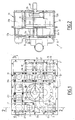
- Figure 1 is a front view from the outside of the storage tank the spreader, the mounting plate of the pump body of the device bitumen transfer from the spreader.
- Figure 2 is a sectional view of the pump body of the device transfer according to 2-2 of figure 1.
- Figure 3 is a sectional view along 3-3 of the pump body of the bitumen transfer device from the spreader.
- Figures 4 to 10 are block diagrams showing the components the spreader and the position of the device control valves bitumen transfer from the spreader, to perform seven different functions, thanks to the bitumen transfer device on the spreader.
- the spreader transfer device designated by item 1 has been shown schematically in Figure 4 with the various components of the spreader.
- FIG. 4 These components, represented very schematically on the Figure 4, include a storage tank 5 whose internal volume containing liquid bitumen is represented by the upper part of FIG. 4, two bitumen spreading booms 6a and 6b, a replenishment tank 7 in liquid bitumen from the storage tank 5 and the transfer device liquid bitumen generally designated by reference 1 consisting by the submerged pump shown in Figures 1 to 3 and a set of valves which can be controlled automatically or manual.
- Figures 1, 2 and 3 show the pump body 2 of the pump of the bitumen transfer device 1 consisting of a one-piece molded part with mounting plate 3.
- the mounting plate 3 of the pump body 2 coming from molding with the pump body has, at its periphery, a plurality of openings 8 allowing the fixing of the mounting plate 3 on a wall of the tank 5 of the spreader, at an opening passing through this wall, via mechanical fastening devices with interposition of a seal seal, so that the pump body is placed inside the tank 5 and tightly fixed against the wall of the storage tank 5.
- FIG 1 there is shown the outer face of the mounting plate 3 directed towards the outside of the bitumen storage tank 5.
- molded walls define a pumping chamber 9 inside which two gears are mounted 10a, 10b of a gear pump shown diagrammatically on Figure 4.
- the gears of the gear pump are rotated via a 10 'transmission, the shaft of which is itself connected to a hydraulic motor for rotating the gears in gear by their teeth, in opposite directions, each of the gears being able to turn in one direction or the other depending on the direction of rotation of the motor transmission hydraulic drive 10 '.
- the pump body 2 is crossed by three openings for the passage of bitumen 11, 12 and 13 which connect the internal volume of the pump body 2 with the internal volume of the bitumen storage tank 5, as shown in particular in FIG. 4 where the openings 11, 12 and 13 have been shown at the interface of the transfer device 1 and of the tank bitumen storage 5.
- the openings 11 and 12 have been represented in a wall of the pump body which is immersed in the liquid bitumen when the pump body is fixed by its mounting plate 3 to a wall of the storage tank 5.
- the opening 13 has been represented in FIG. 3 in a arrangement passing through a wall of the pump body 2.
- the mounting plate 3 is itself crossed by four openings 14, 15, 16 and 17 opening onto the external face of the mounting plate 3 shown in FIG. 1.
- the openings 14, 15, 16 and 17 have also been shown on the Figure 4, along one side of the rectangle showing the bitumen transfer device 1 which corresponds to the mounting plate 3.
- fixing means 14 ', 15', 16 'or 17' flanges ensuring the connection of the opening corresponding to the minus one component of the spreader.
- the connection between the flanges fixed on the mounting plate 3 by the fixing means 14 ', 15', 16 ', 17 'and the components of the spreader can be produced by flexible hoses.
- the openings 15 and 17, respectively, are connected to a first end of the first ramp 6a and from the second ramp 6b, the opening 16 to the replenishment tank 7, and the opening 14 at a second end of the ramps 6a and 6b.
- valves each comprising a valve mounted movable in translation inside of the pump body 2, between an open position and a closing of a passage opening of the pump body 2.
- a first valve 21 associated with the passage opening 11 allows to ensure the opening and closing of this opening 11 via a valve 21 connected to the mobile part of a pneumatic cylinder 21 b fixed on the external face of the mounting plate 3 of the pump body.
- control valves of the transfer device 1 are all made in the same way and have a valve that can be moved in translation by a pneumatic cylinder mounted on the external face of the plate mounting 3, between an open position and a closed position an opening through the wall of the pump body or a conduit connecting an internal part of the pump body with a passage opening through the mounting plate 3.
- All the valves of the control valves move in one direction perpendicular to mounting plate 3, thanks to a pneumatic cylinder attached to the outer surface of the mounting plate.
- the control valve 22 visible in particular in Figure 2 comprises a valve 22a movable by a pneumatic cylinder 22b between a position opening and a closed position of the opening 12. In its closed position, the valve 22a is supported on a seat machined in the opening part of the opening 12.
- the opening 13 can be closed by the valve 24a of a control valve 24, the pneumatic cylinder 24b of which is fixed on the face mounting plate 3.
- molded walls allow to define the pumping chamber 9, the section of which is parallel to the mounting plate 3 is oblong in shape. Openings highlighting communication chamber 9, on one side corresponding to an elongated side of the oblong chamber with a first manifold 19 into which opens the closable opening 12 and, on the opposite side of the chamber 9, with a second manifold 20 having a general L shape, in section by a parallel plane to mounting plate 3 and opening 13.
- a first branch 20a of the L-shaped collector 20 communicating with pumping chamber 9 open three conduits connecting, respectively, the collector 20 to the openings 15, 17 and 16 passing through mounting plate 3.
- Each of the connecting channels of an opening 15, 17 or 16 with the manifold 20 has an inlet portion opposite the passage opening corresponding 15, 17 or 16 constituting a support seat for the valve a corresponding control valve whose displacement between a opening and closing position of the entrance to the communication channel, in a direction perpendicular to the mounting plate 3, is controlled by a corresponding pneumatic cylinder 25b, 27b or 26b visible in the figure 1.
- Each of the openings 15, 17 and 16 is equipped with a connected flange to the fixing means 15 ', 17' or 16 'making it possible to connect, respectively, by pipes the opening 15 to the first ramp 6a of the spreader, opening 17 to the second ramp 6b and opening 16 to the tank replenishment 7.
- the second straight branch 20b of the collector 20 has a part end 20'b into which the opening 11 opens towards the storage tank 5 and which has the opening 14 passing through the mounting plate 3 fitted with fixing means 14 'for an opening connection flange 14 at the second ends of the ramps 6a and 6b opposite the ends connected to the respective openings 15 and 17.
- the collector 20 comprises, at the end of its main part 20a, 20b, upstream of the opening 14 (considering a circulation of bitumen coming from the chamber pump 9), a passage opening 18 which can be closed by the valve 23a of a control valve 23 comprising a pneumatic cylinder actuator 23b fixed on the plate 3.
- the end portion 20'b of the collector 20 is completely separate and isolated from the main part 20a, 20b of the collector 20 into which the opening 13 opens.
- the collectors 19 and 20 constitute the internal space of the body of pump communicating with the pumping chamber 9 on a first side of the pumping chamber constituting the suction or discharge side of the pump and on a second side constituting a discharge side or suction, according to the direction of rotation of the gears 10a and 10b of the pump.
- FIGS. 4 to 10 the positions of opening and of closing of valves 21, 22, 23, 24, 25, 26 and 27 and the direction of rotation of the gears 10a and 10b of the pump, during the operation of the bitumen transfer, to perform seven different functions of the spreader.
- valves of valves 22 and 24 are open and all the other valves valve positions are in closed positions.
- the gears of the pump rotate so as to circulate the bitumen from the collector 19 towards the branch 20b of the collector 20, the bitumen being sucked into the storage tank 5 through the opening 12 and discharged into the storage tank 5 by opening 13.
- Valves 21, 22, 25 and 27 are open, all other valves being closed.
- the direction of rotation of the pump gears ensures pumping bitumen from the collector 19 to the collector 20, as above.
- Bitumen is distributed in the ramps 6a and 6b by the valves 25 and 27 and the openings 15 and 17, then runs along the ramps in the direction from their length to their exit to be recovered, through the opening 14 of ramps exit, in part 20'b of collector 20 communicating with the storage tank 5 through the opening 11, the valve 23 being closed.
- the liquid bitumen is returned to the storage tank 5, via of the opening 11, the valve 21 being open.
- Valves 22, 25, 27 and 23 are open and the other valves closed.
- the gears 10a and 10b of the pump rotate so as to suck the bitumen in the collector 19 and to discharge it into the collector 20.
- the ramps 6a and 6b are supplied with bitumen by their two ends, through openings 15 and 17, on the one hand, and through the opening 14 ramp exit, on the other hand, the opening of the valve 23 allowing supplying the opening 14 with liquid bitumen.
- Valves 22 and 26 are open and the other valves closed.
- the gears 10a and 10b of the pump rotate so as to suck the liquid bitumen in the collector 20 and to discharge it into the collector 19.
- the bitumen is thus sucked into the replenishment tank 7 and discharged into the storage tank 5, through the opening 12.
- the control valves 22 and 26 are open, as before, and the pump gears rotate, so as to suck up the bitumen in the collector 19 and to discharge it into the collector 20.
- the bitumen drawn into the storage tank 5 is discharged into the replenishment tank 7.
- Valves 22 and 25 are open and all other valves closed.
- the gears 10a and 10b of the pump are rotated so to suck the bitumen in the collector 20 and to discharge it into the collector 19.
- valves and the direction of rotation of the pump, for draining of the ramp 6b are represented. valves and the direction of rotation of the pump, for draining of the ramp 6b.
- Valves 22 and 27 are open and all other valves closed. The bitumen is sucked into the collector 20 and discharged into the collector 19.
- bitumen transfer device when combined to an installation such as a bitumen spreading installation, allows to put the bitumen in circulation in a regulated manner in the parts of the installation which have been previously chosen to perform a function among many functions using system components, such as active components or a replenishment container of the installation by liquid binder.
- the shape of the pump body and in particular the shape of the space internal of this pump body communicating with the pumping chamber may be different from the form described.
- the arrangement of the openings of passage on or inside the pump body and on the plate mounting may be different from that which has been described.
- the pumping means of the pump arranged in the body of pump can be different from gears and made under any other form allowing pumping of the liquid used in the installation, in satisfactory flow and pressure conditions, depending on the nature of this liquid.
- the liquid transfer device according to the invention can be used on different installations of liquid bitumen spreaders and by example in binder park installations, to carry out the distribution of various types of binder, the supply or emptying of binder or binder spraying devices.
Landscapes
- Engineering & Computer Science (AREA)
- Architecture (AREA)
- Civil Engineering (AREA)
- Structural Engineering (AREA)
- Road Paving Machines (AREA)
- Coating By Spraying Or Casting (AREA)
- Catching Or Destruction (AREA)
- Reciprocating Pumps (AREA)
Abstract
Description
- le brassage du bitume contenu dans la cuve de stockage, pendant les phases d'attente où l'on ne réalise pas d'épandage, le bitume étant mis en circulation par la pompe entre une première et une seconde ouvertures de la cuve ;
- la circulation de bitume à l'intérieur des rampes, également pendant une phase d'attente avec retour du bitume dans la cuve après circulation dans les rampes ;
- l'épandage du bitume par les rampes ;
- le remplissage de la cuve de stockage à partir de la cuve de réapprovisionnement ;
- la vidange de la cuve de stockage en fin d'utilisation par évacuation du bitume dans la cuve de réapprovisionnement ; et
- la vidange de la première ou de la seconde rampe avec retour du bitume dans la cuve de stockage.
- le moyen de commande pour le déplacement en translation du clapet de chacune des vannes de commande est constitué par un vérin pneumatique dont la partie mobile se déplace en translation perpendiculairement à la plaque de montage.
- le corps de pompe présente un espace interne constitué d'un premier collecteur communiquant avec la chambre de pompage d'un premier côté de la chambre de pompage et d'un second collecteur communiquant avec un second côté de la chambre de pompage, l'aspiration ou le refoulement du liquide étant assuré par les moyens de pompage de la pompe, entre le premier côté et le second côté de la chambre de pompage, le premier collecteur étant en communication par une ouverture avec la cuve de stockage de liquide et le second collecteur étant en communication par une première et une seconde ouvertures avec la cuve de stockage, à travers la paroi du corps de pompe et avec au moins l'un d'un composant utilisant le liquide de la pompe et d'une cuve de réapprovisionnement de la cuve de stockage, par au moins une ouverture de passage, à travers la plaque de montage du corps de pompe.
- Les moyens de pompage disposés dans la chambre de pompage du corps de pompe sont associés à des moyens de transmission qui peuvent être commandés pour assurer le pompage du liant bitumineux liquide du premier collecteur vers le second collecteur ou, au contraire, du second collecteur vers le premier collecteur.
- brassage du bitume liquide dans la cuve de stockage de l'épandeuse,
- circulation de bitume liquide dans l'au moins une rampe,
- épandage de bitume par l'au moins une rampe,
- remplissage de la cuve de stockage à partir de la cuve de réapprovisionnement,
- vidange de la cuve de stockage de bitume dans la cuve de réapprovisionnement,
- vidange de l'au moins une rampe.
Claims (6)
- Dispositif de transfert d'un liquide mis en oeuvre dans une installation, entre une cuve de stockage (5) du liquide et au moins l'un d'un composant (6a, 6b) utilisant le liquide et d'une cuve de réapprovisionnement (7) de la cuve de stockage (5), comportant une pompe ayant un corps de pompe (2) solidaire d'une plaque de montage (3) fixée sur une paroi de la cuve de stockage (5), de manière que le corps de pompe (2) soit immergé dans la cuve de stockage (5), une chambre de pompage (9) renfermant des moyens de pompage (10a, 10b), contenue dans le corps de pompe (2), des ouvertures de passage (11, 12, 13, 14, 15, 16, 17, 18) du corps de pompe (2) et des vannes de commande (21, 22, 23, 24, 25, 26, 27) pour l'ouverture et la fermeture des ouvertures du corps de pompe (2) pour autoriser ou empêcher le passage de liquide à travers les ouvertures de passage du corps de pompe (2), pour assurer le transfert du liquide entre la cuve de stockage (5) et l'un au moins du composant (6a, 6b) et de la cuve de réapprovisionnement (7), caractérisé par le fait que les vannes de commande (21, 22, 23, 24, 25, 26, 27) comportent chacune un clapet (21a, 22a, 23a, 24a, 25a, 26a, 27a) monté mobile dans le corps de pompe (2) et commandé pour son déplacement en translation entre au moins une position d'ouverture et au moins une position de fermeture d'une ouverture de passage du corps de pompe, par un moyen de commande (21 b, 22b, 23b, 24b, 25b, 26b, 27b) fixé sur la plaque de montage (3), à l'extérieur de la cuve de stockage (5).
- Dispositif suivant la revendication 1, caractérisé par le fait que le moyen de commande pour le déplacement en translation du clapet de chacune des vannes de commande (21, 22, 23, 24, 25, 26, 27) est constitué par un vérin pneumatique dont la partie mobile se déplace en translation perpendiculairement à la plaque de montage (3).
- Dispositif suivant l'une quelconque des revendications 1 et 2, caractérisé par le fait que le corps de pompe (2) présente un espace interne constitué d'un premier collecteur (19) communiquant avec la chambre de pompage (9) d'un premier côté de la chambre de pompage et d'un second collecteur (20) communiquant avec un second côté de la chambre de pompage (9), l'aspiration ou le refoulement du liquide étant assuré par les moyens de pompage (10a, 10b) de la pompe, entre le premier côté et le second côté de la chambre de pompage (9), le premier collecteur (19) étant en communication par une ouverture (12) avec la cuve de stockage de liquide (5) et le second collecteur (20) étant en communication par une première et une seconde ouvertures (13, 11) avec la cuve de stockage (5), à travers la paroi du corps de pompe (2) et avec au moins l'un d'un composant utilisant le liquide de la pompe et d'une cuve de réapprovisionnement (7) de la cuve de stockage (5), par au moins une ouverture de passage (14, 15, 17, 16), à travers la plaque de montage (3) du corps de pompe (2).
- Epandeuse de liant bitumineux comportant une cuve de stockage (5) de liant bitumineux, et au moins une rampe d'épandage (6a, 6b) et associée à une cuve de réapprovisionnement (7) de la cuve de stockage de bitume (5) de l'épandeuse, caractérisée par le fait qu'elle comporte un dispositif (1) de transfert de liant bitumineux suivant la revendication 3, dont le premier collecteur (19) communique avec la cuve de stockage (5) par une ouverture (12) obturable par un clapet (22a) d'une vanne de commande (22) et dont le second collecteur (20) comporte, dans une partie principale (20a, 20b), la première ouverture (13) communiquant avec la cuve de stockage (5), à travers la paroi du corps de pompe (2) immergé dans la cuve (5), au moins un moyen de mise en communication du second collecteur (20) avec au moins une ouverture (15, 17) traversant la plaque de montage (3) pour assurer la liaison du second collecteur (20) à l'au moins une rampe d'épandage (6a, 6b) du liant bitumineux et un moyen de mise en communication du second collecteur (20) avec une ouverture (6) traversant la plaque de montage (3) pour la mise en communication du second collecteur (20) avec une cuve de réapprovisionnement (7) de la cuve de stockage de bitume (5) de l'épandeuse, la première ouverture (13) du second collecteur (20) débouchant dans la cuve de stockage (5) et les moyens de mise en communication du second collecteur (20) avec les ouvertures (15, 17, 16) traversant la plaque de montage (3) étant obturables par des clapets de vannes de commande respectives (21, 24, 25, 27, 26), le second collecteur (20) étant de plus en communication avec la cuve de stockage (5) par la seconde ouverture (11) à travers la paroi du corps de pompe (2) obturable par un clapet de vanne (21b) et avec l'au moins une rampe d'épandage (6a, 6b) par une ouverture (14) traversant la plaque de montage (3) dans une partie d'extrémité (20'b) du second collecteur (20) communiquant avec la cuve de stockage (5) par la seconde ouverture (11), la partie d'extrémité (20'b) du second collecteur (20) étant en communication avec la partie principale (20a, 20b) du second collecteur (20) par une ouverture (18) obturable par un clapet de fermeture (23b) d'une vanne de commande (23).
- Epandeuse suivant la revendication 4, caractérisée par le fait que les moyens de pompage (10a, 10b) disposés dans la chambre de pompage (9) du corps de pompe (2) sont associés à des moyens de transmission (10') qui peuvent être commandés pour assurer le pompage du liant bitumineux liquide du premier collecteur (19) vers le second collecteur (20) ou, au contraire, du second collecteur (20) vers le premier collecteur (19).
- Procédé d'exploitation par transfert de liant bitumineux liquide d'une épandeuse selon la revendication 5, caractérisé par le fait que, par ouverture et fermeture de vannes (21, 22, 23, 24, 25, 26, 27) de commande du dispositif de transfert (1), on réalise au moins l'une quelconque des fonctions suivantes de l'épandeuse :brassage du bitume liquide dans la cuve de stockage (5) de l'épandeuse,circulation de bitume liquide dans l'au moins une rampe (6a, 6b),épandage de bitume par l'au moins une rampe (6a, 6b),remplissage de la cuve de stockage (5) à partir de la cuve de réapprovisionnement (7),vidange de la cuve de stockage de bitume (5) dans la cuve de réapprovisionnement (7),vidange de l'au moins une rampe (6a, 6b).
Applications Claiming Priority (2)
| Application Number | Priority Date | Filing Date | Title |
|---|---|---|---|
| FR0214824 | 2002-11-26 | ||
| FR0214824A FR2847566B1 (fr) | 2002-11-26 | 2002-11-26 | Dispositif de transfert d'un liquide dans une installation, epandeuse de liant bitumineux comportant un dispositif de transfert de liant et procede d'exploitation de l'epandeuse |
Publications (2)
| Publication Number | Publication Date |
|---|---|
| EP1424446A1 true EP1424446A1 (fr) | 2004-06-02 |
| EP1424446B1 EP1424446B1 (fr) | 2008-03-26 |
Family
ID=32241628
Family Applications (1)
| Application Number | Title | Priority Date | Filing Date |
|---|---|---|---|
| EP03292886A Expired - Lifetime EP1424446B1 (fr) | 2002-11-26 | 2003-11-20 | Dispositif de transfert d'un liquide dans une installation, épandeuse de liant bitumineux comportant un dispositif de transfert de liant et procédé d'exploitation de l'épandeuse |
Country Status (5)
| Country | Link |
|---|---|
| EP (1) | EP1424446B1 (fr) |
| CN (1) | CN1532339A (fr) |
| AT (1) | ATE390517T1 (fr) |
| DE (1) | DE60319937D1 (fr) |
| FR (1) | FR2847566B1 (fr) |
Cited By (1)
| Publication number | Priority date | Publication date | Assignee | Title |
|---|---|---|---|---|
| CN105821742A (zh) * | 2016-04-20 | 2016-08-03 | 浙江美通筑路机械股份有限公司 | 一种用于沥青或防水涂料的洒布装置 |
Families Citing this family (1)
| Publication number | Priority date | Publication date | Assignee | Title |
|---|---|---|---|---|
| US10385521B1 (en) * | 2018-05-10 | 2019-08-20 | Caterpillar Sarl | Paving machine with an emulsion tank |
Citations (2)
| Publication number | Priority date | Publication date | Assignee | Title |
|---|---|---|---|---|
| US3361358A (en) * | 1966-01-28 | 1968-01-02 | Solem Machine Company | Apparatus for spreading bituminous material |
| FR2822856A1 (fr) * | 2001-03-29 | 2002-10-04 | Secmair | Dispositif de distribution selective d'un liant et vehicule comportant un tel dispositif |
-
2002
- 2002-11-26 FR FR0214824A patent/FR2847566B1/fr not_active Expired - Fee Related
-
2003
- 2003-11-20 AT AT03292886T patent/ATE390517T1/de not_active IP Right Cessation
- 2003-11-20 DE DE60319937T patent/DE60319937D1/de not_active Expired - Lifetime
- 2003-11-20 EP EP03292886A patent/EP1424446B1/fr not_active Expired - Lifetime
- 2003-11-25 CN CNA2003101097966A patent/CN1532339A/zh active Pending
Patent Citations (2)
| Publication number | Priority date | Publication date | Assignee | Title |
|---|---|---|---|---|
| US3361358A (en) * | 1966-01-28 | 1968-01-02 | Solem Machine Company | Apparatus for spreading bituminous material |
| FR2822856A1 (fr) * | 2001-03-29 | 2002-10-04 | Secmair | Dispositif de distribution selective d'un liant et vehicule comportant un tel dispositif |
Cited By (1)
| Publication number | Priority date | Publication date | Assignee | Title |
|---|---|---|---|---|
| CN105821742A (zh) * | 2016-04-20 | 2016-08-03 | 浙江美通筑路机械股份有限公司 | 一种用于沥青或防水涂料的洒布装置 |
Also Published As
| Publication number | Publication date |
|---|---|
| FR2847566B1 (fr) | 2005-02-25 |
| EP1424446B1 (fr) | 2008-03-26 |
| CN1532339A (zh) | 2004-09-29 |
| DE60319937D1 (de) | 2008-05-08 |
| FR2847566A1 (fr) | 2004-05-28 |
| ATE390517T1 (de) | 2008-04-15 |
Similar Documents
| Publication | Publication Date | Title |
|---|---|---|
| EP1173383B1 (fr) | Machine de remplissage comportant des moyens perfectionnes de nettoyage | |
| EP1424446B1 (fr) | Dispositif de transfert d'un liquide dans une installation, épandeuse de liant bitumineux comportant un dispositif de transfert de liant et procédé d'exploitation de l'épandeuse | |
| FR2757088A1 (fr) | Procede et unite de nettoyage de cuves | |
| FR3092567A1 (fr) | Bec de remplissage a depression | |
| EP3274260B1 (fr) | Dispositif de dosage volumetrique pour machine de remplissage de recipients | |
| FR2497321A1 (fr) | Raccord tournant a fluide permettant le passage de pistons-racleurs | |
| EP0310488A1 (fr) | Regard pour installations de transport de fluide | |
| EP1186802A1 (fr) | Dispositif d'entraínement comprenant un moteur hydraulique et un réducteur | |
| EP0961894B1 (fr) | Valve monostable | |
| EP3228869B1 (fr) | Pompe submersible et procédé de mise en fonctionnement d'une telle pompe | |
| FR2974551A1 (fr) | Systeme compact de stockage et d'evacuation des eaux noires d'un vehicule muni de toilettes a cassettes. | |
| EP3786375B1 (fr) | Robinet pour réservoir de chasse d eau | |
| CA3049218A1 (fr) | Systeme et necessaire de purge d'un reservoir et procedes de purge et de montage associes | |
| CA3049216A1 (fr) | Ensemble de production d'energie et procede de purge de l'eau contenue dans un reservoir d'aeronef associe | |
| EP0457682B1 (fr) | Procédé de débouchage d'une tuyauterie véhiculant des produits dangereux | |
| FR2678181A1 (fr) | Rampe de pulverisation. | |
| EP0771897B1 (fr) | Machine de traitement, notamment textile, comprenant une cuve amovible et une borne technique fixe | |
| WO2017207951A1 (fr) | Pompe de circulation trois voies a obstruction commandee | |
| FR2813755A1 (fr) | Procede de commande de la configuration en mode "incorporation" d'un circuit d'eau d'un pulverisateur agricole et pulverisateur agricole utilisant un tel procede | |
| FR2605253A1 (fr) | Installation d'enfutage | |
| EP1875017B1 (fr) | Robot de nettoyage automatique du fond d'une piscine | |
| WO2005100188A2 (fr) | Dispositif de distribution de produits a obturateur rotatif | |
| FR2639405A1 (fr) | Dispositif de prelevement de liquide dans une capacite et en particulier dispositif de puisage de carburant dans le reservoir d'un vehicule automobile | |
| FR2512162A1 (fr) | Structure de soupape de vidange pour des recipients du type citerne, notamment pour des wagons-citernes | |
| EP3393965B1 (fr) | Equipement comprenant une vanne coaxiale insérable pour transférer un fluide dans un réservoir et procédé |
Legal Events
| Date | Code | Title | Description |
|---|---|---|---|
| PUAI | Public reference made under article 153(3) epc to a published international application that has entered the european phase |
Free format text: ORIGINAL CODE: 0009012 |
|
| AK | Designated contracting states |
Kind code of ref document: A1 Designated state(s): AT BE BG CH CY CZ DE DK EE ES FI FR GB GR HU IE IT LI LU MC NL PT RO SE SI SK TR |
|
| AX | Request for extension of the european patent |
Extension state: AL LT LV MK |
|
| 17P | Request for examination filed |
Effective date: 20041125 |
|
| AKX | Designation fees paid |
Designated state(s): AT BE BG CH CY CZ DE DK EE ES FI FR GB GR HU IE IT LI LU MC NL PT RO SE SI SK TR |
|
| GRAP | Despatch of communication of intention to grant a patent |
Free format text: ORIGINAL CODE: EPIDOSNIGR1 |
|
| GRAS | Grant fee paid |
Free format text: ORIGINAL CODE: EPIDOSNIGR3 |
|
| GRAA | (expected) grant |
Free format text: ORIGINAL CODE: 0009210 |
|
| AK | Designated contracting states |
Kind code of ref document: B1 Designated state(s): AT BE BG CH CY CZ DE DK EE ES FI FR GB GR HU IE IT LI LU MC NL PT RO SE SI SK TR |
|
| REG | Reference to a national code |
Ref country code: GB Ref legal event code: FG4D Free format text: NOT ENGLISH |
|
| REG | Reference to a national code |
Ref country code: CH Ref legal event code: EP Ref country code: IE Ref legal event code: FG4D Free format text: LANGUAGE OF EP DOCUMENT: FRENCH |
|
| REF | Corresponds to: |
Ref document number: 60319937 Country of ref document: DE Date of ref document: 20080508 Kind code of ref document: P |
|
| PG25 | Lapsed in a contracting state [announced via postgrant information from national office to epo] |
Ref country code: FI Free format text: LAPSE BECAUSE OF FAILURE TO SUBMIT A TRANSLATION OF THE DESCRIPTION OR TO PAY THE FEE WITHIN THE PRESCRIBED TIME-LIMIT Effective date: 20080326 |
|
| PG25 | Lapsed in a contracting state [announced via postgrant information from national office to epo] |
Ref country code: AT Free format text: LAPSE BECAUSE OF FAILURE TO SUBMIT A TRANSLATION OF THE DESCRIPTION OR TO PAY THE FEE WITHIN THE PRESCRIBED TIME-LIMIT Effective date: 20080326 |
|
| NLV1 | Nl: lapsed or annulled due to failure to fulfill the requirements of art. 29p and 29m of the patents act | ||
| PG25 | Lapsed in a contracting state [announced via postgrant information from national office to epo] |
Ref country code: SI Free format text: LAPSE BECAUSE OF FAILURE TO SUBMIT A TRANSLATION OF THE DESCRIPTION OR TO PAY THE FEE WITHIN THE PRESCRIBED TIME-LIMIT Effective date: 20080326 |
|
| REG | Reference to a national code |
Ref country code: IE Ref legal event code: FD4D |
|
| PG25 | Lapsed in a contracting state [announced via postgrant information from national office to epo] |
Ref country code: SE Free format text: LAPSE BECAUSE OF FAILURE TO SUBMIT A TRANSLATION OF THE DESCRIPTION OR TO PAY THE FEE WITHIN THE PRESCRIBED TIME-LIMIT Effective date: 20080626 Ref country code: PT Free format text: LAPSE BECAUSE OF FAILURE TO SUBMIT A TRANSLATION OF THE DESCRIPTION OR TO PAY THE FEE WITHIN THE PRESCRIBED TIME-LIMIT Effective date: 20080901 Ref country code: ES Free format text: LAPSE BECAUSE OF FAILURE TO SUBMIT A TRANSLATION OF THE DESCRIPTION OR TO PAY THE FEE WITHIN THE PRESCRIBED TIME-LIMIT Effective date: 20080707 Ref country code: SK Free format text: LAPSE BECAUSE OF FAILURE TO SUBMIT A TRANSLATION OF THE DESCRIPTION OR TO PAY THE FEE WITHIN THE PRESCRIBED TIME-LIMIT Effective date: 20080326 Ref country code: CZ Free format text: LAPSE BECAUSE OF FAILURE TO SUBMIT A TRANSLATION OF THE DESCRIPTION OR TO PAY THE FEE WITHIN THE PRESCRIBED TIME-LIMIT Effective date: 20080326 |
|
| PG25 | Lapsed in a contracting state [announced via postgrant information from national office to epo] |
Ref country code: NL Free format text: LAPSE BECAUSE OF FAILURE TO SUBMIT A TRANSLATION OF THE DESCRIPTION OR TO PAY THE FEE WITHIN THE PRESCRIBED TIME-LIMIT Effective date: 20080326 Ref country code: RO Free format text: LAPSE BECAUSE OF FAILURE TO SUBMIT A TRANSLATION OF THE DESCRIPTION OR TO PAY THE FEE WITHIN THE PRESCRIBED TIME-LIMIT Effective date: 20080326 |
|
| PG25 | Lapsed in a contracting state [announced via postgrant information from national office to epo] |
Ref country code: DE Free format text: LAPSE BECAUSE OF FAILURE TO SUBMIT A TRANSLATION OF THE DESCRIPTION OR TO PAY THE FEE WITHIN THE PRESCRIBED TIME-LIMIT Effective date: 20080627 Ref country code: DK Free format text: LAPSE BECAUSE OF FAILURE TO SUBMIT A TRANSLATION OF THE DESCRIPTION OR TO PAY THE FEE WITHIN THE PRESCRIBED TIME-LIMIT Effective date: 20080326 Ref country code: IE Free format text: LAPSE BECAUSE OF FAILURE TO SUBMIT A TRANSLATION OF THE DESCRIPTION OR TO PAY THE FEE WITHIN THE PRESCRIBED TIME-LIMIT Effective date: 20080326 |
|
| PLBE | No opposition filed within time limit |
Free format text: ORIGINAL CODE: 0009261 |
|
| STAA | Information on the status of an ep patent application or granted ep patent |
Free format text: STATUS: NO OPPOSITION FILED WITHIN TIME LIMIT |
|
| 26N | No opposition filed |
Effective date: 20081230 |
|
| PG25 | Lapsed in a contracting state [announced via postgrant information from national office to epo] |
Ref country code: EE Free format text: LAPSE BECAUSE OF FAILURE TO SUBMIT A TRANSLATION OF THE DESCRIPTION OR TO PAY THE FEE WITHIN THE PRESCRIBED TIME-LIMIT Effective date: 20080326 Ref country code: BG Free format text: LAPSE BECAUSE OF FAILURE TO SUBMIT A TRANSLATION OF THE DESCRIPTION OR TO PAY THE FEE WITHIN THE PRESCRIBED TIME-LIMIT Effective date: 20080626 |
|
| BERE | Be: lapsed |
Owner name: FAMARO Effective date: 20081130 |
|
| PG25 | Lapsed in a contracting state [announced via postgrant information from national office to epo] |
Ref country code: MC Free format text: LAPSE BECAUSE OF NON-PAYMENT OF DUE FEES Effective date: 20081130 |
|
| REG | Reference to a national code |
Ref country code: CH Ref legal event code: PL |
|
| GBPC | Gb: european patent ceased through non-payment of renewal fee |
Effective date: 20081120 |
|
| PG25 | Lapsed in a contracting state [announced via postgrant information from national office to epo] |
Ref country code: IT Free format text: LAPSE BECAUSE OF FAILURE TO SUBMIT A TRANSLATION OF THE DESCRIPTION OR TO PAY THE FEE WITHIN THE PRESCRIBED TIME-LIMIT Effective date: 20080326 |
|
| REG | Reference to a national code |
Ref country code: FR Ref legal event code: ST Effective date: 20090731 |
|
| PG25 | Lapsed in a contracting state [announced via postgrant information from national office to epo] |
Ref country code: CY Free format text: LAPSE BECAUSE OF FAILURE TO SUBMIT A TRANSLATION OF THE DESCRIPTION OR TO PAY THE FEE WITHIN THE PRESCRIBED TIME-LIMIT Effective date: 20080326 Ref country code: BE Free format text: LAPSE BECAUSE OF NON-PAYMENT OF DUE FEES Effective date: 20081130 |
|
| PG25 | Lapsed in a contracting state [announced via postgrant information from national office to epo] |
Ref country code: CH Free format text: LAPSE BECAUSE OF NON-PAYMENT OF DUE FEES Effective date: 20081130 Ref country code: LI Free format text: LAPSE BECAUSE OF NON-PAYMENT OF DUE FEES Effective date: 20081130 |
|
| PG25 | Lapsed in a contracting state [announced via postgrant information from national office to epo] |
Ref country code: GB Free format text: LAPSE BECAUSE OF NON-PAYMENT OF DUE FEES Effective date: 20081120 |
|
| PG25 | Lapsed in a contracting state [announced via postgrant information from national office to epo] |
Ref country code: HU Free format text: LAPSE BECAUSE OF FAILURE TO SUBMIT A TRANSLATION OF THE DESCRIPTION OR TO PAY THE FEE WITHIN THE PRESCRIBED TIME-LIMIT Effective date: 20080927 Ref country code: LU Free format text: LAPSE BECAUSE OF NON-PAYMENT OF DUE FEES Effective date: 20081120 |
|
| PG25 | Lapsed in a contracting state [announced via postgrant information from national office to epo] |
Ref country code: TR Free format text: LAPSE BECAUSE OF FAILURE TO SUBMIT A TRANSLATION OF THE DESCRIPTION OR TO PAY THE FEE WITHIN THE PRESCRIBED TIME-LIMIT Effective date: 20080326 |
|
| PG25 | Lapsed in a contracting state [announced via postgrant information from national office to epo] |
Ref country code: GR Free format text: LAPSE BECAUSE OF FAILURE TO SUBMIT A TRANSLATION OF THE DESCRIPTION OR TO PAY THE FEE WITHIN THE PRESCRIBED TIME-LIMIT Effective date: 20080627 |
|
| PG25 | Lapsed in a contracting state [announced via postgrant information from national office to epo] |
Ref country code: FR Free format text: LAPSE BECAUSE OF NON-PAYMENT OF DUE FEES Effective date: 20081130 |