EP1424139A1 - Method for the surface treatment of a flat-structured material - Google Patents
Method for the surface treatment of a flat-structured material Download PDFInfo
- Publication number
- EP1424139A1 EP1424139A1 EP03026783A EP03026783A EP1424139A1 EP 1424139 A1 EP1424139 A1 EP 1424139A1 EP 03026783 A EP03026783 A EP 03026783A EP 03026783 A EP03026783 A EP 03026783A EP 1424139 A1 EP1424139 A1 EP 1424139A1
- Authority
- EP
- European Patent Office
- Prior art keywords
- treatment
- flat
- structured material
- cylinder
- surface sides
- Prior art date
- Legal status (The legal status is an assumption and is not a legal conclusion. Google has not performed a legal analysis and makes no representation as to the accuracy of the status listed.)
- Granted
Links
- 239000000463 material Substances 0.000 title claims abstract description 84
- 238000000034 method Methods 0.000 title claims abstract description 53
- 238000004381 surface treatment Methods 0.000 title claims description 8
- 239000007788 liquid Substances 0.000 claims abstract description 29
- 239000007787 solid Substances 0.000 claims abstract description 23
- 239000000203 mixture Substances 0.000 claims abstract description 12
- 230000001105 regulatory effect Effects 0.000 claims abstract description 8
- 239000004744 fabric Substances 0.000 claims description 29
- 239000000126 substance Substances 0.000 claims description 15
- 230000000694 effects Effects 0.000 claims description 14
- 229920002994 synthetic fiber Polymers 0.000 claims description 11
- 238000004043 dyeing Methods 0.000 claims description 8
- 239000002904 solvent Substances 0.000 claims description 8
- XLYOFNOQVPJJNP-UHFFFAOYSA-N water Substances O XLYOFNOQVPJJNP-UHFFFAOYSA-N 0.000 claims description 8
- 239000004753 textile Substances 0.000 claims description 7
- 241001465754 Metazoa Species 0.000 claims description 6
- 235000013311 vegetables Nutrition 0.000 claims description 6
- 229910000831 Steel Inorganic materials 0.000 claims description 4
- 239000010985 leather Substances 0.000 claims description 4
- 229920000728 polyester Polymers 0.000 claims description 4
- -1 polypropylene Polymers 0.000 claims description 4
- 239000010959 steel Substances 0.000 claims description 4
- 239000004677 Nylon Substances 0.000 claims description 3
- 229920001778 nylon Polymers 0.000 claims description 3
- 235000007173 Abies balsamea Nutrition 0.000 claims description 2
- 229920002972 Acrylic fiber Polymers 0.000 claims description 2
- 244000025254 Cannabis sativa Species 0.000 claims description 2
- 235000012766 Cannabis sativa ssp. sativa var. sativa Nutrition 0.000 claims description 2
- 235000012765 Cannabis sativa ssp. sativa var. spontanea Nutrition 0.000 claims description 2
- 240000000491 Corchorus aestuans Species 0.000 claims description 2
- 235000011777 Corchorus aestuans Nutrition 0.000 claims description 2
- 235000010862 Corchorus capsularis Nutrition 0.000 claims description 2
- 229920000742 Cotton Polymers 0.000 claims description 2
- 244000018716 Impatiens biflora Species 0.000 claims description 2
- 239000004698 Polyethylene Substances 0.000 claims description 2
- 239000004743 Polypropylene Substances 0.000 claims description 2
- 229920000297 Rayon Polymers 0.000 claims description 2
- 241001416177 Vicugna pacos Species 0.000 claims description 2
- 241000282840 Vicugna vicugna Species 0.000 claims description 2
- 235000009120 camo Nutrition 0.000 claims description 2
- 235000005607 chanvre indien Nutrition 0.000 claims description 2
- 239000002537 cosmetic Substances 0.000 claims description 2
- 239000006071 cream Substances 0.000 claims description 2
- 239000003599 detergent Substances 0.000 claims description 2
- 239000011487 hemp Substances 0.000 claims description 2
- 239000008267 milk Substances 0.000 claims description 2
- 235000013336 milk Nutrition 0.000 claims description 2
- 210000004080 milk Anatomy 0.000 claims description 2
- 210000000050 mohair Anatomy 0.000 claims description 2
- 239000004745 nonwoven fabric Substances 0.000 claims description 2
- 239000002304 perfume Substances 0.000 claims description 2
- 239000004033 plastic Substances 0.000 claims description 2
- 229920003023 plastic Polymers 0.000 claims description 2
- 229920000573 polyethylene Polymers 0.000 claims description 2
- 229920000139 polyethylene terephthalate Polymers 0.000 claims description 2
- 239000005020 polyethylene terephthalate Substances 0.000 claims description 2
- 229920001155 polypropylene Polymers 0.000 claims description 2
- 229920000915 polyvinyl chloride Polymers 0.000 claims description 2
- 239000004800 polyvinyl chloride Substances 0.000 claims description 2
- 239000011148 porous material Substances 0.000 claims description 2
- 238000003825 pressing Methods 0.000 claims description 2
- 238000001035 drying Methods 0.000 claims 1
- 239000000047 product Substances 0.000 claims 1
- 238000005498 polishing Methods 0.000 description 4
- 210000001520 comb Anatomy 0.000 description 2
- 238000010438 heat treatment Methods 0.000 description 2
- 238000007654 immersion Methods 0.000 description 2
- 238000010981 drying operation Methods 0.000 description 1
- 238000005470 impregnation Methods 0.000 description 1
- 230000035515 penetration Effects 0.000 description 1
- 239000000725 suspension Substances 0.000 description 1
- 239000002699 waste material Substances 0.000 description 1
Images


Classifications
-
- B—PERFORMING OPERATIONS; TRANSPORTING
- B05—SPRAYING OR ATOMISING IN GENERAL; APPLYING FLUENT MATERIALS TO SURFACES, IN GENERAL
- B05C—APPARATUS FOR APPLYING FLUENT MATERIALS TO SURFACES, IN GENERAL
- B05C1/00—Apparatus in which liquid or other fluent material is applied to the surface of the work by contact with a member carrying the liquid or other fluent material, e.g. a porous member loaded with a liquid to be applied as a coating
- B05C1/04—Apparatus in which liquid or other fluent material is applied to the surface of the work by contact with a member carrying the liquid or other fluent material, e.g. a porous member loaded with a liquid to be applied as a coating for applying liquid or other fluent material to work of indefinite length
- B05C1/08—Apparatus in which liquid or other fluent material is applied to the surface of the work by contact with a member carrying the liquid or other fluent material, e.g. a porous member loaded with a liquid to be applied as a coating for applying liquid or other fluent material to work of indefinite length using a roller or other rotating member which contacts the work along a generating line
- B05C1/0826—Apparatus in which liquid or other fluent material is applied to the surface of the work by contact with a member carrying the liquid or other fluent material, e.g. a porous member loaded with a liquid to be applied as a coating for applying liquid or other fluent material to work of indefinite length using a roller or other rotating member which contacts the work along a generating line the work being a web or sheets
- B05C1/0834—Apparatus in which liquid or other fluent material is applied to the surface of the work by contact with a member carrying the liquid or other fluent material, e.g. a porous member loaded with a liquid to be applied as a coating for applying liquid or other fluent material to work of indefinite length using a roller or other rotating member which contacts the work along a generating line the work being a web or sheets the coating roller co-operating with other rollers, e.g. dosing, transfer rollers
-
- D—TEXTILES; PAPER
- D06—TREATMENT OF TEXTILES OR THE LIKE; LAUNDERING; FLEXIBLE MATERIALS NOT OTHERWISE PROVIDED FOR
- D06B—TREATING TEXTILE MATERIALS USING LIQUIDS, GASES OR VAPOURS
- D06B1/00—Applying liquids, gases or vapours onto textile materials to effect treatment, e.g. washing, dyeing, bleaching, sizing or impregnating
- D06B1/10—Applying liquids, gases or vapours onto textile materials to effect treatment, e.g. washing, dyeing, bleaching, sizing or impregnating by contact with a member carrying the treating material
-
- D—TEXTILES; PAPER
- D06—TREATMENT OF TEXTILES OR THE LIKE; LAUNDERING; FLEXIBLE MATERIALS NOT OTHERWISE PROVIDED FOR
- D06M—TREATMENT, NOT PROVIDED FOR ELSEWHERE IN CLASS D06, OF FIBRES, THREADS, YARNS, FABRICS, FEATHERS OR FIBROUS GOODS MADE FROM SUCH MATERIALS
- D06M23/00—Treatment of fibres, threads, yarns, fabrics or fibrous goods made from such materials, characterised by the process
- D06M23/16—Processes for the non-uniform application of treating agents, e.g. one-sided treatment; Differential treatment
Definitions
- the present invention relates to a method for the treatment of one of the sides of a flat-structured material having a large surface development and highly reduced thickness with respect to this surface development, from a minimum working height (weft) to a maximum of 2.50 m (2,500 mm) which, when necessary, can be wrapped into a cylindrical roll, both at the inlet (before treatment) and at the outlet (after treatment).
- the method substantially comprises the contact of the surface of interest with a moving solid, which, in turn, is in contact with another solid, the latter also in movement and partially immersed in a liquid bath in which it is soaked and of which it soaks the surface of the previous solid.
- the composition and temperature of the liquid bath are suitably selected in relation to the result to be obtained on the surface of the material to be treated.
- the method also envisages that the material thus treated be finally sent for suitable finishing treatment: in particular, the material treated is sent to a heated cylinder having on its circumference from two to infinite traces with rounded steel bars and/or a completely smooth cylinder. The material slides to the cylinder by means of a closed-ring felt, where it is dried and pressed between the two bodies (heated cylinder and felt).
- the present invention also relates to the devices used for the embodiment of the method defined above. More specifically, the object of the present invention relates to a method for preparing fabrics having different "feel effects" and/or coloured “visible effects", obtained by treating the same on one side only.
- a brush is situated above this cylinder, which, by pressing against the cylinder, collects the liquid from said cylinder and transfers it to the pile side of the fabric, i.e. onto the "loden"-type straight side.
- the fabric thus treated is normally sent onto a heated cylinder, equipped with knurled combs, which completes the polishing operation of the pile and effects the alignment of the pile.
- fabrics with particular "feel effects" can be prepared by applying specific chemical products to the same, according to procedures which envisage the complete immersion of the fabric in the solution (or suspension) of the chemical product of interest, (foulard) and the subsequent drying operation of the fabric thus impregnated; this kind of procedure inevitably leads to the excessive waste of chemical products and, furthermore, it is also impossible to obtain a fabric with two sides treated in different ways.
- immersion procedures can also be avoided by effecting surface treatment of the fabrics by means of printing or laying operations on one side only, allowing fabrics to be obtained with patterns on a white or on a coloured background.
- the object of the present invention relates, in fact, to a method for the treatment of one of the surface sides of a flat-structured material with a large surface development and highly reduced thickness with respect to this surface development, capable, if necessary, of being wrapped in the form of a cylindrical roll both at the inlet (before treatment) and outlet (after treatment).
- the method according to the present invention comprises:
- the moving solid is preferably a collecting brush of the liquid made of animal, vegetable or synthetic fibre (nylon, etc.).
- the brush can be made up of aligned fibres with a uniform height or aligned fibres alternating with empty spaces.
- the brush can consist of a pattern-shaped cylinder made of various materials (figure 3) of which the rate of the patterned cylinder is the same as the rate of the fabric being treated.
- Figure 3 shows an illustrative detail of this solid.
- materials which can, in fact, be subjected to the above surface treatment are: natural and synthetic, or artificial fabrics; non-woven fabrics, and, according to a more general definition, materials from any type of natural fibres such as vegetable or animal fibres; all kinds of synthetic and artificial fibres; vegetable fibres such as linen, cotton, ramiè, hemp, jute fabrics, furs and others; all kinds of paper; animal fibres such as silk, woollen fabrics such as, for example, cachemire, alpaca, vicuna, mohair and furs; or hide, furs and leather in general; synthetic fibres such as polyester fabrics, polyester furs and acrylic fibres; artificial fibres such as fabrics made of viscose, nylon and others, or plastic materials such as polypropylene, polyethylene, PVC, PET, furs and the like.
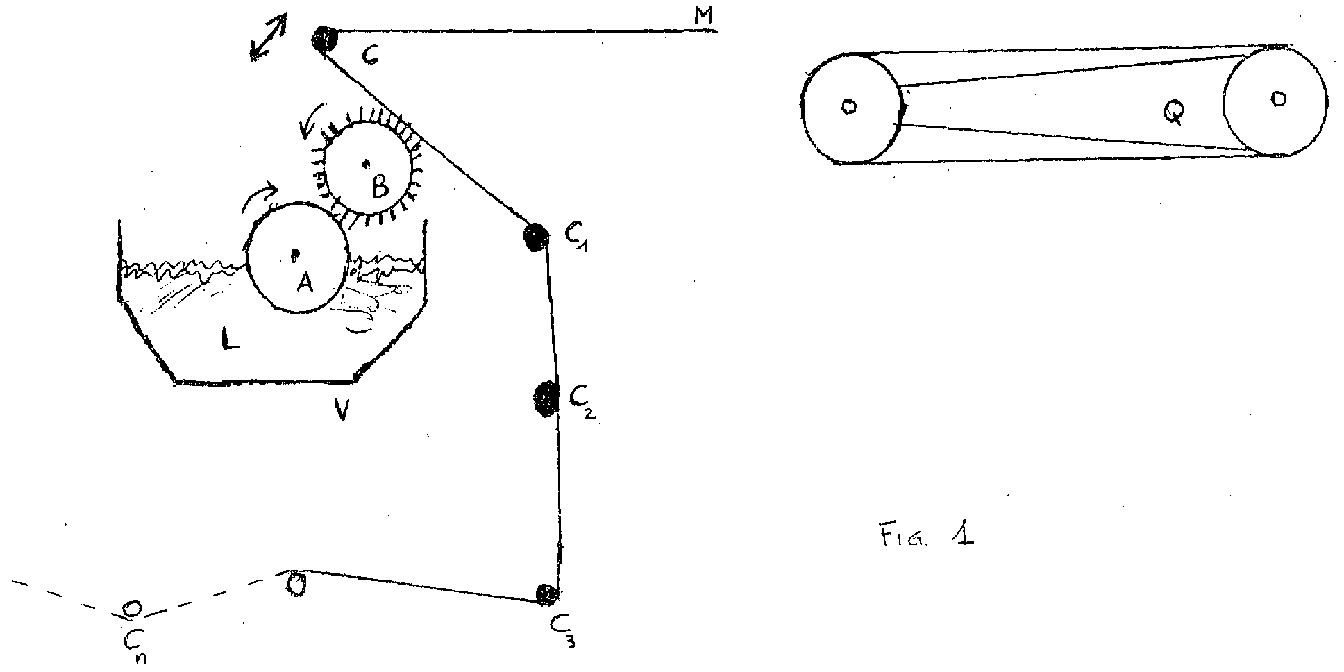
- the method for the treatment of one of the sides of a flat-structured material with a large surface development and highly reduced thickness with respect to said surface development from a minimum working height (weft) to a maximum of 2.50 m (2,500 mm) envisages that the material to be treated (M in figure 1) enter into contact (a) on the part of the surface of interest with a cylindrical brush, on which it presses due to the mechanical movement of a cylinder (C in figure 1), creating a lesser or greater distance between the fabric and the brush (b).
- the rotating brush (b) comes into contact with a cylindrical body which undergoes a rotating movement, regulated (c) in the opposite direction to that of the cylindrical brush.
- This second cylinder is partially immersed in a liquid bath, whose temperature and composition are programmed (d) in relation to the effect to be obtained on the material with the treatment itself; once the material has undergone controlled impregnation, it is passed (e) over a heated cylinder having on its circumference from two to infinite traces with rounded steel bars and/or a completely smooth cylinder.
- the material slides to the cylinder by means of a closed-ring felt, where it is dried and pressed between the two bodies (heated cylinder and felt).
- the above cylinder (Q-Q1) on which the finishing operations are effected consists of an empty cylinder for containing the heating resistances; it does hold knurled combs but has smooth surfaces (Q1), or is equipped with rounded steel bars (Q).
- the cylinder has a rate ranging from 200 to 800 revs per minute and is heated to a temperature of up to 220°C.
- the material (M) (figure 2) runs to the above cylinder by means of a closed ring felt (a1) and at a varying pressure by means of pneumatic pistons. In this phase, the material is dried and pressed between two bodies: one which is metallic, cylinder (Q-Q1) and one felt (a1).
- A is the cylinder which is immersed and rotates in the bath L
- B is the brush cylinder or pattern-shaped cylinder which enters into contact with said cylinder and with the surface of the material M which is entrained by the carrier cylinders C1, C2 ... Cn and presses on the brush B due to the mechanical movement of the cylinder C. It is finally treated in the finishing cylinder (Q-Q1). According to specific demands and effects, the cylinder C can be raised to prevent the conveyed product from being transferred over the material M, and then return again to exert pressure in alternating and non-alternating phases.
- the pattern-shaped brush or cylinder is preferably rotated in an anti-clockwise direction and has a fixed rate.
- the pattern-shaped brush or cylinder can also have a horizontal transfer movement (oscillating) to the right or left (coming and going) which allows the desired coloured "visible effect”.
- the cylinder A is made of bachelite or a non-porous material, and rotates in a clockwise direction.
- the bath indicated in figure 1 with L, consists of water, chemical products, or a solvent selected from those normally used in the embodiment of processes in the textile industry or a mixture of water and chemical products, and/or a mixture of solvents and chemical products, and/or a mixture of water, solvents and chemical products.
- the bath contains, dissolved, dispersed or suspended in water and in the solvents indicated above, one or more chemical products which can be selected from textile auxiliary products (for dyeing, post-dyeing, refinishing, innovative finishing); detergents; products for the dyeing and finishing of leather and furs; products for the dyeing and surface treatment of paper; cosmetic products, such as, for example, creams, milk, balsams, perfumes; decorative products (glitter and sequins in general).
- textile auxiliary products for dyeing, post-dyeing, refinishing, innovative finishing
- detergents products for the dyeing and finishing of leather and furs
- products for the dyeing and surface treatment of paper cosmetic products, such as, for example, creams, milk, balsams, perfumes
- decorative products glitter and sequins in general).
- the temperature of the bath L is programmed and controlled. Said temperature, selected within the range from room temperature to 90°C, is controlled and regulated by means of a rheostat inserted in a structure or surface positioned inside the tank; the heating however is always effected by means of indirect vapour, in order to avoid any possible pollution of the liquid inside the tank (V in figure 1), and/or by means of electric resistances.
- the material (M in figure 1) presses on the brush B due to the mechanical movement of the cylinder (C in figure 1) causing a lesser or greater distance between the fabric and the brush (B), consequently exerting an extremely variable pressure depending on the type of treatment.
- Said cylinder (C) contemporaneously rotates in synchrony with the advancing of the material on the carrier cylinders. The material moves at a rate ranging from 1 meter per minute to 25 meters per minute until it reaches the finishing cylinder, Q-Q1 in figure 1 and in detail in figure 2.
- the method according to the invention is particularly advantageous in producing specific feel effects on textile materials which are thus treated on one side only and, if necessary or desired, can be subjected to a different treatment on the opposite side; the distribution of the product takes place on one side only of the fabric, with a partial and reasonable penetration inside the thickness.
- Another object of the present invention relates to the device for embodying the method for the surface treatment of flat-structured materials, as defined and illustrated in detail in the previous description and figures.
- a device which is suitable for the embodiment of the method, comprising:
Landscapes
- Engineering & Computer Science (AREA)
- Textile Engineering (AREA)
- Treatment Of Fiber Materials (AREA)
- Manufacturing Of Printed Wiring (AREA)
- Photosensitive Polymer And Photoresist Processing (AREA)
- ing And Chemical Polishing (AREA)
Abstract
Description
- The present invention relates to a method for the treatment of one of the sides of a flat-structured material having a large surface development and highly reduced thickness with respect to this surface development, from a minimum working height (weft) to a maximum of 2.50 m (2,500 mm) which, when necessary, can be wrapped into a cylindrical roll, both at the inlet (before treatment) and at the outlet (after treatment). The method substantially comprises the contact of the surface of interest with a moving solid, which, in turn, is in contact with another solid, the latter also in movement and partially immersed in a liquid bath in which it is soaked and of which it soaks the surface of the previous solid. The latter, in turn, transmits the effect to the surface of the material to be treated: the composition and temperature of the liquid bath are suitably selected in relation to the result to be obtained on the surface of the material to be treated. The method also envisages that the material thus treated be finally sent for suitable finishing treatment: in particular, the material treated is sent to a heated cylinder having on its circumference from two to infinite traces with rounded steel bars and/or a completely smooth cylinder. The material slides to the cylinder by means of a closed-ring felt, where it is dried and pressed between the two bodies (heated cylinder and felt).
- By extension and as a logical consequence, the present invention also relates to the devices used for the embodiment of the method defined above. More specifically, the object of the present invention relates to a method for preparing fabrics having different "feel effects" and/or coloured "visible effects", obtained by treating the same on one side only.
- The use of machines for effecting the polishing of fabrics is known in the practice of the textile industry. For the polishing of pile fabric, these machines are equipped with a basin in which a bachelite cylinder is half immersed in a bath of cold water and chemical products.
- A brush is situated above this cylinder, which, by pressing against the cylinder, collects the liquid from said cylinder and transfers it to the pile side of the fabric, i.e. onto the "loden"-type straight side.
- The fabric thus treated is normally sent onto a heated cylinder, equipped with knurled combs, which completes the polishing operation of the pile and effects the alignment of the pile. It is also known that fabrics with particular "feel effects" can be prepared by applying specific chemical products to the same, according to procedures which envisage the complete immersion of the fabric in the solution (or suspension) of the chemical product of interest, (foulard) and the subsequent drying operation of the fabric thus impregnated; this kind of procedure inevitably leads to the excessive waste of chemical products and, furthermore, it is also impossible to obtain a fabric with two sides treated in different ways. As is known, immersion procedures can also be avoided by effecting surface treatment of the fabrics by means of printing or laying operations on one side only, allowing fabrics to be obtained with patterns on a white or on a coloured background.
- The Applicant has now found that it is possible to effect treatment on one side only of the fabric, using reasonable quantities of chemical products, by programming their distribution on one side only of the fabric of interest and thus with the possibility of having a different treatment on the other side, if necessary and/or desired. In this way fabrics are produced with the desired feel and/or coloured visible effect, on one side and a different feel or visible effect on the other, resorting to the use of a machine such as that described above for effecting the polishing of pile fabric, exceeding the limits of use with single variations which confer a new and unexpected structure, and whose use can also be surprisingly extended beyond the textile industry.
- The object of the present invention relates, in fact, to a method for the treatment of one of the surface sides of a flat-structured material with a large surface development and highly reduced thickness with respect to this surface development, capable, if necessary, of being wrapped in the form of a cylindrical roll both at the inlet (before treatment) and outlet (after treatment). The method according to the present invention comprises:
- (a) putting said material, on the side of the surface of interest, in contact with a moving solid;
- (b) regulating the reciprocal position between the surface of the flat-structured material to be treated and the moving solid (brush or pattern-shaped cylinder), this in turn being in constant contact with a moving solid inside a liquid bath;
- (c) moving said solid inside said liquid bath to allow the above liquid to be transferred onto the surface of the adjacent solid (a);
- (d) programming the temperature and also the composition of said liquid bath in relation to the treatment to be effected on the surface of interest of the material to be treated;
- (e) subjecting the material thus treated to finishing operations.
-
- In step (a), the moving solid is preferably a collecting brush of the liquid made of animal, vegetable or synthetic fibre (nylon, etc.). The brush can be made up of aligned fibres with a uniform height or aligned fibres alternating with empty spaces. Depending on the type of treatment, the brush can consist of a pattern-shaped cylinder made of various materials (figure 3) of which the rate of the patterned cylinder is the same as the rate of the fabric being treated.
- Figure 3 shows an illustrative detail of this solid. As already mentioned, the method according to the invention has a general valence: materials which can, in fact, be subjected to the above surface treatment are: natural and synthetic, or artificial fabrics; non-woven fabrics, and, according to a more general definition, materials from any type of natural fibres such as vegetable or animal fibres; all kinds of synthetic and artificial fibres; vegetable fibres such as linen, cotton, ramiè, hemp, jute fabrics, furs and others; all kinds of paper; animal fibres such as silk, woollen fabrics such as, for example, cachemire, alpaca, vicuna, mohair and furs; or hide, furs and leather in general; synthetic fibres such as polyester fabrics, polyester furs and acrylic fibres; artificial fibres such as fabrics made of viscose, nylon and others, or plastic materials such as polypropylene, polyethylene, PVC, PET, furs and the like.
- In particular, the method for the treatment of one of the sides of a flat-structured material with a large surface development and highly reduced thickness with respect to said surface development from a minimum working height (weft) to a maximum of 2.50 m (2,500 mm), envisages that the material to be treated (M in figure 1) enter into contact (a) on the part of the surface of interest with a cylindrical brush, on which it presses due to the mechanical movement of a cylinder (C in figure 1), creating a lesser or greater distance between the fabric and the brush (b). The rotating brush (b), comes into contact with a cylindrical body which undergoes a rotating movement, regulated (c) in the opposite direction to that of the cylindrical brush. This second cylinder is partially immersed in a liquid bath, whose temperature and composition are programmed (d) in relation to the effect to be obtained on the material with the treatment itself; once the material has undergone controlled impregnation, it is passed (e) over a heated cylinder having on its circumference from two to infinite traces with rounded steel bars and/or a completely smooth cylinder. The material slides to the cylinder by means of a closed-ring felt, where it is dried and pressed between the two bodies (heated cylinder and felt). The above cylinder (Q-Q1) on which the finishing operations are effected, consists of an empty cylinder for containing the heating resistances; it does hold knurled combs but has smooth surfaces (Q1), or is equipped with rounded steel bars (Q). The cylinder has a rate ranging from 200 to 800 revs per minute and is heated to a temperature of up to 220°C. The material (M) (figure 2) runs to the above cylinder by means of a closed ring felt (a1) and at a varying pressure by means of pneumatic pistons. In this phase, the material is dried and pressed between two bodies: one which is metallic, cylinder (Q-Q1) and one felt (a1).
- The process scheme of the method according to the present invention appears more evident by referring to the drawing of figure 1 (already mentioned above) provided herein for illustrating the method according to the present invention. In this drawing, A is the cylinder which is immersed and rotates in the bath L, B is the brush cylinder or pattern-shaped cylinder which enters into contact with said cylinder and with the surface of the material M which is entrained by the carrier cylinders C1, C2 ... Cn and presses on the brush B due to the mechanical movement of the cylinder C. It is finally treated in the finishing cylinder (Q-Q1). According to specific demands and effects, the cylinder C can be raised to prevent the conveyed product from being transferred over the material M, and then return again to exert pressure in alternating and non-alternating phases.
- The pattern-shaped brush or cylinder, indicated in figure 1 with B, is preferably rotated in an anti-clockwise direction and has a fixed rate. The pattern-shaped brush or cylinder can also have a horizontal transfer movement (oscillating) to the right or left (coming and going) which allows the desired coloured "visible effect". The cylinder A is made of bachelite or a non-porous material, and rotates in a clockwise direction.
- The bath, indicated in figure 1 with L, consists of water, chemical products, or a solvent selected from those normally used in the embodiment of processes in the textile industry or a mixture of water and chemical products, and/or a mixture of solvents and chemical products, and/or a mixture of water, solvents and chemical products.
- In relation to the surface treatment of the material to be produced, the bath contains, dissolved, dispersed or suspended in water and in the solvents indicated above, one or more chemical products which can be selected from textile auxiliary products (for dyeing, post-dyeing, refinishing, innovative finishing); detergents; products for the dyeing and finishing of leather and furs; products for the dyeing and surface treatment of paper; cosmetic products, such as, for example, creams, milk, balsams, perfumes; decorative products (glitter and sequins in general).
- In the method according to the present invention, the temperature of the bath L is programmed and controlled. Said temperature, selected within the range from room temperature to 90°C, is controlled and regulated by means of a rheostat inserted in a structure or surface positioned inside the tank; the heating however is always effected by means of indirect vapour, in order to avoid any possible pollution of the liquid inside the tank (V in figure 1), and/or by means of electric resistances.
- The material (M in figure 1) presses on the brush B due to the mechanical movement of the cylinder (C in figure 1) causing a lesser or greater distance between the fabric and the brush (B), consequently exerting an extremely variable pressure depending on the type of treatment. Said cylinder (C) contemporaneously rotates in synchrony with the advancing of the material on the carrier cylinders. The material moves at a rate ranging from 1 meter per minute to 25 meters per minute until it reaches the finishing cylinder, Q-Q1 in figure 1 and in detail in figure 2.
- The method according to the invention is particularly advantageous in producing specific feel effects on textile materials which are thus treated on one side only and, if necessary or desired, can be subjected to a different treatment on the opposite side; the distribution of the product takes place on one side only of the fabric, with a partial and reasonable penetration inside the thickness.
- Another object of the present invention, of which it is an integrant part, relates to the device for embodying the method for the surface treatment of flat-structured materials, as defined and illustrated in detail in the previous description and figures. In particular, included in the objectives of the present invention is a device which is suitable for the embodiment of the method, comprising:
- a set of two cylindrical solids in reciprocal movement, of which:
- one consists of a brush or shaped cylinder,
- the other is immersed and rotates in a liquid bath,
- and these rotate in opposite direction to each other;
- a tank for said liquid bath;
- a series of carrier cylinders for moving said material;
- a pressure cylinder for the contact of said material with said brush or shaped cylinder;
- an empty cylinder for the finishing operations characterized by smooth surfaces.
- The details of the different components of said device are those described above, and reference can be made to these for a better understanding of the device itself.
Claims (30)
- A method for the treatment of one of the surface sides of a flat-structured material with a large surface development and highly reduced thickness with respect to said surface development, from a minimum working height (weft) to a maximum of 2.50 m (2,500 mm) which can be wrapped into a cylindrical roll, both at the inlet (before treatment) and at the outlet (after treatment), comprising:a) putting said material, on the side of the surface of interest, in contact with a moving solid;b) regulating the reciprocal position between the surface of the flat-structured material to be treated and the moving solid, this in turn being in constant contact with a moving solid inside a liquid bath;c) moving said solid inside said liquid bath to allow the above liquid to be transferred onto the surface of the adjacent solid (a);d) programming the temperature and also the composition of said liquid bath in relation to the treatment to be effected on the surface of interest of the material to be treated;e) subjecting the material thus treated to finishing operations.
- The method for the treatment of one of the surface sides of a flat-structured material as described in the previous claim, wherein the material to be treated moves under the action of carrier cylinders and, due to the effect of a pressure cylinder, enters into contact (a), on the part of the surface of interest, with a brush or pattern-shaped cylinder which, by rotating (b), enters into contact with a cylindrical body, which undergoes a rotating movement, regulated (c) in the opposite direction to that of the brush or pattern-shaped cylinder, partially immersed in a liquid bath, whose temperature and composition are programmed (d), thus favouring the surface treatment of the material which, in correspondence with the surface treated, is passed (e) between a heated cylinder, having a surface substantially without any roughness and a closed ring felt under pressure.
- The method for the treatment of one of the surface sides of a flat-structured material as described in any of the previous claims, wherein the materials to be treated are selected from any type of natural fibres such as vegetable or animal fibres; all kinds of synthetic and artificial fibres; vegetable fibres such as linen, cotton, ramié, hemp, jute fabrics, furs and others; all kinds of paper; animal fibres such as silk, woollen fabrics such as, for example, cachemire, alpaca, vicuna, mohair and furs; or hide, furs and leather in general; synthetic fibres such as polyester fabrics, polyester furs and acrylic fibres; artificial fibres such as fabrics made of viscose, nylon and others, or plastic materials such as polypropylene, polyethylene, PVC, PET, furs.
- The method for the treatment of one of the surface sides of a flat-structured material as described in the previous claim, wherein the material is preferably selected from natural and synthetic fibres and non-woven fabrics.
- The method for the treatment of one of the surface sides of a flat-structured material as described in claims 1 and 2, wherein the moving solid which enters into contact with said material is a brush made of animal, vegetable or synthetic fibre or a pattern-shaped cylinder made of various materials.
- The method for the treatment of one of the surface sides of a flat-structured material according to the previous claim, wherein the brush or pattern-shaped cylinder is preferably rotated in an anticlockwise direction.
- The method for the treatment of one of the surface sides of a flat-structured material according to claims 5 and 6, wherein the brush can be made of aligned fibres with a uniform height or aligned fibres alternating with empty spaces.
- The method for the treatment of one of the surface sides of a flat-structured material according to claim 6, wherein the brush or pattern-shaped cylinder can have a horizontal transfer movement (oscillating) to the right or to the left (coming and going).
- The method for the treatment of one of the surface sides of a flat-structured material as described in claims 1 and 2, wherein the cylinder immersed in the liquid bath consists of bachelite or another non-porous material.
- The method for the treatment of one of the surface sides of a flat-structured material according to claims 1 and 2, wherein the liquid bath consists of water, chemical products, or a solvent selected from those normally used in the embodiment of processes in the textile industry or a mixture of water and chemical products, and/or a mixture of solvents and chemical products, and/or a mixture of water, solvents and chemical products.
- The method for the treatment of one of the surface sides of a flat-structured material according to the previous claim, wherein the solvents are selected from those normally used in the textile industry.
- The method for the treatment of one of the surface sides of a flat-structured material according to claim 10, wherein the chemical products are selected from auxiliary products (for dyeing, post-dyeing, refinishing, innovative finishing); detergents; products for the dyeing and finishing of leather and furs; products for the dyeing and surface treatment of paper; cosmetic products, creams, milk, balsams, perfumes; decorative products (glitter and sequins in general).
- The method for the treatment of one of the surface sides of a flat-structured material as described in claims 1 and 2, wherein the liquid bath is preferably heated by means of indirect vapour or by electric resistances.
- The method for the treatment of one of the surface sides of a flat-structured material according to claims 1 and 2, wherein the liquid bath is preferably heated by means of a coil in which vapour flows.
- The method for the treatment of one of the surface sides of a flat-structured material according to the previous claims 13 and 14, wherein the temperature of the liquid bath is regulated and controlled by a rheostat.
- The method for the treatment of one of the surface sides of a flat-structured material according to claim 2, wherein the pressure on the brush or shaped cylinder is regulated as a result of the mechanical movement of a cylinder.
- The method for the treatment of one of the surface sides of a flat-structured material according to claim 2, wherein the cylindrical brush preferably rotates in an anticlockwise direction and has a fixed rate and the cylinder immersed in the liquid bath rotates in a clockwise direction, at a varying rate.
- The method for the treatment of one of the surface sides of a flat-structured material according to claim 2, wherein the finishing cylinder rotates at a rate ranging from 200 to 800 revs per minute.
- The method for the treatment of one of the surface sides of a flat-structured material according to claim 2, wherein the finishing cylinder is heated to a temperature of up to 220°C.
- The method for the treatment of one of the surface sides of a flat-structured material according to claim 2, wherein the finishing cylinder is equipped with from 2 to an infinite number of rounded steel bars.
- The method for the treatment of one of the surface sides of a flat-structured material according to claim 2, wherein the finishing cylinder has a completely smooth surface.
- The method for the treatment of one of the surface sides of a flat-structured material according to claim 2, wherein the material undergoes the drying and pressing phase in contact with a heated metallic cylinder and a felt cylinder.
- The method for the treatment of one of the surface sides of a flat-structured material according to the previous claim, wherein the above finishing felt is equipped with pneumatic pistons which regulate its pressure over the material treated.
- The method for the treatment of one of the surface sides of a flat-structured material according to claims 2 and 12, wherein the purpose of the treatment itself is to confer a particular "feel" on one side of the material.
- The method for the treatment of one of the surface sides of a flat-structured material according to claims 2, 8 and 17, wherein the treatment itself is effected to confer a particular coloured "visible effect" to one side of the material.
- The method for the treatment of one of the surface sides of a flat-structured material according to claim 2, wherein the pattern-shaped cylinder has a rate identical to that of the fabric being treated.
- A device for the embodiment of a method according to one or more of the previous claims, comprising:a set of two cylindrical solids in reciprocal movement, of which:one consists of a brush,the other is immersed and rotates in a liquid bath,and these rotate in opposite directions to each other;a tank for said liquid bath;a series of carrier cylinders for moving said material;a pressure cylinder for the contact of said material with said brush cylinder;an empty cylinder for the finishing operations characterized by smooth surfaces.
- The method for the treatment of one of the surface sides of a flat-structured material substantially as described and claimed in claims 1 to 26.
- Equipment for the treatment of one of the surface sides of a flat-structured material when substantially effected according to the method in accordance with claims 1 to 26.
- A flat-structured material with a large surface development and reduced thickness with respect to said development having a surface treated according to the method in accordance with claims 1 to 26.
Applications Claiming Priority (2)
| Application Number | Priority Date | Filing Date | Title |
|---|---|---|---|
| IT002513A ITMI20022513A1 (en) | 2002-11-27 | 2002-11-27 | METHOD FOR SURFACE TREATMENT OF FLAT STRUCTURE MATERIALS. |
| ITMI20022513 | 2002-11-27 |
Publications (2)
| Publication Number | Publication Date |
|---|---|
| EP1424139A1 true EP1424139A1 (en) | 2004-06-02 |
| EP1424139B1 EP1424139B1 (en) | 2009-02-18 |
Family
ID=32259966
Family Applications (1)
| Application Number | Title | Priority Date | Filing Date |
|---|---|---|---|
| EP03026783A Expired - Lifetime EP1424139B1 (en) | 2002-11-27 | 2003-11-21 | Method and device for the surface treatment of a flat-structured material |
Country Status (4)
| Country | Link |
|---|---|
| EP (1) | EP1424139B1 (en) |
| AT (1) | ATE422969T1 (en) |
| DE (1) | DE60326205D1 (en) |
| IT (1) | ITMI20022513A1 (en) |
Cited By (3)
| Publication number | Priority date | Publication date | Assignee | Title |
|---|---|---|---|---|
| CN102817283A (en) * | 2012-07-20 | 2012-12-12 | 苏州市益维高科技发展有限公司 | Heating insulating apparatus for glue groove of impregnator |
| CN106811983A (en) * | 2017-03-07 | 2017-06-09 | 余燕军 | It is a kind of for leather deashing and dyeing mixing arrangement |
| CN109518356A (en) * | 2017-09-15 | 2019-03-26 | 东莞市艾法研磨科技有限公司 | The base fabric of polished leather application |
Citations (5)
| Publication number | Priority date | Publication date | Assignee | Title |
|---|---|---|---|---|
| US1662933A (en) * | 1927-03-02 | 1928-03-20 | Joseph A Morin | Carroting machine |
| US1752440A (en) * | 1927-07-28 | 1930-04-01 | G W Baker Machine Company | Apparatus for seasoning skins |
| US1903325A (en) * | 1933-04-04 | Paper coating method and apparatus | ||
| US2029273A (en) * | 1929-01-25 | 1936-01-28 | Champion Paper & Fibre Co | Process of coating paper |
| GB788939A (en) * | 1954-11-09 | 1958-01-08 | Hall Harding Ltd | Improvements in or relating to apparatus for applying liquid to web material |
-
2002
- 2002-11-27 IT IT002513A patent/ITMI20022513A1/en unknown
-
2003
- 2003-11-21 AT AT03026783T patent/ATE422969T1/en not_active IP Right Cessation
- 2003-11-21 EP EP03026783A patent/EP1424139B1/en not_active Expired - Lifetime
- 2003-11-21 DE DE60326205T patent/DE60326205D1/en not_active Expired - Fee Related
Patent Citations (5)
| Publication number | Priority date | Publication date | Assignee | Title |
|---|---|---|---|---|
| US1903325A (en) * | 1933-04-04 | Paper coating method and apparatus | ||
| US1662933A (en) * | 1927-03-02 | 1928-03-20 | Joseph A Morin | Carroting machine |
| US1752440A (en) * | 1927-07-28 | 1930-04-01 | G W Baker Machine Company | Apparatus for seasoning skins |
| US2029273A (en) * | 1929-01-25 | 1936-01-28 | Champion Paper & Fibre Co | Process of coating paper |
| GB788939A (en) * | 1954-11-09 | 1958-01-08 | Hall Harding Ltd | Improvements in or relating to apparatus for applying liquid to web material |
Cited By (4)
| Publication number | Priority date | Publication date | Assignee | Title |
|---|---|---|---|---|
| CN102817283A (en) * | 2012-07-20 | 2012-12-12 | 苏州市益维高科技发展有限公司 | Heating insulating apparatus for glue groove of impregnator |
| CN106811983A (en) * | 2017-03-07 | 2017-06-09 | 余燕军 | It is a kind of for leather deashing and dyeing mixing arrangement |
| CN106811983B (en) * | 2017-03-07 | 2018-11-09 | 杭州富阳富宝仪表机床厂 | A kind of mixing arrangement for leather deashing and dyeing |
| CN109518356A (en) * | 2017-09-15 | 2019-03-26 | 东莞市艾法研磨科技有限公司 | The base fabric of polished leather application |
Also Published As
| Publication number | Publication date |
|---|---|
| DE60326205D1 (en) | 2009-04-02 |
| ATE422969T1 (en) | 2009-03-15 |
| EP1424139B1 (en) | 2009-02-18 |
| ITMI20022513A1 (en) | 2004-05-28 |
Similar Documents
| Publication | Publication Date | Title |
|---|---|---|
| EP0564306B1 (en) | Method and apparatus for manufacturing a non-woven fabric marked with a print | |
| US6122807A (en) | Mechanical process, wet or dry, to obtain continuous changes in appearance and color of textile fabrics using rollers coated with diamond powder | |
| DK170288B1 (en) | Pattern dyeing process for textile materials | |
| EP1424139B1 (en) | Method and device for the surface treatment of a flat-structured material | |
| US6497936B1 (en) | Method and apparatus for dyeing and treating yarns | |
| US5546622A (en) | Fabric processing apparatus and method of treating a continous length of tubular-knit fabric in tubular form | |
| EP0158736B2 (en) | Process and device for continuously treating flat textile fabrics, such as carpets | |
| US3723161A (en) | Process and apparatus for the production of synthetic leather | |
| CN101443504A (en) | Novel method for impregnating a textile surface | |
| JP2017501316A (en) | Fiber material processing method and corresponding processing apparatus | |
| KR20170088111A (en) | Vintage fabric | |
| US4248592A (en) | Method and apparatus for coloring tow and colored tow produced therefrom | |
| US3530693A (en) | Apparatus for dyeing textile strands | |
| CN106087301A (en) | A kind of dyeing and finishing technology possessing water resistance yarn and automatic dipping machine thereof | |
| JPH11256484A (en) | Production of lustered flock-implanted sheet | |
| US3357848A (en) | Flocking method and machine | |
| KR20180028995A (en) | Vintage fabric | |
| US6054176A (en) | Process for making PU air permeable nubuck sheets | |
| EP0068748B1 (en) | Process and apparatus for finishing cotton knits | |
| DE4127139A1 (en) | METHOD AND DEVICE FOR COLORING TEXTILES | |
| CA1065558A (en) | Method of producing coloured patterns on the nap of nap fabrics | |
| DE1635103A1 (en) | Device for the continuous treatment of thick, voluminous textiles | |
| EP2031111A1 (en) | Process and apparatus for the treatment of fabrics with the use of tangentially applied chemical products | |
| KR20100035499A (en) | A surface treatment method for artificial leathers, and artificial leathers having the surface treated by the same | |
| DE2306204C2 (en) | Method and device for the production of melanges |
Legal Events
| Date | Code | Title | Description |
|---|---|---|---|
| PUAI | Public reference made under article 153(3) epc to a published international application that has entered the european phase |
Free format text: ORIGINAL CODE: 0009012 |
|
| AK | Designated contracting states |
Kind code of ref document: A1 Designated state(s): AT BE BG CH CY CZ DE DK EE ES FI FR GB GR HU IE IT LI LU MC NL PT RO SE SI SK TR |
|
| AX | Request for extension of the european patent |
Extension state: AL LT LV MK |
|
| 17P | Request for examination filed |
Effective date: 20041125 |
|
| AKX | Designation fees paid |
Designated state(s): AT BE BG CH CY CZ DE DK EE ES FI FR GB GR HU IE IT LI LU MC NL PT RO SE SI SK TR |
|
| 17Q | First examination report despatched |
Effective date: 20060928 |
|
| GRAP | Despatch of communication of intention to grant a patent |
Free format text: ORIGINAL CODE: EPIDOSNIGR1 |
|
| RTI1 | Title (correction) |
Free format text: METHOD AND DEVICE FOR THE SURFACE TREATMENT OF A FLAT-STRUCTURED MATERIAL |
|
| GRAS | Grant fee paid |
Free format text: ORIGINAL CODE: EPIDOSNIGR3 |
|
| GRAA | (expected) grant |
Free format text: ORIGINAL CODE: 0009210 |
|
| AK | Designated contracting states |
Kind code of ref document: B1 Designated state(s): AT BE BG CH CY CZ DE DK EE ES FI FR GB GR HU IE IT LI LU MC NL PT RO SE SI SK TR |
|
| REG | Reference to a national code |
Ref country code: GB Ref legal event code: FG4D |
|
| REG | Reference to a national code |
Ref country code: CH Ref legal event code: EP |
|
| REG | Reference to a national code |
Ref country code: IE Ref legal event code: FG4D |
|
| REF | Corresponds to: |
Ref document number: 60326205 Country of ref document: DE Date of ref document: 20090402 Kind code of ref document: P |
|
| PG25 | Lapsed in a contracting state [announced via postgrant information from national office to epo] |
Ref country code: SI Free format text: LAPSE BECAUSE OF FAILURE TO SUBMIT A TRANSLATION OF THE DESCRIPTION OR TO PAY THE FEE WITHIN THE PRESCRIBED TIME-LIMIT Effective date: 20090218 Ref country code: FI Free format text: LAPSE BECAUSE OF FAILURE TO SUBMIT A TRANSLATION OF THE DESCRIPTION OR TO PAY THE FEE WITHIN THE PRESCRIBED TIME-LIMIT Effective date: 20090218 Ref country code: ES Free format text: LAPSE BECAUSE OF FAILURE TO SUBMIT A TRANSLATION OF THE DESCRIPTION OR TO PAY THE FEE WITHIN THE PRESCRIBED TIME-LIMIT Effective date: 20090529 Ref country code: NL Free format text: LAPSE BECAUSE OF FAILURE TO SUBMIT A TRANSLATION OF THE DESCRIPTION OR TO PAY THE FEE WITHIN THE PRESCRIBED TIME-LIMIT Effective date: 20090218 |
|
| NLV1 | Nl: lapsed or annulled due to failure to fulfill the requirements of art. 29p and 29m of the patents act | ||
| PG25 | Lapsed in a contracting state [announced via postgrant information from national office to epo] |
Ref country code: SE Free format text: LAPSE BECAUSE OF FAILURE TO SUBMIT A TRANSLATION OF THE DESCRIPTION OR TO PAY THE FEE WITHIN THE PRESCRIBED TIME-LIMIT Effective date: 20090518 Ref country code: AT Free format text: LAPSE BECAUSE OF FAILURE TO SUBMIT A TRANSLATION OF THE DESCRIPTION OR TO PAY THE FEE WITHIN THE PRESCRIBED TIME-LIMIT Effective date: 20090218 |
|
| PG25 | Lapsed in a contracting state [announced via postgrant information from national office to epo] |
Ref country code: BE Free format text: LAPSE BECAUSE OF FAILURE TO SUBMIT A TRANSLATION OF THE DESCRIPTION OR TO PAY THE FEE WITHIN THE PRESCRIBED TIME-LIMIT Effective date: 20090218 |
|
| PG25 | Lapsed in a contracting state [announced via postgrant information from national office to epo] |
Ref country code: PT Free format text: LAPSE BECAUSE OF FAILURE TO SUBMIT A TRANSLATION OF THE DESCRIPTION OR TO PAY THE FEE WITHIN THE PRESCRIBED TIME-LIMIT Effective date: 20090727 Ref country code: EE Free format text: LAPSE BECAUSE OF FAILURE TO SUBMIT A TRANSLATION OF THE DESCRIPTION OR TO PAY THE FEE WITHIN THE PRESCRIBED TIME-LIMIT Effective date: 20090218 Ref country code: DK Free format text: LAPSE BECAUSE OF FAILURE TO SUBMIT A TRANSLATION OF THE DESCRIPTION OR TO PAY THE FEE WITHIN THE PRESCRIBED TIME-LIMIT Effective date: 20090218 Ref country code: CZ Free format text: LAPSE BECAUSE OF FAILURE TO SUBMIT A TRANSLATION OF THE DESCRIPTION OR TO PAY THE FEE WITHIN THE PRESCRIBED TIME-LIMIT Effective date: 20090218 |
|
| PG25 | Lapsed in a contracting state [announced via postgrant information from national office to epo] |
Ref country code: SK Free format text: LAPSE BECAUSE OF FAILURE TO SUBMIT A TRANSLATION OF THE DESCRIPTION OR TO PAY THE FEE WITHIN THE PRESCRIBED TIME-LIMIT Effective date: 20090218 Ref country code: RO Free format text: LAPSE BECAUSE OF FAILURE TO SUBMIT A TRANSLATION OF THE DESCRIPTION OR TO PAY THE FEE WITHIN THE PRESCRIBED TIME-LIMIT Effective date: 20090218 |
|
| PLBE | No opposition filed within time limit |
Free format text: ORIGINAL CODE: 0009261 |
|
| STAA | Information on the status of an ep patent application or granted ep patent |
Free format text: STATUS: NO OPPOSITION FILED WITHIN TIME LIMIT |
|
| 26N | No opposition filed |
Effective date: 20091119 |
|
| PG25 | Lapsed in a contracting state [announced via postgrant information from national office to epo] |
Ref country code: MC Free format text: LAPSE BECAUSE OF NON-PAYMENT OF DUE FEES Effective date: 20091130 |
|
| REG | Reference to a national code |
Ref country code: CH Ref legal event code: PL |
|
| GBPC | Gb: european patent ceased through non-payment of renewal fee |
Effective date: 20091121 |
|
| REG | Reference to a national code |
Ref country code: IE Ref legal event code: MM4A |
|
| REG | Reference to a national code |
Ref country code: FR Ref legal event code: ST Effective date: 20100730 |
|
| PG25 | Lapsed in a contracting state [announced via postgrant information from national office to epo] |
Ref country code: GR Free format text: LAPSE BECAUSE OF FAILURE TO SUBMIT A TRANSLATION OF THE DESCRIPTION OR TO PAY THE FEE WITHIN THE PRESCRIBED TIME-LIMIT Effective date: 20090519 Ref country code: CH Free format text: LAPSE BECAUSE OF NON-PAYMENT OF DUE FEES Effective date: 20091130 Ref country code: LI Free format text: LAPSE BECAUSE OF NON-PAYMENT OF DUE FEES Effective date: 20091130 Ref country code: IE Free format text: LAPSE BECAUSE OF NON-PAYMENT OF DUE FEES Effective date: 20091121 Ref country code: FR Free format text: LAPSE BECAUSE OF NON-PAYMENT OF DUE FEES Effective date: 20091130 |
|
| PG25 | Lapsed in a contracting state [announced via postgrant information from national office to epo] |
Ref country code: DE Free format text: LAPSE BECAUSE OF NON-PAYMENT OF DUE FEES Effective date: 20100601 |
|
| PG25 | Lapsed in a contracting state [announced via postgrant information from national office to epo] |
Ref country code: GB Free format text: LAPSE BECAUSE OF NON-PAYMENT OF DUE FEES Effective date: 20091121 |
|
| PG25 | Lapsed in a contracting state [announced via postgrant information from national office to epo] |
Ref country code: LU Free format text: LAPSE BECAUSE OF NON-PAYMENT OF DUE FEES Effective date: 20091121 |
|
| PG25 | Lapsed in a contracting state [announced via postgrant information from national office to epo] |
Ref country code: HU Free format text: LAPSE BECAUSE OF FAILURE TO SUBMIT A TRANSLATION OF THE DESCRIPTION OR TO PAY THE FEE WITHIN THE PRESCRIBED TIME-LIMIT Effective date: 20090819 |
|
| PG25 | Lapsed in a contracting state [announced via postgrant information from national office to epo] |
Ref country code: TR Free format text: LAPSE BECAUSE OF FAILURE TO SUBMIT A TRANSLATION OF THE DESCRIPTION OR TO PAY THE FEE WITHIN THE PRESCRIBED TIME-LIMIT Effective date: 20090218 |
|
| PG25 | Lapsed in a contracting state [announced via postgrant information from national office to epo] |
Ref country code: CY Free format text: LAPSE BECAUSE OF FAILURE TO SUBMIT A TRANSLATION OF THE DESCRIPTION OR TO PAY THE FEE WITHIN THE PRESCRIBED TIME-LIMIT Effective date: 20090218 |
|
| PGFP | Annual fee paid to national office [announced via postgrant information from national office to epo] |
Ref country code: BG Payment date: 20141121 Year of fee payment: 12 |
|
| PG25 | Lapsed in a contracting state [announced via postgrant information from national office to epo] |
Ref country code: BG Free format text: LAPSE BECAUSE OF NON-PAYMENT OF DUE FEES Effective date: 20160630 |
|
| PGFP | Annual fee paid to national office [announced via postgrant information from national office to epo] |
Ref country code: IT Payment date: 20201127 Year of fee payment: 18 |
|
| PG25 | Lapsed in a contracting state [announced via postgrant information from national office to epo] |
Ref country code: IT Free format text: LAPSE BECAUSE OF NON-PAYMENT OF DUE FEES Effective date: 20211121 |