EP1424136A2 - Agitating apparatus for treating objects in bulk, in particular cork stoppers - Google Patents
Agitating apparatus for treating objects in bulk, in particular cork stoppers Download PDFInfo
- Publication number
- EP1424136A2 EP1424136A2 EP03025976A EP03025976A EP1424136A2 EP 1424136 A2 EP1424136 A2 EP 1424136A2 EP 03025976 A EP03025976 A EP 03025976A EP 03025976 A EP03025976 A EP 03025976A EP 1424136 A2 EP1424136 A2 EP 1424136A2
- Authority
- EP
- European Patent Office
- Prior art keywords
- objects
- container
- conveyor member
- branch
- conveyor
- Prior art date
- Legal status (The legal status is an assumption and is not a legal conclusion. Google has not performed a legal analysis and makes no representation as to the accuracy of the status listed.)
- Withdrawn
Links
Images

Classifications
-
- B—PERFORMING OPERATIONS; TRANSPORTING
- B05—SPRAYING OR ATOMISING IN GENERAL; APPLYING FLUENT MATERIALS TO SURFACES, IN GENERAL
- B05B—SPRAYING APPARATUS; ATOMISING APPARATUS; NOZZLES
- B05B13/00—Machines or plants for applying liquids or other fluent materials to surfaces of objects or other work by spraying, not covered by groups B05B1/00 - B05B11/00
- B05B13/02—Means for supporting work; Arrangement or mounting of spray heads; Adaptation or arrangement of means for feeding work
- B05B13/0221—Means for supporting work; Arrangement or mounting of spray heads; Adaptation or arrangement of means for feeding work characterised by the means for moving or conveying the objects or other work, e.g. conveyor belts
- B05B13/025—Means for supporting work; Arrangement or mounting of spray heads; Adaptation or arrangement of means for feeding work characterised by the means for moving or conveying the objects or other work, e.g. conveyor belts the objects or work being present in bulk
- B05B13/0257—Means for supporting work; Arrangement or mounting of spray heads; Adaptation or arrangement of means for feeding work characterised by the means for moving or conveying the objects or other work, e.g. conveyor belts the objects or work being present in bulk in a moving container, e.g. a rotatable foraminous drum
Definitions
- the present invention relates to a mixing device for the treatment of loose objects according to the preamble to the claim 1.
- the apparatus according to the invention was developed in its application to the treatment of cork stoppers, but it is likely to apply in the treatment of several other small objects.
- the preamble of claim 1 is based on the document FR-A-2 685 315.
- This document describes and shows an apparatus for treatment cork stoppers, particularly for application by spraying a lubricant, and in particular a binder of the silicone type, to the plugs while these are brewed in a container whose outer wall is constituted by a blutoir or drum driven in rotation in one direction and in the other around a horizontal axis.
- Document FR-A-1,591,077 discloses an apparatus in which, in a rotating block around an axis tilted, a lacquer is applied to small objects, such as sliders for closures slides, also kept in a state of agitation.
- Document US-A-4 831 959 discloses an apparatus in which, in a rotating block around an axis horizontal, a resin or wax on wood particles to coat them with binder layer for the production of articles agglomerates.
- Document DE-A-100 08 512 discloses an apparatus in which in a rotating blocker, in the form of a mixer concrete, cork stoppers are dried and sterilized by irradiating with microwaves and rays ultraviolet light emitted by sources carried by a cover which closes the mouth of the mixer.
- the object of the invention is to realize an apparatus of the considered genre that allows an operator to keep under visual control processing of objects in said device and adjust the parameters of this treatment for the entire its duration.
- the operator can not only monitor the progress of the cycle throughout its duration, but it can also correct it at any time: as an example, in the case of the lubrication of cork stoppers, if at some point the operator, who with the apparatus according to the invention has the possibility of a continuous monitoring and inspection, realizes that the product sprayed or poured into the cap load is insufficient, it can add to the load more lubricant.
- treatment means any type of processing operation and / or conditioning (physical, chemical, coating, irradiation, lubrication, impregnation etc.).
- the operator is able to access any time to the treated objects and to any zone their mass, before, during and after the brewing phase, to inspect objects, control the process, assess its progress, take samples and possibly intervene to modify the parameters of the process.
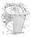
- the apparatus comprises a robust frame indicated as a whole by 10, which is essentially consists of front 12 and rear 14 uprights, front 16 and rear 18 cross members, and side members lower side 20 and upper side 22.
- the conveyor member 24 travels along a route which defines a trough-shaped enclosure 26 ( Figures 2 and 3) constituting a container to receive the objects to treat, such as cork stoppers, whose load or mass is indicated by M in Figures 2 and 3.
- the gauge 26 is open at the top to allow a operator to visually inspect objects at all times subject to processing and possible distribution of a treatment substance on these objects.
- Figures 1 to 3 has been shown by way of example a spray dispenser 28 of a substance of treatment (a lubricant for cork stoppers, by example), which the operator can move according to his judgment along the load M according to the double arrow F1 of the Figure 1 to evenly dose the substance in the charge.
- a substance of treatment a lubricant for cork stoppers, by example
- the path of the conveying member 24 has a shape substantially double U, with an upper branch aisle 30, which defines the trough or container 26, and a lower leg back 32.
- the course of the upper branch 30 of the conveying member 24 has an arcuate shape with a magnitude greater than 180 °.
- This arc shape is defined by a pair of rotary side closing discs 34 which delimit the container 26 on both sides, are located laterally at inside the side edges of the upper branch of the conveying member 24 and are engaged by this branch upper, which causes them to rotate.
- the two discs 34 are carried by a central pin 36 mounted in bearings 38 fixed to the upper beams 22.
- the distance between the discs 34 can be adjusted by sliding along the axis so as to allow the adjustment of the width of the container 26 according to the volume of the load of M objects to be processed.
- Figure 1 the two discs of fence 34 are shown in mixed lines in close positions to obtain a wide container scaled down.
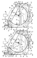
- the upper branch 30 comprises an initial section descending 40 which constitutes a ledge before containment of the load of objects M, an intermediate bottom section 42 with an extent of substantially 180 °, and a section final ascending 44 which ends cantilevered above of the bottom section 42 and along which the objects are trained before falling back to the bottom section 42 according to arrow F3 in FIG. 2.
- the conveying member has a structure similar to that a roller shutter, with a series of slats 46 arranged transversely to the direction of traffic.
- the slats 46 are fixed, by means of plates 48 of preferably at least one chain and preferably three parallel chains 50, including two end chains and one central chain.
- the chains 50 run on respective sprockets which, with the discs 34, define said course substantially double U of the conveying member 24.
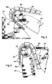
- a group of three driven sprockets 52 ( Figures 2, 3 and 4), wedged on a shaft 54 carried by arm 54 which is part of the frame 10, returns the organ conveyor 24 between the lower branch 32 and the descending section 40 of the upper branch 30;
- a another group of three driven pinions 56 ( Figures 2, 3 and 5), wedged on a shaft 58 carried by arms 60 which make also part of the frame 10, returns the conveying member 24 between the final ascending section 44 of the branch upper 30 and the return branch 32; two others groups of three idler gears 62 and 64 return lower the return branch 32 of the organ carrier 24.
- the section of the return branch 32 returned between the two idler gears 62, 64, indicated by 66 in Figures 1 at 3 and 6, in the preferred embodiment takes a festoon-shaped and acts as a chain tensioner under the effect of the weight of the slats 46.
- a motor-reduction unit 68 with a reversible electric motor 70 and on an output shaft from which is wedged a driving pinion 74 which, through a transmission chain 75 and a driven pinion (not shown), rotates the shaft 58.
- the purpose of the chain drive which in operation normal flows according to arrow F4 in Figure 2, is to not allow the upper branch 30 of the organ conveyor 24 lowers under the weight of the mass M, moving away from the discs 34 and increasing its length to costs of the lower branch back, which would produce a deformation of the trough and compromise its holding capacity.
- the motor 70 is started, the movement of which is transmitted to the conveying member 24 and circulates it in the direction of the arrows F2 in FIG. 2.
- the objects of charge M are shuffled in continuously and during their brewing the operator performs the treatment or treatments required, which he may wish to at all times under his visual surveillance, since the container is not covered.
- the constant radius shape, completely regular and uniform, given by the discs 34 to the container or trough 26, ensures uniform and homogeneous mixing of the objects in any part of their mass.
- the edge initial containment 40 of container 26 has a height as if the conveying member 24 is circulated in the direction F5 opposite to that of normal circulation, the treated objects are dragged up along this edge 40 and project outside, according to arrow F7 of Figure 3, to be collected in a container (not represented).
- the apparatus is preferably provided with a concave plate 82 to collect any dust and fragments descended through slots which are preferably provided for this purpose between the slats 46.
- the plate 82 which is constituted for example by a simple curved sheet of metal or plastic, is located between the bottom section 42 of the upper branch 30 and the bottom section 42 of the lower branch 32 of the conveying member 24.
- the lower beams 20 of the frame 10 are provided with consoles 84 on which tray 82 is all simply placed, which allows it to slide according to arrow F8 in Figure 6 to extract it and rid of discharged R materials.
Landscapes
- Processing Of Solid Wastes (AREA)
- Pretreatment Of Seeds And Plants (AREA)
Abstract
Description
La présente invention concerne un appareil de brassage pour le traitement d'objets en vrac selon le préambule de la revendication 1.The present invention relates to a mixing device for the treatment of loose objects according to the preamble to the claim 1.
L'appareil selon l'invention a été développé dans son application au traitement des bouchons en liège, mais il est susceptible d'application dans le traitement de plusieurs autres objets de petites dimensions.The apparatus according to the invention was developed in its application to the treatment of cork stoppers, but it is likely to apply in the treatment of several other small objects.
Le préambule de la revendication 1 se base sur le document FR-A-2 685 315.The preamble of claim 1 is based on the document FR-A-2 685 315.
Ce document décrit et montre un appareil pour le traitement de bouchons en liège, particulièrement pour l'application par pulvérisation d'un lubrifiant, et notamment d'un liant du type silicone, aux bouchons pendant que ceux-ci sont brassés dans un récipient dont la paroi extérieure est constituée par un blutoir ou tambour entraíné en rotation dans un sens et dans l'autre autour d'un axe horizontal.This document describes and shows an apparatus for treatment cork stoppers, particularly for application by spraying a lubricant, and in particular a binder of the silicone type, to the plugs while these are brewed in a container whose outer wall is constituted by a blutoir or drum driven in rotation in one direction and in the other around a horizontal axis.
Les tambours ou blutoirs pour des traitements de ce genre sont connus depuis de très nombreuses années.Drums or bluishers for such treatment have been known for many, many years.
Par exemple, du document FR-A-515 108 on connaít un procédé et un appareil dans lequel on applique par pulvérisation un dépôt métallique sur des objets maintenus dans un état d'agitation dans un blutoir en rotation autour d'un axe horizontal.For example, from document FR-A-515 108 there is known a process and an apparatus in which a spray is applied metallic deposit on objects kept in a state stirring in a rotating block around an axis horizontal.
Du document FR-A-1 591 077 on connaít un appareil dans lequel, dans un blutoir en rotation autour d'un axe incliné, on applique par pulvérisation une laque sur des petits objets, tels que des curseurs pour fermetures à glissières, maintenus eux aussi dans un état d'agitation.Document FR-A-1,591,077 discloses an apparatus in which, in a rotating block around an axis tilted, a lacquer is applied to small objects, such as sliders for closures slides, also kept in a state of agitation.
Du document US-A-4 831 959 est connu un appareil dans lequel, dans un blutoir en rotation autour d'un axe horizontal, on applique par pulvérisation une résine ou une cire sur des particules de bois pour les revêtir d'une couche de liant en vue de la production d'articles agglomérés.Document US-A-4 831 959 discloses an apparatus in which, in a rotating block around an axis horizontal, a resin or wax on wood particles to coat them with binder layer for the production of articles agglomerates.
Du document DE-A-100 08 512 est connu un appareil dans lequel dans un blutoir en rotation, en forme de malaxeur à béton, on sèche et stérilise des bouchons en liège en les irradiant par des micro-ondes et par des rayons ultraviolets émis par des sources portées par un couvercle qui ferme l'embouchure du malaxeur.Document DE-A-100 08 512 discloses an apparatus in which in a rotating blocker, in the form of a mixer concrete, cork stoppers are dried and sterilized by irradiating with microwaves and rays ultraviolet light emitted by sources carried by a cover which closes the mouth of the mixer.
Tous ces appareils connus, dans lesquels les bouchons ou autres objets sont traités dans un blutoir ou tambour, ne permettent pas à un opérateur de tenir sous surveillance visuelle le traitement des objets et, dans le cas de l'application d'une substance à ces objets pendant leur brassage, ne permettent pas à l'opérateur de doser ces produits sur la base de son expérience: il peut se passer ainsi, spécialement dans le cas d'une matière de qualité inconstante, telle que le liège, que l'application d'une substance de lubrification, d'imprégnation ou d'autre genre s'avère tour à tour excessive ou insuffisante au bout d'un cycle de traitement dans le blutoir. Aussi, même un simple traitement de séchage peut s'avérer excessif ou insuffisant.All these known devices, in which the plugs or other objects are treated in a blutoir or drum, do not not allow an operator to keep under surveillance visual processing of objects and, in the case of applying a substance to these objects during their do not allow the operator to dose these products based on experience: it can happen thus, especially in the case of a quality material inconsistent, such as cork, that applying a lubricating, impregnating or other substance turns out to be excessive or insufficient after a treatment cycle in the blutoir. So even a simple drying treatment may be excessive or insufficient.
Le but de l'invention est celui de réaliser un appareil du genre considéré qui permette à un opérateur de tenir sous contrôle visuel un traitement d'objets dans ledit appareil et de régler les paramètres de ce traitement pendant toute sa durée.The object of the invention is to realize an apparatus of the considered genre that allows an operator to keep under visual control processing of objects in said device and adjust the parameters of this treatment for the entire its duration.
Selon l'invention, ce but est atteint au moyen d'un appareil tel que revendiqué.According to the invention, this object is achieved by means of a device as claimed.
Dans un appareil selon l'invention, l'opérateur peut non seulement surveiller le déroulement du cycle pendant toute sa durée, mais il peut aussi le corriger à tout moment: à titre d'exemple, dans le cas de la lubrification de bouchons en liège, si à un moment donné l'opérateur, qui avec l'appareil selon l'invention a la possibilité d'un contrôle et d'une inspection continus, s'aperçoit que le produit pulvérisé ou versé dans la charge de bouchons est insuffisant, il peut ajouter à la charge davantage de lubrifiant.In a device according to the invention, the operator can not only monitor the progress of the cycle throughout its duration, but it can also correct it at any time: as an example, in the case of the lubrication of cork stoppers, if at some point the operator, who with the apparatus according to the invention has the possibility of a continuous monitoring and inspection, realizes that the product sprayed or poured into the cap load is insufficient, it can add to the load more lubricant.
Dans toute la présente description et dans les revendications, par le terme «traitement» on entend n'importe quel type d'opération de traitement et/ou conditionnement (physique, chimique, de revêtement, d'irradiation, de lubrification, d'imprégnation etc.).Throughout this description and in claims, the term "treatment" means any type of processing operation and / or conditioning (physical, chemical, coating, irradiation, lubrication, impregnation etc.).
Grâce au fait que l'auge est ouverte supérieurement sur toute son extension, l'opérateur est en mesure d'accéder à tout moment aux objets traités et à n'importe quelle zone de leur masse, avant, durant et après la phase de brassage, pour inspecter les objets, contrôler le procédé, évaluer son état d'avancement, prélever des échantillons et intervenir éventuellement pour modifier les paramètres du procédé.Thanks to the fact that the trough is open above on all its extension, the operator is able to access any time to the treated objects and to any zone their mass, before, during and after the brewing phase, to inspect objects, control the process, assess its progress, take samples and possibly intervene to modify the parameters of the process.
L'invention sera mieux éclaircie par la lecture de la description détaillée qui suit, faite avec référence aux dessins annexés, qui en montrent un mode de réalisation préférée, donnée à titre d'exemple non limitatif.The invention will be better clarified by reading the detailed description which follows, made with reference to attached drawings, which show an embodiment thereof preferred, given by way of nonlimiting example.
Sur les dessins:
- la figure 1 est une vue en perspective de l'appareil de brassage,
- la figure 2 est une vue de côté schématique et partiellement arrachée de ce même appareil en condition de fonctionnement normal,
- la figure 3 est une vue de côté analogue avec l'appareil en condition de déchargement des produits traités,
- les figures 4 et 5 sont des vues de détail des zones indiquées par les flèches IV et V, respectivement, sur la figure 1, et
- la figure 6 est une vue en perspective de détail qui montre un plateau de réception de poussières et fragments, situé dans la partie inférieure de l'appareil.
- FIG. 1 is a perspective view of the mixing device,
- FIG. 2 is a diagrammatic and partially cutaway side view of this same device in normal operating conditions,
- FIG. 3 is a similar side view with the apparatus in the condition of discharging the treated products,
- FIGS. 4 and 5 are detailed views of the zones indicated by the arrows IV and V, respectively, in FIG. 1, and
- Figure 6 is a perspective view of detail showing a tray for receiving dust and fragments, located in the lower part of the device.
En se référant aux figures 1 à 3, l'appareil comprend un
robuste bâti indiqué dans son ensemble par 10, qui se
compose essentiellement de montants avant 12 et arrière 14,
de traverses avant 16 et arrière 18, et de longerons
latéraux inférieurs 20 et supérieurs 22.Referring to Figures 1 to 3, the apparatus comprises a
robust frame indicated as a whole by 10, which is
essentially consists of
Dans le bâti se trouve un organe transporteur motorisé en forme de bande continue, indiqué dans son ensemble par 24 et dont la structure préférée sera spécifiée plus loin.In the frame there is a motorized conveying member continuous strip shape, indicated as a whole by 24 and whose preferred structure will be specified later.
L'organe transporteur 24 circule selon un parcours qui
définit une enceinte en forme d'auge 26 (figures 2 et 3)
constituant un récipient pour accueillir les objets à
traiter, tels que des bouchons en liège, dont la charge ou
masse est indiquée par M sur les figures 2 et 3.The
L'auge 26 est ouverte supérieurement pour permettre à un
opérateur d'inspecter visuellement à tout moment les objets
soumis au traitement et l'éventuelle distribution d'une
substance de traitement sur ces objets.The
Sur les figures 1 à 3 a été montré à titre d'exemple un
distributeur par pulvérisation 28 d'une substance de
traitement (un lubrifiant pour bouchons en liège, par
exemple), que l'opérateur peut déplacer selon son jugement
le long de la charge M selon la double flèche F1 de la
figure 1 pour doser uniformément la substance dans la
charge.In Figures 1 to 3 has been shown by way of example a
De préférence, ainsi que montré sur les figures 1 à 3, le
parcours de l'organe transporteur 24 a une forme
sensiblement en double U, avec une branche supérieure
d'allée 30, qui délimite l'auge ou récipient 26, et une
branche inférieure de retour 32. Preferably, as shown in Figures 1 to 3, the
path of the conveying
De façon avantageuse, le parcours de la branche supérieure
30 de l'organe transporteur 24 a une forme en arc de cercle
avec une ampleur supérieure à 180°.Advantageously, the course of the
Cette forme en arc de cercle est définie par une paire de
disques de clôture latéraux rotatifs 34 qui délimitent le
récipient 26 des deux côtés, sont situés latéralement à
l'intérieur des bords latéraux de la branche supérieure de
l'organe transporteur 24 et sont engagés par cette branche
supérieure, qui les entraíne en rotation.This arc shape is defined by a pair of
rotary
Les deux disques 34 sont portés par un axe central 36 monté
dans des paliers 38 fixés aux longerons supérieurs 22.The two
La distance entre les disques 34 peut être ajustée en les
faisant coulisser le long de l'axe de façon à permettre le
réglage de la largeur du récipient 26 selon le volume de la
charge d'objets M à traiter.The distance between the
A titre d'exemple, sur la figure 1 les deux disques de
clôture 34 sont représentés en lignes mixtes dans des
positions rapprochées pour obtenir un récipient de largeur
réduite.For example, in Figure 1 the two discs of
Par rapport au sens de circulation normal de l'organe
transporteur 24, indiqué par les flèches F2 sur la figure
2, la branche supérieure 30 comprend un tronçon initial
descendant 40 qui constitue un rebord avant d'endiguement
de la charge d'objets M, un tronçon de fond intermédiaire
42 avec une ampleur sensiblement de 180°, et un tronçon
final ascendant 44 qui se termine en porte-à-faux au-dessus
du tronçon de fond 42 et le long duquel les objets sont
entraínés avant de retomber vers le tronçon de fond 42
selon la flèche F3 de la figure 2.In relation to the normal direction of circulation of the
De préférence, ainsi que montré sur toutes les figures,
l'organe transporteur a une structure semblable à celle
d'un volet roulant, avec une série de lattes 46 disposées
transversalement par rapport au sens de circulation.Preferably, as shown in all the figures,
the conveying member has a structure similar to that
a roller shutter, with a series of
Ainsi qu'il est mieux montré sur les figures 4 et 5, les
lattes 46 sont fixées, au moyen de plaquettes 48 de
préférence, à au moins une chaíne et de préférence à trois
chaínes parallèles 50, dont deux chaínes d'extrémité et une
chaíne centrale.As best shown in Figures 4 and 5, the
Les chaínes 50 circulent sur des pignons respectifs qui,
avec les disques 34, définissent ledit parcours
sensiblement en double U de l'organe transporteur 24. En
particulier, un groupe de trois pignons entraínés 52
(figures 2, 3 et 4), calés sur un arbre 54 porté par des
bras 54 qui font partie du bâti 10, renvoie l'organe
transporteur 24 entre la branche inférieure 32 et le
tronçon descendant 40 de la branche supérieure 30 ; un
autre groupe de trois pignons entraínés 56 (figures 2, 3 et
5), calés sur un arbre 58 porté par des bras 60 qui font
partie eux aussi du bâti 10, renvoie l'organe transporteur
24 entre le tronçon final ascendant 44 de la branche
supérieure 30 et la branche de retour 32 ; deux autres
groupes de trois pignons fous 62 et 64 renvoient
inférieurement la branche de retour 32 de l'organe
transporteur 24.The
Le tronçon de la branche de retour 32 renvoyé entre les
deux pignons fous 62, 64, indiqué par 66 sur les figures 1
à 3 et 6, dans le mode de réalisation préféré prend une
forme en feston et fait office de tendeur de chaíne sous
l'effet du poids des lattes 46.The section of the
Sur l'un des montants arrière 14 (celui qui n'est pas
visible sur la figure 1) est fixé un groupe moteur-réducteur
68 avec un moteur électrique réversible 70 et sur
un arbre de sortie duquel est calé un pignon menant 74 qui,
par l'entremise d'une chaíne de transmission 75 et d'un
pignon mené (non représenté), entraíne en rotation l'arbre
58.On one of the rear uprights 14 (the one which is not
visible in Figure 1) is fixed a motor-
Ainsi que montré sur les figures 2 et 3, sur les arbres 54
et 58 sont calés des pignons respectifs 76 et 78 de même
diamètre, qui sont reliés entre eux par une chaíne de
transmission 80, grâce à quoi les deux groupes de trois
pignons 52 et 56 sont entraínés en synchronisme.As shown in Figures 2 and 3, on the
Le but de la transmission à chaíne, qui en fonctionnement
normal circule selon la flèche F4 de la figure 2, est de ne
pas permettre que la branche supérieure 30 de l'organe
transporteur 24 s'abaisse sous le poids de la masse M, en
s'éloignant des disques 34 et en augmentant sa longueur aux
dépens de la branche inférieure de retour, ce qui
produirait une déformation de l'auge et compromettrait sa
capacité de retenue.The purpose of the chain drive, which in operation
normal flows according to arrow F4 in Figure 2, is to
not allow the
Pour soumettre à un traitement un lot de bouchons en liège
ou autres objets chargés dans le récipient 26 (la charge
M), on met en marche le moteur 70, dont le mouvement est
transmis à l'organe transporteur 24 et fait circuler celui-ci
dans le sens des flèches F2 de la figure 2.To subject a batch of cork stoppers to treatment
or other objects loaded in container 26 (the load
M), the
De cette façon, les objets de la charge M sont brassés en continu et pendant leur brassage l'opérateur exécute le traitement ou les traitements requis, qu'il peut tenir à tout moment sous sa surveillance visuelle, étant donné que le récipient n'est pas couvert.In this way, the objects of charge M are shuffled in continuously and during their brewing the operator performs the treatment or treatments required, which he may wish to at all times under his visual surveillance, since the container is not covered.
La forme à rayon constant, tout à fait régulière et
uniforme, donnée par les disques 34 au récipient ou auge
26, assure un brassage uniforme et homogène des objets dans
n'importe quelle partie de leur masse. The constant radius shape, completely regular and
uniform, given by the
Avantageusement, mais non nécessairement, le rebord
d'endiguement initial 40 du récipient 26 a une hauteur
telle que si l'organe transporteur 24 est fait circuler
dans le sens F5 contraire à celui de circulation normale,
les objets traités sont entraínés vers le haut le long de
ce rebord 40 et débordent à l'extérieur, selon la flèche F7
de la figure 3, pour être recueillis dans un récipient (non
représenté).Advantageously, but not necessarily, the edge
Avec cette disposition, pour décharger du récipient 26 le
lot d'objets à la fin du traitement, l'opérateur inverse le
mouvement du moteur 70 et l'organe transporteur 24 et la
chaíne 80 circulent en sens inverse, comme indiqué par les
flèches respectives F5 et F6 sur la figure 3.With this arrangement, to discharge from
Ainsi que montré sur les figures 1 à 3 et 6, dans le mode
de réalisation préféré, dans lequel l'organe transporteur
24 est formé par des lattes 46, l'appareil est de
préférence pourvu d'un plateau concave 82 pour recueillir
d'éventuelles poussières et fragments descendus à travers
des fentes qui sont de préférence prévues à cet effet entre
les lattes 46.As shown in Figures 1 to 3 and 6, in the mode
preferred embodiment, in which the conveying
Le plateau 82, qui est constitué par exemple par une simple
feuille cintrée de métal ou de matière plastique, est situé
entre le tronçon de fond 42 de la branche supérieure 30 et
le tronçon de fond 42 de la branche inférieure 32 de
l'organe transporteur 24.The
Les longerons inférieurs 20 du bâti 10 sont pourvus de
consoles 84 sur lesquelles le plateau 82 est tout
simplement posé, ce qui permet de le faire coulisser selon
la flèche F8 de la figure 6 pour l'extraire et le
débarrasser des matières R déchargées.The
Claims (9)
caractérisé en ce qu'il comprend un organe transporteur en forme de bande continue motorisée (24) qui circule selon un parcours définissant une enceinte sous forme d'une auge qui constitue le récipient pour accueillir les objets (M) et est ouverte supérieurement pour permettre l'inspection visuelle et le traitement des objets.Brewing apparatus for the treatment of loose objects, particularly cork stoppers, of the type comprising a container (26) for receiving the objects (M) and any treatment substance, and for brewing this container (26) being delimited by an enclosure (24) animated with a continuous movement to drive the objects (M) upwards from a bottom zone (42) and then let them fall,
characterized in that it comprises a conveyor member in the form of a motorized continuous strip (24) which circulates along a path defining an enclosure in the form of a trough which constitutes the container for accommodating the objects (M) and is open at the top to allow visual inspection and treatment of objects.
Applications Claiming Priority (2)
| Application Number | Priority Date | Filing Date | Title |
|---|---|---|---|
| ITTO20021023 ITTO20021023A1 (en) | 2002-11-27 | 2002-11-27 | MIXER APPARATUS FOR THE TREATMENT OF OBJECTS |
| ITTO20021023 | 2002-11-27 |
Publications (2)
| Publication Number | Publication Date |
|---|---|
| EP1424136A2 true EP1424136A2 (en) | 2004-06-02 |
| EP1424136A3 EP1424136A3 (en) | 2007-04-04 |
Family
ID=32259984
Family Applications (1)
| Application Number | Title | Priority Date | Filing Date |
|---|---|---|---|
| EP03025976A Withdrawn EP1424136A3 (en) | 2002-11-27 | 2003-11-13 | Agitating apparatus for treating objects in bulk, in particular cork stoppers |
Country Status (2)
| Country | Link |
|---|---|
| EP (1) | EP1424136A3 (en) |
| IT (1) | ITTO20021023A1 (en) |
Citations (3)
| Publication number | Priority date | Publication date | Assignee | Title |
|---|---|---|---|---|
| US2104055A (en) * | 1933-08-23 | 1938-01-04 | American Foundry Equip Co | Abrading apparatus |
| US2418934A (en) * | 1944-07-11 | 1947-04-15 | American Foundry Equip Co | Cleaning machine |
| US2909012A (en) * | 1957-01-28 | 1959-10-20 | Wheelabrator Corp | Link and flight bar assembly in a blasting machine |
-
2002
- 2002-11-27 IT ITTO20021023 patent/ITTO20021023A1/en unknown
-
2003
- 2003-11-13 EP EP03025976A patent/EP1424136A3/en not_active Withdrawn
Patent Citations (3)
| Publication number | Priority date | Publication date | Assignee | Title |
|---|---|---|---|---|
| US2104055A (en) * | 1933-08-23 | 1938-01-04 | American Foundry Equip Co | Abrading apparatus |
| US2418934A (en) * | 1944-07-11 | 1947-04-15 | American Foundry Equip Co | Cleaning machine |
| US2909012A (en) * | 1957-01-28 | 1959-10-20 | Wheelabrator Corp | Link and flight bar assembly in a blasting machine |
Also Published As
| Publication number | Publication date |
|---|---|
| EP1424136A3 (en) | 2007-04-04 |
| ITTO20021023A1 (en) | 2004-05-28 |
Similar Documents
| Publication | Publication Date | Title |
|---|---|---|
| EP0192012B1 (en) | Apparatus for continuously and uniformly coating confectionary products | |
| CA2066737C (en) | Process and apparatus for continuous surface treatment of small objects | |
| FR2688710A1 (en) | METHOD AND APPARATUS FOR CONTINUOUS PROCESSING OF PARTICLES. | |
| FR2633262A1 (en) | METHOD AND DEVICE FOR SUCCESSIVELY TRANSPORTING FLAT SHAPED ARTICLES, SUCH AS CANDIES OR THE LIKE | |
| FR2561059A1 (en) | DEVICE FOR SPREADING GRANULAR AND / OR PULVERULENT MATERIAL | |
| FR2658480A1 (en) | APPARATUS FOR STACKING CONTAINERS USED MORE PARTICULARLY IN PACKAGING FACILITIES USING A THERMORETRACTABLE WEB. | |
| FR2483744A1 (en) | DEVICE FOR CIRCULAR FIXING OF PULP PIECES | |
| EP1424136A2 (en) | Agitating apparatus for treating objects in bulk, in particular cork stoppers | |
| EP0132480B1 (en) | Device for the production of sugar products or the like in loose bulk, for instance for homeopathic pharmacy, and products so obtained | |
| EP2342971A1 (en) | Apparatus for preforming bakery dough into a dough strand for division into dough pieces | |
| WO1999058433A1 (en) | Mechanism for automatically directing and dispensing parts | |
| CH664707A5 (en) | PROCESS FOR COATING PENCILS AND INSTALLATION FOR CARRYING OUT SAID METHOD. | |
| EP0125938B1 (en) | Machine for applying a ring of material to containers for pharmaceutical products; selfbreakable ampoules with such a ring | |
| CH617599A5 (en) | ||
| EP0688717A1 (en) | Method and apparatus for conditioning products such as green beans | |
| FR2704779A1 (en) | Machine for spreading a powdery product over a horizontal surface | |
| FR2609598A1 (en) | Machine for working bread dough | |
| BE645955A (en) | ||
| FR2617826A1 (en) | Device for shaking closed containers, particularly bottles of champagne | |
| FR2781689A3 (en) | Solid/liquid separator for use in treatment of semi-liquid manure from livestock, has three chambers with perforated plates through which manure is sieved | |
| FR2539648A1 (en) | APPARATUS FOR OPENING AND CLOSING THE OUTPUT PORT OF A PREPARATION MACHINE | |
| FR2760602A1 (en) | Centrifuge for drying leaf vegetables | |
| FR2794342A1 (en) | Production of spit-baked cakes comprises using a vertical series of mold-bearing spits with hoppers for supplying and collecting dough | |
| BE853721A (en) | IMPROVEMENTS TO EQUIPMENT FOR PROCESSING ARTICLES | |
| DE92594C (en) |
Legal Events
| Date | Code | Title | Description |
|---|---|---|---|
| PUAI | Public reference made under article 153(3) epc to a published international application that has entered the european phase |
Free format text: ORIGINAL CODE: 0009012 |
|
| AK | Designated contracting states |
Kind code of ref document: A2 Designated state(s): AT BE BG CH CY CZ DE DK EE ES FI FR GB GR HU IE IT LI LU MC NL PT RO SE SI SK TR |
|
| AX | Request for extension of the european patent |
Extension state: AL LT LV MK |
|
| PUAL | Search report despatched |
Free format text: ORIGINAL CODE: 0009013 |
|
| AK | Designated contracting states |
Kind code of ref document: A3 Designated state(s): AT BE BG CH CY CZ DE DK EE ES FI FR GB GR HU IE IT LI LU MC NL PT RO SE SI SK TR |
|
| AX | Request for extension of the european patent |
Extension state: AL LT LV MK |
|
| AKX | Designation fees paid | ||
| REG | Reference to a national code |
Ref country code: DE Ref legal event code: 8566 |
|
| STAA | Information on the status of an ep patent application or granted ep patent |
Free format text: STATUS: THE APPLICATION IS DEEMED TO BE WITHDRAWN |
|
| 18D | Application deemed to be withdrawn |
Effective date: 20071005 |