EP1424008B1 - Umluftofen mit einem Radialflammenbrenner - Google Patents
Umluftofen mit einem Radialflammenbrenner Download PDFInfo
- Publication number
- EP1424008B1 EP1424008B1 EP03026975A EP03026975A EP1424008B1 EP 1424008 B1 EP1424008 B1 EP 1424008B1 EP 03026975 A EP03026975 A EP 03026975A EP 03026975 A EP03026975 A EP 03026975A EP 1424008 B1 EP1424008 B1 EP 1424008B1
- Authority
- EP
- European Patent Office
- Prior art keywords
- head
- burner
- flame
- oven according
- burner head
- Prior art date
- Legal status (The legal status is an assumption and is not a legal conclusion. Google has not performed a legal analysis and makes no representation as to the accuracy of the status listed.)
- Expired - Lifetime
Links
- 239000007789 gas Substances 0.000 claims abstract description 15
- 238000010411 cooking Methods 0.000 claims abstract description 14
- UGFAIRIUMAVXCW-UHFFFAOYSA-N Carbon monoxide Chemical compound [O+]#[C-] UGFAIRIUMAVXCW-UHFFFAOYSA-N 0.000 claims abstract description 8
- 239000003546 flue gas Substances 0.000 claims abstract description 8
- 235000013305 food Nutrition 0.000 claims abstract description 6
- 239000000446 fuel Substances 0.000 claims abstract description 5
- 238000009423 ventilation Methods 0.000 claims abstract description 3
- 239000000203 mixture Substances 0.000 claims description 18
- 239000002184 metal Substances 0.000 claims description 12
- 239000000463 material Substances 0.000 claims description 8
- 229910010293 ceramic material Inorganic materials 0.000 claims 1
- 238000002485 combustion reaction Methods 0.000 description 9
- 239000000835 fiber Substances 0.000 description 8
- 230000003247 decreasing effect Effects 0.000 description 3
- 238000002844 melting Methods 0.000 description 3
- 230000008018 melting Effects 0.000 description 3
- 230000005855 radiation Effects 0.000 description 3
- 238000000926 separation method Methods 0.000 description 3
- 239000000919 ceramic Substances 0.000 description 2
- 230000000694 effects Effects 0.000 description 2
- 239000004744 fabric Substances 0.000 description 2
- 239000012530 fluid Substances 0.000 description 2
- 230000009931 harmful effect Effects 0.000 description 2
- 238000013021 overheating Methods 0.000 description 2
- 230000005540 biological transmission Effects 0.000 description 1
- 238000009954 braiding Methods 0.000 description 1
- 235000009508 confectionery Nutrition 0.000 description 1
- 238000009792 diffusion process Methods 0.000 description 1
- 230000007613 environmental effect Effects 0.000 description 1
- 239000002657 fibrous material Substances 0.000 description 1
- 238000003466 welding Methods 0.000 description 1
Images

Classifications
-
- A—HUMAN NECESSITIES
- A21—BAKING; EDIBLE DOUGHS
- A21B—BAKERS' OVENS; MACHINES OR EQUIPMENT FOR BAKING
- A21B1/00—Bakers' ovens
- A21B1/02—Bakers' ovens characterised by the heating arrangements
- A21B1/24—Ovens heated by media flowing therethrough
- A21B1/26—Ovens heated by media flowing therethrough by hot air
-
- F—MECHANICAL ENGINEERING; LIGHTING; HEATING; WEAPONS; BLASTING
- F24—HEATING; RANGES; VENTILATING
- F24C—DOMESTIC STOVES OR RANGES ; DETAILS OF DOMESTIC STOVES OR RANGES, OF GENERAL APPLICATION
- F24C15/00—Details
- F24C15/32—Arrangements of ducts for hot gases, e.g. in or around baking ovens
- F24C15/322—Arrangements of ducts for hot gases, e.g. in or around baking ovens with forced circulation
Definitions
- the present invention relates to a convection oven and more particularly, but not necessarily, a steam convection oven to cook confectionery goods and gastronomic specialties.
- ovens for cooking food products are generally steam convection ovens wherein inside the cooking chamber a heat exchanger is arranged, comprising a spirally wound tube inside which flue gas generally of a gas-fed burner is flowing with a certain speed.
- the burners generally connected to said heat exchanger are generally front flame or torch burners with partial or total premixing of air and fuel.
- the air fuel mixture is supplied by mixing means keeping the air-gas ratio substantially independent from the flow rate.
- a greater calorific power it is sufficient to increase the number of revolutions of the ventilation means connected to said mixing means and consequently the flow rate of the burning mixture is increased without changing the air-gas ratio.
- the flame separation is also due to the geometry of the burner head because, since the burner head must face the heat exchanger inlet, the head diameter should be related to and anyway not greater than the diameter of the heat exchanger which is then wound as a coil. However, this jeopardizes the good operation of the burner because the flame in order not to be separated from the head should have a minimum surface area under which instability takes place.
- Ovens with radial flame burners are also known, two examples of which are disclosed in the European Patent application no. EP 1 321 720 A and in the European Patent application no. EP 0 344 743 A .
- the object of the present invention is to overcome the above mentioned limits.
- a first object of the invention is to provide an oven for cooking food products, provided with a heat exchanger inside the cooking chamber, having a stable flame even when changing the required calorific power.
- Another object of the invention is to avoid that damages to the heat exchanger are generated if the required calorific power is increased.
- a further object to be obtained is that the heat exchanger of the oven generates low values of NOX and other harmful emissions, thus producing flue gas with low environmental impact.
- the burner head zone where the flame sprouts consists of fibrous material having a great number of generally radial micro-channels for exit and ignition of the burning mixture.
- each flame element has a speed vector with prevailing radial direction. This allows to have a great heat exchange surface and therefore a high heat exchange with the combustion chamber enveloping the burner head.
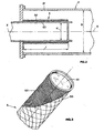
- the forced convection oven generally indicated with numeral 1
- a heat exchanger indicated with 2 that in this embodiment is spirally wound on the theoretical generatrices of a cylinder thus leaving an internal cylindrical room adapted to install a fan 3 adapted to optimise the heat exchange between said exchanger and the cooking chamber 4 used for cooking food products.
- the tube 2 has an inlet straight section 21 having the function of combustion chamber and then a spiral development connected to an end straight section 22.
- the head 5 of a burner generally indicated with numeral 6 is arranged, so that the flue gas generated by the mixture combustion on the burner head, is flowing through the various helices of the exchanger 2 until it goes out from the end section 22 to the outside after having given the heat to the fluid circulating with the aid of fan 3.
- This fluid is an air-steam mixture with variable proportions according to the cooking or baking kind.
- the burner unit 6 has an air inlet tube 62 connected to a mixing valve generally indicated with numeral 63, that as diagrammatically shown in Figure 1 , generally comprises a Venturi tube 64 and the actual valve 68.
- a duct 65 feeds gas which is then mixed with air coming from inlet 62 and delivered to the inlet 641 of the Venturi tube 64.
- the air-gas mixture reaches the fan 66 which then generates the air-gas flow rate coming to the burner head 5 on which the flame is fired.
- valve 68 when air pressure due to the increase of flow rate generated by the fan 66 is decreased, causes a corresponding greater opening of the gas-feeding valve so that the amount of gas flowing through the tube 65 is increased.
- a control panel indicated with numeral 71 reads the temperature Tf inside the oven and according to the deviation of the temperature reading relative to the preset one, emits a signal ⁇ T to the fan 66 to change accordingly the number of revolutions.
- the burner head must be arranged near the inlet of the heat exchanger 2, so that all the flue gas can flow through said exchanger. Only in this way the heat exchange inside the cooking chamber can be optimised.
- this causes the already mentioned drawbacks that the present invention aims at overcoming.
- the present invention provides a burner having a combustion head where the flame has a radial development almost along the entire length of the head.
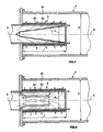
- the burner according to the invention is a burner wherein the head has essentially a symmetric axial shape and in the illustrated embodiment has, more particularly, a cylindrical shape with a diameter indicated with d of such dimensions that the burner head 5 can be easily inserted inside the first section 21 of the exchanger 2 as shown in Figure 2 .
- the diameter D of the section 21 of exchanger 2 is almost the double of diameter d of the burner head 5.
- an end plug 51 is provided in the burner head 5 so that the entire mixture is being burnt on the cylindrical surface of the length l and therefore along the radial direction of head 5, and not along the axial direction, i.e. along axis X of said head.
- This dimension of the burner head allows the flame to remain anchored to the surface 52 constituting the flame sprouting surface that is made with a special material as described hereinafter.
- a strong radiation due to over-heating of the outer surface of the burner head is then transmitted to the section 21 of the exchanger 2, that is to the combustion chamber and consequently the flue gas, when coming out and being conveyed to the first bend 23 of the spirally wound heat exchanger (see Figure 1 ), is not so hot to cause the above mentioned harmful effects concerning the front flame burners or non-radiating burners.
- the diameter of the combustion chamber cannot be designed of any size just to avoid big obstruction zones to the air circulated by the fan 3, causing a poor cooking evenness of the food products and an excessive increase of temperature of the material of the combustion chamber.
- the flame sprouting surface which in this embodiment is a generally cylindrical surface with radial development, this is obtained by inserting a fabric braiding of metal fibre such as Acotech®, on a support core that in this embodiment comprises a metal lathing forming a tubular mesh.
- each flame element has a generally radial development because the speed vector to be associated to the direction of diffusion of each flame element has a radial direction.
- the metal fibre surface constitutes also the flame sprouting surface and it is known that the flame anchorage to said surface depends on the dimensional ratio between length and diameter of the micro-channel.
- a head In order to make operatively a head according to the invention, one starts from a cylindrical or almost cylindrical core, made with metal lathing forming a tubular mesh 53. A plug 51 is then end-welded to said lathing. The metal fibre 52 is subsequently inserted, for instance consisting of the metal fibre Acotech®, fixing it with some welding spots on the core 53 so as to obtain anchorage between metal fibre and core.
- the metal fibre relates to an embodiment of the invention only, but equivalent results may be obtained if the metal fibre is replaced by another material such as ceramics.
- ceramics should also be fibrous or any way have micro-channels allowing the flame to sprout on its surface. Indeed, such a material is required to warrant first of all an optimal behaviour at high temperature, having micro-channels, adapted to make a generally cylindrical surface forming the burner head and having the feature of radially arranged micro-channels and micro-holes so as to obtain a flame distribution generally in the same way as above described.
- a constructional variation of the invention provides for application of a diffuser of the combusting mixture inside the burner head.
- a suitable kind of said diffuser is shown in Figure 4 and indicated with numeral 7.
- said diffuser may take any suitable shape.
Landscapes
- Engineering & Computer Science (AREA)
- Chemical & Material Sciences (AREA)
- Combustion & Propulsion (AREA)
- Mechanical Engineering (AREA)
- General Engineering & Computer Science (AREA)
- Life Sciences & Earth Sciences (AREA)
- Food Science & Technology (AREA)
- Gas Burners (AREA)
Claims (9)
- Ein Zwangskonvektionsofen (1) zum Garen von Nahrungsmittelprodukten, Folgendes umfassend:- eine Garkammer (4) mit internen Wärmetauschermitteln (2), die wenigstens ein gewundenes Rohr umfassen, durch das der Fluss der verbrannten Gase strömt;- einen Brenner (6) mit Mitteln (64) zur Vermischung von Luft und Brennstoff;- Belüftungsmittel (66), die geeignet sind, den gemäß einer geforderten Wärmeleistung für den Brenner erforderlichen Durchfluss des Luft-/Brennstoffgemischs zu liefern,wobei der besagte Brenner (6) einen Kopf (5) von im Wesentlichen axial symmetrischer Form aufweist und seine Flammenfrontfläche hauptsächlich in axialer Richtung des Kopfs angeordnet ist, und wobei der Kopf eine größere Länge aufweist als sein Quermaß, und der Geschwindigkeitsvektor besagter Flamme im Wesentlichen in radiale Richtungen verläuft, dadurch gekennzeichnet, dass der besagte Brennerkopf innerhalb des geraden Einlassbereichs des besagten Rohrs angeordnet ist, sowie dadurch, dass seine Flammenentwicklungsfläche aus einem Material mit einer Reihe radial verlaufender Mikrokanalauslässe besteht.
- Ofen gemäß Patentanspruch 1), dadurch gekennzeichnet, dass das Verhältnis zwischen Durchmesser und Länge des besagten Brennerkopfs, der durch die Flamme erfasst wird, gleich oder kleiner als 1:2 ist.
- Ofen gemäß Patentanspruch 1), dadurch gekennzeichnet, dass die besagte Flammenentwicklungsfläche durch einen im Wesentlichen zylindrischen Kern (53) gehalten wird.
- Ofen gemäß Patentanspruch 3), dadurch gekennzeichnet, dass der besagte zylindrische Kern (53) ein Streckmetall ist, das ein röhrenförmiges Netz bildet.
- Ofen gemäß eines jeglichen der vorstehenden Patentansprüche, dadurch gekennzeichnet, dass das Ende des besagten Brennerkopfs durch einen Stopfen (51) verschlossen ist.
- Ofen gemäß Patentanspruch 5), dadurch gekennzeichnet, dass der besagte Stopfen (51) fest am besagten Kern (53) befestigt ist.
- Ofen gemäß Patentanspruch 1), dadurch gekennzeichnet, dass das besagte Material des besagten Brennerkopfs aus maschenartig miteinander verflochtenen Metallfasern besteht, die eine Vielzahl der besagten Mikrokanäle bilden.
- Ofen gemäß Patentanspruch 1) dadurch gekennzeichnet, dass das besagte Material des besagten Brennerkopfs ein Keramikfasermaterial oder ein anderes Material ist, das geeignet ist, eine Vielzahl von Mikrokanälen zu bilden.
- Ofen gemäß eines jeglichen der vorstehenden Patentansprüche, dadurch gekennzeichnet, dass der besagte Brennerkopf (5) innen mit einem Brennstoffgemisch-Diffusor (7, 8) versehen ist, der geeignet ist, dieses Gemisch im Wesentlichen gleichmäßig über die Länge (I) des besagten Kopfes zu verteilen.
Applications Claiming Priority (2)
| Application Number | Priority Date | Filing Date | Title |
|---|---|---|---|
| IT000260A ITVI20020260A1 (it) | 2002-11-28 | 2002-11-28 | Forno a convenzione con bruciatore a fiamma radiale. |
| ITVI20020260 | 2002-11-28 |
Publications (4)
| Publication Number | Publication Date |
|---|---|
| EP1424008A2 EP1424008A2 (de) | 2004-06-02 |
| EP1424008A3 EP1424008A3 (de) | 2005-07-13 |
| EP1424008A9 EP1424008A9 (de) | 2006-04-12 |
| EP1424008B1 true EP1424008B1 (de) | 2010-06-16 |
Family
ID=32259991
Family Applications (1)
| Application Number | Title | Priority Date | Filing Date |
|---|---|---|---|
| EP03026975A Expired - Lifetime EP1424008B1 (de) | 2002-11-28 | 2003-11-26 | Umluftofen mit einem Radialflammenbrenner |
Country Status (4)
| Country | Link |
|---|---|
| EP (1) | EP1424008B1 (de) |
| AT (1) | ATE471077T1 (de) |
| DE (1) | DE60332986D1 (de) |
| IT (1) | ITVI20020260A1 (de) |
Families Citing this family (4)
| Publication number | Priority date | Publication date | Assignee | Title |
|---|---|---|---|---|
| ITMO20080069A1 (it) * | 2008-03-10 | 2009-09-11 | Worgas Bruciatori Srl | Bruciatore dotato di mezzi di riduzione del rumore |
| WO2010012493A2 (de) * | 2008-07-31 | 2010-02-04 | Jaroslav Klouda | Wärmetauschersystem, sowie hiermit ausgestattetes gasbeheiztes gerät |
| ITUB20152781A1 (it) * | 2015-08-03 | 2017-02-03 | Unox Spa | Forno di cottura ad uso alimentare con bruciatore a gas a pre-miscelazione |
| US12031727B2 (en) | 2021-03-05 | 2024-07-09 | Electrolux Home Products, Inc. | Oven bake heating channel exchange system |
Citations (2)
| Publication number | Priority date | Publication date | Assignee | Title |
|---|---|---|---|---|
| EP0245084A1 (de) * | 1986-05-08 | 1987-11-11 | Aos Holding Company | Verbrennungselement für einen Strahlungsenergiebrenner |
| US20020092482A1 (en) * | 2000-01-10 | 2002-07-18 | Bodnar Timothy J. | Burner |
Family Cites Families (7)
| Publication number | Priority date | Publication date | Assignee | Title |
|---|---|---|---|---|
| US4648377A (en) * | 1986-05-01 | 1987-03-10 | Hobart Corporation | Gas convection oven and heat exchanger therefor |
| IT1220754B (it) * | 1988-06-01 | 1990-06-21 | Zanussi Grandi Impianti Spa | Forno di cottura a gas a convezione forzata |
| US4867132A (en) * | 1988-11-23 | 1989-09-19 | Garland Commercial Industries, Inc. | Gas fired convection oven with improved air delivery and heat exchange structure |
| IT1253697B (it) * | 1991-08-05 | 1995-08-22 | Zanussi Grandi Impianti Spa | Forno di cottura a gas a convezione forzata. |
| NL1014044C2 (nl) * | 2000-01-10 | 2001-07-19 | Levens Group B V | Door gasbrander verwarmde oven. |
| IT1315481B1 (it) * | 2000-07-25 | 2003-02-18 | Gierre Srl | Forno a convezione forzata per la cottura di alimenti |
| DE10162952C5 (de) * | 2001-12-20 | 2007-05-16 | Convotherm Elektrogeraete | Wärmetauschereinrichtung |
-
2002
- 2002-11-28 IT IT000260A patent/ITVI20020260A1/it unknown
-
2003
- 2003-11-26 AT AT03026975T patent/ATE471077T1/de not_active IP Right Cessation
- 2003-11-26 DE DE60332986T patent/DE60332986D1/de not_active Expired - Lifetime
- 2003-11-26 EP EP03026975A patent/EP1424008B1/de not_active Expired - Lifetime
Patent Citations (2)
| Publication number | Priority date | Publication date | Assignee | Title |
|---|---|---|---|---|
| EP0245084A1 (de) * | 1986-05-08 | 1987-11-11 | Aos Holding Company | Verbrennungselement für einen Strahlungsenergiebrenner |
| US20020092482A1 (en) * | 2000-01-10 | 2002-07-18 | Bodnar Timothy J. | Burner |
Also Published As
| Publication number | Publication date |
|---|---|
| DE60332986D1 (de) | 2010-07-29 |
| EP1424008A2 (de) | 2004-06-02 |
| ITVI20020260A1 (it) | 2004-05-29 |
| EP1424008A3 (de) | 2005-07-13 |
| EP1424008A9 (de) | 2006-04-12 |
| ATE471077T1 (de) | 2010-07-15 |
Similar Documents
| Publication | Publication Date | Title |
|---|---|---|
| US4519770A (en) | Firetube boiler heater system | |
| US4298333A (en) | Industrial heating installation and method of operation | |
| CA2974190C (en) | Modulating burner | |
| US8591222B2 (en) | Gas-fired furnace with cavity burners | |
| US9605871B2 (en) | Furnace burner radiation shield | |
| US20030084896A1 (en) | Flexible gas-fired heat exchanger system | |
| US6024083A (en) | Radiant tube burner nozzle | |
| US20200096192A1 (en) | Inward fired ultra low nox insulating burner flange | |
| JP2004144468A (ja) | 多段制御を具現するガス燃焼バーナ | |
| US3195609A (en) | Self stabilizing radiant tube burner | |
| US6918759B2 (en) | Premixed combustion gas burner having separated fire hole units | |
| US20170009982A1 (en) | Ultra low nox insulating burner without collar | |
| EP1424008B1 (de) | Umluftofen mit einem Radialflammenbrenner | |
| US7052273B2 (en) | Premixed fuel burner assembly | |
| US12222103B2 (en) | Modular burner and furnace including this burner | |
| CA2099227C (en) | Standing pilot furnace with vented vestibule | |
| US7980850B2 (en) | Self-recuperated, low NOx flat radiant panel heater | |
| US7017571B2 (en) | Heat exchanger device | |
| USRE37128E1 (en) | Standing pilot furnace with vented vestibule | |
| JP2005521026A (ja) | バーナーに使用する着脱自在な点火ポートプラグ | |
| US11287128B2 (en) | Inward fired low NOX premix burner | |
| US20250075978A1 (en) | Gas furnace with heat shielding plate | |
| US10429065B2 (en) | Low NOx gas burners with carryover ignition | |
| HU186436B (en) | Gas burner of flat flame | |
| US20200173689A1 (en) | Inward fired low nox premix burner |
Legal Events
| Date | Code | Title | Description |
|---|---|---|---|
| PUAI | Public reference made under article 153(3) epc to a published international application that has entered the european phase |
Free format text: ORIGINAL CODE: 0009012 |
|
| AK | Designated contracting states |
Kind code of ref document: A2 Designated state(s): AT BE BG CH CY CZ DE DK EE ES FI FR GB GR HU IE IT LI LU MC NL PT RO SE SI SK TR |
|
| AX | Request for extension of the european patent |
Extension state: AL LT LV MK |
|
| PUAL | Search report despatched |
Free format text: ORIGINAL CODE: 0009013 |
|
| AK | Designated contracting states |
Kind code of ref document: A3 Designated state(s): AT BE BG CH CY CZ DE DK EE ES FI FR GB GR HU IE IT LI LU MC NL PT RO SE SI SK TR |
|
| AX | Request for extension of the european patent |
Extension state: AL LT LV MK |
|
| RAP1 | Party data changed (applicant data changed or rights of an application transferred) |
Owner name: IK-INTERKLIMAT SPA |
|
| 17P | Request for examination filed |
Effective date: 20060112 |
|
| AKX | Designation fees paid |
Designated state(s): AT BE BG CH CY CZ DE DK EE ES FI FR GB GR HU IE IT LI LU MC NL PT RO SE SI SK TR |
|
| AXX | Extension fees paid |
Extension state: MK Payment date: 20060112 Extension state: LT Payment date: 20060112 Extension state: LV Payment date: 20060112 Extension state: AL Payment date: 20060112 |
|
| GRAP | Despatch of communication of intention to grant a patent |
Free format text: ORIGINAL CODE: EPIDOSNIGR1 |
|
| GRAC | Information related to communication of intention to grant a patent modified |
Free format text: ORIGINAL CODE: EPIDOSCIGR1 |
|
| GRAS | Grant fee paid |
Free format text: ORIGINAL CODE: EPIDOSNIGR3 |
|
| GRAA | (expected) grant |
Free format text: ORIGINAL CODE: 0009210 |
|
| AK | Designated contracting states |
Kind code of ref document: B1 Designated state(s): AT BE BG CH CY CZ DE DK EE ES FI FR GB GR HU IE IT LI LU MC NL PT RO SE SI SK TR |
|
| AX | Request for extension of the european patent |
Extension state: AL LT LV MK |
|
| REG | Reference to a national code |
Ref country code: CH Ref legal event code: EP |
|
| REG | Reference to a national code |
Ref country code: IE Ref legal event code: FG4D |
|
| REF | Corresponds to: |
Ref document number: 60332986 Country of ref document: DE Date of ref document: 20100729 Kind code of ref document: P |
|
| REG | Reference to a national code |
Ref country code: NL Ref legal event code: VDEP Effective date: 20100616 |
|
| PG25 | Lapsed in a contracting state [announced via postgrant information from national office to epo] |
Ref country code: SE Free format text: LAPSE BECAUSE OF FAILURE TO SUBMIT A TRANSLATION OF THE DESCRIPTION OR TO PAY THE FEE WITHIN THE PRESCRIBED TIME-LIMIT Effective date: 20100616 |
|
| LTIE | Lt: invalidation of european patent or patent extension |
Effective date: 20100616 |
|
| PG25 | Lapsed in a contracting state [announced via postgrant information from national office to epo] |
Ref country code: AT Free format text: LAPSE BECAUSE OF FAILURE TO SUBMIT A TRANSLATION OF THE DESCRIPTION OR TO PAY THE FEE WITHIN THE PRESCRIBED TIME-LIMIT Effective date: 20100616 Ref country code: SI Free format text: LAPSE BECAUSE OF FAILURE TO SUBMIT A TRANSLATION OF THE DESCRIPTION OR TO PAY THE FEE WITHIN THE PRESCRIBED TIME-LIMIT Effective date: 20100616 Ref country code: FI Free format text: LAPSE BECAUSE OF FAILURE TO SUBMIT A TRANSLATION OF THE DESCRIPTION OR TO PAY THE FEE WITHIN THE PRESCRIBED TIME-LIMIT Effective date: 20100616 |
|
| PG25 | Lapsed in a contracting state [announced via postgrant information from national office to epo] |
Ref country code: CY Free format text: LAPSE BECAUSE OF FAILURE TO SUBMIT A TRANSLATION OF THE DESCRIPTION OR TO PAY THE FEE WITHIN THE PRESCRIBED TIME-LIMIT Effective date: 20100616 Ref country code: GR Free format text: LAPSE BECAUSE OF FAILURE TO SUBMIT A TRANSLATION OF THE DESCRIPTION OR TO PAY THE FEE WITHIN THE PRESCRIBED TIME-LIMIT Effective date: 20100917 |
|
| PG25 | Lapsed in a contracting state [announced via postgrant information from national office to epo] |
Ref country code: NL Free format text: LAPSE BECAUSE OF FAILURE TO SUBMIT A TRANSLATION OF THE DESCRIPTION OR TO PAY THE FEE WITHIN THE PRESCRIBED TIME-LIMIT Effective date: 20100616 Ref country code: EE Free format text: LAPSE BECAUSE OF FAILURE TO SUBMIT A TRANSLATION OF THE DESCRIPTION OR TO PAY THE FEE WITHIN THE PRESCRIBED TIME-LIMIT Effective date: 20100616 |
|
| PG25 | Lapsed in a contracting state [announced via postgrant information from national office to epo] |
Ref country code: PT Free format text: LAPSE BECAUSE OF FAILURE TO SUBMIT A TRANSLATION OF THE DESCRIPTION OR TO PAY THE FEE WITHIN THE PRESCRIBED TIME-LIMIT Effective date: 20101018 Ref country code: RO Free format text: LAPSE BECAUSE OF FAILURE TO SUBMIT A TRANSLATION OF THE DESCRIPTION OR TO PAY THE FEE WITHIN THE PRESCRIBED TIME-LIMIT Effective date: 20100616 Ref country code: BE Free format text: LAPSE BECAUSE OF FAILURE TO SUBMIT A TRANSLATION OF THE DESCRIPTION OR TO PAY THE FEE WITHIN THE PRESCRIBED TIME-LIMIT Effective date: 20100616 Ref country code: SK Free format text: LAPSE BECAUSE OF FAILURE TO SUBMIT A TRANSLATION OF THE DESCRIPTION OR TO PAY THE FEE WITHIN THE PRESCRIBED TIME-LIMIT Effective date: 20100616 Ref country code: CZ Free format text: LAPSE BECAUSE OF FAILURE TO SUBMIT A TRANSLATION OF THE DESCRIPTION OR TO PAY THE FEE WITHIN THE PRESCRIBED TIME-LIMIT Effective date: 20100616 |
|
| PLBE | No opposition filed within time limit |
Free format text: ORIGINAL CODE: 0009261 |
|
| STAA | Information on the status of an ep patent application or granted ep patent |
Free format text: STATUS: NO OPPOSITION FILED WITHIN TIME LIMIT |
|
| PG25 | Lapsed in a contracting state [announced via postgrant information from national office to epo] |
Ref country code: DK Free format text: LAPSE BECAUSE OF FAILURE TO SUBMIT A TRANSLATION OF THE DESCRIPTION OR TO PAY THE FEE WITHIN THE PRESCRIBED TIME-LIMIT Effective date: 20100616 |
|
| 26N | No opposition filed |
Effective date: 20110317 |
|
| REG | Reference to a national code |
Ref country code: DE Ref legal event code: R119 Ref document number: 60332986 Country of ref document: DE |
|
| REG | Reference to a national code |
Ref country code: DE Ref legal event code: R119 Ref document number: 60332986 Country of ref document: DE |
|
| PG25 | Lapsed in a contracting state [announced via postgrant information from national office to epo] |
Ref country code: MC Free format text: LAPSE BECAUSE OF NON-PAYMENT OF DUE FEES Effective date: 20101130 |
|
| REG | Reference to a national code |
Ref country code: CH Ref legal event code: PL |
|
| REG | Reference to a national code |
Ref country code: DE Ref legal event code: R097 Ref document number: 60332986 Country of ref document: DE Effective date: 20110316 Ref country code: DE Ref legal event code: R097 Ref document number: 60332986 Country of ref document: DE Effective date: 20110317 |
|
| GBPC | Gb: european patent ceased through non-payment of renewal fee |
Effective date: 20101126 |
|
| PG25 | Lapsed in a contracting state [announced via postgrant information from national office to epo] |
Ref country code: CH Free format text: LAPSE BECAUSE OF NON-PAYMENT OF DUE FEES Effective date: 20101130 Ref country code: LI Free format text: LAPSE BECAUSE OF NON-PAYMENT OF DUE FEES Effective date: 20101130 |
|
| PGFP | Annual fee paid to national office [announced via postgrant information from national office to epo] |
Ref country code: IT Payment date: 20101129 Year of fee payment: 8 |
|
| REG | Reference to a national code |
Ref country code: FR Ref legal event code: ST Effective date: 20110801 |
|
| PG25 | Lapsed in a contracting state [announced via postgrant information from national office to epo] |
Ref country code: FR Free format text: LAPSE BECAUSE OF NON-PAYMENT OF DUE FEES Effective date: 20101130 Ref country code: IE Free format text: LAPSE BECAUSE OF NON-PAYMENT OF DUE FEES Effective date: 20101126 |
|
| PG25 | Lapsed in a contracting state [announced via postgrant information from national office to epo] |
Ref country code: GB Free format text: LAPSE BECAUSE OF NON-PAYMENT OF DUE FEES Effective date: 20101126 |
|
| PG25 | Lapsed in a contracting state [announced via postgrant information from national office to epo] |
Ref country code: LU Free format text: LAPSE BECAUSE OF NON-PAYMENT OF DUE FEES Effective date: 20101126 Ref country code: BG Free format text: LAPSE BECAUSE OF FAILURE TO SUBMIT A TRANSLATION OF THE DESCRIPTION OR TO PAY THE FEE WITHIN THE PRESCRIBED TIME-LIMIT Effective date: 20100616 Ref country code: HU Free format text: LAPSE BECAUSE OF FAILURE TO SUBMIT A TRANSLATION OF THE DESCRIPTION OR TO PAY THE FEE WITHIN THE PRESCRIBED TIME-LIMIT Effective date: 20101217 |
|
| PG25 | Lapsed in a contracting state [announced via postgrant information from national office to epo] |
Ref country code: TR Free format text: LAPSE BECAUSE OF FAILURE TO SUBMIT A TRANSLATION OF THE DESCRIPTION OR TO PAY THE FEE WITHIN THE PRESCRIBED TIME-LIMIT Effective date: 20100616 |
|
| PG25 | Lapsed in a contracting state [announced via postgrant information from national office to epo] |
Ref country code: DE Free format text: LAPSE BECAUSE OF NON-PAYMENT OF DUE FEES Effective date: 20110531 |
|
| PG25 | Lapsed in a contracting state [announced via postgrant information from national office to epo] |
Ref country code: IT Free format text: LAPSE BECAUSE OF NON-PAYMENT OF DUE FEES Effective date: 20121126 |
|
| PG25 | Lapsed in a contracting state [announced via postgrant information from national office to epo] |
Ref country code: BG Free format text: LAPSE BECAUSE OF FAILURE TO SUBMIT A TRANSLATION OF THE DESCRIPTION OR TO PAY THE FEE WITHIN THE PRESCRIBED TIME-LIMIT Effective date: 20100916 |
|
| PG25 | Lapsed in a contracting state [announced via postgrant information from national office to epo] |
Ref country code: ES Free format text: LAPSE BECAUSE OF FAILURE TO SUBMIT A TRANSLATION OF THE DESCRIPTION OR TO PAY THE FEE WITHIN THE PRESCRIBED TIME-LIMIT Effective date: 20100927 |