EP1423675B1 - Method and device for measuring the viscosity of a liquid - Google Patents
Method and device for measuring the viscosity of a liquid Download PDFInfo
- Publication number
- EP1423675B1 EP1423675B1 EP02760127A EP02760127A EP1423675B1 EP 1423675 B1 EP1423675 B1 EP 1423675B1 EP 02760127 A EP02760127 A EP 02760127A EP 02760127 A EP02760127 A EP 02760127A EP 1423675 B1 EP1423675 B1 EP 1423675B1
- Authority
- EP
- European Patent Office
- Prior art keywords
- temperature
- viscosity
- liquid
- sensor
- measured
- Prior art date
- Legal status (The legal status is an assumption and is not a legal conclusion. Google has not performed a legal analysis and makes no representation as to the accuracy of the status listed.)
- Expired - Lifetime
Links
- 239000007788 liquid Substances 0.000 title claims abstract description 30
- 238000000034 method Methods 0.000 title claims abstract description 20
- 238000005259 measurement Methods 0.000 claims abstract description 7
- 230000002123 temporal effect Effects 0.000 claims description 2
- 239000003921 oil Substances 0.000 description 14
- 239000010705 motor oil Substances 0.000 description 10
- 230000008859 change Effects 0.000 description 7
- 230000008901 benefit Effects 0.000 description 3
- 238000001816 cooling Methods 0.000 description 3
- 230000001419 dependent effect Effects 0.000 description 3
- 238000011156 evaluation Methods 0.000 description 3
- 230000017525 heat dissipation Effects 0.000 description 3
- 238000009529 body temperature measurement Methods 0.000 description 2
- 230000008569 process Effects 0.000 description 2
- 238000000926 separation method Methods 0.000 description 2
- 238000012935 Averaging Methods 0.000 description 1
- 230000015572 biosynthetic process Effects 0.000 description 1
- 238000004364 calculation method Methods 0.000 description 1
- 238000012512 characterization method Methods 0.000 description 1
- 238000010276 construction Methods 0.000 description 1
- 230000006866 deterioration Effects 0.000 description 1
- 238000010586 diagram Methods 0.000 description 1
- 238000001914 filtration Methods 0.000 description 1
- 239000012530 fluid Substances 0.000 description 1
- 238000010438 heat treatment Methods 0.000 description 1
- 239000000463 material Substances 0.000 description 1
- 230000007246 mechanism Effects 0.000 description 1
- 238000012544 monitoring process Methods 0.000 description 1
- 230000009467 reduction Effects 0.000 description 1
Images
Classifications
-
- G—PHYSICS
- G01—MEASURING; TESTING
- G01N—INVESTIGATING OR ANALYSING MATERIALS BY DETERMINING THEIR CHEMICAL OR PHYSICAL PROPERTIES
- G01N33/00—Investigating or analysing materials by specific methods not covered by groups G01N1/00 - G01N31/00
- G01N33/26—Oils; Viscous liquids; Paints; Inks
- G01N33/28—Oils, i.e. hydrocarbon liquids
-
- G—PHYSICS
- G01—MEASURING; TESTING
- G01N—INVESTIGATING OR ANALYSING MATERIALS BY DETERMINING THEIR CHEMICAL OR PHYSICAL PROPERTIES
- G01N11/00—Investigating flow properties of materials, e.g. viscosity, plasticity; Analysing materials by determining flow properties
-
- G—PHYSICS
- G01—MEASURING; TESTING
- G01N—INVESTIGATING OR ANALYSING MATERIALS BY DETERMINING THEIR CHEMICAL OR PHYSICAL PROPERTIES
- G01N11/00—Investigating flow properties of materials, e.g. viscosity, plasticity; Analysing materials by determining flow properties
- G01N2011/0006—Calibrating, controlling or cleaning viscometers
- G01N2011/0013—Temperature compensation
Definitions
- the physical oil parameters determined in these methods are generally temperature-dependent, so that a temperature compensation calculation is necessary to determine a comparison value.
- a method for assessing the deterioration of engine oil is known in which by a sensor, the oil viscosity of the engine oil is measured and in which by a sensor, the oil viscosity of the engine oil is measured and in which the sensor for oil viscosity measurement a temperature sensor is assigned for the simultaneous determination of the oil temperature, wherein the oil viscosity and the oil temperature is measured in the cooling phase of the engine after its shutdown.
- the inventive method and apparatus according to the invention with the features of the independent claims has the advantage that at any time, that is not only in the cooling phase of the engine, the oil viscosity can be measured. Furthermore, the method and the device according to the invention is characterized in that it is possible vorteihaft introduced to perform a more accurate determination of the viscosity.
- a viscosity measurement by means of a viscosity sensor can be used to assess the current state of the liquid.
- the viscosity ⁇ is usually a strongly temperature-dependent variable, it is indispensable at the same time to determine the temperature T by a temperature sensor.
- the different temperature of the liquid caused by the spatial separation of the viscosity sensor and the temperature sensor at the location of the viscosity sensor and at the location of the temperature sensor is due to a temperature gradient in the liquid.
- Such a temperature gradient preferably occurs in the case of strong heat supply or heat dissipation in the liquid to be monitored. Therefore, the method according to the invention and the device according to the invention can be used advantageously, in particular for large temperature gradients, because there the viscosity measurements carried out without the method according to the invention or the device according to the invention would be particularly inaccurate.
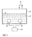
- FIG. 1 shows a schematic diagram of the measuring arrangement.
- FIG. 1 shows a container 10 with a liquid 12.
- a viscosity sensor 20 and a temperature sensor 30 is provided in the container 10 and on the container 10. Both the viscosity sensor 20 and the temperature sensor 30 are connected to an evaluation unit 40.
- the reference numeral 14 By means of two arrows designated by the reference numeral 14, it is indicated that, in the case of the container 10 shown in FIG. 1, there is a supply and / or a removal of heat and / or the liquid 12 due to operation.
- the liquid 12 can be moved in the container 10, for example by circulation pumps or by convection, wherein due to particularly cold or hot spots of the container 10, a temperature gradient in the liquid 12 is formed.
- the spatial separation of the viscosity sensor 20 from the temperature sensor 30 causes the temperature of the liquid 12 at the spatial position of the viscosity sensor 20 to be at that position of the temperature sensor 30 deviates. Accordingly, the temperature T 30 measured by the temperature sensor 30 does not represent the (in principle unknown) temperature T 20 of the liquid 12 at the location of the viscosity sensor 20.
- the present invention describes a method for determining valid measured value pairs.
- the measure or measure should now be defined so that falling below a certain threshold S or a certain threshold indicates an acceptable reduction of the temperature gradient.
- the physical background of the proposed method is the assumption that, due to the thermal compensation processes, smaller changes in the local temperature over time can lead to smaller spatial temperature gradients.
- the amount of the time difference quotient of the temperature measurement value is determined as a measure of the inhomogeneity of the temperature of the liquid. If the measure Z k determined in this way is below a predetermined threshold S, the temperature distribution is regarded as sufficiently homogeneous.
- a plurality of temperature sensors 30 can be arranged spatially separated.
- a plurality of such temperature sensors are provided according to the invention at different locations, in particular of the container 10.
- the temperature at the location of the viscosity sensor 20 may be estimated by averaging, for example.
Landscapes
- Chemical & Material Sciences (AREA)
- Health & Medical Sciences (AREA)
- Life Sciences & Earth Sciences (AREA)
- Immunology (AREA)
- Analytical Chemistry (AREA)
- Biochemistry (AREA)
- General Health & Medical Sciences (AREA)
- General Physics & Mathematics (AREA)
- Physics & Mathematics (AREA)
- Pathology (AREA)
- Engineering & Computer Science (AREA)
- Chemical Kinetics & Catalysis (AREA)
- General Chemical & Material Sciences (AREA)
- Oil, Petroleum & Natural Gas (AREA)
- Food Science & Technology (AREA)
- Medicinal Chemistry (AREA)
- Investigating Or Analyzing Materials Using Thermal Means (AREA)
Abstract
Description
Es sind software-basierte Systeme zur Anzeige eines notwendigen Motorölwechsels bei Kraftfahrzeugen bekannt, von denen einige auf Algorithmen basieren, die Parameter wie etwa die seit dem letzten Ölwechsel zurückgelegte Kilometerfahrleistung oder die Häufigkeit von Kaltstarts auswerten.Software-based systems for indicating a necessary engine oil change in motor vehicles are known, some of which are based on algorithms that evaluate parameters such as the mileage traveled since the last oil change or the frequency of cold starts.
Alternativ dazu wird bei anderen bekannten verfahren auf Sensorsignale zurückgegriffen, die direkt den physikalischen Ölzustand beschreiben, wobei beispielsweise durch geeignete Sensoren die Dielektrizitätszahl des Öls oder als weit zuverlässigere Größe die Ölviskosität gemessen werden kann. Aus der Bestimmung des Viskositätsveränderung des Motoröls seit dem letzten Ölwechsel kann dabei ein viskositätsbasiertes Ölwechselkriterium abgeleitet werden, da ein Motorölverschleiß üblicherweise mit einem Anstieg des Viskositätswertes verbunden ist. In einer Auswerteelektronik mit angeschlossener Anzeigevorrichtung kann bei herkömmlichen Systemen beispielsweise ein Viskositätsgrenzwert gespeichert werden, der mit den gemessen Viskositätswerten des Motoröls verglichen wird und bei dessen Überschreitung dem Fahrzeugführer ein Hinweis auf die Fälligkeit des nächsten Motorölwechsels gegeben wird.Alternatively, in other known methods, recourse is made to sensor signals which directly describe the physical oil condition, wherein, for example, the dielectric constant of the oil can be measured by suitable sensors or the oil viscosity can be measured as a much more reliable variable. From the determination of the viscosity change of the engine oil since the last oil change, a viscosity-based oil change criterion can be derived, since an engine oil wear is usually associated with an increase in the viscosity value. In an evaluation with connected display device can be stored in conventional systems, for example, a viscosity limit, with the Viscosity values of the engine oil is compared and, if exceeded, the driver is given an indication of the due date of the next engine oil change.
Die bei diesen, aus dem Stand der Technik bekannten Verfahren ermittelten physikalischen Ölparameter sind in aller Regel temperaturabhängig, so dass zur Bestimmung eines Vergleichswertes eine Temperaturkompensationsberechnung notwendig ist. Weiterhin ist aus der unveröffentlichten Patentanmeldung DE 100 085 47 ein Verfahren zur Beurteilung des Verschleißes von Motoröl bekannt, bei dem durch einen Sensor die Ölviskosität des Motoröls gemessen wird und bei dem durch einen Sensor die Ölviskosität des Motoröls gemessen wird und bei dem dem Sensor zur Ölviskositätsmessung ein Temperaturmessfühler zur gleichzeitigen Bestimmung der Öltemperatur zugeordnet ist, wobei die Ölviskosität und die Öltemperatur in der Abkühlphase des Motors nach dessen Abstellen gemessen wird.The physical oil parameters determined in these methods, which are known from the prior art, are generally temperature-dependent, so that a temperature compensation calculation is necessary to determine a comparison value. Furthermore, from the unpublished patent application DE 100 085 47 a method for assessing the deterioration of engine oil is known in which by a sensor, the oil viscosity of the engine oil is measured and in which by a sensor, the oil viscosity of the engine oil is measured and in which the sensor for oil viscosity measurement a temperature sensor is assigned for the simultaneous determination of the oil temperature, wherein the oil viscosity and the oil temperature is measured in the cooling phase of the engine after its shutdown.
Aus der US 5,423,302 A ist ein Verfahren bekannt, bei dem zur Steuerung eines Injektors die Viskosität einer Flüssigkeit mittels eines Viskositätssensors erfasst wird. Um die Viskositätsschwankungen zu erfassen, die sich aufgrund von Temperaturänderungen ergeben, wird zusätzlich ein Temperatursensor verwendet.From US 5,423,302 A a method is known in which the viscosity of a liquid is detected by means of a viscosity sensor for controlling an injector. In order to detect the viscosity fluctuations that result from temperature changes, a temperature sensor is used in addition.
Aus der US 3,479,863 A ist eine Vorrichtung bekannt, bei der die Temperaturabhängigkeit der Viskosität durch die Verwendung eines Temperatursensors und eines Viskositätssensors erfasst wird. Dabei ist vorgesehen, dass der beide Sensoren räumlich voneinander getrennt in die zu messende Flüssigkeit getaucht werden.From US 3,479,863 A a device is known in which the temperature dependence of the viscosity is detected by the use of a temperature sensor and a viscosity sensor. It is provided that the two sensors are spatially separated from each other immersed in the liquid to be measured.
Das erfindungsgemäße Verfahren und die erfindungsgemäße Vorrichtung mit den Merkmalen der nebengeordneten Ansprüche hat demgegenüber den Vorteil, dass zu beliebigen Zeitpunkten, das heißt nicht lediglich in der Abkühlphase des Motors, die Ölviskosität gemessen werden kann. Weiterhin ist das erfindungsgemäße Verfahren und die erfindungsgemäße Vorrichtung dadurch ausgezeichnet, dass es in vorteihafterweise möglich ist, eine genauere Bestimmung der Viskosität durchzuführen. Bei der Überwachung von flüssigen Betriebsstoffen, wie zum Beispiel Motoröl, kann nämlich eine Viskositätsmessung mittels eines Viskositätssensors zur Beurteilung des aktuellen Flüssigkeitszustandes herangezogen werden. Da jedoch die Viskosität η in der Regel eine stark temperaturabhängige Größe ist, ist es unerläßlich, gleichzeitig die Temperatur T durch einen Temperatursensor zu bestimmen. Ein entsprechend ermitteltes Viskositäts-Temperatur-Messwertepaar {η, T} charakterisiert einen Punkt der Viskositäts-Temperatur-Charakteristik η=η(T) der Flüssigkeit. Bei der Erfassung mehrerer Punkte bei verschiedenen Temperaturen - dies ist leicht möglich, wenn das zu überwachende Medium sich im Regelbetrieb erwärmt und abkühlt, wie das zum Beispiel beim Motoröl der Fall ist - können mehrere Messwertepaare zur Interpolation der Charakteristik η(T) verwendet werden. Das erfindungsgemäße Verfahren gemäß dem Hauptanspruch hat den Vorteil, dass die Viskositäts-Temperatur-Messwertepaare {η,T} mit einer größeren Genauigkeit bestimmbar sind und somit zur genaueren Charakterisierung der Viskositäts-Temperatur-Charakteristik η=η (T) herangezogen werden, da die von dem Viskositätssensor gemessene viskosität η im allgemeinen bei einer von der vom Temperatursensor gemessenen Temperatur verschiedenen Temperatur ermittelt wurde. Die durch die räumliche Trennung von Viskositätssensor und Temperatursensor hervorgerufene unterschiedliche Temperatur der Flüssigkeit am Ort des Viskositätssensors und am Ort des Temperatursensors rührt von einem Temperaturgradienten in der Flüssigkeit her. Ein solcher Temperaturgradient tritt bevorzugt bei starker Wärmezufuhr bzw. Wärmeabfuhr in der zu überwachenden Flüssigkeit auf. Daher ist das erfindungsgemäße Verfahren und die erfindungsgemäße Vorrichtung insbesondere bei großen Temperaturgradienten vorteilhaft einsetzbar, weil dort die ohne das erfindungsgemäße Verfahren bzw. die erfindungsgemäße Vorrichtung durchgeführten Viskositätsmessungen besonders ungenau wären.The inventive method and apparatus according to the invention with the features of the independent claims has the advantage that at any time, that is not only in the cooling phase of the engine, the oil viscosity can be measured. Furthermore, the method and the device according to the invention is characterized in that it is possible vorteihafterweise to perform a more accurate determination of the viscosity. In the monitoring of liquid operating materials, such as motor oil, namely, a viscosity measurement by means of a viscosity sensor can be used to assess the current state of the liquid. However, since the viscosity η is usually a strongly temperature-dependent variable, it is indispensable at the same time to determine the temperature T by a temperature sensor. A correspondingly determined viscosity-temperature measured value pair {η, T} characterizes a point of the viscosity-temperature characteristic η = η (T) of the liquid. When recording several points at different temperatures - this is easily possible if the medium to be monitored heats up and cools down during normal operation, as is the case, for example, with engine oil - several pairs of measured values can be used to interpolate the characteristic η (T). The inventive method according to the main claim has the advantage that the viscosity-temperature Meßwertepaare {η, T} can be determined with greater accuracy and thus for more accurate characterization of the viscosity-temperature characteristic η = η (T) are used, since the Viscosity η measured by the viscosity sensor has generally been determined at a temperature different from that measured by the temperature sensor. The different temperature of the liquid caused by the spatial separation of the viscosity sensor and the temperature sensor at the location of the viscosity sensor and at the location of the temperature sensor is due to a temperature gradient in the liquid. Such a temperature gradient preferably occurs in the case of strong heat supply or heat dissipation in the liquid to be monitored. Therefore, the method according to the invention and the device according to the invention can be used advantageously, in particular for large temperature gradients, because there the viscosity measurements carried out without the method according to the invention or the device according to the invention would be particularly inaccurate.
Durch die in den Unteransprüchen aufgeführten Maßnahmen sind vorteilhafte Weiterbildungen und Verbesserungen des im Hauptanspruch angegebenen Verfahrens und der im Nebenanspruch angegebenen Vorrichtung möglich.The measures listed in the dependent claims advantageous refinements and improvements of the main claim method and the device specified in the independent claim are possible.
Ein Ausführungsbeispiel der Erfindung ist in der Zeichnung dargestellt und in der nachfolgenden Beschreibung näher erläutert. Es zeigt Figur 1 ein Prinzipschema der Messanordnung.An embodiment of the invention is illustrated in the drawing and explained in more detail in the following description. FIG. 1 shows a schematic diagram of the measuring arrangement.
In Figur 1 ist ein Behälter 10 mit einer Flüssigkeit 12 dargestellt. In dem Behälter 10 bzw. an dem Behälter 10 ist ein Viskositätssensor 20 und ein Temperatursensor 30 vorgesehen. Sowohl der Viskositätssensor 20 als auch der Temperatursensor 30 ist mit einer Auswerteeinheit 40 verbunden. Mittels zweier durch das Bezugszeichen 14 bezeichnete Pfeile wird angedeutet, dass es betriebsbedingt bei dem in Figur 1 dargestellten Behälter 10 zu einer Zufuhr und/oder zu einer Abfuhr von Wärme und/oder der Flüssigkeit 12 kommt. Weiterhin kann die Flüssigkeit 12 im Behälter 10 bewegt werden, beispielsweise durch Umwälzpumpen oder auch durch Konvektion, wobei aufgrund von besonders kalten oder besonders heißen Stellen des Behälters 10 ein Temperaturgradient in der Flüssigkeit 12 entsteht.FIG. 1 shows a
Wenn vorausgesetzt wird, dass in der Flüssigkeit 12 ein Temperaturgradient zu einem vorgegebenen Zeitpunkt t vorhanden ist, dann bewirkt die räumliche Trennung des Viskositätssensors 20 von dem Temperatursensor 30, dass die Temperatur der Flüssigkeit 12 an der räumlichen Position des Viskositätssensors 20 von jener an der Position des Temperatursensors 30 abweicht. Dementsprechend repräsentiert die von dem Temperatursensor 30 gemessene Temperatur T30 nicht die (im Prinzip unbekannte) Temperatur T20 der Flüssigkeit 12 an der Stelle des Viskositätssensors 20. Demnach können die Viskositäts-Temperatur-Messwertepaare {η, T30} a priori nicht fehlerfrei zur Charakterisierung der Viskositäts-Temperatur-Charakteristik η=η (T) herangezogen werden, da die von dem Viskositätssensor 20 gemessene Viskosität η im allgemeinen bei einer von T30 verschiedenen Temperatur (nämlich T20) ermittelt wurde. Die vorliegende Erfindung beschreibt jedoch ein Verfahren zur Ermittlung gültiger Messwertepaare.Assuming that there is a temperature gradient at a given time t in the
Die angesprochenen Temperaturgradienten treten bevorzugt bei starker Wärmezufuhr bzw. Wärmeabfuhr in der zu überwachenden Flüssigkeit 12 auf. Diese Wärmeabfuhr bzw. Wärmezufuhr ist in Figur 1 mit dem Bezugszeichen 14 und den entsprechenden Pfeilen dargestellt. Bei Wegfall dieser Wärmezufuhr stabilisiert sich die Temperaturverteilung weitgehend durch thermische Ausgleichsvorgänge, so dass im Rahmen der angestrebten Genauigkeit die Gleichung gilt ![]()
![]()
Erfindungsgemäß ist es vorgesehen, einen Algorithmus zu verwenden, welcher aus einer Reihe aufgezeichneter Messwerte bzw. Messwertepaare jene Werte herausfiltert, welche mit hinreichender Genauigkeit zur Ermittlung der Viskositäts-Temperatur-Charakteristik η (T) verwendet werden können. Wenn von einer Aufzeichnung der Viskositätsmesswerte ηk und der Temperaturmesswerte T30,k zu diskreten Zeitpunkten tk ausgegangen wird - wie dies beispielsweise durch einen Mikrocontroller in der Auswerteeinheit 40 durchführbar ist - dann können die zu einem vorgegebenen Zeitpunkt, beispielsweise zum Zeitpunkt tk, zusammengehörigen Werte zu einem Messwertetripel Mk={ηk,T30,k,tk} zusammengefaßt werden, wobei der Index k sowohl bei η als auch bei T30 anzeigt, dass diese Messwerte zum k-ten Messzeitpunkt gemessen wurden. Im allgemeinsten Fall ermittelt der Algorithmus für das Messwertetripel, welches zum Zeitpunkt tk gehört, eine Maßzahl Zk bzw. ein Maß Zk, welche(s) den Grad der Inhomogenität in der Temperaturverteilung auf der Basis des aktuellen sowie der letzten N Messwertetripel Mk-1 bis Mk-N abschätzt, dass heißt allgemein ![]()
![]()
Die Maßzahl bzw. das Maß soll nun so definiert sein, dass die Unterschreitung eines gewissen Schwellwertes S bzw. einer gewissen Schwelle eine akzeptable Verringerung des Temperaturgradienten anzeigt. Mit anderen Worten: Alle Messwertepaare {ηk, T30,k}, für deren zugehörige Maßzahl ![]()
![]()
Physikalischer Hintergrund des vorgeschlagenen Verfahrens ist die Annahme, dass man, aufgrund der thermischen Ausgleichsvorgänge, von kleiner werdenden zeitlichen Änderungen der lokalen Temperatur auf kleinere räumliche Temperaturgradienten schließen kann. Beispielhaft wird hierfür ein besonders einfaches Beispiel für die Konstruktion von Zk angegeben. Mit der Vorschrift ![]()
![]()
Die vorliegende Erfindung sieht weiterhin vor, dass Messwertetripel korrigiert werden, statt diese lediglich auszufiltern. Dies ist insbesondere dann vorteilhaft durchführbar, wenn der Erwärmungs-/Abkühlungsmechanismus der Flüssigkeit sehr gut studiert und bekannt ist und die Ausbildung von entsprechenden Temperaturgradienten eingehender studiert wird. Zum Beispiel ist es erfindungsgemäß vorgesehen, aus einer gemessen zeitlichen Temperaturänderungen auf einen entsprechenden Fehler ![]()
![]()
Zur Bewertung des Temperaturgradienten können auch eine Mehrzahl von Temperatursensoren 30 räumlich getrennt angeordnet werden. In diesem Fall ist anstelle des einzigen in Figur 1 dargestellten Temperatursensors 30 eine Mehrzahl solcher Temperatursensoren an verschiedenen Orten, insbesondere des Behälters 10 erfindungsgemäß vorgesehen. Somit kann die Temperatur an der Stelle des Viskositätssensors 20 beispielsweise durch Mittelung abgeschätzt werden.For evaluating the temperature gradient, a plurality of
Claims (4)
- Method for measuring the viscosity of a liquid (12) in dependence on the temperature of the liquid (12),- a viscosity sensor (20) and- at least one temperature sensor (30) being provided at different locations,characterized in that
the viscosity of the liquid (12) at the location of the temperature sensor (30) at a specified point in time being concluded on the basis of temperature and/or viscosity measurements taken in the past,
the measured value of the viscosity sensor (20) and/or of the temperature sensor (30)- is discarded if a measure (Z) of the inhomogeneity of the temperature of the liquid (12) exceeds a specified threshold (S) or- is corrected in dependence on a measure (Z) of the inhomogeneity of the temperature of the liquid (12). - Method according to Claim 1, characterized in that the temporal difference quotient of the temperature and/or the viscosity is used as the measure (Z) of the inhomogeneity of the temperature of the liquid (12).
- Method according to Claim 1, the measure (Z) of the inhomogeneity of the temperature of the liquid being determined from the variation over time of the measured temperature and/or viscosity of the liquid (12).
- Device for measuring the viscosity of a liquid (12) in dependence on the temperature of the liquid (12),- a viscosity sensor (20) and- at least one temperature sensor (30)being provided at different locations,
means (40) for carrying out a method according to one of the preceding claims being provided.
Applications Claiming Priority (3)
| Application Number | Priority Date | Filing Date | Title |
|---|---|---|---|
| DE10141694A DE10141694B4 (en) | 2001-08-25 | 2001-08-25 | Method and device for measuring the viscosity of a liquid |
| DE10141694 | 2001-08-25 | ||
| PCT/DE2002/003052 WO2003019151A1 (en) | 2001-08-25 | 2002-08-21 | Method and device for measuring the viscosity of a liquid |
Publications (2)
| Publication Number | Publication Date |
|---|---|
| EP1423675A1 EP1423675A1 (en) | 2004-06-02 |
| EP1423675B1 true EP1423675B1 (en) | 2006-03-29 |
Family
ID=7696597
Family Applications (1)
| Application Number | Title | Priority Date | Filing Date |
|---|---|---|---|
| EP02760127A Expired - Lifetime EP1423675B1 (en) | 2001-08-25 | 2002-08-21 | Method and device for measuring the viscosity of a liquid |
Country Status (5)
| Country | Link |
|---|---|
| US (1) | US6952951B2 (en) |
| EP (1) | EP1423675B1 (en) |
| JP (1) | JP4206336B2 (en) |
| DE (2) | DE10141694B4 (en) |
| WO (1) | WO2003019151A1 (en) |
Families Citing this family (8)
| Publication number | Priority date | Publication date | Assignee | Title |
|---|---|---|---|---|
| DE102004032344B4 (en) * | 2004-07-03 | 2012-02-23 | Robert Bosch Gmbh | Device and method for controlling an internal combustion engine |
| US7735362B2 (en) * | 2006-03-31 | 2010-06-15 | Teledyne Licensing, Llc | Thermomechanical sensor for fluid diagnostics |
| DE102006038968A1 (en) * | 2006-08-21 | 2008-02-28 | Siemens Ag | Method for monitoring the condition of an engine oil in an internal combustion engine |
| US7614284B2 (en) * | 2007-01-08 | 2009-11-10 | Gm Global Technology Operations, Inc. | Oil life monitoring system for a diesel engine |
| US8191403B2 (en) * | 2007-03-27 | 2012-06-05 | Richmond Chemical Corporation | Petroleum viscosity measurement and communication system and method |
| JP4998108B2 (en) * | 2007-06-22 | 2012-08-15 | パナソニック株式会社 | refrigerator |
| RU2495408C1 (en) * | 2012-03-19 | 2013-10-10 | Общество с ограниченной ответственностью "Научно-исследовательский институт природных газов и газовых технологий - Газпром ВНИИГАЗ" | Method of determining freezing point of paraffins in oil |
| CN111504854B (en) * | 2020-04-13 | 2021-12-31 | 中国矿业大学 | Temperature difference type measuring device and method for viscosity of Newton fluid |
Family Cites Families (5)
| Publication number | Priority date | Publication date | Assignee | Title |
|---|---|---|---|---|
| US3479863A (en) * | 1968-02-29 | 1969-11-25 | Phillips Petroleum Co | Compensation of viscometer for variations in temperature profile of sample |
| JPH06129974A (en) | 1992-10-15 | 1994-05-13 | Matsushita Electric Ind Co Ltd | Rotative viscosity gauge |
| US5347852A (en) | 1993-03-11 | 1994-09-20 | Rheometrics, Inc. | On-line rheological measurements for process control |
| US5423302A (en) * | 1994-03-23 | 1995-06-13 | Caterpillar Inc. | Fuel injection control system having actuating fluid viscosity feedback |
| DE10008547A1 (en) | 2000-02-24 | 2001-08-30 | Bosch Gmbh Robert | Procedure for assessing engine oil wear |
-
2001
- 2001-08-25 DE DE10141694A patent/DE10141694B4/en not_active Expired - Fee Related
-
2002
- 2002-08-21 DE DE50206247T patent/DE50206247D1/en not_active Expired - Lifetime
- 2002-08-21 JP JP2003523971A patent/JP4206336B2/en not_active Expired - Fee Related
- 2002-08-21 EP EP02760127A patent/EP1423675B1/en not_active Expired - Lifetime
- 2002-08-21 US US10/399,120 patent/US6952951B2/en not_active Expired - Lifetime
- 2002-08-21 WO PCT/DE2002/003052 patent/WO2003019151A1/en active IP Right Grant
Also Published As
| Publication number | Publication date |
|---|---|
| EP1423675A1 (en) | 2004-06-02 |
| DE10141694B4 (en) | 2005-10-27 |
| JP2005500549A (en) | 2005-01-06 |
| JP4206336B2 (en) | 2009-01-07 |
| US6952951B2 (en) | 2005-10-11 |
| WO2003019151A1 (en) | 2003-03-06 |
| DE10141694A1 (en) | 2003-03-13 |
| DE50206247D1 (en) | 2006-05-18 |
| US20040025573A1 (en) | 2004-02-12 |
Similar Documents
| Publication | Publication Date | Title |
|---|---|---|
| EP1259714B1 (en) | Method for determining motor oil wear | |
| DE60224610T2 (en) | Infrared clinical thermometer and method for estimating a temperature condition, information notification method and method for performing measurement operations | |
| DE69431411T2 (en) | Diagnostic system of deterioration of a catalyst | |
| EP1423675B1 (en) | Method and device for measuring the viscosity of a liquid | |
| CH697955A2 (en) | Method and system for measuring the deformation of turbine blades. | |
| DE102007058871A1 (en) | Method for detecting the abnormality of a temperature sensor in a machine tool | |
| EP1921384A1 (en) | Device and method for determining the inner temperature of food | |
| DE102014005706B4 (en) | Method and device for operating an electric motor | |
| DE102016121492A1 (en) | Control unit with coolant monitoring function | |
| DE3317941A1 (en) | TEMPERATURE CONTROL DEVICE | |
| KR101499300B1 (en) | Method and apparratus of hot spot temperature of transformer | |
| DE102014225415A1 (en) | COOLING SYSTEM AND OPERATING METHOD OF AN ELECTRIC OIL PUMP IN THE COOLING SYSTEM | |
| DE102014119231B4 (en) | Thermal flow meter with diagnostic function and associated operating procedure | |
| DE102005007592A1 (en) | Device for the determination of cardiopulmonary volumes and flows of a living being | |
| DE102007021874A1 (en) | Refrigerant charge monitoring method for vehicle air conditioning system of motor vehicle, involves determining and evaluating actual-refrigerant-charge depending on determined measure for overall pressure | |
| EP1470968B1 (en) | Occupant detection system for vehicles | |
| EP1438552B1 (en) | Method for calculating a temporal level signal | |
| EP2082295B1 (en) | Method for predictive determination of a process variable | |
| DE69119184T2 (en) | Electronic medical thermometer | |
| DE102007039990A1 (en) | Ambient humidity measuring method for controlling heating system at e.g. slip road, involves determining characteristic value for thermal capacity of measuring surface for determining characteristic value for ambient humidity | |
| DE102013020395B4 (en) | Method for compensating the temperature dependence of a useful signal | |
| DE102013100410A1 (en) | Method and apparatus for monitoring a refrigerant charge | |
| EP1363114B1 (en) | Method for the functional testing of a temperature sensor provided in or at a driving member | |
| DE102008004896A1 (en) | On-line method for estimating kinematic viscosity of fluid flowing through system, involves determining absolute viscosity of fluid at section A in system | |
| DE10341955B3 (en) | Determining external temperature for motor vehicle involves using temperature sensor, computer model with variable cooling time constant representing cooling process rate for operating condition |
Legal Events
| Date | Code | Title | Description |
|---|---|---|---|
| PUAI | Public reference made under article 153(3) epc to a published international application that has entered the european phase |
Free format text: ORIGINAL CODE: 0009012 |
|
| 17P | Request for examination filed |
Effective date: 20040325 |
|
| AK | Designated contracting states |
Kind code of ref document: A1 Designated state(s): AT BE BG CH CY CZ DE DK EE ES FI FR GB GR IE IT LI LU MC NL PT SE SK TR |
|
| AX | Request for extension of the european patent |
Extension state: AL LT LV MK RO SI |
|
| 17Q | First examination report despatched |
Effective date: 20050620 |
|
| GRAP | Despatch of communication of intention to grant a patent |
Free format text: ORIGINAL CODE: EPIDOSNIGR1 |
|
| GRAS | Grant fee paid |
Free format text: ORIGINAL CODE: EPIDOSNIGR3 |
|
| GRAA | (expected) grant |
Free format text: ORIGINAL CODE: 0009210 |
|
| AK | Designated contracting states |
Kind code of ref document: B1 Designated state(s): DE FR SE SK TR |
|
| PG25 | Lapsed in a contracting state [announced via postgrant information from national office to epo] |
Ref country code: SK Free format text: LAPSE BECAUSE OF FAILURE TO SUBMIT A TRANSLATION OF THE DESCRIPTION OR TO PAY THE FEE WITHIN THE PRESCRIBED TIME-LIMIT Effective date: 20060329 |
|
| REF | Corresponds to: |
Ref document number: 50206247 Country of ref document: DE Date of ref document: 20060518 Kind code of ref document: P |
|
| PG25 | Lapsed in a contracting state [announced via postgrant information from national office to epo] |
Ref country code: SE Free format text: LAPSE BECAUSE OF FAILURE TO SUBMIT A TRANSLATION OF THE DESCRIPTION OR TO PAY THE FEE WITHIN THE PRESCRIBED TIME-LIMIT Effective date: 20060629 |
|
| ET | Fr: translation filed | ||
| PLBE | No opposition filed within time limit |
Free format text: ORIGINAL CODE: 0009261 |
|
| STAA | Information on the status of an ep patent application or granted ep patent |
Free format text: STATUS: NO OPPOSITION FILED WITHIN TIME LIMIT |
|
| 26N | No opposition filed |
Effective date: 20070102 |
|
| PG25 | Lapsed in a contracting state [announced via postgrant information from national office to epo] |
Ref country code: TR Free format text: LAPSE BECAUSE OF FAILURE TO SUBMIT A TRANSLATION OF THE DESCRIPTION OR TO PAY THE FEE WITHIN THE PRESCRIBED TIME-LIMIT Effective date: 20060329 |
|
| REG | Reference to a national code |
Ref country code: FR Ref legal event code: PLFP Year of fee payment: 15 |
|
| REG | Reference to a national code |
Ref country code: FR Ref legal event code: PLFP Year of fee payment: 16 |
|
| REG | Reference to a national code |
Ref country code: FR Ref legal event code: PLFP Year of fee payment: 17 |
|
| PGFP | Annual fee paid to national office [announced via postgrant information from national office to epo] |
Ref country code: FR Payment date: 20190822 Year of fee payment: 18 |
|
| PGFP | Annual fee paid to national office [announced via postgrant information from national office to epo] |
Ref country code: DE Payment date: 20191021 Year of fee payment: 18 |
|
| REG | Reference to a national code |
Ref country code: DE Ref legal event code: R119 Ref document number: 50206247 Country of ref document: DE |
|
| PG25 | Lapsed in a contracting state [announced via postgrant information from national office to epo] |
Ref country code: DE Free format text: LAPSE BECAUSE OF NON-PAYMENT OF DUE FEES Effective date: 20210302 Ref country code: FR Free format text: LAPSE BECAUSE OF NON-PAYMENT OF DUE FEES Effective date: 20200831 |