EP1423185B1 - Vorrichtung und verfahren zum vermischen eines feststoffs mit einer flüssigkeit - Google Patents
Vorrichtung und verfahren zum vermischen eines feststoffs mit einer flüssigkeit Download PDFInfo
- Publication number
- EP1423185B1 EP1423185B1 EP02764856A EP02764856A EP1423185B1 EP 1423185 B1 EP1423185 B1 EP 1423185B1 EP 02764856 A EP02764856 A EP 02764856A EP 02764856 A EP02764856 A EP 02764856A EP 1423185 B1 EP1423185 B1 EP 1423185B1
- Authority
- EP
- European Patent Office
- Prior art keywords
- chamber
- liquid
- solid
- rotor
- mixing
- Prior art date
- Legal status (The legal status is an assumption and is not a legal conclusion. Google has not performed a legal analysis and makes no representation as to the accuracy of the status listed.)
- Expired - Lifetime
Links
- 239000007787 solid Substances 0.000 title claims abstract description 116
- 238000002156 mixing Methods 0.000 title claims abstract description 105
- 238000000034 method Methods 0.000 title claims description 11
- 239000012530 fluid Substances 0.000 title abstract description 9
- 230000001133 acceleration Effects 0.000 claims abstract description 60
- 239000000725 suspension Substances 0.000 claims abstract description 52
- 239000002245 particle Substances 0.000 claims abstract description 35
- 230000033001 locomotion Effects 0.000 claims abstract description 27
- 230000000694 effects Effects 0.000 claims abstract description 10
- 239000007788 liquid Substances 0.000 claims description 101
- 238000001514 detection method Methods 0.000 claims description 7
- 238000002203 pretreatment Methods 0.000 claims description 2
- 238000007789 sealing Methods 0.000 claims description 2
- 239000000843 powder Substances 0.000 abstract description 30
- 230000006835 compression Effects 0.000 abstract description 4
- 238000007906 compression Methods 0.000 abstract description 4
- 239000013590 bulk material Substances 0.000 abstract 1
- 239000008187 granular material Substances 0.000 abstract 1
- 238000005192 partition Methods 0.000 description 18
- 238000009736 wetting Methods 0.000 description 11
- 238000006073 displacement reaction Methods 0.000 description 7
- 239000006194 liquid suspension Substances 0.000 description 5
- 239000000463 material Substances 0.000 description 5
- 239000000203 mixture Substances 0.000 description 4
- 230000001360 synchronised effect Effects 0.000 description 4
- 239000011164 primary particle Substances 0.000 description 3
- 239000000126 substance Substances 0.000 description 3
- 239000011248 coating agent Substances 0.000 description 2
- 238000000576 coating method Methods 0.000 description 2
- 230000001276 controlling effect Effects 0.000 description 2
- 238000001816 cooling Methods 0.000 description 2
- 230000035515 penetration Effects 0.000 description 2
- 238000005507 spraying Methods 0.000 description 2
- 230000003068 static effect Effects 0.000 description 2
- 239000004809 Teflon Substances 0.000 description 1
- 229920006362 Teflon® Polymers 0.000 description 1
- 230000001154 acute effect Effects 0.000 description 1
- 239000000654 additive Substances 0.000 description 1
- 230000004323 axial length Effects 0.000 description 1
- 230000015572 biosynthetic process Effects 0.000 description 1
- 239000000919 ceramic Substances 0.000 description 1
- 229910010293 ceramic material Inorganic materials 0.000 description 1
- 238000010276 construction Methods 0.000 description 1
- 239000002826 coolant Substances 0.000 description 1
- 230000003247 decreasing effect Effects 0.000 description 1
- 230000001419 dependent effect Effects 0.000 description 1
- 230000018109 developmental process Effects 0.000 description 1
- 239000006185 dispersion Substances 0.000 description 1
- 238000001035 drying Methods 0.000 description 1
- 238000005265 energy consumption Methods 0.000 description 1
- 238000012423 maintenance Methods 0.000 description 1
- 238000004519 manufacturing process Methods 0.000 description 1
- 238000002360 preparation method Methods 0.000 description 1
- 230000001737 promoting effect Effects 0.000 description 1
- 230000001105 regulatory effect Effects 0.000 description 1
- 230000003716 rejuvenation Effects 0.000 description 1
- 238000010008 shearing Methods 0.000 description 1
- 238000004544 sputter deposition Methods 0.000 description 1
- 238000003860 storage Methods 0.000 description 1
- 230000007704 transition Effects 0.000 description 1
- 230000032258 transport Effects 0.000 description 1
- 239000007966 viscous suspension Substances 0.000 description 1
Images


Classifications
-
- B—PERFORMING OPERATIONS; TRANSPORTING
- B01—PHYSICAL OR CHEMICAL PROCESSES OR APPARATUS IN GENERAL
- B01F—MIXING, e.g. DISSOLVING, EMULSIFYING OR DISPERSING
- B01F23/00—Mixing according to the phases to be mixed, e.g. dispersing or emulsifying
- B01F23/50—Mixing liquids with solids
- B01F23/51—Methods thereof
-
- B—PERFORMING OPERATIONS; TRANSPORTING
- B01—PHYSICAL OR CHEMICAL PROCESSES OR APPARATUS IN GENERAL
- B01F—MIXING, e.g. DISSOLVING, EMULSIFYING OR DISPERSING
- B01F23/00—Mixing according to the phases to be mixed, e.g. dispersing or emulsifying
- B01F23/50—Mixing liquids with solids
- B01F23/53—Mixing liquids with solids using driven stirrers
-
- B—PERFORMING OPERATIONS; TRANSPORTING
- B01—PHYSICAL OR CHEMICAL PROCESSES OR APPARATUS IN GENERAL
- B01F—MIXING, e.g. DISSOLVING, EMULSIFYING OR DISPERSING
- B01F25/00—Flow mixers; Mixers for falling materials, e.g. solid particles
- B01F25/10—Mixing by creating a vortex flow, e.g. by tangential introduction of flow components
-
- B—PERFORMING OPERATIONS; TRANSPORTING
- B01—PHYSICAL OR CHEMICAL PROCESSES OR APPARATUS IN GENERAL
- B01F—MIXING, e.g. DISSOLVING, EMULSIFYING OR DISPERSING
- B01F33/00—Other mixers; Mixing plants; Combinations of mixers
- B01F33/80—Mixing plants; Combinations of mixers
- B01F33/805—Mixing plants; Combinations of mixers for granular material
- B01F33/8052—Mixing plants; Combinations of mixers for granular material involving other than mixing operations, e.g. milling, sieving or drying
-
- B—PERFORMING OPERATIONS; TRANSPORTING
- B01—PHYSICAL OR CHEMICAL PROCESSES OR APPARATUS IN GENERAL
- B01F—MIXING, e.g. DISSOLVING, EMULSIFYING OR DISPERSING
- B01F33/00—Other mixers; Mixing plants; Combinations of mixers
- B01F33/80—Mixing plants; Combinations of mixers
- B01F33/83—Mixing plants specially adapted for mixing in combination with disintegrating operations
-
- B—PERFORMING OPERATIONS; TRANSPORTING
- B01—PHYSICAL OR CHEMICAL PROCESSES OR APPARATUS IN GENERAL
- B01F—MIXING, e.g. DISSOLVING, EMULSIFYING OR DISPERSING
- B01F35/00—Accessories for mixers; Auxiliary operations or auxiliary devices; Parts or details of general application
- B01F35/71—Feed mechanisms
-
- B—PERFORMING OPERATIONS; TRANSPORTING
- B01—PHYSICAL OR CHEMICAL PROCESSES OR APPARATUS IN GENERAL
- B01F—MIXING, e.g. DISSOLVING, EMULSIFYING OR DISPERSING
- B01F35/00—Accessories for mixers; Auxiliary operations or auxiliary devices; Parts or details of general application
- B01F35/71—Feed mechanisms
- B01F35/712—Feed mechanisms for feeding fluids
-
- B—PERFORMING OPERATIONS; TRANSPORTING
- B01—PHYSICAL OR CHEMICAL PROCESSES OR APPARATUS IN GENERAL
- B01F—MIXING, e.g. DISSOLVING, EMULSIFYING OR DISPERSING
- B01F35/00—Accessories for mixers; Auxiliary operations or auxiliary devices; Parts or details of general application
- B01F35/71—Feed mechanisms
- B01F35/717—Feed mechanisms characterised by the means for feeding the components to the mixer
- B01F35/71725—Feed mechanisms characterised by the means for feeding the components to the mixer using centrifugal forces
-
- B—PERFORMING OPERATIONS; TRANSPORTING
- B01—PHYSICAL OR CHEMICAL PROCESSES OR APPARATUS IN GENERAL
- B01F—MIXING, e.g. DISSOLVING, EMULSIFYING OR DISPERSING
- B01F35/00—Accessories for mixers; Auxiliary operations or auxiliary devices; Parts or details of general application
- B01F35/71—Feed mechanisms
- B01F35/717—Feed mechanisms characterised by the means for feeding the components to the mixer
- B01F35/7173—Feed mechanisms characterised by the means for feeding the components to the mixer using gravity, e.g. from a hopper
-
- B—PERFORMING OPERATIONS; TRANSPORTING
- B01—PHYSICAL OR CHEMICAL PROCESSES OR APPARATUS IN GENERAL
- B01F—MIXING, e.g. DISSOLVING, EMULSIFYING OR DISPERSING
- B01F25/00—Flow mixers; Mixers for falling materials, e.g. solid particles
- B01F2025/91—Direction of flow or arrangement of feed and discharge openings
- B01F2025/914—Tangential flow, i.e. flow spiraling in a tangential direction in a flat plane or belt-like area
-
- B—PERFORMING OPERATIONS; TRANSPORTING
- B01—PHYSICAL OR CHEMICAL PROCESSES OR APPARATUS IN GENERAL
- B01F—MIXING, e.g. DISSOLVING, EMULSIFYING OR DISPERSING
- B01F25/00—Flow mixers; Mixers for falling materials, e.g. solid particles
- B01F2025/91—Direction of flow or arrangement of feed and discharge openings
- B01F2025/917—Laminar or parallel flow, i.e. every point of the flow moves in layers which do not intermix
-
- B—PERFORMING OPERATIONS; TRANSPORTING
- B01—PHYSICAL OR CHEMICAL PROCESSES OR APPARATUS IN GENERAL
- B01F—MIXING, e.g. DISSOLVING, EMULSIFYING OR DISPERSING
- B01F23/00—Mixing according to the phases to be mixed, e.g. dispersing or emulsifying
- B01F23/50—Mixing liquids with solids
- B01F23/565—Mixing liquids with solids by introducing liquids in solid material, e.g. to obtain slurries
-
- Y—GENERAL TAGGING OF NEW TECHNOLOGICAL DEVELOPMENTS; GENERAL TAGGING OF CROSS-SECTIONAL TECHNOLOGIES SPANNING OVER SEVERAL SECTIONS OF THE IPC; TECHNICAL SUBJECTS COVERED BY FORMER USPC CROSS-REFERENCE ART COLLECTIONS [XRACs] AND DIGESTS
- Y10—TECHNICAL SUBJECTS COVERED BY FORMER USPC
- Y10S—TECHNICAL SUBJECTS COVERED BY FORMER USPC CROSS-REFERENCE ART COLLECTIONS [XRACs] AND DIGESTS
- Y10S366/00—Agitating
- Y10S366/601—Motor control
Definitions
- the invention relates to a device for mixing a powdery or granular solid with a liquid.
- a mixing device is known from DE 196 29 945 C2 known.
- the invention relates to a method for mixing a solid with a liquid.
- From DE 12 72 894 is a device for mixing a powdery substance known with a liquid.
- the housing of this mixing device has for this purpose a cylindrical inlet channel for the powder.
- This intake channel provides a Häkegel, which is occupied with mixing blades and the liquid supply lines, for the introduction of the two components into the dispersion chamber.
- the dispersing chamber is through a housing and a rotating in this housing Truncated cone formed. Both the truncated cone and the Ableitkegel with his Blades are in each case via separately arranged drives in the stator part of the Driven mixing device.
- the conical inner surface of the housing forms with the conical rotor a frusto-conical chamber. At the end of this chamber sit shovels, which are for the discharge of the mixture in the direction of a Ensure outlet line.
- From DE 10 67 720 is a device for mixing of ceramic Masses forth.
- the device used for this purpose has a hopper, which itself a screw connects, which optionally pre-shredded ceramic material in promotes a Gut barntrittskanal.
- This Gut maltrittskanal tapers to Outlet due to the different conical shapes between the housing and the rotating conical surface of the rotor.
- the invention has for its object to provide a device and a method for Mixing a powdery or granular solid with a liquid to provide through the wetting of the powder particles with the liquid promoted becomes.
- inventive Device and the method according to the invention is one with a liquid to mixing solid by at least one solid feed device in one Entered solid feed space where the solid particles in a rotary motion be offset.
- the liquid is supplied by at least one liquid feed device directed into an acceleration space. It can from the Liquid supply supplied liquid from one or more Component (s) exist and the liquid may already have some Contain solid content.
- the liquid is in a Rotary movement offset and accelerated to a predetermined speed.
- the liquid flows into a mixing room, where it mixes with the solid particles while mixing the previously generated rotary motion.
- the solid / liquid suspension is in a compressor room passed, in which the rotating suspension is accelerated.
- the inventive device can at the preparation of suspensions of solids and liquids for the low to high-viscosity range can be used.
- the solids supply device comprises a pulse conveying device for supplying the solid and sealing the Solid feed space from the ambient atmosphere.
- a pulse conveying device for supplying the solid and sealing the Solid feed space from the ambient atmosphere.
- the suction in the inlet area of the compressor room generates a negative pressure in the solid feed space.
- the supplied Solid particles are already largely vented in the solid feed space, whereby the wetting is promoted with the liquid in the mixing chamber.
- the air in the capillaries of the supplied powder agglomerates expands, so that the agglomerates are at least partially destroyed and thus the one increased rapid wetting accessible free powder surface is increased.
- Suitable impulse conveying devices are, for example, a double-chamber conveyor, a rotary valve or a system with two rotatable ball valves and an intermediate chamber.
- the liquid supply means preferably comprises at least an inlet nozzle tangential to the flow direction of the liquid in Acceleration space is arranged and inclined in the flow direction.
- the at least one inlet nozzle may be one of one or more component (s) existing pure liquid or a liquid to be supplied already contains a certain solids content.
- a Device for pressurizing the supplied liquid to be present Suitable devices are e.g. a pump or a wind pressure vessel.
- the acceleration space has a substantially annular Cross-section and is separated by a partition from the solid feed space.
- the acceleration space and the solids feed space may be inside a be arranged cylindrical housing, wherein the acceleration space the Solid feed space surrounds. This arrangement allows a compact construction the mixing device.
- At an acceleration space facing surface of the partition and / or a surface facing the acceleration space of the acceleration space at least partially limiting outer wall can spiral extending and inclined in the flow direction flow channels may be formed. These flow channels stabilize the rotational movement of the liquid and can formed either by in the partition and / or the outer wall Recesses or through at the partition and / or the outer wall attached webs are formed.
- the partition wall and / or the acceleration space are at least partially limiting outer wall and / or a mixing room at least partially rotatable limiting outer wall.
- the rotatable arrangement of the above Walls allows the maintenance of the rotational speed of the Liquid in the acceleration space and / or the suspension in the mixing chamber, as a Braking the rotational movement by the surface resistance of the walls is avoided.
- Such rotatable walls are particularly in the processing highly viscous or pseudoplastic liquids advantageous.
- the partition between the acceleration space and the Solid feed chamber axially displaceable.
- the flow paths of the liquid or the suspension in the acceleration chamber or in the mixing chamber depending the viscosity and the flow behavior of the liquid or the suspension varies to prevent, for example, a stall.
- the partition in the direction of the compressor chamber is the flow path of the Fluid in the acceleration space increases while the flow path of the suspension is reduced in the mixing room.
- moving the partition in opposite direction becomes the flow path of the liquid in the acceleration space reduced, while the flow path of the suspension in the mixing chamber increases becomes.
- a rotor is present, preferably a first, a second and a third Rotor portion, wherein the first rotor portion of the solid feed device facing, arranged in the solid feed space portion of the Rotor is.
- the first rotor section may be provided with a pretreatment head be provided, which coarsely crushes the supplied solid agglomerates and to a rotational movement accelerates.
- This pretreatment head may take the form of a Shredder be formed.
- the first rotor section with the shredder screw can via screw or plug connections with the second rotor section be connected, so he with the same drive as the rest Rotor sections can be set in rotation.
- a can also separate drive for the first and the second rotor section provided become.
- the rotor can rotate at a speed of 1500 - 2500 rpm and preferably be operated at a rotational speed of about 1500 rpm and from an inlet area of the mixing device to its outlet area extend.
- the rotatable partition and / or the acceleration space at least partially limiting outer wall and / or the mixing room at least partially limiting outer wall connected to the rotor.
- the solid particles in the solid feed space and the liquid in the acceleration space and / or the suspension in the Mixing space are held in synchronous rotational movements to each other.
- the second rotor section may at least partially enter the solids feed space extend and be provided with Zerstäubungsmessem.
- the introduced powder particles are finely atomized, so that the one increased rapid wetting accessible free powder surface is increased. About that In addition, the solid particles are added by the rotation of the atomizer a rotational movement accelerates.
- the compressor chamber has an annular gap-shaped cross-section and is of a frustoconical portion of an outer wall and the at least in the region of the compressor chamber frustoconical third trained Rotor section limited.
- the mixing device When the rotor is from the inlet area of the mixing device to its outlet area may extend between the inlet area and the outlet area the mixing device tapered annular gap between the rotor and a housing the mixing device are formed, wherein an inner housing wall and the corresponding frustoconical surface of the rotor preferably at an acute angle from 3 ° to 8 ° to each other.
- the mixing device preferably comprises a first detection device for detecting the flow velocity of the liquid in the Acceleration space and / or a second detection device for detecting the Flow rate of the suspension in the compressor room and a first Control device for controlling the rotational speed of the rotor in dependence the detected flow velocity (s).
- the detection of the flow velocity the fluid in the acceleration chamber and the corresponding Control of the rotor speed allows the rotational movement of the solid particles in the solid feed space to the rotational movement of the liquid in the acceleration space vote.
- the control device preferably controls the rotational speed of the rotor so, that they are the flow velocity of the liquid in the acceleration space equivalent.
- the solid particles in the solid feed space in a synchronous to the rotational movement of the liquid in the acceleration space rotational movement be offset so that a laminar flow is created in the mixing chamber.
- a "splashing" of the liquid during the transition from the acceleration space be avoided in the mixing room, so that the formation of deposits or incrustations on the walls of the mixing device by quickly drying liquids is prevented.
- the application of a release coating, such as. a Teflon coating on the walls is therefore no longer mandatory required.
- the conveyors are preferably web-shaped conveyors arranged.
- the use of such conveyors is particularly in the Processing low-viscosity suspensions advantageous because it leads to an increase of Starting resistance and thus to increased acceleration and improved Homogeneity of the suspension in the compressor room lead.
- the conveyors each with holes be provided.
- the conveyors can also cover the entire axial length of the rotor extend.
- the conveying elements then in the area of the solid feed space preferably at an angle of 15 ° to 45 ° to the rotor axis in the direction of rotation inclined and have there a greater height than in the compressor room.
- the rotor is axially displaceable.
- the Cross section of the compression chamber and thus into the suspension in the compressor room applied shear forces depending on the viscosity of the processed Suspension can be varied.
- the axial displaceability of the rotor damage to the mixing device by contained in the solids Foreign bodies are counteracted.
- the mixing device according to the invention can furthermore have a third detection device for detecting the prevailing in the solid feed space pressure and a second control device for controlling the metering speed (s) of the solids supply device and / or the liquid supply device.
- a Such arrangement serves the flooding safety of the mixing device, since they for example, with a pressure increase in the solid feed space due to saturation the liquid with the supplied solid a corresponding adjustment the metering rate (s) of the solid feed device and / or the liquid feed device This also results in an interruption of the Solid feed as dry run protection.
- the liquid surface flow is substantially equal to the specific Particle surface of the introduced into the mixing chamber solid particles.
- a vertical flow rate of the suspension in the mixing space is at least 1-2 m / s, so that a surface exchange of at least 1-2 m 2 / s is obtained.
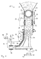
- Fig. 1 shows a device generally designated 10 for mixing a Solid with a liquid.
- the device comprises a storage container 12 with a solids bed 13, which via a pulse conveying device 14 in a Solid feed space 16 is introduced.
- the pulse conveying device 14 has a first ball valve 18, which via a chain drive 20 is synchronized with a second ball valve 22 and of a drive motor 24 is driven. Between the first and the second Ball valve 18, 22 is an intermediate chamber 26.
- the intermediate chamber 26th charged with the solids bed 13 contained in the reservoir 12, while the second ball valve 22 the solids supply chamber 16 against the ambient atmosphere seals.
- the second ball valve 22 so that in the intermediate chamber 26th befindliches solids bed 13 is discharged into the solids supply chamber 16.
- the first ball valve 18 is then in its closed position.
- a Pressure measuring device 28 for detecting the pressure in the solids feed space 16 and a control device 30 is present, the power of the drive motor 24 in Dependence of the pressure detected by the pressure measuring device 28 regulates pressure.
- the control device 30 controls the Power of the drive motor 24 such that the metering speed of the impulse conveying device 14 is reduced.
- the control device 30 via a connecting line, not shown in the figure with the pump 38th be connected and the dosing speed of the acceleration space 42 supplied liquid 32 as a function of the pressure measuring device 28th control detected pressure in the solids supply chamber 16.
- a liquid 32 to be mixed with the solids bed 13 is located in a container 34 into which via a metering line 36 one or more liquid components be initiated. Downstream of the container 34 is in a Supply line 37, a pump 38 is arranged, the liquid 32 from the container 34 promotes under pressure to an inlet nozzle 40.
- the liquid 32 flows out of the inlet nozzle 40 an acceleration space 42.
- the inlet nozzle 40 is tangent to a housing wall 44 and thus tangential to the flow direction of the liquid 32 in Acceleration space 42 arranged and inclined in the flow direction.
- the acceleration space 42 has an annular cross-section and is of the housing 44 and of an axially movable partition 46th limited, which separates the acceleration space 42 from the solids feed space 16.
- a Bescheun Trentsraum 42 facing surface 48 of the partition 46th and a surface 50 of the housing wall facing the acceleration space 42 44 are spiral and inclined in the direction of flow recesses 52 present, each flow channels for in a rotary motion form offset fluid 32.
- a rotor 54 has a first, a second and third rotor sections 56, 58, 60, wherein the first rotor section 56 of the pulse conveying device 14 facing and in the solid feed space 16 is arranged. Further, the first rotor portion 56 is provided with a Pre-treatment head 62 provided. The second rotor section 58 is also in Solid feed space 16 is arranged and has several perpendicular to the rotor axis A extending atomizer 64 on. At the frustoconical latestbifdeten third rotor section 60, a plurality of conveyor webs 66 are attached, which are provided in part with holes 68. As shown in Fig. 1, the Rotor 54 driven by a rotor drive motor 70. The axial displacement of the Rotor 54 is connected by means of a piston 72 connected to a hydraulic pump 74 realized.
- the compressor chamber 78 Downstream of the acceleration chamber 42 are a mixing chamber 76 and a compressor chamber 78.
- the compressor chamber 78 has an annular gap-shaped cross-section and is of a frustoconical portion 80 of Housing 44 and the frustoconical third rotor section 60 limited.
- the liquid 32 in the acceleration space 42 By introducing the pressurized liquid 32 through the tangential to the Housing 44 arranged and inclined in the flow direction inlet nozzle 40, the liquid 32 in the acceleration space 42 in a rotational movement offset and accelerated to a predetermined speed.
- the of the Pulse conveying device 14 supplied solids 13 are in the solid feed space 16 of the rotor 54 also in a rotational movement, wherein in the solids 13 existing powder agglomerates first from the pretreatment head 62 coarsely crushed and then from the Zerstäubungsmessem 64 fine be atomized.
- a flow velocity measuring device not shown in the drawing the velocity of the liquid 32 in the Acceleration space 42 detected.
- a likewise not shown control device controls the rotational speed of the rotor 54 so that it is the speed
- the liquid 32 in the acceleration space 42 corresponds
- the Liquid 32 in the acceleration space 42 and the solids 13 in the solids feed space 16 in mutually synchronous rotational movements, so that in Mixing chamber 76 creates a laminar flow.
- the liquid 32 flows with a constant Rotary speed in the mixing chamber 76, where it with the solid particles 13 is mixed, wherein the solid particles 13 in the form of finely atomized agglomerates, but not present as primary particles.
- the powder particles 13 are through the as a result of the rotational movement centrifugal forces in the direction of along the housing wall 44 flowing liquid layer transported.
- the Surface resistance of the housing 44 arise deep-seated in the Liquid layer through which also directly along the housing 44th flowing liquid layers in the direction of the solid feed space 16th facing surface of the liquid flow are transported to where they Mixture with the supplied solid particles 13 are available.
- the solid / liquid suspension flows into the compressor chamber 78, where they by means of the frustoconical third rotor section 60 is accelerated. Due to the increased flow velocity of the Suspension in the compressor chamber 78 arises in an inlet region 82 of the compressor chamber 78 decreased as a result of the increase in the flow rate static pressure a suction effect (jet pump effect), so that in the Capillaries of the fine powder agglomerates 13 is sucked in air. Because the Impulse conveying device 14 also the solid feed chamber 16 against the Seals ambient atmosphere, creates a negative pressure in the solids supply chamber 16, so that the supplied solid particles 13 already in the solid feed space 16 be vented.
- the suspension flows out of the compressor chamber 78 in a first outlet line 84.
- a pressure regulator 86 is present.
- the Suspension are emptied into a second outlet line 88, in which another Pressure regulator 90 to maintain a constant pressure is present. It However, it is also possible to direct the suspension in the container 34 and from there in the cycle in the acceleration space 42 due.
- Fig. 3 is a detail of an alternative embodiment of the mixing device 10, in which rotor 54 has a fourth rotor section 92.
- the fourth Rotor section 92 consists of a parallel to the rotor axis A extending first section 94 and at an angle of about 60 ° to the rotor axis A extending second portion 96.
- the first portion 94 forms a mixing chamber 76 completely and the acceleration space 42 at least partially limiting, rotatable outer wall, by means of which the rotational speed of the liquid 32nd maintained in the acceleration space 42 and / or the suspension in the mixing chamber 76 can be.
- the second section 96 provided with a suspension passage opening 98.
- the partition 46 and a parallel to the housing 44 arranged Wall 100 with a perpendicular to the rotor axis A extending fifth Rotor section 102 connected.
- the wall 100 extends along the acceleration space 42 and along a substantial portion of the mixing space 76.
- an axial displacement of Partition 46 not possible.
- the fifth rotor section 102 is provided with a solids passage opening 104, while the wall 100 a liquid inlet opening 106 for the unhindered Inlet of the liquid 32 in the acceleration space 42 has.
- the rotatable arrangement of the wall 100 and the partition 46 may be the liquid 32 particularly accelerated in the acceleration space 42 and the rotational speed the suspension in the mixing chamber 76 are maintained, so that the Mixing device 10, in particular for processing highly viscous or pseudoplastic Liquids and suspensions is suitable.
- the embodiment of the mixing device 10 shown in FIG. 5 has a rotatable portion 108 of the housing 44, which each have subregions the acceleration space 42 and the mixing chamber 46 extends. Also at In this embodiment, an axial displacement of the partition wall 46 is not possible.
- the drive of the rotatable portion 108 of the housing 44 can with be coupled to the rotor drive 70. However, it is also possible one of the Rotor drive 70 separate drive for the rotatable portion 108 of the housing 44 to provide.
- the embodiment of the mixing device 10 shown in FIG. 6 has a Solid feed chamber 16 and a hopper 110 with a funnel-shaped Inlet opening.
- the hopper 110 is seated in a lid 112 of a housing 114 of the mixing device 10 and is screwed to this.
- a radially arranged material outlet 118 is provided via which flows out of the mixing material generated in the compressor chamber 78.
- the rotor 54 of the mixing device 10 differs from that in FIGS. 1 to 5 shown rotors in that it is not provided with a pretreatment head first rotor section and not equipped with sputtering second Rotor section includes. Instead, the rotor 54 is frustoconical in shape, so that the annular gap-shaped compressor chamber 78 from an inner wall 120 of the Cover 112 and a frusto-conical surface of a central portion 122 of the rotor 54 is limited.
- the inner wall 120 of the lid 112 and the frusto-conical Surface of the rotor 54 extend under in the portion 122 under an angle of 5 °, so that the compressor chamber 78 forming annular gap from the inlet region 82 of the compressor chamber in the direction of the material outlet 118 rejuvenated.
- the distance of the conveyor 66, which remains in the area of Compressor space 78 are designed as webs, with respect to the inner wall 120 of the Lids 112 constant.
- the rotor 54 has the largest Diameter up. The sections arranged in the outlet region 128 of the rotor 54 the conveyors 66 thus generate a relation to the mixing chamber 76th higher centrifugal flow and support a residue-free discharge.
- the rotor 54 projects into the solid feed space 16 into the lower end of the hopper 110.
- the conveyor webs 66 extend until close to a wall 136 of the hopper 110. If the via a shaft 126 rotatably connected to a drive rotor 54, prevent in the direction of Rotor axis A to the material outlet 118 promotional conveyor webs 66 the penetration of Liquid in the interior of the hopper 110. To improve the catchment effect are the conveyor webs 66 on which the solid feed space 16 facing End of the rotor 54 inclined by about 45 ° in the direction of rotation.
- inlet nozzles 40 Similar to the embodiments shown in FIGS Liquid supply through inlet nozzles 40, which in an attachment 134 of the lid 112 are attached.
- the inlet nozzles 40 are facing the compressor chamber 78 End of the wall 136 of the hopper 110 opposite.
- the liquid supply can be via one or a plurality of inlet nozzles 40 distributed around the cap 134 take place, wherein, if required, also various liquid additives can be introduced.
- FIGS. 7 and 8 in the mixing device according to the Fig. 6 used rotor 54 illustrates the arrangement of the web-shaped conveyors 66.
- the rotor 54 shown here are in Distance of 45 ° eight conveyor webs 66 distributed over the surface of the rotor 54.
- the Inclination of the conveyor webs 66 relative to the rotor axis A is in individual areas of action of the rotor 54 different.
- the conveyor webs 66 are inclined by 45 ° in the direction of rotation and have their greatest height.
- the mixing chamber 76 in which the liquid with the dry material is mixed, the conveyor webs 66 extend along the rotor axis A.
- the conveyor webs 66 are inclined by 30 ° to the rotor axis. in the Outlet region 128 of the rotor 54 extend the conveyor webs 66 axially parallel to Rotor axis A along the entire outer semicircular cross section of Rotor 54.
Landscapes
- Chemical & Material Sciences (AREA)
- Chemical Kinetics & Catalysis (AREA)
- Dispersion Chemistry (AREA)
- Mixers Of The Rotary Stirring Type (AREA)
Abstract
Description
- Fig. 1
- eine schematische Darstellung eines ersten Ausführungsbeispiels der erfindungsgemäßen Mischvorrichtung;
- Fig. 2
- einen Ausschnitt des in Fig. 1 gezeigten ersten Ausführungsbeispiels der erfindungsgemäßen Mischvorrichtung;
- Fig. 3
- einen Ausschnitt eines zweiten Ausführungsbeispiels der erfindungsgemäßen Mischvorrichtung;
- Fig. 4
- einen Ausschnitt eines dritten Ausführungsbeispiels der erfindungsgemäßen Mischvorrichtung;
- Fig. 5
- einen Ausschitt eines vierten Ausführungsbeispiels der erfindungsgemäßen Mischvorrichtung;
- Fig. 6
- einen Ausschitt eines fünften Ausführungsbeispiels der erfindungsgemäßen Mischvorrichtung;
- Fig. 7
- eine Querschnittsansicht des Rotors der in der Fig. 6 gezeigten Mischvorrichtung; und
- Fig. 8
- eine Draufsicht auf den in der Fig. 7 dargestellten Rotor.
Claims (19)
- Vorrichtung (10) zum Vermischen eines pulverförmigen oder körnigen Feststoffs (13) mit einer Flüssigkeit (32), mit:mindestens einer Feststoff-Zufuhreinrichtung (14),mindestens einer Flüssigkeits-Zufuhreinrichtung (37, 38,-40),einem Beschleunigungsraum (42), in dem die zugeführte Flüssigkeit (32) in eine Drehbewegung versetzt und auf eine vorbestimmte Geschwindigkeit beschleunigt wird,einem Feststoff-Zufuhrraum (16), in dem die zugeführten Feststoffteilchen (13) in eine Drehbewegung versetzt werden,einem Mischraum (76) zum Vermischen der Feststoffteilchen (13) mit der Flüssigkeit (32) zu einer Suspension unter Aufrechterhaltung der zuvor erzeugten Drehbewegung undeinem Verdichterraum (78), in dem die sich drehende Suspension derart beschleunigt wird, dass in einem Eintrittsbereich (82) des Verdichterraums (78) eine Saugwirkung entsteht, die die zugeführte Feststoffschüttung (13) zumindest im wesentlichen entlüftet.
- Vorrichtung nach Anspruch 1,
dadurch gekennzeichnet, dass die Feststoff-Zufuhreinrichtung (14) eine Impulsförderungseinrichtung zum Zuführen des Feststoffs (13) und Abdichten des Feststoff-Zufuhrraums (16) von der Umgebungsatmosphäre umfasst. - Vorrichtung nach Anspruch 1 oder 2,
dadurch gekennzeichnet, dass die Flüssigkeits-Zufuhreinrichtung (37, 38, 40) mindestens eine Einlassdüse (40), die tangential zur Strömungsrichtung der Flüssigkeit (32) im Beschleunigungsraum (42) angeordnet und in Strömungsrichtung geneigt ist, sowie eine Vorrichtung (38) zum unter Druck setzen der zuzuführenden Flüssigkeit (32) umfasst. - Vorrichtung nach einem der vorangehenden Ansprüche,
dadurch gekennzeichnet, dass der Beschleunigungsraum (42) einen im wesentlichen kreisringförmigen Querschnitt aufweist und durch eine Trennwand (46) von dem Feststoff-Zufuhrraum (16) getrennt ist. - Vorrichtung nach Anspruch 4,
dadurch gekennzeichnet, dass an einer dem Beschleunigungsraum (42) zugewandten Fläche (48) der Trennwand (46) und/oder einer dem Beschleunigungsraum (42) zugewandten Fläche (50) einer den Beschleunigungsraum (42) zumindest teilweise begrenzenden äußeren Wandung (44; 92; 100) spiralförmig verlaufende und in Strömungsrichtung geneigte Strömungskanäle (52) ausgebildet sind. - Vorrichtung nach Anspruch 4 oder 5,
dadurch gekennzeichnet, dass die Trennwand (46) und/oder die den Beschleunigungsraum (42) zumindest teilweise begrenzende äußere Wandung (92; 100; 108) und/oder eine den Mischraum (76) zumindest teilweise begrenzende äußere Wandung (92; 100; 108) drehbar sind. - Vorrichtung nach einem der Ansprüche 4 bis 6,
dadurch gekennzeichnet, dass die Trennwand (46) axial verschiebbar ist. - Vorrichtung nach einem der vorangehenden Ansprüche,
dadurch gekennzeichnet, dass ein Rotor (54) mit einem ersten, einem zweiten und einem dritten Rotorabschnitt (56, 58, 60) vorhanden ist, wobei der erste Rotorabschnitt (56) ein der Feststoff-Zufuhreinrichtung (14) zugewandter, im Feststoff-Zufuhrraum (16) angeordneter und mit einem Vorbehandlungskopf (62) versehener Abschnitt des Rotors (54) ist. - Vorrichtung nach den Ansprüchen 6 und 8,
dadurch gekennzeichnet, dass die drehbare Trennwand (46) und/oder die den Beschleunigungsraum (42) zumindest teilweise begrenzende äußere Wandung (92; 100) und/oder die den Mischraum zumindest teilweise begrenzende äußere Wandung (92; 100) mit dem Rotor (54) verbunden ist/sind. - Vorrichtung nach Anspruch 8 oder 9,
dadurch gekennzeichnet, dass sich der zweite Rotorabschnitt (58) zumindest teilweise in den Feststoff-Zufuhrraum (16) erstreckt und mit Zerstäubungsmessem (64) versehen ist. - Vorrichtung nach einem der Ansprüche 8 bis 10,
dadurch gekennzeichnet, dass der Verdichterraum (78) einen ringspaltförmigen Querschnitt aufweist und von einem kegelstumpfförmig ausgebildeten Abschnitt (80) einer äußeren Wandung (44) und dem zumindest im Bereich des Verdichterraums (78) kegelstumpfförmig ausgebildeten dritten Rotorabschnitt (60) begrenzt wird. - Vorrichtung nach einem der Ansprüche 8 bis 11,
dadurch gekennzeichnet, dass sie eine erste Erfassungseinrichtung zur Erfassung der Strömungsgeschwindigkeit der Flüssigkeit (32) im Beschleunigungsraum (42) und/oder eine zweite Erfassungseinrichtung zur Erfassung der Strömungsgeschwindigkeit der Suspension im Verdichterraum (78) und eine erste Regeleinrichtung zum Regeln der Drehgeschwindigkeit des Rotors (54) in Abhängigkeit der erfassten Strömungsgeschwindigkeiten) umfasst. - Vorrichtung nach Anspruch 12,
dadurch gekennzeichnet, dass die erste Regeleinrichtung die Drehgeschwindigkeit des Rotors (54) so regelt, dass sie der Strömungsgeschwindigkeit der Flüssigkeit (32) im Beschleunigungsraum (42) entspricht. - Vorrichtung nach einem der Ansprüche 8 bis 13,
dadurch gekennzeichnet, dass an dem dritten Rotorabschnitt (60) stegförmige, mit Bohrungen (68) versehene Fördereinrichtungen (66) angeordnet sind. - Vorrichtung nach einem der Ansprüche 8 bis 14,
dadurch gekennzeichnet, dass der Rotor (54) axial verschiebbar ist. - Vorrichtung nach einem der vorangehenden Ansprüche,
dadurch gekennzeichnet, dass sie eine dritte Erfassungseinrichtung (28) zur Erfassung des im Feststoff-Zufuhrraum (16) vorherschenden Drucks und eine zweite Regeleinrichtung (30) zum Regeln der Dosiergeschwindigkeit(en) der Feststoff-Zufuhr-einrichtung (14) und/oder der Flüssigkeits-Zuführeinrichtung (37, 38, 40) umfasst. - Verfahren zum Vermischen eines pulverförmigen oder körnigen Feststoffs (13) mit einer Flüssigkeit (32) mit den Schritten:Zuführen des Feststoffs (13),Zuführen der Flüssigkeit (32),Erzeugen einer Drehbewegung der zugeführten Flüssigkeit (32) und Beschleunigen der Flüssigkeit (32) auf eine vorbestimmte Geschwindigkeit in einem Beschleunigungsraum (42),Erzeugen einer Drehbewegung der zugeführten Feststoffteilchen (13) in einem Feststoff-Zufuhrraum (16),Vermischen der Feststoffteilchen (13) mit der Flüssigkeit (32) zu einer Suspension unter Aufrechterhaltung der zuvor erzeugten Drehbewegung in einem Mischraum (76) undBeschleunigen der sich drehenden Suspension in einem Verdichterraum (78) derart, dass in einem Eintrittsbereich (82) des Verdichterraum (78) eine Saugwirkung entsteht, die die zugeführte Feststoffschüttung (13) zumindest im wesentlichen entlüftet.
- Verfahren nach Anspruch 17,
dadurch gekennzeichnet, dass im Mischraum (76) die Flüssigkeitsoberflächenströmung im wesentlichen gleich der spezifischen Teilchenoberfläche der in den Mischraum (76) eingebrachten Feststoffteilchen (13) ist. - Verfahren nach Anspruch 17 oder 18,
dadurch gekennzeichnet, dass im Mischraum (76) eine vertikale Fließgeschwindigkeit der Suspension mindestens 1-2 m/s beträgt.
Applications Claiming Priority (5)
| Application Number | Priority Date | Filing Date | Title |
|---|---|---|---|
| DE10139413 | 2001-08-17 | ||
| DE10139413A DE10139413B4 (de) | 2001-08-17 | 2001-08-17 | Vorrichtung zum Mischen und Dispergieren von pulverförmigen feinst- bis grobkörnigen Substanzen mit mindestens einer Flüssigkeit |
| DE10163397A DE10163397B4 (de) | 2001-12-21 | 2001-12-21 | Vorrichtung und Verfahren zum Vermischen eines Feststoffs mit einer Flüssigkeit |
| DE10163397 | 2001-12-21 | ||
| PCT/EP2002/009265 WO2003022416A1 (de) | 2001-08-17 | 2002-08-19 | Vorrichtung und verfahren zum vermischen eines feststoffs mit einer flüssigkeit |
Publications (2)
| Publication Number | Publication Date |
|---|---|
| EP1423185A1 EP1423185A1 (de) | 2004-06-02 |
| EP1423185B1 true EP1423185B1 (de) | 2005-01-19 |
Family
ID=26009927
Family Applications (1)
| Application Number | Title | Priority Date | Filing Date |
|---|---|---|---|
| EP02764856A Expired - Lifetime EP1423185B1 (de) | 2001-08-17 | 2002-08-19 | Vorrichtung und verfahren zum vermischen eines feststoffs mit einer flüssigkeit |
Country Status (6)
| Country | Link |
|---|---|
| US (1) | US7287897B2 (de) |
| EP (1) | EP1423185B1 (de) |
| CN (1) | CN1240471C (de) |
| DE (1) | DE50202072D1 (de) |
| ES (1) | ES2233860T3 (de) |
| WO (1) | WO2003022416A1 (de) |
Families Citing this family (20)
| Publication number | Priority date | Publication date | Assignee | Title |
|---|---|---|---|---|
| DE10320739B3 (de) * | 2003-05-09 | 2004-10-21 | Ika - Werke Gmbh & Co. Kg | Vorrichtung zum Dispergieren und/oder Homogenisieren |
| DE102006012489A1 (de) * | 2006-03-16 | 2007-09-20 | Netzsch-Feinmahltechnik Gmbh | Verfahren und Vorrichtung zur Erzaufbereitung |
| US8372348B2 (en) * | 2008-06-30 | 2013-02-12 | Arch Chemicals, Inc. | Apparatus and method for mixing a concentrated water treatment solution |
| CN101879420B (zh) * | 2010-05-18 | 2012-05-23 | 云南大红山管道有限公司 | 一种固体粉末的制浆系统 |
| US8580103B2 (en) | 2010-11-22 | 2013-11-12 | Metcon, Llc | Electrolyte solution and electrochemical surface modification methods |
| US8715720B2 (en) * | 2011-09-14 | 2014-05-06 | Scott Murray | Cloud mixer and method of minimizing agglomeration of particulates |
| CN102614792B (zh) * | 2012-03-31 | 2013-12-18 | 和原生态控股股份有限公司 | 一种智能配肥机 |
| DE102016102728A1 (de) * | 2015-08-13 | 2017-02-16 | Netzsch-Feinmahltechnik Gmbh | Vorrichtung und Verfahren zum Dispergieren mindestens einer Substanz in einem Fluid |
| CN108465388B (zh) * | 2017-07-25 | 2025-01-10 | 深圳市尚水智能股份有限公司 | 一种固液混合设备及利用该设备的混合方法 |
| CN109772189B (zh) * | 2017-11-13 | 2024-12-27 | 深圳市尚水智能股份有限公司 | 适合高粘度物料的固液混合设备及利用该设备的混合方法 |
| CN108671789A (zh) * | 2018-02-27 | 2018-10-19 | 罗斯(无锡)设备有限公司 | 一种粉料与液体预混机 |
| CN108404749A (zh) * | 2018-04-26 | 2018-08-17 | 无锡先导智能装备股份有限公司 | 液体加料机构及制浆装置 |
| CN108393008A (zh) * | 2018-04-26 | 2018-08-14 | 无锡先导智能装备股份有限公司 | 搅拌机构及制浆装置 |
| CN109173815A (zh) * | 2018-10-10 | 2019-01-11 | 深圳市尚水智能设备有限公司 | 一种用于固体和液体混合的设备及其方法 |
| CN110394082B (zh) * | 2019-07-31 | 2021-08-13 | 深圳市尚水智能设备有限公司 | 一种叶轮组件及使用该组件的固体和液体混合设备 |
| CN111407984B (zh) * | 2020-04-13 | 2022-03-25 | 李青翠 | 一种便捷式呼吸内科给药设备 |
| CN115869794B (zh) * | 2021-09-23 | 2024-06-25 | 深圳市尚水智能股份有限公司 | 一种用于固液混合及分散的装置及设备 |
| US12350632B2 (en) | 2021-10-13 | 2025-07-08 | Shangshui Smartech Ltd. | Impeller assembly and mixing apparatus |
| DE102022101814B4 (de) * | 2022-01-26 | 2025-12-18 | Ekato Systems Gmbh | Vorrichtung, System und Verfahren zum Homogenisieren und/oder Dispergieren fließfähiger Stoffe |
| CN218307353U (zh) * | 2022-08-16 | 2023-01-17 | 宏工科技股份有限公司 | 一种制浆机 |
Family Cites Families (17)
| Publication number | Priority date | Publication date | Assignee | Title |
|---|---|---|---|---|
| DE41822C (de) | DlERKS & MÖLLMANN in Osnabrück | Neuerung an Futterschneidemaschinen | ||
| DE436368C (de) | 1925-03-28 | 1926-10-30 | Sudenburger Maschinenfabrik & | Vorrichtung zur Herstellung von kolloiden Stoffen auf mechanischem Wege |
| US1851071A (en) | 1928-06-30 | 1932-03-29 | Travis Pierce Mason | Dispersion mill |
| NL200327A (de) | 1952-11-25 | |||
| DE1272894B (de) * | 1963-12-23 | 1968-07-18 | Pierre Alexandre Foucault | Vorrichtung zum Mischen eines pulverfoermigen Stoffes mit einer Fluessigkeit |
| FR2036249A5 (de) | 1969-03-07 | 1970-12-24 | Neyrpic Bmb | |
| US3606270A (en) | 1970-05-14 | 1971-09-20 | Ludish Co | Continuous power blender |
| DE2403053A1 (de) * | 1974-01-23 | 1975-07-31 | Supraton Auer & Zucker | Einrichtung zur herstellung einer suspension aus hochquellfaehigen stoffen |
| US4106117A (en) * | 1976-05-07 | 1978-08-08 | Waukesha Foundry Company, Inc. | Apparatus for mixing particulate material in a liquid |
| US4239396A (en) | 1979-01-25 | 1980-12-16 | Condor Engineering & Manufacturing, Inc. | Method and apparatus for blending liquids and solids |
| DD262813A1 (de) | 1987-08-12 | 1988-12-14 | Sket Veb Ingenieurbetrieb Fuer | Verfahren und vorrichtung zur fest-fluessig mischung |
| GB8902883D0 (en) | 1989-02-09 | 1989-03-30 | North West Water Authority | Improvements in or relating to mixing devices |
| JP3591874B2 (ja) * | 1994-06-21 | 2004-11-24 | 東レ・ダウコーニング・シリコーン株式会社 | 液体と粉体の連続混練装置 |
| DE19629945C5 (de) * | 1996-07-25 | 2008-10-16 | Ika-Werke Gmbh & Co. Kg | Mischvorrichtung zum Vermischen von pulverförmigen und/oder körnigen Partikeln mit einer Flüssigkeit |
| US5932270A (en) * | 1997-07-09 | 1999-08-03 | The J. M. Smucker Company | Cold process, oven stable fruit paste and method of making such paste |
| US5904419A (en) | 1997-07-29 | 1999-05-18 | Arribau; Jorge O. | Blender method and apparatus |
| DE10139413B4 (de) | 2001-08-17 | 2004-02-05 | Netzsch-Feinmahltechnik Gmbh | Vorrichtung zum Mischen und Dispergieren von pulverförmigen feinst- bis grobkörnigen Substanzen mit mindestens einer Flüssigkeit |
-
2002
- 2002-08-19 WO PCT/EP2002/009265 patent/WO2003022416A1/de not_active Ceased
- 2002-08-19 EP EP02764856A patent/EP1423185B1/de not_active Expired - Lifetime
- 2002-08-19 ES ES02764856T patent/ES2233860T3/es not_active Expired - Lifetime
- 2002-08-19 CN CNB028160851A patent/CN1240471C/zh not_active Expired - Lifetime
- 2002-08-19 DE DE50202072T patent/DE50202072D1/de not_active Expired - Lifetime
-
2006
- 2006-08-04 US US11/499,455 patent/US7287897B2/en not_active Expired - Lifetime
Also Published As
| Publication number | Publication date |
|---|---|
| ES2233860T3 (es) | 2005-06-16 |
| US7287897B2 (en) | 2007-10-30 |
| CN1543376A (zh) | 2004-11-03 |
| CN1240471C (zh) | 2006-02-08 |
| DE50202072D1 (de) | 2005-02-24 |
| EP1423185A1 (de) | 2004-06-02 |
| US20060268657A1 (en) | 2006-11-30 |
| WO2003022416A1 (de) | 2003-03-20 |
Similar Documents
| Publication | Publication Date | Title |
|---|---|---|
| EP1423185A1 (de) | Vorrichtung und verfahren zum vermischen eines feststoffs mit einer flüssigkeit | |
| DE3630536C2 (de) | ||
| DE10351962B4 (de) | Homogenisierapparat | |
| DE69501365T2 (de) | Vorrichtung zum kontinuierlichen Mischen von Flüssigkeit und Pulver | |
| DE2823604A1 (de) | Strahlmischersystem mit ejektorduese | |
| DE2135332A1 (de) | Vorrichtung zur homogenen Feinverteilung eines Strömungsmittels durch ein anderes | |
| EP0346278A1 (de) | Vorrichtung zum Benetzen von Saatgut | |
| WO2003066203A1 (de) | Dispergier-vorrichtung | |
| DE69115308T2 (de) | Verfahren und Vorrichtung zum Mischen von Festkörpern und Flüssigkeiten | |
| EP0046569A2 (de) | Verfahren und Vorrichtung zum Mischen von Feststoffen mit Flüssigkeiten | |
| DE1963376A1 (de) | Einrichtung zum Zugeben und Verteilen einer Fluessigkeit bzw. eines Gases in anderen Medien | |
| EP0638365B2 (de) | Verfahren und Vorrichtung zur Trennung eines feinkörnigen Feststoffes in zwei Kornfraktionen | |
| DE10139413B4 (de) | Vorrichtung zum Mischen und Dispergieren von pulverförmigen feinst- bis grobkörnigen Substanzen mit mindestens einer Flüssigkeit | |
| DE2061460C3 (de) | Vorrichtung zum Dispergieren von Teilchenmaterial | |
| DE1531019A1 (de) | Geraet zum dosierten Transportieren von pulverfoermigen Material | |
| EP1186348B1 (de) | Verfahren und Vorrichtung zum Zerstäuben von Flüssigkeiten | |
| DE1118959B (de) | Verfahren und Vorrichtung zur Aufbereitung von Thermoplasten oder Duroplasten | |
| EP0359113B1 (de) | Vorrichtung zum kontinuierlichen Fördern von Pulver in einen Gasstrom | |
| DE2740789C2 (de) | Vorrichtung zum kontinuierlichen mechanischen Vermischen von zwei Komponenten | |
| EP3914379B1 (de) | Mischvorrichtung | |
| EP3334519B1 (de) | Vorrichtung und verfahren zum dispergieren mindestens einer substanz in einem fluid | |
| DE3216648A1 (de) | Decken-stuetzbalken-vergusssystem | |
| DE3418634A1 (de) | Vorrichtung zum dispergieren von pulver | |
| DE10163397B4 (de) | Vorrichtung und Verfahren zum Vermischen eines Feststoffs mit einer Flüssigkeit | |
| DE10329813B4 (de) | Vorrichtung zur Ausbildung von Umhüllungen auf Oberflächen fester Körper in einer Beschichtungskammer |
Legal Events
| Date | Code | Title | Description |
|---|---|---|---|
| PUAI | Public reference made under article 153(3) epc to a published international application that has entered the european phase |
Free format text: ORIGINAL CODE: 0009012 |
|
| 17P | Request for examination filed |
Effective date: 20040210 |
|
| AK | Designated contracting states |
Kind code of ref document: A1 Designated state(s): AT BE BG CH CY CZ DE DK EE ES FI FR GB GR IE IT LI LU MC NL PT SE SK TR |
|
| AX | Request for extension of the european patent |
Extension state: AL LT LV MK RO SI |
|
| GRAP | Despatch of communication of intention to grant a patent |
Free format text: ORIGINAL CODE: EPIDOSNIGR1 |
|
| RBV | Designated contracting states (corrected) |
Designated state(s): CH DE ES GB IT LI |
|
| GRAS | Grant fee paid |
Free format text: ORIGINAL CODE: EPIDOSNIGR3 |
|
| RIN1 | Information on inventor provided before grant (corrected) |
Inventor name: SCHERTENLEIB, PETER |
|
| GRAA | (expected) grant |
Free format text: ORIGINAL CODE: 0009210 |
|
| AK | Designated contracting states |
Kind code of ref document: B1 Designated state(s): CH DE ES GB IT LI |
|
| REG | Reference to a national code |
Ref country code: GB Ref legal event code: FG4D Free format text: NOT ENGLISH |
|
| REG | Reference to a national code |
Ref country code: CH Ref legal event code: EP |
|
| REF | Corresponds to: |
Ref document number: 50202072 Country of ref document: DE Date of ref document: 20050224 Kind code of ref document: P |
|
| REG | Reference to a national code |
Ref country code: CH Ref legal event code: NV Representative=s name: PATENTANWAELTE SCHAAD, BALASS, MENZL & PARTNER AG |
|
| GBT | Gb: translation of ep patent filed (gb section 77(6)(a)/1977) |
Effective date: 20050418 |
|
| REG | Reference to a national code |
Ref country code: ES Ref legal event code: FG2A Ref document number: 2233860 Country of ref document: ES Kind code of ref document: T3 |
|
| PLBE | No opposition filed within time limit |
Free format text: ORIGINAL CODE: 0009261 |
|
| STAA | Information on the status of an ep patent application or granted ep patent |
Free format text: STATUS: NO OPPOSITION FILED WITHIN TIME LIMIT |
|
| 26N | No opposition filed |
Effective date: 20051020 |
|
| PGFP | Annual fee paid to national office [announced via postgrant information from national office to epo] |
Ref country code: DE Payment date: 20200825 Year of fee payment: 19 Ref country code: ES Payment date: 20200902 Year of fee payment: 19 Ref country code: GB Payment date: 20200826 Year of fee payment: 19 |
|
| PGFP | Annual fee paid to national office [announced via postgrant information from national office to epo] |
Ref country code: CH Payment date: 20200826 Year of fee payment: 19 Ref country code: IT Payment date: 20200831 Year of fee payment: 19 |
|
| REG | Reference to a national code |
Ref country code: DE Ref legal event code: R079 Ref document number: 50202072 Country of ref document: DE Free format text: PREVIOUS MAIN CLASS: B01F0013100000 Ipc: B01F0033800000 |
|
| REG | Reference to a national code |
Ref country code: DE Ref legal event code: R119 Ref document number: 50202072 Country of ref document: DE |
|
| REG | Reference to a national code |
Ref country code: CH Ref legal event code: PL |
|
| GBPC | Gb: european patent ceased through non-payment of renewal fee |
Effective date: 20210819 |
|
| PG25 | Lapsed in a contracting state [announced via postgrant information from national office to epo] |
Ref country code: LI Free format text: LAPSE BECAUSE OF NON-PAYMENT OF DUE FEES Effective date: 20210831 Ref country code: CH Free format text: LAPSE BECAUSE OF NON-PAYMENT OF DUE FEES Effective date: 20210831 |
|
| PG25 | Lapsed in a contracting state [announced via postgrant information from national office to epo] |
Ref country code: IT Free format text: LAPSE BECAUSE OF NON-PAYMENT OF DUE FEES Effective date: 20210819 Ref country code: GB Free format text: LAPSE BECAUSE OF NON-PAYMENT OF DUE FEES Effective date: 20210819 Ref country code: DE Free format text: LAPSE BECAUSE OF NON-PAYMENT OF DUE FEES Effective date: 20220301 |
|
| REG | Reference to a national code |
Ref country code: ES Ref legal event code: FD2A Effective date: 20220929 |
|
| PG25 | Lapsed in a contracting state [announced via postgrant information from national office to epo] |
Ref country code: ES Free format text: LAPSE BECAUSE OF NON-PAYMENT OF DUE FEES Effective date: 20210820 |