EP1422663B1 - Method and apparatus for determining the distance of visibility of the driver of a vehicle - Google Patents
Method and apparatus for determining the distance of visibility of the driver of a vehicle Download PDFInfo
- Publication number
- EP1422663B1 EP1422663B1 EP03292599.2A EP03292599A EP1422663B1 EP 1422663 B1 EP1422663 B1 EP 1422663B1 EP 03292599 A EP03292599 A EP 03292599A EP 1422663 B1 EP1422663 B1 EP 1422663B1
- Authority
- EP
- European Patent Office
- Prior art keywords
- vehicle
- image
- gravity
- determining
- zones
- Prior art date
- Legal status (The legal status is an assumption and is not a legal conclusion. Google has not performed a legal analysis and makes no representation as to the accuracy of the status listed.)
- Expired - Lifetime
Links
- 238000000034 method Methods 0.000 title claims description 40
- 230000005484 gravity Effects 0.000 claims description 23
- 238000001514 detection method Methods 0.000 claims description 7
- 230000011218 segmentation Effects 0.000 claims description 5
- 238000004364 calculation method Methods 0.000 claims description 4
- 239000000779 smoke Substances 0.000 claims description 4
- 239000003595 mist Substances 0.000 claims description 2
- 230000004927 fusion Effects 0.000 claims 1
- 238000000926 separation method Methods 0.000 claims 1
- 238000005259 measurement Methods 0.000 description 9
- 230000006870 function Effects 0.000 description 8
- 230000005540 biological transmission Effects 0.000 description 2
- 230000001276 controlling effect Effects 0.000 description 2
- 230000004297 night vision Effects 0.000 description 2
- 230000001105 regulatory effect Effects 0.000 description 2
- XLYOFNOQVPJJNP-UHFFFAOYSA-N water Substances O XLYOFNOQVPJJNP-UHFFFAOYSA-N 0.000 description 2
- 241001080024 Telles Species 0.000 description 1
- 238000004458 analytical method Methods 0.000 description 1
- 230000008033 biological extinction Effects 0.000 description 1
- 238000009792 diffusion process Methods 0.000 description 1
- 230000006872 improvement Effects 0.000 description 1
- 230000010354 integration Effects 0.000 description 1
- 230000003993 interaction Effects 0.000 description 1
- 230000003287 optical effect Effects 0.000 description 1
- 230000003071 parasitic effect Effects 0.000 description 1
- 239000002245 particle Substances 0.000 description 1
- 238000005375 photometry Methods 0.000 description 1
- 230000008569 process Effects 0.000 description 1
- 230000035945 sensitivity Effects 0.000 description 1
- 230000011664 signaling Effects 0.000 description 1
- 230000009131 signaling function Effects 0.000 description 1
- 239000000725 suspension Substances 0.000 description 1
Images


Classifications
-
- B—PERFORMING OPERATIONS; TRANSPORTING
- B60—VEHICLES IN GENERAL
- B60Q—ARRANGEMENT OF SIGNALLING OR LIGHTING DEVICES, THE MOUNTING OR SUPPORTING THEREOF OR CIRCUITS THEREFOR, FOR VEHICLES IN GENERAL
- B60Q1/00—Arrangement of optical signalling or lighting devices, the mounting or supporting thereof or circuits therefor
- B60Q1/02—Arrangement of optical signalling or lighting devices, the mounting or supporting thereof or circuits therefor the devices being primarily intended to illuminate the way ahead or to illuminate other areas of way or environments
- B60Q1/04—Arrangement of optical signalling or lighting devices, the mounting or supporting thereof or circuits therefor the devices being primarily intended to illuminate the way ahead or to illuminate other areas of way or environments the devices being headlights
- B60Q1/18—Arrangement of optical signalling or lighting devices, the mounting or supporting thereof or circuits therefor the devices being primarily intended to illuminate the way ahead or to illuminate other areas of way or environments the devices being headlights being additional front lights
- B60Q1/20—Fog lights
-
- G—PHYSICS
- G06—COMPUTING; CALCULATING OR COUNTING
- G06T—IMAGE DATA PROCESSING OR GENERATION, IN GENERAL
- G06T7/00—Image analysis
- G06T7/60—Analysis of geometric attributes
-
- G—PHYSICS
- G06—COMPUTING; CALCULATING OR COUNTING
- G06V—IMAGE OR VIDEO RECOGNITION OR UNDERSTANDING
- G06V20/00—Scenes; Scene-specific elements
- G06V20/50—Context or environment of the image
- G06V20/56—Context or environment of the image exterior to a vehicle by using sensors mounted on the vehicle
Definitions
- the present invention relates to a method and a device for determining the visibility distance of the driver of a vehicle in the presence of an element disrupting the visibility of said driver such as fog in a field of the vehicle environment. It is particularly suited to the field of lighting and signaling of road vehicles.
- the invention also relates to a control system of headlamps and / or fog lamps and / or the speed of the vehicle.
- the lighting and extinguishing of the fog lamps were initially manually controlled by the driver through a switch arranged on the dashboard.
- the driver behind can be dazzled and do not quickly distinguish an ignition of the brake indicator lights of the vehicle in front thereby causing a risk of collision.
- a first solution is to use a fog detector installed in a rear light, said detector using the principle of the retro-scattering of an infrared light on the mist droplets.
- a second solution consists of analyzing a fog sample passing through a measurement chamber evaluating the transmission and diffusion created by the water particles.
- a third solution uses photon time of flight measurement means, used in particular in LIDAR (Light Detection and Ranging) type anti-collision systems for evaluating the transmission of the atmosphere and therefore to deduce the presence of fog. .
- LIDAR Light Detection and Ranging
- a fourth solution is proposed in the document EP0687594 ; the latter describes a method for detecting the presence of fog comprising a step of recording an image of a field of space and a step for determining a characteristic value of the average contrast of the image, a detection signal being transmitted according to said contrast value.
- This fourth solution therefore allows the sending of a control signal causing the fires to light in the presence of fog. However, it poses some difficulties.
- the described method works in all or nothing; it makes it possible to send a control signal to the fog lamps according to whether or not there is fog, but it does not in any way make it possible to quantify the fog density and thus to determine the distance of visibility of the driver in the presence of fog . It therefore does not allow to act on the intensity of the lights or on the speed of the vehicle according to the visibility of the driver.
- This method of the prior art is essentially based on the determination of a measurement band in the center of the image, the width of this band being parameterizable.
- the choice of a measurement band poses various problems, as stated, for example, in paragraphs 6.2 (page 42) and 6.3 (page 46) of this document.
- the present invention aims to provide at a low cost a method for determining the visibility distance of the driver of a vehicle in the presence of an element disrupting the visibility of said driver in a field of the environment of said vehicle allowing not only control of reliable and insensitive to aerodynamic turbulence ignition and extinction of lights depending on whether the element is present or not but also to determine the distance of visibility of the driver in the presence of said element and to act on the intensity of the lights or on the speed of the vehicle according to the visibility of the driver.
- substantially vertical is meant a line which is vertical or which is inclined at a small angle to the vertical (for example a few degrees, in particular from 0.5 to 15 °).
- the image recording by a device of the camera type is insensitive to atmospheric turbulence in the vicinity of the vehicle.
- the method not only triggers the fog lights but it also quantifies the visibility of the driver and thus allows to act on the intensity of said lights or the speed of the vehicle.
- the method is economical in that the camera and the processing can be dedicated to other functions such as tracking a white line, anticipating a turn or night vision by infrared camera.
- the image can be easily done by placing for example a camera behind the windshield, in another place with windshield wiper or washer such as the projector, or any other appropriate place of the vehicle.
- said element disturbing the visibility of said driver is selected from fog, smoke, rain or snow.
- said method comprises a step of transmitting a detection signal when said visibility distance passes below a certain threshold.
- This embodiment is more accurate than using a vertical line passing through the center of the image.
- said step of searching the zones of said image each responding to a predicate of homogeneity is carried out by a splitting-fusion segmentation method such as the tetra-tree method (Quadtree in English).
- said brightness of said pixels is represented by a gray level.
- the calculation of the inflection point of the curve representing said brightness as a function of said position is achieved by deriving said curve.
- said visibility distance is corrected taking into account the attitude of said vehicle.
- said method comprises a preliminary calibration step determining the limit of the horizon in clear weather.
- said device comprises a device transmitting a control signal function of said visibility distance.
- said device comprises means for detecting the passage of said visibility distance below a certain threshold.
- said camera is located behind the windshield of said vehicle.
- said camera is in the projector of said vehicle.
- the subject of the present invention is furthermore a control system for at least one headlamp and / or a vehicle fog lamp, characterized in that it comprises a device according to the invention of which said emitter device is connected to the body members. power of said projector and / or said fire, said control signal controlling the ignition and / or intensity of said fire and / or said projector according to said visibility distance.
- the system can vary the intensity of the fire or the projector taking into consideration the value of the visibility distance in contrast to an all-or-nothing system.
- a subject of the present invention is a system for regulating the speed of a vehicle, characterized in that it comprises a device according to the invention, of which said transmitting device is connected to a vehicle speed control member, said signal controlling the speed of the vehicle according to said visibility distance.
- the figure 1 schematically represents a device 1 for implementing the method according to the invention and located on board a motor vehicle not shown.
- the camera 2 is preferably located behind the windshield of the vehicle so as to be in a zone swept by the windshield wipers.
- the camera 2 captures an image I located in front of the vehicle to anticipate the lighting of projectors before entering a fog area.
- the image I is processed by the means 3 to determine the visibility distance D of the driver.
- the means 3 for determining D are software means and will be explained in more detail with reference to the Figures 2 to 5 .
- the sensor 5 is preferably on the suspension of the vehicle and provides information to the means 4 to calculate the attitude of the vehicle.
- the means 3 for determining D may take into account the attitude calculated by the means 4 to adjust the visibility distance D.
- the figure 2 represents a black and white image 6 taken by a camera such as the camera 2 represented on the figure 1 .
- the image 6 represents a field of the environment of the vehicle representing a road in the presence of fog; it comprises a set of pixels representing each of the points of the image whose brightness goes from black to white. Each pixel is for example coded on a byte with 256 possible gray levels. The points of the image can be marked in height by the scanning lines of the image varying from 0 to 250.
- the means 3 for determining the visibility distance of the driver as represented in FIG. figure 1 begin by searching for the areas of the image that each respond to a predicate of homogeneity.
- This search can for example be carried out using a division-fusion segmentation method such as the tetra-tree method (Quadtree in English); the tetra-tree has a plurality of nodes, each node having exactly four child nodes, except the terminal nodes. Each node corresponds to a block, that is to say to a zone of the square-shaped image. Each block associated with a node is recursively analyzed to decide whether it should be divided into four sub-blocks. Recursive analysis stops when each of the sub-blocks respects a colorimetric homogeneity predicate using co-occurrence matrices.
- a division-fusion segmentation method such as the tetra-tree method (Quadtree in English)
- the tetra-tree has a plurality of nodes, each node having exactly four child nodes, except the terminal nodes.
- Each node corresponds to a block, that is to say to a zone of the square-shaped image.
- the center of gravity G of the two centers of gravity G1 and G2 is then calculated by means of which a vertical line 7 is passed.
- Each of the points of the vertical line 7 may be characterized by a scan line and a brightness corresponding to a certain gray level.
- the figure 3 represents a luminosity curve 8 obtained from the image 6 represented in FIG. figure 2 .
- Curve 8 represents, on the ordinate, the value of the gray level of the points of line 7 represented in FIG. figure 2 and on the abscissa, the number of the scan line of these same points.
- the point A corresponds to the scan line 0 and has a gray level equal to about 220.
- the point B corresponds to the scanning line 250 and has a gray level equal to about 40.
- the figure 4 represents a curve 9 corresponding to the derivative of the brightness curve 8 represented in FIG. figure 3 .
- This curve 9 has a minimum M corresponding to an inflection point I of the curve 8 as represented in FIG. figure 3 .
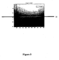
- the point of inflection I defines a scanning line 10 as represented in FIG. figure 5 .
- This scan line makes it possible to determine the visibility distance of the driver according to the characteristics of the camera.
- the calculated visibility distance may become incorrect because the horizon appears closer when the vehicle load increases. This uncertainty can be corrected by introducing the trim value of the vehicle obtained for example by means of the sensor as represented in FIG. figure 1 .
- initial or in-use calibration may be considered; this one searches for the limit of the horizon on a clear day and makes it possible to deduce the real visibility distance by compensation.
- This type of calibration can be achieved for example by a potentiometer or a software image processing.
- a detection signal can be emitted, thereby enabling the fog lamps to be turned on.
- the fog lights may be extinguished.
- Access to the visibility distance can also affect the intensity of the fog lamps depending on the impact of the fog on the visibility distance.
- the detection signal can thus serve as a control signal sent for example on a CAN (Controller Area Network) bus connected to a LCS (Light Control System) type card.
- CAN Controller Area Network
- LCS Light Control System
- This visibility distance also makes it possible to act directly on the speed of the vehicle, which can thus be regulated.
- homogeneity area search method has been described for division-fusion segmentation methods, but other segmentation methods may be used such as region division or region growth methods.
- the brightness has been described with reference to the gray level of the pixels of the image but it can also be represented by another magnitude depending on the image coding used.
- the method according to the invention has been described in the case of a fog detection but the method is also transferable to other elements disrupting the visibility of the driver such as rain, smoke or snow.
- the invention also relates to the motor vehicle using the method described above.
- the invention also relates to the possibility of modulating / adjusting the photometry of the light beam emitted by the traffic light or by the projector, in particular its light intensity.
- This modulation can be done by appropriately modulating the power supply of the light source or sources.
- This modulation is preferably controlled by means of an automated control system, taking into account one or more parameters determined by measurements obtained directly by one or more sensors or by calculation from this type of measurement.
- a particularly interesting parameter for this automated modulation is precisely the determination of the visibility distance described above.
- any other type of parameter can be chosen, such as the speed of the vehicle, or any measurement made by an infra-red camera in night vision, or any other type of camera or measuring instrument present on the vehicle, the measurement of the plate of the vehicle, or any data from a navigation system as the so-called GPS system (for Global positioning System).
- GPS system for Global positioning System
Description
La présente invention concerne un procédé et un dispositif de détermination de la distance de visibilité du conducteur d'un véhicule en présence d'un élément perturbant la visibilité dudit conducteur tel que le brouillard dans un champ de l'environnement du véhicule. Elle est particulièrement adaptée au domaine de l'éclairage et de la signalisation de véhicules routiers.The present invention relates to a method and a device for determining the visibility distance of the driver of a vehicle in the presence of an element disrupting the visibility of said driver such as fog in a field of the vehicle environment. It is particularly suited to the field of lighting and signaling of road vehicles.
L'invention concerne également un système de commande de projecteurs et/ou de feux antibrouillards et/ou de la vitesse du véhicule.The invention also relates to a control system of headlamps and / or fog lamps and / or the speed of the vehicle.
L'allumage et l'extinction des feux antibrouillards étaient initialement commandés manuellement par le conducteur grâce à un commutateur disposé sur le tableau de bord.The lighting and extinguishing of the fog lamps were initially manually controlled by the driver through a switch arranged on the dashboard.
Cependant, si le conducteur oublie de rendre actif ses feux de brouillard, il existe une situation de danger importante.However, if the driver forgets to activate his fog lights, there is a significant danger situation.
Inversement, l'utilisation des feux antibrouillards n'est pas toujours réalisée à bon escient par les conducteurs. Ainsi, l'utilisation à mauvais escient de ces feux, et en particulier des feux arrière de brouillard, peut provoquer une gêne du conducteur se trouvant derrière alors que les conditions de visibilité ne justifient pas l'utilisation de ces feux.Conversely, the use of fog lights is not always carried out wisely by the drivers. Thus, the misuse of these lights, and in particular rear fog lamps, can cause discomfort to the driver behind while the visibility conditions do not justify the use of these lights.
En effet, le conducteur se trouvant derrière peut être ébloui et ne pas distinguer rapidement un allumage des feux indicateurs de freinage du véhicule situé devant entraînant de ce fait un risque de collision.Indeed, the driver behind can be dazzled and do not quickly distinguish an ignition of the brake indicator lights of the vehicle in front thereby causing a risk of collision.
Afin de remédier aux problèmes mentionnés ci-dessus, plusieurs solutions ont été proposées visant à fournir des dispositifs de détection de la présence de brouillard pour commander automatiquement l'allumage des feux.In order to remedy the problems mentioned above, several solutions have been proposed to provide devices for detecting the presence of fog to automatically control the lighting of the lights.
Une première solution consiste à utiliser un détecteur de brouillard installé dans un feu arrière, ledit détecteur utilisant le principe de la retro-diffusion d'une lumière infrarouge sur les gouttelettes de brouillard.A first solution is to use a fog detector installed in a rear light, said detector using the principle of the retro-scattering of an infrared light on the mist droplets.
Toutefois, cette première solution est très perturbée par des phénomènes aérodynamiques tels que la turbulence des couches d'air situées sur l'arrière du véhicule. Sa sensibilité devient alors insuffisante.However, this first solution is very disturbed by aerodynamic phenomena such as the turbulence of the air layers located on the rear of the vehicle. His sensitivity then becomes insufficient.
Une seconde solution consiste à analyser un échantillon de brouillard parcourant une chambre de mesure évaluant la transmission et la diffusion créées par les particules d'eau.A second solution consists of analyzing a fog sample passing through a measurement chamber evaluating the transmission and diffusion created by the water particles.
Cependant, les effets parasites liés à l'intégration sur le véhicule, comme les variations de pression, de température ou de flux d'air conduisent à des résultats difficiles à interpréter.However, the parasitic effects associated with integration on the vehicle, such as pressure, temperature or airflow variations lead to results that are difficult to interpret.
Une troisième solution utilise des moyens de mesure de temps de vol de photons, utilisés notamment dans des systèmes anti-collision de type LIDAR (Light Detection and Ranging) permettant d'évaluer la transmission de l'atmosphère et donc de déduire la présence de brouillard.A third solution uses photon time of flight measurement means, used in particular in LIDAR (Light Detection and Ranging) type anti-collision systems for evaluating the transmission of the atmosphere and therefore to deduce the presence of fog. .
De tels systèmes sont cependant très coûteux ; de plus, la présence d'eau sur les moyens optiques de mesure suffit à fausser totalement les mesures.Such systems are however very expensive; moreover, the presence of water on the optical measuring means suffices to completely distort the measurements.
Une quatrième solution est proposée dans le document
Cette quatrième solution permet donc l'envoi d'un signal de commande entraînant l'allumage des feux en présence de brouillard. Elle pose cependant certaines difficultés.This fourth solution therefore allows the sending of a control signal causing the fires to light in the presence of fog. However, it poses some difficulties.
En effet, le procédé décrit fonctionne en tout ou rien ; il permet d'envoyer un signal de commande aux feux de brouillard selon qu'il y a ou non du brouillard mais il ne permet en aucun cas de quantifier la densité de brouillard et de déterminer ainsi la distance de visibilité du conducteur en présence de brouillard. Il ne permet donc pas d'agir sur l'intensité des feux ou sur la vitesse du véhicule en fonction de la visibilité du conducteur.Indeed, the described method works in all or nothing; it makes it possible to send a control signal to the fog lamps according to whether or not there is fog, but it does not in any way make it possible to quantify the fog density and thus to determine the distance of visibility of the driver in the presence of fog . It therefore does not allow to act on the intensity of the lights or on the speed of the vehicle according to the visibility of the driver.
Une dernière solution est connue de la publication
Cette publication décrit un procédé de détermination de la distance de visibilité du conducteur d'un véhicule en présence d'un élément perturbant ou modifiant la visibilité dudit conducteur dans un champ de l'environnement dudit véhicule, choisi parmi le brouillard, la fumée, la pluie ou la neige, comportant une étape de relevé d'au moins une image d'un champ de l'espace, ledit procédé comportant les étapes suivantes :
- séparation de ladite image par une bande verticale,
- détermination de la luminosité des pixels de ladite bande verticale en fonction de la position en hauteur desdits pixels sur ladite bande verticale,
- calcul du point d'inflexion de la courbe représentant ladite luminosité en fonction de ladite position,
- détermination de la distance de visibilité du conducteur dudit véhicule à partir de la position dudit point d'inflexion sur ladite image.
- separating said image by a vertical band,
- determining the brightness of the pixels of said vertical strip as a function of the height position of said pixels on said vertical strip,
- calculating the inflection point of the curve representing said brightness as a function of said position,
- determining the distance of visibility of the driver of said vehicle from the position of said point of inflection on said image.
Ce procédé de l'art antérieur est essentiellement basé sur la détermination d'une bande de mesure au centre de l'image, la largeur de cette bande étant paramétrable. Le choix d'une bande de mesure pose différents problèmes, tels qu'énoncés par exemple aux paragraphes 6.2 (page 42) et 6.3 (page 46) de ce document.This method of the prior art is essentially based on the determination of a measurement band in the center of the image, the width of this band being parameterizable. The choice of a measurement band poses various problems, as stated, for example, in paragraphs 6.2 (page 42) and 6.3 (page 46) of this document.
La présente invention vise à fournir à bas coût un procédé de détermination de la distance de visibilité du conducteur d'un véhicule en présence d'un élément perturbant la visibilité dudit conducteur dans un champ de l'environnement dudit véhicule permettant non seulement de commander de façon fiable et insensible aux turbulences aérodynamiques l'allumage et l'extinction des feux selon que l'élément est ou non présent mais aussi de déterminer la distance de visibilité du conducteur en présence dudit élément et d'agir sur l'intensité des feux ou sur la vitesse du véhicule en fonction de la visibilité du conducteur.The present invention aims to provide at a low cost a method for determining the visibility distance of the driver of a vehicle in the presence of an element disrupting the visibility of said driver in a field of the environment of said vehicle allowing not only control of reliable and insensitive to aerodynamic turbulence ignition and extinction of lights depending on whether the element is present or not but also to determine the distance of visibility of the driver in the presence of said element and to act on the intensity of the lights or on the speed of the vehicle according to the visibility of the driver.
La présente invention propose à cet effet un procédé de détermination de la distance de visibilité du conducteur d'un véhicule en présence d'un élément perturbant et/ou modifiant la visibilité dudit conducteur dans un champ de l'environnement dudit véhicule comportant une étape de relevé d'au moins une image d'un champ de l'espace, ledit procédé étant caractérisé en ce qu'il comporte les étapes suivantes :
- une étape de recherche des zones de ladite image répondant chacune à un prédicat d'homogénéité,
- une détermination du centre de gravité de chacune desdites zones,
- une détermination du centre de gravité global de chacun desdits centres de gravité desdites zones,
- une détermination d'une ligne verticale ou substantiellement verticale passant par ledit centre de gravité global,
- séparation de ladite image en deux parties par la ligne verticale ou substantiellement verticale passant par ledit centre de gravité global,
- détermination de la luminosité des pixels de ladite ligne verticale ou substantiellement verticale en fonction de la position en hauteur desdits pixels sur ladite ligne verticale ou substantiellement verticale,
- calcul du point d'inflexion de la courbe représentant ladite luminosité en fonction de ladite position,
- détermination de la distance de visibilité du conducteur dudit véhicule à partir de la position dudit point d'inflexion sur ladite image.
- a step of searching the zones of said image each responding to a predicate of homogeneity,
- a determination of the center of gravity of each of said zones,
- a determination of the overall center of gravity of each of said centers of gravity of said zones,
- a determination of a vertical or substantially vertical line passing through said global center of gravity,
- separating said image into two parts by the vertical or substantially vertical line passing through said global center of gravity,
- determining the brightness of the pixels of said vertical or substantially vertical line as a function of the height position of said pixels on said vertical or substantially vertical line,
- calculating the inflection point of the curve representing said brightness as a function of said position,
- determining the distance of visibility of the driver of said vehicle from the position of said point of inflection on said image.
On comprend par "substantiellement verticale " une ligne qui est verticale ou qui est inclinée d'un angle faible par rapport à la verticale (par exemple de quelques degrés, notamment de 0.5 à 15°).By "substantially vertical" is meant a line which is vertical or which is inclined at a small angle to the vertical (for example a few degrees, in particular from 0.5 to 15 °).
Grâce à l'invention, le relevé d'image par un dispositif du type caméra est insensible aux turbulences atmosphériques à proximité du véhicule.Thanks to the invention, the image recording by a device of the camera type is insensitive to atmospheric turbulence in the vicinity of the vehicle.
De plus, le procédé permet non seulement de déclencher les feux antibrouillards mais il quantifie également la visibilité du conducteur et permet ainsi d'agir sur l'intensité desdits feux ou sur la vitesse du véhicule.In addition, the method not only triggers the fog lights but it also quantifies the visibility of the driver and thus allows to act on the intensity of said lights or the speed of the vehicle.
Le procédé est économique dans la mesure où la caméra et le traitement peuvent être dédiés à d'autres fonctions telles que le suivi de non-dépassement d'une ligne blanche, l'anticipation d'un virage ou la vision nocturne par caméra infrarouge.The method is economical in that the camera and the processing can be dedicated to other functions such as tracking a white line, anticipating a turn or night vision by infrared camera.
Le relevé d'image peut se faire aisément en plaçant par exemple une caméra derrière le pare brise, dans un autre lieu bénéficiant d'essuie-glace ou de lave glace tel que le projecteur, ou à tout autre endroit approprié du véhicule.The image can be easily done by placing for example a camera behind the windshield, in another place with windshield wiper or washer such as the projector, or any other appropriate place of the vehicle.
Avantageusement, ledit élément perturbant la visibilité dudit conducteur est choisi parmi le brouillard, la fumée, la pluie ou la neige.Advantageously, said element disturbing the visibility of said driver is selected from fog, smoke, rain or snow.
De manière avantageuse, ledit procédé comporte une étape d'émission d'un signal de détection lorsque ladite distance de visibilité passe au-dessous d'un certain seuil.Advantageously, said method comprises a step of transmitting a detection signal when said visibility distance passes below a certain threshold.
Ce mode de réalisation est plus précis que l'utilisation d'une ligne verticale passant par le centre de l'image.This embodiment is more accurate than using a vertical line passing through the center of the image.
Avantageusement, ladite étape de recherche des zones de ladite image répondant chacune à un prédicat d'homogénéité est réalisée par une méthode de segmentation par division-fusion telle que la méthode tetra-arbre (Quadtree en anglais).Advantageously, said step of searching the zones of said image each responding to a predicate of homogeneity is carried out by a splitting-fusion segmentation method such as the tetra-tree method (Quadtree in English).
De manière avantageuse, ladite luminosité desdits pixels est représentée par un niveau de gris.Advantageously, said brightness of said pixels is represented by a gray level.
Avantageusement, le calcul du point d'inflexion de la courbe représentant ladite luminosité en fonction de ladite position est réalisé en dérivant ladite courbe.Advantageously, the calculation of the inflection point of the curve representing said brightness as a function of said position is achieved by deriving said curve.
Avantageusement, ladite distance de visibilité est corrigée en prenant en compte l'assiette dudit véhicule.Advantageously, said visibility distance is corrected taking into account the attitude of said vehicle.
Selon un mode de réalisation très avantageux, ledit procédé comporte une étape préalable de calibrage déterminant la limite de l'horizon par temps clair.According to a very advantageous embodiment, said method comprises a preliminary calibration step determining the limit of the horizon in clear weather.
La présente invention a également pour objet un dispositif pour la mise en oeuvre du procédé selon l'invention comportant une caméra pour relever au moins une image d'un champ de l'espace, ledit dispositif étant caractérisé en ce qu'il comporte :
- des moyens pour rechercher des zones de ladite image répondant chacune à un prédicat d'homogénéité,
- des moyens pour déterminer le centre de gravité de chacune desdites zones,
- des moyens pour déterminer le centre de gravité global de chacun desdits centres de gravité desdites zones,
- des moyens pour déterminer une ligne verticale ou substantiellement verticale passant par ledit centre de gravité global,
- des moyens pour séparer ladite image en deux parties par une ligne verticale ou substantiellement verticale passant par ledit centre de gravité global,
- des moyens pour déterminer la luminosité des pixels de ladite ligne verticale ou substantiellement verticale en fonction de la position en hauteur desdits pixels sur ladite ligne verticale ou substantiellement verticale,
- des moyens de calcul du point d'inflexion de la courbe représentant ladite luminosité en fonction de ladite position,
- des moyens de détermination de la distance de visibilité du conducteur dudit véhicule à partir de la position dudit point d'inflexion sur ladite image,
- means for searching areas of said image each responding to a predicate of homogeneity,
- means for determining the center of gravity of each of said zones,
- means for determining the overall center of gravity of each of said centers of gravity of said zones,
- means for determining a vertical or substantially vertical line passing through said global center of gravity,
- means for separating said two-part image by a vertical or substantially vertical line passing through said overall center of gravity,
- means for determining the brightness of the pixels of said vertical or substantially vertical line as a function of the height position of said pixels on said vertical or substantially vertical line,
- means for calculating the inflection point of the curve representing said brightness as a function of said position,
- means for determining the visibility distance of the driver of said vehicle from the position of said point of inflection on said image,
De manière avantageuse, ledit dispositif comporte un dispositif émetteur d'un signal de commande fonction de ladite distance de visibilité.Advantageously, said device comprises a device transmitting a control signal function of said visibility distance.
De manière avantageuse, ledit dispositif comporte des moyens pour détecter le passage de ladite distance de visibilité au-dessous d'un certain seuil.Advantageously, said device comprises means for detecting the passage of said visibility distance below a certain threshold.
Selon un premier mode de réalisation de l'invention, ladite caméra se situe derrière le pare brise dudit véhicule.According to a first embodiment of the invention, said camera is located behind the windshield of said vehicle.
Selon un deuxième mode de réalisation de l'invention, ladite caméra se situe dans le projecteur dudit véhicule.According to a second embodiment of the invention, said camera is in the projector of said vehicle.
La présente invention a en outre pour objet un système de commande d'au moins un projecteur et/ou d'un feu antibrouillard de véhicule caractérisé en ce qu'il comporte un dispositif selon l'invention dont ledit dispositif émetteur est relié aux organes de puissance dudit projecteur et/ou dudit feu, ledit signal de commande commandant l'allumage et/ou l'intensité dudit feu et/ou dudit projecteur en fonction de ladite distance de visibilité.The subject of the present invention is furthermore a control system for at least one headlamp and / or a vehicle fog lamp, characterized in that it comprises a device according to the invention of which said emitter device is connected to the body members. power of said projector and / or said fire, said control signal controlling the ignition and / or intensity of said fire and / or said projector according to said visibility distance.
Ainsi, le système peut faire varier l'intensité du feu ou du projecteur en prenant en considération la valeur de la distance de visibilité contrairement à un système tout ou rien.Thus, the system can vary the intensity of the fire or the projector taking into consideration the value of the visibility distance in contrast to an all-or-nothing system.
La présente invention a enfin pour objet un système de régulation de la vitesse d'un véhicule caractérisé en ce qu'il comporte un dispositif selon l'invention dont ledit dispositif émetteur est relié à un organe de commande de la vitesse du véhicule, ledit signal de commande régulant la vitesse du véhicule en fonction de ladite distance de visibilité.Finally, a subject of the present invention is a system for regulating the speed of a vehicle, characterized in that it comprises a device according to the invention, of which said transmitting device is connected to a vehicle speed control member, said signal controlling the speed of the vehicle according to said visibility distance.
D'autres caractéristiques et avantages de la présente invention apparaîtront dans la description suivante d'un mode de réalisation de l'invention donné à titre illustratif et nullement limitatif.Other features and advantages of the present invention will appear in the following description of an embodiment of the invention given by way of illustration and not limiting.
Dans les figures suivantes :
- La
figure 1 représente schématiquement un dispositif pour la mise en oeuvre du procédé selon l'invention, - La
figure 2 représente une image telle que relevée dans le procédé selon l'invention, - La
figure 3 représente une courbe de luminosité obtenue à partir de l'image représentée enfigure 2 , - La
figure 4 représente une courbe dérivée de la courbe de luminosité représentée enfigure 3 , - La
figure 5 représente l'image représentée enfigure 2 sur laquelle est insérée une ligne de visibilité.
- The
figure 1 schematically represents a device for implementing the method according to the invention, - The
figure 2 represents an image as recorded in the process according to the invention, - The
figure 3 represents a luminosity curve obtained from the image represented infigure 2 , - The
figure 4 represents a curve derived from the luminosity curve represented infigure 3 , - The
figure 5 represents the image represented infigure 2 on which is inserted a line of sight.
Dans toutes les figures, les éléments communs portent les mêmes numéros de référence.In all the figures, the common elements bear the same reference numbers.
La
Le dispostif 1 comporte :
une caméra 2,- des moyens 3 pour déterminer une distance de visibilité d'un conducteur du véhicule,
- des moyens 4 pour calculer l'assiette du véhicule,
un capteur 5.
- a
camera 2, - means 3 for determining a visibility distance of a driver of the vehicle,
- means 4 for calculating the attitude of the vehicle,
- a
sensor 5.
La caméra 2 se trouve préférentiellement derrière le pare-brise du véhicule de façon à être dans une zone balayée par les essuie-glace.The
La caméra 2 saisit une image I située devant le véhicule pour anticiper l'allumage de projecteurs avant l'entrée dans une zone de brouillard.The
L'image I est traitée par les moyens 3 pour déterminer la distance de visibilité D du conducteur.The image I is processed by the
Les moyens 3 pour déterminer D sont des moyens logiciels et seront expliqués plus en détail en référence avec les
Le capteur 5 se trouve préférentiellement sur la suspension du véhicule et permet de fournir des informations aux moyens 4 pour calculer l'assiette du véhicule.The
Selon une alternative, les moyens 3 de détermination de D peuvent prendre en considération l'assiette calculée par les moyens 4 pour ajuster la distance de visibilité D.According to an alternative, the
La
L'image 6 représente un champ de l'environnement du véhicule représentant une route en présence de brouillard ; elle comporte un ensemble de pixels représentant chacun des points de l'image dont la luminosité va du noir au blanc. Chaque pixel est par exemple codé sur un octet avec 256 niveaux de gris possibles. Les points de l'image peuvent être repérés en hauteur par les lignes de balayage de l'image variant de 0 à 250.The
Les moyens 3 de détermination de la distance de visibilité du conducteur tels que représentés en
Cette recherche peut par exemple être réalisée à l'aide d'une méthode de segmentation par division-fusion telle que la méthode tetra-arbre (Quadtree en anglais) ; le tetra-arbre possède une pluralité de noeuds, chaque noeud possédant exactement quatre noeuds fils, excepté les noeuds terminaux. Chaque noeud correspond à un bloc, c'est à dire à une zone de l'image de forme carrée. Chaque bloc associé à un noeud est analysé de façon récursive afin de décider s'il doit être divisé en quatre sous-blocs. L'analyse récursive s'arrête lorsque chacun des sous-blocs respecte un prédicat d'homogénéité colorimétrique utilisant des matrices de cooccurrence.This search can for example be carried out using a division-fusion segmentation method such as the tetra-tree method (Quadtree in English); the tetra-tree has a plurality of nodes, each node having exactly four child nodes, except the terminal nodes. Each node corresponds to a block, that is to say to a zone of the square-shaped image. Each block associated with a node is recursively analyzed to decide whether it should be divided into four sub-blocks. Recursive analysis stops when each of the sub-blocks respects a colorimetric homogeneity predicate using co-occurrence matrices.
D'autres méthodes telles que les algorithmes de k-means peuvent également être utilisées.Other methods such as k-means algorithms can also be used.
L'application de la recherche de zones d'homogénéité permet de définir deux régions sur l'image 6 ayant respectivement pour centres de gravité G1 et G2.The application of the search for zones of homogeneity makes it possible to define two regions on the
On calcule ensuite le centre de gravité G des deux centres de gravité G1 et G2 par lequel on fait passer une ligne verticale 7.The center of gravity G of the two centers of gravity G1 and G2 is then calculated by means of which a
Chacun des points de la ligne verticale 7 peut être caractérisé par une ligne de balayage et une luminosité correspondant à un certain niveau de gris.Each of the points of the
La
La courbe 8 représente en ordonnée, la valeur du niveau de gris des points de la ligne 7 représentée en
Ainsi, le point A correspond à la ligne de balayage 0 et a un niveau de gris égal à environ 220.Thus, the point A corresponds to the
De même, le point B correspond à la ligne de balayage 250 et a un niveau de gris égal à environ 40.Similarly, the point B corresponds to the
La
Cette courbe 9 présente un minimum M correspondant à un point d'inflexion I de la courbe 8 telle que représentée en
Le point d'inflexion I définit une ligne de balayage 10 telle que représenté en
En fonction de la charge du véhicule, la distance de visibilité calculée peut devenir erronée car l'horizon semble plus proche quand la charge du véhicule augmente. Cette incertitude peut être corrigée en introduisant la valeur d'assiette du véhicule obtenue par exemple grâce au capteur tel que représenté en
En complément, un calibrage initial ou en cours d'utilisation peut être envisagé ; celui-ci recherche la limite de l'horizon par temps clair et permet de déduire la distance de visibilité réelle par compensation. Ce type de calibrage peut être réalisé par exemple par un potentiomètre ou un traitement logiciel de l'image.In addition, initial or in-use calibration may be considered; this one searches for the limit of the horizon on a clear day and makes it possible to deduce the real visibility distance by compensation. This type of calibration can be achieved for example by a potentiometer or a software image processing.
Lorsque la distance de visibilité passe au-dessous d'un certain seuil, un signal de détection peut être émis, permettant de ce fait l'allumage les feux antibrouillards.When the sight distance falls below a certain threshold, a detection signal can be emitted, thereby enabling the fog lamps to be turned on.
De même, lorsque la distance de visibilité redevient normale, les feux antibrouillards peuvent être éteints.Likewise, when the sight distance becomes normal again, the fog lights may be extinguished.
L'accès à la distance de visibilité permet d'agir en outre sur l'intensité des feux antibrouillards en fonction de l'impact du brouillard sur la distance de visibilité.Access to the visibility distance can also affect the intensity of the fog lamps depending on the impact of the fog on the visibility distance.
Le signal de détection peut ainsi servir de signal de commande envoyé par exemple sur un bus CAN (Controller Area Network) relié à une carte du type LCS (Light Control System).The detection signal can thus serve as a control signal sent for example on a CAN (Controller Area Network) bus connected to a LCS (Light Control System) type card.
Cette distance de visibilité permet également d'agir directement sur la vitesse du véhicule qui peut être ainsi régulée.This visibility distance also makes it possible to act directly on the speed of the vehicle, which can thus be regulated.
Bien entendu, l'invention n'est pas limitée au mode de réalisation qui vient d'être décrit.Of course, the invention is not limited to the embodiment just described.
Notamment, la méthode de recherche des zones d'homogénéité a été décrite dans le cas des méthodes de segmentation par division-fusion mais d'autres méthodes de segmentation peuvent être utilisées telles que les méthodes par division de régions ou par croissance de régions.In particular, the homogeneity area search method has been described for division-fusion segmentation methods, but other segmentation methods may be used such as region division or region growth methods.
En outre, la luminosité a été décrite en référence avec le niveau de gris des pixels de l'image mais elle peut également être représentée par une autre grandeur en fonction du codage d'image utilisé.In addition, the brightness has been described with reference to the gray level of the pixels of the image but it can also be represented by another magnitude depending on the image coding used.
De même, le procédé selon l'invention a été décrit dans le cas d'une détection de brouillard mais le procédé est également transposable à d'autres éléments perturbant la visibilité du conducteur tels que la pluie, la fumée ou la neige.Similarly, the method according to the invention has been described in the case of a fog detection but the method is also transferable to other elements disrupting the visibility of the driver such as rain, smoke or snow.
L'invention concerne aussi le véhicule automobile utilisant le procédé décrit plus haut.The invention also relates to the motor vehicle using the method described above.
L'invention concerne également la possibilité de moduler/ajuster la photométrie du faisceau lumineux émis par le feu de signalisation ou par le projecteur, notamment son intensité lumineuse. Cette modulation peut se faire en modulant de façon appropriée l'alimentation électrique de la ou des sources lumineuses. Cette modulation est de préférence commandée à l'aide d' un système de régulation automatisé, prenant en compte un ou plusieurs paramètres déterminés par des mesures obtenues directement par un ou plusieurs capteurs ou par calcul à partir de ce type de mesure. Un paramètre particulièrement intéressant pour cette modulation automatisée est justement la détermination de la distance de visibilité décrite plus haut. Mais tout autre type de paramètre peut être choisi, comme la vitesse du véhicule, ou toute mesure faite par une caméra infra-rouge en vision de nuit, ou tout autre type de caméra ou instrument de mesure présent sur le véhicule, la mesure de l'assiette du véhicule, ou toute donnée émanant d'un système de navigation comme le système dit GPS (pour Global positioning System).The invention also relates to the possibility of modulating / adjusting the photometry of the light beam emitted by the traffic light or by the projector, in particular its light intensity. This modulation can be done by appropriately modulating the power supply of the light source or sources. This modulation is preferably controlled by means of an automated control system, taking into account one or more parameters determined by measurements obtained directly by one or more sensors or by calculation from this type of measurement. A particularly interesting parameter for this automated modulation is precisely the determination of the visibility distance described above. But any other type of parameter can be chosen, such as the speed of the vehicle, or any measurement made by an infra-red camera in night vision, or any other type of camera or measuring instrument present on the vehicle, the measurement of the plate of the vehicle, or any data from a navigation system as the so-called GPS system (for Global positioning System).
Claims (14)
- Method for determining the visibility distance (D) of the driver of a vehicle in the presence of something which disturbs or alters the said driver's visibility in a field of the environment of the said vehicle, selected from mist, smoke, rain or snow, comprising a stage of identifying at least one image (6) in a field of space, the said method being characterised in that it comprises the following stages:- a stage of searching zones of the said image each responding to a uniformity attribute,- determination of the centre of gravity (G1, G2) of each of the said zones,- determination of the overall centre of gravity (G) of each of the said centres of gravity (G1, G2) of the said zones,- determination of a vertical or substantially vertical line (7) passing through the said overall centre of gravity (G),- separation of the said image into two parts by the vertical or substantially vertical line (7) passing through the said overall centre of gravity (G),- determining of the luminosity of the pixels of the said vertical or substantially vertical line (7) in relation to the height position of the said pixels on the said vertical or substantially vertical line (7),- calculation of the inflection point (I) in the graph (8) representing the said luminosity as a function of the said position,- determination of the visibility distance (D) of the driver of the said vehicle from the position of the said inflection point (I) on the said image (6).
- Method according to the preceding claim, characterised in that it comprises a stage of emitting a detection signal when the said visibility distance (D) falls beneath a particular threshold.
- Method according to claim 1, characterised in that the said stage of searching the zones of the said image each responding to a uniformity attribute is carried out using a division/fusion segmentation method.
- Method according to any one of the preceding claims, characterised in that the said luminosity of the said pixels is represented by a grey level.
- Method according to any one of the preceding claims, characterised in that calculation of the inflection point on the graph representing the said luminosity as a function of the said position is carried out by obtaining the derivative (9) of the said graph.
- Method according to any one of the preceding claims, characterised in that the said visibility distance is corrected taking the trim of the said vehicle into account.
- Method according to any one of the preceding claims, characterised in that it comprises a prior calibration stage determining the limit of the horizon in clear weather.
- Device (1) for implementing the method according to any one of the preceding claims, comprising a camera (2) to obtain at least one image of a field of space, the said device being characterised in that it comprises:- means for searching zones of the said image each responding to a uniformity attribute,- means for determining the centre of gravity (G1, G2) of each of the said zones,- means for determining the overall centre of gravity (G) of each of the said centres of gravity (G1, G2) of the said zones,- means for determining a vertical or substantially vertical line (7) passing through the said overall centre of gravity (G),- means for separating the said image into two parts by means of a vertical or substantially vertical line (7) passing through the said overall centre of gravity (G),- means for determining the luminosity of the pixels in the said vertical or substantially vertical line (7) as a function of the height position of the said pixels on the said vertical or substantially vertical line,- means for calculating the inflexion point of the graph representing the said luminosity as a function of the said position,- means for determining the visibility distance of the driver of the said vehicle from the position of the said inflexion point on the said image.
- Device according to claim 8, characterised in that the said camera is located behind the windscreen of the said vehicle.
- Device according to claim 8, characterised in that the said camera is located in the headlamp of the said vehicle.
- Device according to any one of claims 8 to 10 comprising a device emitting a command signal which is a function of the said visibility distance.
- Device according to any one of claims 8 to 11 comprising means for detecting when the said visibility distance passes below a particular threshold.
- System for controlling at least one vehicle headlamp and/or fog lamp characterised in that it comprises a device according to either of claims 11 or 12 in which the said emitting device is connected to the systems powering the said headlamp and/or said lamp, the said command signal controlling the lighting up and/or intensity of the said lamp and/or said headlamp in relation to the said visibility distance.
- System for controlling the speed of a vehicle characterised in that it comprises a device according to either of claims 11 or 12 in which the said emitter device is connected to a system controlling the speed of the vehicle, the said command signal controlling the speed of the vehicle in relation to the said visibility distance.
Applications Claiming Priority (2)
| Application Number | Priority Date | Filing Date | Title |
|---|---|---|---|
| FR0214775A FR2847367B1 (en) | 2002-11-19 | 2002-11-19 | METHOD AND DEVICE FOR DETERMINING THE VISIBILITY DISTANCE OF THE DRIVER OF A VEHICLE |
| FR0214775 | 2002-11-19 |
Publications (2)
| Publication Number | Publication Date |
|---|---|
| EP1422663A1 EP1422663A1 (en) | 2004-05-26 |
| EP1422663B1 true EP1422663B1 (en) | 2014-04-16 |
Family
ID=32187814
Family Applications (1)
| Application Number | Title | Priority Date | Filing Date |
|---|---|---|---|
| EP03292599.2A Expired - Lifetime EP1422663B1 (en) | 2002-11-19 | 2003-10-17 | Method and apparatus for determining the distance of visibility of the driver of a vehicle |
Country Status (2)
| Country | Link |
|---|---|
| EP (1) | EP1422663B1 (en) |
| FR (1) | FR2847367B1 (en) |
Cited By (2)
| Publication number | Priority date | Publication date | Assignee | Title |
|---|---|---|---|---|
| US10668924B2 (en) | 2016-11-29 | 2020-06-02 | Samsung Electronics Co., Ltd. | Method and apparatus to control velocity of vehicle |
| DE102019208762A1 (en) * | 2019-06-17 | 2020-12-17 | Conti Temic Microelectronic Gmbh | Method for controlling vehicle headlights |
Families Citing this family (14)
| Publication number | Priority date | Publication date | Assignee | Title |
|---|---|---|---|---|
| DE102004004190A1 (en) * | 2004-01-28 | 2005-08-25 | Opel Eisenach Gmbh | Motor vehicle with a rear fog lamp and a driver assistance system |
| FR2876826B1 (en) * | 2004-10-19 | 2007-03-02 | France Etat Ponts Chaussees | DEVICE FOR MEASURING VISIBILITY DISTANCE |
| FR2884637B1 (en) * | 2005-04-19 | 2007-06-29 | Valeo Vision Sa | METHOD OF DETECTING NIGHT MIST AND SYSTEM FOR IMPLEMENTING SAID METHOD |
| FR2885860B1 (en) | 2005-05-20 | 2007-08-17 | Valeo Vision Sa | DEVICE FOR DETECTING OBSTACLES COMPRISING AN IMAGING SYSTEM FOR A MOTOR VEHICLE |
| FR2902556B1 (en) * | 2006-06-15 | 2008-08-15 | Valeo Vision Sa | METHOD FOR DETERMINING A VISIBILITY DISTANCE FOR A DRIVER OF A VEHICLE |
| JP4241834B2 (en) | 2007-01-11 | 2009-03-18 | 株式会社デンソー | In-vehicle fog determination device |
| JP4321591B2 (en) | 2007-01-11 | 2009-08-26 | 株式会社デンソー | In-vehicle fog determination device |
| FR2919727B1 (en) * | 2007-08-03 | 2010-07-30 | Valeo Vision | METHOD FOR DETECTION BY A VEHICLE OF A VISIBILITY DISPERSING PHENOMENON |
| FR2922506B1 (en) | 2007-10-18 | 2010-03-19 | Renault Sas | METHODS FOR MEASURING THE VISIBILITY DISTANCE OF A MOTOR VEHICLE DRIVER AND CALCULATING A VEHICLE SPEED SET, AND SYSTEMS FOR THEIR IMPLEMENTATION |
| FR2923016B1 (en) * | 2007-10-31 | 2009-11-20 | Valeo Vision | METHOD FOR DETECTING A VISIBILITY DISRUPTION PHENOMENON FOR A VEHICLE. |
| FR2923933B1 (en) | 2007-11-16 | 2010-03-26 | Valeo Vision | METHOD FOR DETECTING A VISIBILITY DISRUPTION PHENOMENON FOR A VEHICLE |
| DE102008001551A1 (en) * | 2008-05-05 | 2009-11-12 | Robert Bosch Gmbh | Device and method for automatically adjusting the luminance of a light emitted by a lighting device of a vehicle light beam as a function of the visibility |
| WO2016073590A1 (en) | 2014-11-06 | 2016-05-12 | Gentex Corporation | System and method for visibility range detection |
| CN111932560B (en) * | 2020-09-21 | 2021-01-15 | 南京安通气象数据有限公司 | Method and device for calculating distance of low-visibility video image of road traffic |
Family Cites Families (4)
| Publication number | Priority date | Publication date | Assignee | Title |
|---|---|---|---|---|
| FR2710014B1 (en) * | 1993-09-15 | 1995-12-08 | Valeo Vision | Device for automatically controlling the orientation of the headlights of a motor vehicle as a function of the variation in attitude thereof. |
| DE59509929D1 (en) * | 1994-07-06 | 2002-01-24 | Volkswagen Ag | Method for determining the visibility, in particular for the movement of a motor vehicle |
| WO1997016926A1 (en) * | 1995-10-31 | 1997-05-09 | Sarnoff Corporation | Method and apparatus for determining ambient conditions from an image sequence |
| DE10034461A1 (en) * | 2000-07-15 | 2002-01-31 | Bosch Gmbh Robert | Procedure for determining visibility |
-
2002
- 2002-11-19 FR FR0214775A patent/FR2847367B1/en not_active Expired - Fee Related
-
2003
- 2003-10-17 EP EP03292599.2A patent/EP1422663B1/en not_active Expired - Lifetime
Non-Patent Citations (1)
| Title |
|---|
| HAUTIERE N: "AMELIORATION ET EXTENSION D'UN DETECTEUR DE BROUILLARD EMBARQUE", MEMOIRE DE DEA, UNIVERSITE JEAN MONNET, SAINT-ETIENNE, FR, 12 September 2002 (2002-09-12), Laboratoire LIVIC, INRETS/LCPC, pages 1 - 113, XP008044586 * |
Cited By (2)
| Publication number | Priority date | Publication date | Assignee | Title |
|---|---|---|---|---|
| US10668924B2 (en) | 2016-11-29 | 2020-06-02 | Samsung Electronics Co., Ltd. | Method and apparatus to control velocity of vehicle |
| DE102019208762A1 (en) * | 2019-06-17 | 2020-12-17 | Conti Temic Microelectronic Gmbh | Method for controlling vehicle headlights |
Also Published As
| Publication number | Publication date |
|---|---|
| FR2847367B1 (en) | 2005-01-14 |
| FR2847367A1 (en) | 2004-05-21 |
| EP1422663A1 (en) | 2004-05-26 |
Similar Documents
| Publication | Publication Date | Title |
|---|---|---|
| EP1422663B1 (en) | Method and apparatus for determining the distance of visibility of the driver of a vehicle | |
| EP1715456B1 (en) | Method for detecting night fog and system implementing said method | |
| EP2020595B1 (en) | Method for a vehicle to detect a phenomenon affecting visibility | |
| EP3084511B1 (en) | System and method for controlling the luminosity of a head-up display and display using said system | |
| FR2903493A1 (en) | Visibility condition determining device for vehicle, has image processing electronic control unit determining visibility condition outside of vehicle based on brightness of non-irradiated area in image that is picked up by camera | |
| KR100874461B1 (en) | External lighting control device of vehicle and automatic control device of vehicle | |
| EP2061006B1 (en) | Method of detecting a phenomenon that can reduce visibility for a vehicle | |
| EP2056093B1 (en) | Method for detection of a phenomenon perturbating the visibility for a vehicule | |
| FR2965354A1 (en) | METHOD AND DEVICE FOR DETECTING FOG, NIGHT | |
| EP3059121B1 (en) | Generation and remote processing of photometry | |
| WO2021122329A1 (en) | Method for controlling a motor vehicle lighting system | |
| EP1580074B1 (en) | Method for detecting a wet road and illumination system to implement the method | |
| FR3040350A1 (en) | DRIVING ASSIST DEVICE FOR VEHICLE, BASED ON BRIGHTNESS TO COME IN FRONT OF THE VEHICLE | |
| FR3107873A1 (en) | Method and device for controlling a vehicle in a risky meteorological area | |
| FR3104674A1 (en) | Method of controlling a lighting system of a motor vehicle | |
| FR3079614A1 (en) | METHOD AND DEVICE FOR MEASURING VISIBILITY CONDITIONS | |
| WO2022180253A1 (en) | Method for controlling a motor vehicle lighting system | |
| FR3104087A1 (en) | Method and control system of a motor vehicle lighting system capable of controlling the high beam according to driving conditions | |
| FR3117299A1 (en) | Method for controlling an interior lighting system of a motor vehicle | |
| FR3090073A1 (en) | Motor vehicle light module | |
| FR3105143A1 (en) | Method for detecting a local condition of the road on which a motor vehicle is traveling | |
| WO2022112192A1 (en) | Method for controlling a lighting system using a non-glare lighting function | |
| FR3122800A1 (en) | Method, device and system for controlling vehicle lights | |
| FR2939194A1 (en) | BRIGHTNESS SENSOR, IN PARTICULAR FOR MOTOR VEHICLE | |
| FR3127355A1 (en) | method for selecting an operating mode of an image capture device for facial recognition |
Legal Events
| Date | Code | Title | Description |
|---|---|---|---|
| PUAI | Public reference made under article 153(3) epc to a published international application that has entered the european phase |
Free format text: ORIGINAL CODE: 0009012 |
|
| AK | Designated contracting states |
Kind code of ref document: A1 Designated state(s): AT BE BG CH CY CZ DE DK EE ES FI FR GB GR HU IE IT LI LU MC NL PT RO SE SI SK TR |
|
| AX | Request for extension of the european patent |
Extension state: AL LT LV MK |
|
| 17P | Request for examination filed |
Effective date: 20041015 |
|
| AKX | Designation fees paid |
Designated state(s): AT BE BG CH CY CZ DE DK EE ES FI FR GB GR HU IE IT LI LU MC NL PT RO SE SI SK TR |
|
| 17Q | First examination report despatched |
Effective date: 20050128 |
|
| GRAP | Despatch of communication of intention to grant a patent |
Free format text: ORIGINAL CODE: EPIDOSNIGR1 |
|
| INTG | Intention to grant announced |
Effective date: 20131107 |
|
| GRAS | Grant fee paid |
Free format text: ORIGINAL CODE: EPIDOSNIGR3 |
|
| GRAA | (expected) grant |
Free format text: ORIGINAL CODE: 0009210 |
|
| AK | Designated contracting states |
Kind code of ref document: B1 Designated state(s): AT BE BG CH CY CZ DE DK EE ES FI FR GB GR HU IE IT LI LU MC NL PT RO SE SI SK TR |
|
| REG | Reference to a national code |
Ref country code: GB Ref legal event code: FG4D Free format text: NOT ENGLISH |
|
| REG | Reference to a national code |
Ref country code: CH Ref legal event code: EP |
|
| REG | Reference to a national code |
Ref country code: AT Ref legal event code: REF Ref document number: 662947 Country of ref document: AT Kind code of ref document: T Effective date: 20140515 |
|
| REG | Reference to a national code |
Ref country code: IE Ref legal event code: FG4D Free format text: LANGUAGE OF EP DOCUMENT: FRENCH |
|
| REG | Reference to a national code |
Ref country code: DE Ref legal event code: R096 Ref document number: 60346011 Country of ref document: DE Effective date: 20140528 |
|
| REG | Reference to a national code |
Ref country code: AT Ref legal event code: MK05 Ref document number: 662947 Country of ref document: AT Kind code of ref document: T Effective date: 20140416 |
|
| REG | Reference to a national code |
Ref country code: NL Ref legal event code: VDEP Effective date: 20140416 |
|
| PG25 | Lapsed in a contracting state [announced via postgrant information from national office to epo] |
Ref country code: FI Free format text: LAPSE BECAUSE OF FAILURE TO SUBMIT A TRANSLATION OF THE DESCRIPTION OR TO PAY THE FEE WITHIN THE PRESCRIBED TIME-LIMIT Effective date: 20140416 Ref country code: NL Free format text: LAPSE BECAUSE OF FAILURE TO SUBMIT A TRANSLATION OF THE DESCRIPTION OR TO PAY THE FEE WITHIN THE PRESCRIBED TIME-LIMIT Effective date: 20140416 Ref country code: GR Free format text: LAPSE BECAUSE OF FAILURE TO SUBMIT A TRANSLATION OF THE DESCRIPTION OR TO PAY THE FEE WITHIN THE PRESCRIBED TIME-LIMIT Effective date: 20140717 Ref country code: CY Free format text: LAPSE BECAUSE OF FAILURE TO SUBMIT A TRANSLATION OF THE DESCRIPTION OR TO PAY THE FEE WITHIN THE PRESCRIBED TIME-LIMIT Effective date: 20140416 Ref country code: BG Free format text: LAPSE BECAUSE OF FAILURE TO SUBMIT A TRANSLATION OF THE DESCRIPTION OR TO PAY THE FEE WITHIN THE PRESCRIBED TIME-LIMIT Effective date: 20140716 |
|
| PG25 | Lapsed in a contracting state [announced via postgrant information from national office to epo] |
Ref country code: SE Free format text: LAPSE BECAUSE OF FAILURE TO SUBMIT A TRANSLATION OF THE DESCRIPTION OR TO PAY THE FEE WITHIN THE PRESCRIBED TIME-LIMIT Effective date: 20140416 Ref country code: ES Free format text: LAPSE BECAUSE OF FAILURE TO SUBMIT A TRANSLATION OF THE DESCRIPTION OR TO PAY THE FEE WITHIN THE PRESCRIBED TIME-LIMIT Effective date: 20140416 Ref country code: AT Free format text: LAPSE BECAUSE OF FAILURE TO SUBMIT A TRANSLATION OF THE DESCRIPTION OR TO PAY THE FEE WITHIN THE PRESCRIBED TIME-LIMIT Effective date: 20140416 |
|
| PG25 | Lapsed in a contracting state [announced via postgrant information from national office to epo] |
Ref country code: PT Free format text: LAPSE BECAUSE OF FAILURE TO SUBMIT A TRANSLATION OF THE DESCRIPTION OR TO PAY THE FEE WITHIN THE PRESCRIBED TIME-LIMIT Effective date: 20140818 |
|
| REG | Reference to a national code |
Ref country code: DE Ref legal event code: R097 Ref document number: 60346011 Country of ref document: DE |
|
| PG25 | Lapsed in a contracting state [announced via postgrant information from national office to epo] |
Ref country code: SK Free format text: LAPSE BECAUSE OF FAILURE TO SUBMIT A TRANSLATION OF THE DESCRIPTION OR TO PAY THE FEE WITHIN THE PRESCRIBED TIME-LIMIT Effective date: 20140416 Ref country code: EE Free format text: LAPSE BECAUSE OF FAILURE TO SUBMIT A TRANSLATION OF THE DESCRIPTION OR TO PAY THE FEE WITHIN THE PRESCRIBED TIME-LIMIT Effective date: 20140416 Ref country code: DK Free format text: LAPSE BECAUSE OF FAILURE TO SUBMIT A TRANSLATION OF THE DESCRIPTION OR TO PAY THE FEE WITHIN THE PRESCRIBED TIME-LIMIT Effective date: 20140416 Ref country code: CZ Free format text: LAPSE BECAUSE OF FAILURE TO SUBMIT A TRANSLATION OF THE DESCRIPTION OR TO PAY THE FEE WITHIN THE PRESCRIBED TIME-LIMIT Effective date: 20140416 Ref country code: RO Free format text: LAPSE BECAUSE OF FAILURE TO SUBMIT A TRANSLATION OF THE DESCRIPTION OR TO PAY THE FEE WITHIN THE PRESCRIBED TIME-LIMIT Effective date: 20140416 |
|
| PLBE | No opposition filed within time limit |
Free format text: ORIGINAL CODE: 0009261 |
|
| STAA | Information on the status of an ep patent application or granted ep patent |
Free format text: STATUS: NO OPPOSITION FILED WITHIN TIME LIMIT |
|
| 26N | No opposition filed |
Effective date: 20150119 |
|
| PG25 | Lapsed in a contracting state [announced via postgrant information from national office to epo] |
Ref country code: IT Free format text: LAPSE BECAUSE OF FAILURE TO SUBMIT A TRANSLATION OF THE DESCRIPTION OR TO PAY THE FEE WITHIN THE PRESCRIBED TIME-LIMIT Effective date: 20140416 |
|
| REG | Reference to a national code |
Ref country code: DE Ref legal event code: R097 Ref document number: 60346011 Country of ref document: DE Effective date: 20150119 |
|
| PG25 | Lapsed in a contracting state [announced via postgrant information from national office to epo] |
Ref country code: MC Free format text: LAPSE BECAUSE OF FAILURE TO SUBMIT A TRANSLATION OF THE DESCRIPTION OR TO PAY THE FEE WITHIN THE PRESCRIBED TIME-LIMIT Effective date: 20140416 Ref country code: LU Free format text: LAPSE BECAUSE OF FAILURE TO SUBMIT A TRANSLATION OF THE DESCRIPTION OR TO PAY THE FEE WITHIN THE PRESCRIBED TIME-LIMIT Effective date: 20141017 |
|
| REG | Reference to a national code |
Ref country code: CH Ref legal event code: PL |
|
| GBPC | Gb: european patent ceased through non-payment of renewal fee |
Effective date: 20141017 |
|
| PG25 | Lapsed in a contracting state [announced via postgrant information from national office to epo] |
Ref country code: BE Free format text: LAPSE BECAUSE OF NON-PAYMENT OF DUE FEES Effective date: 20141031 |
|
| REG | Reference to a national code |
Ref country code: IE Ref legal event code: MM4A |
|
| PG25 | Lapsed in a contracting state [announced via postgrant information from national office to epo] |
Ref country code: SI Free format text: LAPSE BECAUSE OF FAILURE TO SUBMIT A TRANSLATION OF THE DESCRIPTION OR TO PAY THE FEE WITHIN THE PRESCRIBED TIME-LIMIT Effective date: 20140416 Ref country code: GB Free format text: LAPSE BECAUSE OF NON-PAYMENT OF DUE FEES Effective date: 20141017 Ref country code: LI Free format text: LAPSE BECAUSE OF NON-PAYMENT OF DUE FEES Effective date: 20141031 Ref country code: CH Free format text: LAPSE BECAUSE OF NON-PAYMENT OF DUE FEES Effective date: 20141031 |
|
| PG25 | Lapsed in a contracting state [announced via postgrant information from national office to epo] |
Ref country code: IE Free format text: LAPSE BECAUSE OF NON-PAYMENT OF DUE FEES Effective date: 20141017 |
|
| REG | Reference to a national code |
Ref country code: FR Ref legal event code: PLFP Year of fee payment: 13 |
|
| PG25 | Lapsed in a contracting state [announced via postgrant information from national office to epo] |
Ref country code: HU Free format text: LAPSE BECAUSE OF FAILURE TO SUBMIT A TRANSLATION OF THE DESCRIPTION OR TO PAY THE FEE WITHIN THE PRESCRIBED TIME-LIMIT; INVALID AB INITIO Effective date: 20031017 Ref country code: TR Free format text: LAPSE BECAUSE OF FAILURE TO SUBMIT A TRANSLATION OF THE DESCRIPTION OR TO PAY THE FEE WITHIN THE PRESCRIBED TIME-LIMIT Effective date: 20140416 |
|
| REG | Reference to a national code |
Ref country code: FR Ref legal event code: PLFP Year of fee payment: 14 |
|
| REG | Reference to a national code |
Ref country code: FR Ref legal event code: PLFP Year of fee payment: 15 |
|
| REG | Reference to a national code |
Ref country code: FR Ref legal event code: PLFP Year of fee payment: 16 |
|
| PGFP | Annual fee paid to national office [announced via postgrant information from national office to epo] |
Ref country code: DE Payment date: 20201009 Year of fee payment: 18 Ref country code: FR Payment date: 20201030 Year of fee payment: 18 |
|
| REG | Reference to a national code |
Ref country code: DE Ref legal event code: R119 Ref document number: 60346011 Country of ref document: DE |
|
| PG25 | Lapsed in a contracting state [announced via postgrant information from national office to epo] |
Ref country code: DE Free format text: LAPSE BECAUSE OF NON-PAYMENT OF DUE FEES Effective date: 20220503 |
|
| PG25 | Lapsed in a contracting state [announced via postgrant information from national office to epo] |
Ref country code: FR Free format text: LAPSE BECAUSE OF NON-PAYMENT OF DUE FEES Effective date: 20211031 |