EP1422425B1 - Axial-flow fan - Google Patents
Axial-flow fan Download PDFInfo
- Publication number
- EP1422425B1 EP1422425B1 EP03016732A EP03016732A EP1422425B1 EP 1422425 B1 EP1422425 B1 EP 1422425B1 EP 03016732 A EP03016732 A EP 03016732A EP 03016732 A EP03016732 A EP 03016732A EP 1422425 B1 EP1422425 B1 EP 1422425B1
- Authority
- EP
- European Patent Office
- Prior art keywords
- blade
- protuberance
- axial
- flow fan
- hub
- Prior art date
- Legal status (The legal status is an assumption and is not a legal conclusion. Google has not performed a legal analysis and makes no representation as to the accuracy of the status listed.)
- Expired - Lifetime
Links
- 230000003068 static effect Effects 0.000 description 5
- 230000002093 peripheral effect Effects 0.000 description 4
- 238000007664 blowing Methods 0.000 description 3
- 239000012530 fluid Substances 0.000 description 2
- 238000007792 addition Methods 0.000 description 1
- 230000003467 diminishing effect Effects 0.000 description 1
- 230000003993 interaction Effects 0.000 description 1
- 230000004048 modification Effects 0.000 description 1
- 238000012986 modification Methods 0.000 description 1
- 238000006467 substitution reaction Methods 0.000 description 1
Images


Classifications
-
- F—MECHANICAL ENGINEERING; LIGHTING; HEATING; WEAPONS; BLASTING
- F04—POSITIVE - DISPLACEMENT MACHINES FOR LIQUIDS; PUMPS FOR LIQUIDS OR ELASTIC FLUIDS
- F04D—NON-POSITIVE-DISPLACEMENT PUMPS
- F04D29/00—Details, component parts, or accessories
- F04D29/26—Rotors specially for elastic fluids
- F04D29/32—Rotors specially for elastic fluids for axial flow pumps
- F04D29/38—Blades
- F04D29/384—Blades characterised by form
-
- F—MECHANICAL ENGINEERING; LIGHTING; HEATING; WEAPONS; BLASTING
- F04—POSITIVE - DISPLACEMENT MACHINES FOR LIQUIDS; PUMPS FOR LIQUIDS OR ELASTIC FLUIDS
- F04D—NON-POSITIVE-DISPLACEMENT PUMPS
- F04D29/00—Details, component parts, or accessories
- F04D29/26—Rotors specially for elastic fluids
- F04D29/32—Rotors specially for elastic fluids for axial flow pumps
- F04D29/38—Blades
-
- F—MECHANICAL ENGINEERING; LIGHTING; HEATING; WEAPONS; BLASTING
- F04—POSITIVE - DISPLACEMENT MACHINES FOR LIQUIDS; PUMPS FOR LIQUIDS OR ELASTIC FLUIDS
- F04D—NON-POSITIVE-DISPLACEMENT PUMPS
- F04D29/00—Details, component parts, or accessories
- F04D29/66—Combating cavitation, whirls, noise, vibration or the like; Balancing
- F04D29/661—Combating cavitation, whirls, noise, vibration or the like; Balancing especially adapted for elastic fluid pumps
- F04D29/667—Combating cavitation, whirls, noise, vibration or the like; Balancing especially adapted for elastic fluid pumps by influencing the flow pattern, e.g. suppression of turbulence
Definitions
- the present invention relates to an axial-flow fan, which reduces the difference of pressure between a positive pressure side and a negative pressure side at the blade tip of each of blades, thereby preventing the occurrence of a vortex stream and subsequently reducing noise.
- the present invention relates to an axial-flow fan as specified in the preamble of claim 1.
- Such a fan is known from EP-A-0 992 693 .
- an axial-flow fan is an apparatus which is connected to a rotary shaft of a motor, and sucks a fluid at its one side and then discharges the fluid at its opposite side in the centrifugal direction when a driving force of the motor is transmitted to the axial-flow fan via the rotary shaft.
- the axial-flow fan has been widely applied in electrical appliances such as an air conditioner, a refrigerator, a microwave oven, etc.
- the conventional axial-flow fan comprises a hub 2 connected to a rotary shaft (not shown) of a motor, and a plurality of blades 4 positioned on the outer circumference of the hub 2 and spaced from each other by a designated interval, thereby blowing air in the centrifugal direction.
- the air When the axial-flow fan is rotated, the air is propelled from the rear side of the axial-flow fan to the front side of the axial-flow fan. Since the air flows along the front side of the blade 4, relatively higher pressure of the air is applied to the front side of the blade 4, and relatively lower pressure of the air is applied to the rear side of the blade 4.
- the front and rear sides of the blade 4 are referred to as a positive pressure side 4a and a negative pressure side 4b, respectively.
- a vortex stream occurs at a tip blade 4c, i.e., a circumferential surface of the blade 4.
- BVI Blade Vortex Interaction
- the present invention has been made in view of the above problems, and it is an object of the present invention to provide an axial-flow fan comprising blades having improved shapes so as to reduce the difference of pressure between positive pressure sides and negative pressure sides at tips of the blades when the fan is operated, thereby reducing the occurrence of a vortex stream.
- each blade may have a designated rake angle.
- the protuberance may be located at a part of the section from a position of "0.3” to a position of "1" of a distance from a blade hub to a blade tip.
- the protuberance may be located throughout the section from a position of "0.3” to a position of "1" of a distance from a blade hub to a blade tip.
- the protuberance may be formed on the positive pressure side so as to have a convex-shaped structure when viewed from the positive pressure side.
- the peak of the protuberance may be positioned close to the blade tip, the peak of the protuberance may be located between a position of "0.7” and a position of "0.8" of the distance from the blade hub to the blade tip.
- leading and trailing edges of the protuberance may be located on a line obtained by connecting a blade hub and a blade tip.
- an axial-flow fan of the present invention comprises a hub 52, a plurality of blades 54, and protuberances 56.
- Each blade 54 is formed with one of the protuberances 56.
- the hub 52 is formed as a cylinder with the uniform diameter at a front side 52a and a rear side 52b, and guides air to centrifugally flow along the circumference of the hub 52.
- a rotary shaft of a motor is fit into the center of the hub 52.
- the blades 54 are positioned on the outer circumference of the hub 52 and circumferentially spaced from each other by a designated interval so as to allow air to flow in the centrifugal direction.
- the protuberance 56 is formed on a designated part of each of the blades 54 so as to suppress a vortex of air flowing along the blades 54.
- a front edge of the blade 54 is referred to as a leading edge 54a, and a rear edge of the blade 54 is referred to as a trailing edge 54b.
- a circumferential ridge obtained by interconnecting the tips of the leading edge 54a and the trailing edge 54b is referred to as a blade tip 54c.
- the blade tip 54c from the leading edge 54a to the trailing edge 54b has a predetermined curvature so that the leading edge 54a is located on the front side 52a of the hub 52 and the trailing edge 54b is located on the rear side 52b of the hub 52.
- the front side of the blade 54 to which high pressure of the introduced air is applied is referred to as a positive pressure side 54d
- the rear side of the blade 54 is referred to as a negative pressure side 54e.
- the above-described blade 54 has a designated rake angle ( ⁇ ) .
- the rake angle ( ⁇ ) of the blade 54 is an angle at which the blade 54 is tilted toward the rear side 52b of the hub 52. More specifically, the rake angle ( ⁇ ) of the blade 54 is an angle between a Y-axis passing through the center of the hub 52 and a cross-section of the blade 54 taken along a line obtained by connecting a blade hub 54f and the blade tip 54c.
- a rake base line (L) the line obtained by connecting the blade hub 54f and the blade tip 54c is referred to as a rake base line (L).
- the protuberance 56 is curved so as to be protruded from the blade tip 54c toward the positive pressure side 54d. As shown in Fig. 5 , in case that the distance from the blade hub 54f to the blade tip 54c is predetermined as "1", the protuberance 56 is located throughout the section from the position of "0.3" to the position of "1".
- the protuberance 56 includes a front portion 56a and a rear portion 56b.
- the protuberance 56 is centered on the peak (P) of the protuberance 56, i.e., the most protruding portion of the protuberance 56, such that the front portion 56a is located close to the blade hub 54f and tilted upward in the radial direction of the blade 54 toward on the peak (P) of the protuberance 56, and the rear portion 56b is located close to the blade tip 54c and tilted downward in the radial direction of the blade 54 from the peak (P) of the protuberance 56.
- the peak (P) is positioned closer to the blade tip 54c than to the blade hub 54f. That is, the peak (P) is located between the position of "0.7” and the position of "0.8” of the distance from the blade hub 54f to the blade tip 54c, and has from the rake base line (L) a height of approximately 5 ⁇ 10% of the distance between the blade hub 54f and the blade tip 54c.
- the rear portion 56b of the protuberance 56 is formed throughout a radial distance shorter than that of the front portion 56a connected to the rear portion 56b. Accordingly, the rear portion 56b has a steeper degree of slope than that of the front portion 56a, thereby allowing air passing through the peak (P) along the blade 54 to effectively flow at the blade tip 54c.
- a leading edge 56L of the protuberance 56 is located at the position of "0.3" of the distance from the blade hub 54f to the blade tip 54c, and a trailing edge 56T of the protuberance 56 is located at the blade tip 54c.
- the leading and trailing edges 56L and 56T of the protuberance 56 are positioned on the rake base line (L).
- the protuberance 56 may located at a part of the section from the position of "0.3” to the position of "1" of the distance from the blade hub 54f and the blade tip 54c.
- the axial-flow fan fixed to the rotary shaft of the motor is rotated. Air is introduced into the axial-flow fan via the front side 52a of the hub 52, and then centrifugally discharged from the axial-flow fan via the rear side 52b of the hub 52.
- the air circumferentially flows from the leading edges 54a of the blades 54 to the trailing edges 54b of the blades 54, and simultaneously, radially flows from the blade hubs 54f to the blade tips 54c of the blades 54.
- the introduced air is divided into two portions by the leading edge 54a of the blade 54, and the divided two portions of the air are respectively fed to the positive pressure side 54d and the negative pressure side 54e of the blade in the circumferential direction of the blade. High pressure of the air is applied to the positive pressure side 54d, and low pressure of the air is applied to the negative pressure side 54e.
- the air flowing between the blade hub 54f and the peak (P) of the protuberance 56 is first introduced along the front end of the leading edge 54a, and then discharged from the front end the trailing edge 54b along the front portion 56a of the protuberance 56 of the positive pressure side 54d and simultaneously flows along the front portion 56a of the protuberance 56 in the radial direction of the blade 54 by the centrifugal force. Since the front portion 56a of the protuberance 56 is tilted upward in the radial direction of the blade 54, the amount of airflow blowing toward the blade tip 54c along the positive pressure side 54d is reduced. Accordingly, the pressure of airflow on the positive pressure side 54d at the blade tip 54c is lowered.
- the air flowing between the peak (P) of the protuberance 56 and the blade tip 54c is first introduced along the rear end of the leading edge 54a, and then discharged from the rear end of the trailing edge 54b along the rear portion 56b of the protuberance 56 of the positive pressure side 54d and simultaneously flows along the rear portion 56b of the protuberance 56 in the radial direction of the blade 54 by the centrifugal force. Since the rear portion 56b of the protuberance 56 is tilted downward in the radial direction of the blade, the air effectively flows between the positive pressure side 54d and the negative pressure side 54e at the blade tip 54c along the rear portion 56b of the protuberance 56.
- the pressure of an airflow applied to the positive pressure side 54d at the blade tip 54c is relatively lowered, and the restoration to the static pressure of air flowing from the positive pressure side 54d to the negative pressure side 54e is slowly performed, thereby reducing noise caused by the collision of the air with the peripheral structures.
- the axial-flow fan of the present invention comprising the protuberances 56 formed at designated positions of the blades 54 has the same performance as that of the conventional axial-flow fan in terms of the amount of airflow and the power consumption relative to the number of rotations of the axial-flow fan.
- the axial-flow fan of the present invention compared to the conventional axial-flow fan, the axial-flow fan of the present invention generates reduced noise relative to the number of rotations of the axial-flow fan.
- the axial-flow fan of the present invention compared to the conventional axial-flow fan, the axial-flow fan of the present invention generates reduced isolated noise caused by the collision of the vortex occurring at the blade tip 54c with peripheral structures, relative to a variation in frequency.
- the axial-flow fan of the present invention having the above-described anti-noise structure improves the noise reduction ratio.
- the axial-flow fan of the present invention has several advantages, as follows.
- the axial-flow fan of the present invention reduces the amount and the pressure of airflow flowing along the positive pressure sides at the blade tips, thereby reducing the difference of pressure between the positive pressure sides and the negative pressure sides, diminishing the occurrence of a vortex stream and the noise generated thereby.
- the axial-flow fan of the present invention lowers the pressure of airflow applied on the positive pressure sides at the blade tips, thereby slowing down the restoration to the static pressure of air flowing from the positive pressure sides to the negative pressure sides and reducing noise caused by the collision of the air with the peripheral structures.
Landscapes
- Engineering & Computer Science (AREA)
- Mechanical Engineering (AREA)
- General Engineering & Computer Science (AREA)
- Structures Of Non-Positive Displacement Pumps (AREA)
Description
- The present invention relates to an axial-flow fan, which reduces the difference of pressure between a positive pressure side and a negative pressure side at the blade tip of each of blades, thereby preventing the occurrence of a vortex stream and subsequently reducing noise. In particular the present invention relates to an axial-flow fan as specified in the preamble of
claim 1. Such a fan is known fromEP-A-0 992 693 . - Generally, an axial-flow fan is an apparatus which is connected to a rotary shaft of a motor, and sucks a fluid at its one side and then discharges the fluid at its opposite side in the centrifugal direction when a driving force of the motor is transmitted to the axial-flow fan via the rotary shaft. The axial-flow fan has been widely applied in electrical appliances such as an air conditioner, a refrigerator, a microwave oven, etc.
- More specifically, as shown in
Figs. 1 and2 , the conventional axial-flow fan comprises ahub 2 connected to a rotary shaft (not shown) of a motor, and a plurality ofblades 4 positioned on the outer circumference of thehub 2 and spaced from each other by a designated interval, thereby blowing air in the centrifugal direction. - When the axial-flow fan is rotated, the air is propelled from the rear side of the axial-flow fan to the front side of the axial-flow fan. Since the air flows along the front side of the
blade 4, relatively higher pressure of the air is applied to the front side of theblade 4, and relatively lower pressure of the air is applied to the rear side of theblade 4. Herein, the front and rear sides of theblade 4 are referred to as apositive pressure side 4a and anegative pressure side 4b, respectively. - When the aforementioned axial-flow fan is operated so that the
blades 4 are rotated, air flows along theblades 4, thereby causing the difference of pressure between thepositive pressure sides 4a and thenegative pressure sides 4b. When theblades 4 are rotated, the air flows in the radial direction of theblade 4 by means of the centrifugal force. - Here, a vortex stream occurs at a tip blade 4c, i.e., a circumferential surface of the
blade 4. Subsequently, there occurs BVI (Blade Vortex Interaction) in that theblade 4 collides with the vortex stream generated by theearlier blade 4 based on the rotational direction of the axial-flow fan, thus generating noise. - Further, since the difference of pressure between the
positive pressure side 4a and thenegative pressure side 4b at the blade tip 4c is great, when air flowing from thepositive pressure side 4a of theblade 4 to thenegative pressure side 4b of theblade 4, the air is rapidly restored to its static pressure, thereby generating a vortex and generating noise by the collision of the vortex with peripheral structures. - Accordingly, attempts for reducing the noise generated by the BVI and the restoration of air to the static pressure h have been recently made.
- More specifically, since the BVI and the sudden restoration to the static pressure of air flowing over the
blade 4 are caused by the difference of pressure between thepositive pressure side 4a and thenegative pressure side 4b at the blade tip 4c, in order to reduce the difference of pressure between thepositive pressure side 4a and thenegative pressure side 4b at the blade tip 4c, there has been required an axial-flow fan which reduces the amount of airflow blown toward thepositive pressure side 4a at the blade tip 4c or allows air to effectively flow between thepositive pressure side 4a and thenegative pressure side 4b at the blade tip 4c. - Therefore, the present invention has been made in view of the above problems, and it is an object of the present invention to provide an axial-flow fan comprising blades having improved shapes so as to reduce the difference of pressure between positive pressure sides and negative pressure sides at tips of the blades when the fan is operated, thereby reducing the occurrence of a vortex stream.
- In accordance with the present invention, the above and other objects can be accomplished by the provision of an axial-flow fan as defined in
claim 1. - Preferably, each blade may have a designated rake angle.
- Further, preferably, the protuberance may be located at a part of the section from a position of "0.3" to a position of "1" of a distance from a blade hub to a blade tip.
- Otherwise, preferably, the protuberance may be located throughout the section from a position of "0.3" to a position of "1" of a distance from a blade hub to a blade tip.
- Moreover, preferably, the protuberance may be formed on the positive pressure side so as to have a convex-shaped structure when viewed from the positive pressure side.
- l
- Further, preferably, the peak of the protuberance may be positioned close to the blade tip, the peak of the protuberance may be located between a position of "0.7" and a position of "0.8" of the distance from the blade hub to the blade tip.
- Moreover, preferably, leading and trailing edges of the protuberance may be located on a line obtained by connecting a blade hub and a blade tip.
- The above and other objects, features and other advantages of the present invention will be more clearly understood from the following detailed description taken in conjunction with the accompanying drawings, in which:
-
Fig. 1 is a perspective view of a conventional axial-flow fan; -
Fig. 2 is a partially broken-away perspective view of the conventional axial-flow fan; -
Fig. 3 is a perspective view of an axial-flow fan in accordance with the present invention; -
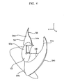
Fig. 4 is a partially broken-away perspective view of the axial-flow fan in accordance with the present invention; -
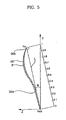
Fig. 5 is a cross-sectional view of a blade of the axial-flow fan in accordance with the present invention; -
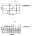
Fig. 6 is a graph showing a variation in an amount of airflow relative to a variation in the number of rotations of the conventional axial-flow fan and the axial-flow fan of the present invention; -
Fig. 7 is a graph showing a variation in power consumption relative to a variation in the number of rotations of the conventional axial-flow fan and the axial-flow fan of the present invention; -
Fig. 8 is a graph showing a variation in noise generation relative to a variation in the number of rotations of the conventional axial-flow fan and the axial-flow fan of the present invention; and -
Fig. 9 is a graph showing a variation in noise generation relative to a variation in frequency of the conventional axial-flow fan and the axial-flow fan of the present invention. - Now, a preferred embodiment of the present invention will be described in detail with reference to the annexed drawings.
- As shown in
Figs. 3 to 5 , an axial-flow fan of the present invention comprises ahub 52, a plurality ofblades 54, andprotuberances 56. Eachblade 54 is formed with one of theprotuberances 56. Thehub 52 is formed as a cylinder with the uniform diameter at afront side 52a and a rear side 52b, and guides air to centrifugally flow along the circumference of thehub 52. A rotary shaft of a motor is fit into the center of thehub 52. Theblades 54 are positioned on the outer circumference of thehub 52 and circumferentially spaced from each other by a designated interval so as to allow air to flow in the centrifugal direction. Theprotuberance 56 is formed on a designated part of each of theblades 54 so as to suppress a vortex of air flowing along theblades 54. - Based on the rotational direction of the fan, a front edge of the
blade 54 is referred to as a leadingedge 54a, and a rear edge of theblade 54 is referred to as atrailing edge 54b. A circumferential ridge obtained by interconnecting the tips of the leadingedge 54a and thetrailing edge 54b is referred to as ablade tip 54c. - The
blade tip 54c from the leadingedge 54a to thetrailing edge 54b has a predetermined curvature so that the leadingedge 54a is located on thefront side 52a of thehub 52 and thetrailing edge 54b is located on the rear side 52b of thehub 52. - Accordingly, when the axial-flow fan is rotated, air is introduced into the fan via the leading
edge 54a, flows along theblade 54, and then is centrifugally discharged from the fan via the front side of theblade 54. - Here, the front side of the
blade 54 to which high pressure of the introduced air is applied is referred to as apositive pressure side 54d, and the rear side of theblade 54 is referred to as anegative pressure side 54e. - The above-described
blade 54 has a designated rake angle (θ) . - The rake angle (θ) of the
blade 54 is an angle at which theblade 54 is tilted toward the rear side 52b of thehub 52. More specifically, the rake angle (θ) of theblade 54 is an angle between a Y-axis passing through the center of thehub 52 and a cross-section of theblade 54 taken along a line obtained by connecting ablade hub 54f and theblade tip 54c. - Here, the line obtained by connecting the
blade hub 54f and theblade tip 54c is referred to as a rake base line (L). - The
protuberance 56 is curved so as to be protruded from theblade tip 54c toward thepositive pressure side 54d. As shown inFig. 5 , in case that the distance from theblade hub 54f to theblade tip 54c is predetermined as "1", theprotuberance 56 is located throughout the section from the position of "0.3" to the position of "1". - The
protuberance 56 includes afront portion 56a and arear portion 56b. Theprotuberance 56 is centered on the peak (P) of theprotuberance 56, i.e., the most protruding portion of theprotuberance 56, such that thefront portion 56a is located close to theblade hub 54f and tilted upward in the radial direction of theblade 54 toward on the peak (P) of theprotuberance 56, and therear portion 56b is located close to theblade tip 54c and tilted downward in the radial direction of theblade 54 from the peak (P) of theprotuberance 56. - Here, the peak (P) is positioned closer to the
blade tip 54c than to theblade hub 54f. That is, the peak (P) is located between the position of "0.7" and the position of "0.8" of the distance from theblade hub 54f to theblade tip 54c, and has from the rake base line (L) a height of approximately 5∼10% of the distance between theblade hub 54f and theblade tip 54c. - The
rear portion 56b of theprotuberance 56 is formed throughout a radial distance shorter than that of thefront portion 56a connected to therear portion 56b. Accordingly, therear portion 56b has a steeper degree of slope than that of thefront portion 56a, thereby allowing air passing through the peak (P) along theblade 54 to effectively flow at theblade tip 54c. - A leading edge 56L of the
protuberance 56 is located at the position of "0.3" of the distance from theblade hub 54f to theblade tip 54c, and a trailing edge 56T of theprotuberance 56 is located at theblade tip 54c. The leading and trailing edges 56L and 56T of theprotuberance 56 are positioned on the rake base line (L). - On the other hand, the
protuberance 56 may located at a part of the section from the position of "0.3" to the position of "1" of the distance from theblade hub 54f and theblade tip 54c. - The curve of the
protuberance 56 is expressed by a secondary function or an (n)' th function (n= a natural number) so that the cross-section of theprotuberance 56 taken along the line connecting theblade hub 54f and theblade tip 54c is convex-shaped when viewed from thepositive pressure side 54d. - Hereinafter, the operation of the above-described axial-flow fan of the present invention is described.
- First, when the motor is driven, the axial-flow fan fixed to the rotary shaft of the motor is rotated. Air is introduced into the axial-flow fan via the
front side 52a of thehub 52, and then centrifugally discharged from the axial-flow fan via the rear side 52b of thehub 52. Here, the air circumferentially flows from the leadingedges 54a of theblades 54 to the trailingedges 54b of theblades 54, and simultaneously, radially flows from theblade hubs 54f to theblade tips 54c of theblades 54. - The introduced air is divided into two portions by the
leading edge 54a of theblade 54, and the divided two portions of the air are respectively fed to thepositive pressure side 54d and thenegative pressure side 54e of the blade in the circumferential direction of the blade. High pressure of the air is applied to thepositive pressure side 54d, and low pressure of the air is applied to thenegative pressure side 54e. - When the axial-flow fan is rotated, the air discharged from the
blades 54 by means of the centrifugal force flows along the radial direction of thepositive pressure side 54d and is guided by theprotuberance 56 on thepositive pressure side 54d. - More specifically, the air flowing between the
blade hub 54f and the peak (P) of theprotuberance 56 is first introduced along the front end of theleading edge 54a, and then discharged from the front end the trailingedge 54b along thefront portion 56a of theprotuberance 56 of thepositive pressure side 54d and simultaneously flows along thefront portion 56a of theprotuberance 56 in the radial direction of theblade 54 by the centrifugal force. Since thefront portion 56a of theprotuberance 56 is tilted upward in the radial direction of theblade 54, the amount of airflow blowing toward theblade tip 54c along thepositive pressure side 54d is reduced. Accordingly, the pressure of airflow on thepositive pressure side 54d at theblade tip 54c is lowered. - On the other hand, the air flowing between the peak (P) of the
protuberance 56 and theblade tip 54c is first introduced along the rear end of theleading edge 54a, and then discharged from the rear end of the trailingedge 54b along therear portion 56b of theprotuberance 56 of thepositive pressure side 54d and simultaneously flows along therear portion 56b of theprotuberance 56 in the radial direction of theblade 54 by the centrifugal force. Since therear portion 56b of theprotuberance 56 is tilted downward in the radial direction of the blade, the air effectively flows between thepositive pressure side 54d and thenegative pressure side 54e at theblade tip 54c along therear portion 56b of theprotuberance 56. - As a consequence, it is possible to reduce the amount of airflow blowing from the
positive pressure side 54d to theblade tip 54c and to allow the air to effectively flow between thepositive pressure side 54d and thenegative pressure side 54e at theblade tip 54c, thereby preventing the occurrence of a vortex stream caused by the difference of pressure between thepositive pressure side 54d and thenegative pressure side 54e, and reducing noise generated by the BVI when theblade 54 collides with the vortex stream of theearlier blade 54. - Further, the pressure of an airflow applied to the
positive pressure side 54d at theblade tip 54c is relatively lowered, and the restoration to the static pressure of air flowing from thepositive pressure side 54d to thenegative pressure side 54e is slowly performed, thereby reducing noise caused by the collision of the air with the peripheral structures. - With reference to
Figs. 6 to 8 , the axial-flow fan of the present invention comprising theprotuberances 56 formed at designated positions of theblades 54 has the same performance as that of the conventional axial-flow fan in terms of the amount of airflow and the power consumption relative to the number of rotations of the axial-flow fan. On the other hand, compared to the conventional axial-flow fan, the axial-flow fan of the present invention generates reduced noise relative to the number of rotations of the axial-flow fan. - With reference to
Fig. 9 , compared to the conventional axial-flow fan, the axial-flow fan of the present invention generates reduced isolated noise caused by the collision of the vortex occurring at theblade tip 54c with peripheral structures, relative to a variation in frequency. - That is, compared to the conventional axial-flow fan, the axial-flow fan of the present invention having the above-described anti-noise structure improves the noise reduction ratio.
- As apparent from the above description, the axial-flow fan of the present invention has several advantages, as follows.
- First, since the protuberances formed on the positive pressure sides of the blades prevent air introduced at the front ends of the leading edges from flowing toward the blade tips, the axial-flow fan of the present invention reduces the amount and the pressure of airflow flowing along the positive pressure sides at the blade tips, thereby reducing the difference of pressure between the positive pressure sides and the negative pressure sides, diminishing the occurrence of a vortex stream and the noise generated thereby.
- Second, since the protuberances formed on the positive pressure sides of the blades allow air introduced at the rear ends of the leading edges to effectively flow toward the blade tips, the axial-flow fan of the present invention lowers the pressure of airflow applied on the positive pressure sides at the blade tips, thereby slowing down the restoration to the static pressure of air flowing from the positive pressure sides to the negative pressure sides and reducing noise caused by the collision of the air with the peripheral structures.
- Although the preferred embodiments of the present invention have been disclosed for illustrative purposes, those skilled in the art will appreciate that various modifications, additions and substitutions are possible, if without departing from the scope of the invention as disclosed in the accompanying claims.
Claims (9)
- An axial-flow fan comprising a hub and a plurality of blades (54) located on an outer circumference of the hub (52) so as to axially blow air,
wherein each blade (54) includes a positive pressure side to which high pressure of the air is applied, a negative pressure side to which low pressure of the air is applied, and a protuberance (56) formed on the positive pressure side, such that a front
portion (56a) of the protuberance (56) located close to the blade hub (54f) is tilted upward in the radial direction of the blade (54) toward the most protruding peak (P) of the protuberance (56), a rear portion (56b) of the protuberance (56) located close to the blade tip (54c) is tilted downward in the radial direction of the blade (54) from the most protruding peak (P) of the protuberance (56),
characterized in that
the rear portion (56b) of the protuberance (56) has a steeper degree of slope than that of the front portion (56a) of the protuberance (56). - The axial-flow fan as set forth in claim 1,
wherein each blade (54) has a designated rake angle. - The axial-flow fan as set forth in claim 1,
wherein the protuberance (56) is located at a part of the section from a position of "0.3" to a position of "1" of a distance from the blade hub (54f) to the blade tip (54c). - The axial-flow fan as set forth in claim 3,
wherein the protuberance (56) is located close to the blade tip (54c). - The axial-flow fan as set forth in claim 1,
wherein the protuberance (56) is located throughout the section from a position of "0.3" to a position of "1" of a distance from the blade hub (54f) to the blade tip (54c). - The axial-flow fan as set forth in claim 3 or 5,
wherein the protuberance (56) is formed on the positive pressure side so as to have a convex-shaped structure when viewed from the positive pressure side. - The axial-flow fan as set forth in claim 1,
wherein the peak (P) of the protuberance (56) is positioned close to the blade tip (54c). - The axial-flow fan as set forth in claim 7,
wherein the peak (P) of the protuberance (56) is located between a position of "0.7" and a position of "0.8" of the distance from the blade hub (54f) to the blade tip (54c). - The axial-flow fan as set forth in claim 1,
wherein leading and trailing edges (54a, 54b) of the protuberance (56) are each located on a line obtained by connecting the blade hub (54f) and the blade tip (54c).
Applications Claiming Priority (2)
| Application Number | Priority Date | Filing Date | Title |
|---|---|---|---|
| KR10-2002-0071993A KR100484824B1 (en) | 2002-11-19 | 2002-11-19 | An axial flow fan |
| KR2002071993 | 2002-11-19 |
Publications (3)
| Publication Number | Publication Date |
|---|---|
| EP1422425A2 EP1422425A2 (en) | 2004-05-26 |
| EP1422425A3 EP1422425A3 (en) | 2005-01-19 |
| EP1422425B1 true EP1422425B1 (en) | 2008-12-03 |
Family
ID=32226319
Family Applications (1)
| Application Number | Title | Priority Date | Filing Date |
|---|---|---|---|
| EP03016732A Expired - Lifetime EP1422425B1 (en) | 2002-11-19 | 2003-07-22 | Axial-flow fan |
Country Status (4)
| Country | Link |
|---|---|
| EP (1) | EP1422425B1 (en) |
| JP (1) | JP2004169682A (en) |
| KR (1) | KR100484824B1 (en) |
| ES (1) | ES2316676T3 (en) |
Families Citing this family (5)
| Publication number | Priority date | Publication date | Assignee | Title |
|---|---|---|---|---|
| KR100547328B1 (en) * | 2003-09-05 | 2006-01-26 | 엘지전자 주식회사 | Axial flow fan of air conditioner outdoor unit |
| EP2212562B2 (en) * | 2007-10-25 | 2017-05-03 | LG Electronics Inc. | Fan |
| JP5425678B2 (en) * | 2010-03-24 | 2014-02-26 | 三洋電機株式会社 | Axial fan |
| KR20170032791A (en) | 2015-09-15 | 2017-03-23 | 김서연 | Lawn chair |
| JP6428833B2 (en) * | 2017-04-14 | 2018-11-28 | ダイキン工業株式会社 | Propeller fan |
Family Cites Families (13)
| Publication number | Priority date | Publication date | Assignee | Title |
|---|---|---|---|---|
| GB401625A (en) * | 1932-07-30 | 1933-11-16 | British Thomson Houston Co Ltd | Improvements in and relating to rotary fans |
| JP2809442B2 (en) * | 1989-08-30 | 1998-10-08 | カルソニック株式会社 | Cooling fan for automotive heat exchanger |
| US4930990A (en) * | 1989-09-15 | 1990-06-05 | Siemens-Bendix Automotive Electronics Limited | Quiet clutch fan blade |
| JP2765219B2 (en) * | 1990-11-06 | 1998-06-11 | 株式会社デンソー | Blower fan |
| JP3203994B2 (en) * | 1994-10-31 | 2001-09-04 | 三菱電機株式会社 | Axial blower |
| JP3346179B2 (en) * | 1996-08-02 | 2002-11-18 | ダイキン工業株式会社 | Impeller for blower |
| JPH1144432A (en) * | 1997-07-24 | 1999-02-16 | Hitachi Ltd | Air conditioner |
| KR19990020857A (en) * | 1997-08-30 | 1999-03-25 | 양재신 | Low noise cooling fan with good ventilation |
| JP3204208B2 (en) * | 1998-04-14 | 2001-09-04 | 松下電器産業株式会社 | Mixed-flow blower impeller |
| IT1303113B1 (en) * | 1998-10-08 | 2000-10-30 | Gate Spa | AXIAL FAN, IN PARTICULAR FOR THE COOLING OF A HEAT EXCHANGER IN A VEHICLE. |
| US6447251B1 (en) * | 2000-04-21 | 2002-09-10 | Revcor, Inc. | Fan blade |
| KR100421884B1 (en) * | 2001-02-13 | 2004-03-09 | 엘지전자 주식회사 | axial fan |
| JP2002250298A (en) * | 2001-02-23 | 2002-09-06 | Mitsubishi Heavy Ind Ltd | Propeller fan |
-
2002
- 2002-11-19 KR KR10-2002-0071993A patent/KR100484824B1/en not_active Expired - Fee Related
-
2003
- 2003-07-08 JP JP2003193719A patent/JP2004169682A/en active Pending
- 2003-07-22 ES ES03016732T patent/ES2316676T3/en not_active Expired - Lifetime
- 2003-07-22 EP EP03016732A patent/EP1422425B1/en not_active Expired - Lifetime
Also Published As
| Publication number | Publication date |
|---|---|
| EP1422425A3 (en) | 2005-01-19 |
| KR100484824B1 (en) | 2005-04-22 |
| JP2004169682A (en) | 2004-06-17 |
| EP1422425A2 (en) | 2004-05-26 |
| KR20040043623A (en) | 2004-05-24 |
| ES2316676T3 (en) | 2009-04-16 |
Similar Documents
| Publication | Publication Date | Title |
|---|---|---|
| US6027307A (en) | Fan and shroud assembly adopting the fan | |
| EP1208303B1 (en) | Cooling fan | |
| EP1862675B1 (en) | Axial fan assembly | |
| CN1616832B (en) | Propeller fan and outdoor unit for air conditioner using same | |
| US6039532A (en) | Blower fan blade passage rate noise control scheme | |
| EP1624193A1 (en) | Multi-vane centrifugal blower | |
| JPS63124900A (en) | Axial blower | |
| US8167562B2 (en) | Centrifugal fan and blower having the same | |
| US6024537A (en) | Axial flow fan | |
| AU2003207098A1 (en) | Fan | |
| JP5145188B2 (en) | Multiblade centrifugal fan and air conditioner using the same | |
| JP3469857B2 (en) | Axial flow fan for cooling air circulation | |
| JP4014887B2 (en) | Centrifugal fan and cooking device equipped with the centrifugal fan | |
| US20030044280A1 (en) | Turbo fan | |
| WO1991004419A1 (en) | Quiet clutch fan blade | |
| JP3677214B2 (en) | Axial fan | |
| EP1422425B1 (en) | Axial-flow fan | |
| KR102724274B1 (en) | Cooling fan | |
| EP1411248B1 (en) | Impeller for centrifugal fan and centrifugal fan equipped with the same | |
| EP1326482A2 (en) | Cooling fan for microwave oven | |
| KR100347914B1 (en) | Turbo fan | |
| KR100422704B1 (en) | Axial fan with Auxiliary impeller | |
| KR100416779B1 (en) | A turbo fan | |
| JPH07301198A (en) | Blower | |
| KR100416777B1 (en) | Turbo fan |
Legal Events
| Date | Code | Title | Description |
|---|---|---|---|
| PUAI | Public reference made under article 153(3) epc to a published international application that has entered the european phase |
Free format text: ORIGINAL CODE: 0009012 |
|
| 17P | Request for examination filed |
Effective date: 20030722 |
|
| AK | Designated contracting states |
Kind code of ref document: A2 Designated state(s): AT BE BG CH CY CZ DE DK EE ES FI FR GB GR HU IE IT LI LU MC NL PT RO SE SI SK TR |
|
| AX | Request for extension of the european patent |
Extension state: AL LT LV MK |
|
| PUAL | Search report despatched |
Free format text: ORIGINAL CODE: 0009013 |
|
| AK | Designated contracting states |
Kind code of ref document: A3 Designated state(s): AT BE BG CH CY CZ DE DK EE ES FI FR GB GR HU IE IT LI LU MC NL PT RO SE SI SK TR |
|
| AX | Request for extension of the european patent |
Extension state: AL LT LV MK |
|
| AKX | Designation fees paid |
Designated state(s): ES FR IT |
|
| REG | Reference to a national code |
Ref country code: DE Ref legal event code: 8566 |
|
| 17Q | First examination report despatched |
Effective date: 20060620 |
|
| RIN1 | Information on inventor provided before grant (corrected) |
Inventor name: CHIN, SIM WON Inventor name: CHUNG, MOON KEE |
|
| GRAP | Despatch of communication of intention to grant a patent |
Free format text: ORIGINAL CODE: EPIDOSNIGR1 |
|
| GRAS | Grant fee paid |
Free format text: ORIGINAL CODE: EPIDOSNIGR3 |
|
| GRAA | (expected) grant |
Free format text: ORIGINAL CODE: 0009210 |
|
| AK | Designated contracting states |
Kind code of ref document: B1 Designated state(s): ES FR IT |
|
| REG | Reference to a national code |
Ref country code: ES Ref legal event code: FG2A Ref document number: 2316676 Country of ref document: ES Kind code of ref document: T3 |
|
| PLBE | No opposition filed within time limit |
Free format text: ORIGINAL CODE: 0009261 |
|
| STAA | Information on the status of an ep patent application or granted ep patent |
Free format text: STATUS: NO OPPOSITION FILED WITHIN TIME LIMIT |
|
| 26N | No opposition filed |
Effective date: 20090904 |
|
| REG | Reference to a national code |
Ref country code: FR Ref legal event code: PLFP Year of fee payment: 14 |
|
| REG | Reference to a national code |
Ref country code: FR Ref legal event code: PLFP Year of fee payment: 15 |
|
| PGFP | Annual fee paid to national office [announced via postgrant information from national office to epo] |
Ref country code: FR Payment date: 20170608 Year of fee payment: 15 |
|
| PGFP | Annual fee paid to national office [announced via postgrant information from national office to epo] |
Ref country code: IT Payment date: 20170712 Year of fee payment: 15 Ref country code: ES Payment date: 20170814 Year of fee payment: 15 |
|
| PG25 | Lapsed in a contracting state [announced via postgrant information from national office to epo] |
Ref country code: FR Free format text: LAPSE BECAUSE OF NON-PAYMENT OF DUE FEES Effective date: 20180731 |
|
| PG25 | Lapsed in a contracting state [announced via postgrant information from national office to epo] |
Ref country code: IT Free format text: LAPSE BECAUSE OF NON-PAYMENT OF DUE FEES Effective date: 20180722 |
|
| REG | Reference to a national code |
Ref country code: ES Ref legal event code: FD2A Effective date: 20190917 |
|
| PG25 | Lapsed in a contracting state [announced via postgrant information from national office to epo] |
Ref country code: ES Free format text: LAPSE BECAUSE OF NON-PAYMENT OF DUE FEES Effective date: 20180723 |