EP1422380B1 - Procédé et système pour la réparation automatisée des aubes endommagées de compresseur ou turbine - Google Patents
Procédé et système pour la réparation automatisée des aubes endommagées de compresseur ou turbine Download PDFInfo
- Publication number
- EP1422380B1 EP1422380B1 EP03257296A EP03257296A EP1422380B1 EP 1422380 B1 EP1422380 B1 EP 1422380B1 EP 03257296 A EP03257296 A EP 03257296A EP 03257296 A EP03257296 A EP 03257296A EP 1422380 B1 EP1422380 B1 EP 1422380B1
- Authority
- EP
- European Patent Office
- Prior art keywords
- blade
- damage
- repair
- geometry
- damaged
- Prior art date
- Legal status (The legal status is an assumption and is not a legal conclusion. Google has not performed a legal analysis and makes no representation as to the accuracy of the status listed.)
- Expired - Fee Related
Links
- 230000008439 repair process Effects 0.000 title claims description 95
- 238000000034 method Methods 0.000 title claims description 15
- 238000013461 design Methods 0.000 title description 2
- 238000010586 diagram Methods 0.000 claims description 14
- 238000005259 measurement Methods 0.000 claims description 12
- 230000002452 interceptive effect Effects 0.000 claims description 3
- 230000000694 effects Effects 0.000 claims description 2
- 238000007689 inspection Methods 0.000 description 3
- 238000011156 evaluation Methods 0.000 description 2
- 238000003754 machining Methods 0.000 description 2
- 238000004891 communication Methods 0.000 description 1
- 150000001875 compounds Chemical class 0.000 description 1
- 238000010276 construction Methods 0.000 description 1
- 238000007796 conventional method Methods 0.000 description 1
- 238000003745 diagnosis Methods 0.000 description 1
- 238000013507 mapping Methods 0.000 description 1
- 239000000203 mixture Substances 0.000 description 1
- 238000012552 review Methods 0.000 description 1
Images


Classifications
-
- B—PERFORMING OPERATIONS; TRANSPORTING
- B23—MACHINE TOOLS; METAL-WORKING NOT OTHERWISE PROVIDED FOR
- B23P—METAL-WORKING NOT OTHERWISE PROVIDED FOR; COMBINED OPERATIONS; UNIVERSAL MACHINE TOOLS
- B23P6/00—Restoring or reconditioning objects
- B23P6/04—Repairing fractures or cracked metal parts or products, e.g. castings
-
- B—PERFORMING OPERATIONS; TRANSPORTING
- B23—MACHINE TOOLS; METAL-WORKING NOT OTHERWISE PROVIDED FOR
- B23P—METAL-WORKING NOT OTHERWISE PROVIDED FOR; COMBINED OPERATIONS; UNIVERSAL MACHINE TOOLS
- B23P6/00—Restoring or reconditioning objects
- B23P6/002—Repairing turbine components, e.g. moving or stationary blades, rotors
-
- F—MECHANICAL ENGINEERING; LIGHTING; HEATING; WEAPONS; BLASTING
- F01—MACHINES OR ENGINES IN GENERAL; ENGINE PLANTS IN GENERAL; STEAM ENGINES
- F01D—NON-POSITIVE DISPLACEMENT MACHINES OR ENGINES, e.g. STEAM TURBINES
- F01D5/00—Blades; Blade-carrying members; Heating, heat-insulating, cooling or antivibration means on the blades or the members
- F01D5/005—Repairing methods or devices
-
- Y—GENERAL TAGGING OF NEW TECHNOLOGICAL DEVELOPMENTS; GENERAL TAGGING OF CROSS-SECTIONAL TECHNOLOGIES SPANNING OVER SEVERAL SECTIONS OF THE IPC; TECHNICAL SUBJECTS COVERED BY FORMER USPC CROSS-REFERENCE ART COLLECTIONS [XRACs] AND DIGESTS
- Y10—TECHNICAL SUBJECTS COVERED BY FORMER USPC
- Y10T—TECHNICAL SUBJECTS COVERED BY FORMER US CLASSIFICATION
- Y10T29/00—Metal working
- Y10T29/49—Method of mechanical manufacture
- Y10T29/49718—Repairing
- Y10T29/49721—Repairing with disassembling
- Y10T29/4973—Replacing of defective part
Definitions
- Blades in an axial turbine or compressor can be damaged, such that the blade is chipped, bent or otherwise deformed.
- a deformed blade may perform poorly and can further damage the compressor or turbine. Detecting a damaged blade and correctly repairing the blade promptly may avoid additional machine failure and damage.
- a blade repair technician is usually experienced with blade repairs or may engage in extensive communication with an engineer familiar with the construction and operation of the machine or machine part to be repaired. Oftentimes, the length of time to detect, diagnose, solve and repair a damaged blade consumes many days or weeks, resulting in an inordinate and expensive machine downtime.
- Common errors or miscommunications that compound the blade repair efforts include misinterpretation or misapplication of the blade schematics, drawings and such, or of the blade repair directions provided in manuals for the blades. Such misinterpretation and misapplication can result in unacceptable or unsuccessful repair, and lead to subsequent damage and delay. Accordingly, there is a long felt need for a fast and reliable system to assist blade repair technicians, and to provide instructions regarding the repair of damaged blades.
- One system shown in US 2002/0128790 , has been devised to provide an automatic assessment of dimension and condition of parts. Another type of automatic system particularly for server and multiple client functions has been shown in WO 01/35248
- An automated system has been developed for use in categorizing and evaluating damaged blades of a turbine or compressor, and generating blade repair instructions.
- the system may be implemented in software that automatically generates diagnostic, design and repair information such as damage assessment, blade geometry, performance impact, evaluation and instructions for repairing damaged compressor or turbine blades.
- a method for evaluating a damaged blade in a compressor or turbine using a computer system accessing a database of blade repair information includes: selecting a blade damage geometry category corresponding to the damage of the blade from a plurality of blade damage geometry categories; measuring the blade damage, and generating a repair geometry for said blade damage based on the blade damage measurements and the selected blade damage geometry category, displaying a diagram of the blade geometry and generating instructions regarding blade repair dimensions, wherein said repair geometry is generated by said computer system
- a system for evaluating a damaged blade in a compressor or turbine having a computer system accessing a database of blade repair information; an interactive damaged blade disposition form generated by said computer system, where the disposition form includes data fields for entering blade identification information, damage type and blade damage dimensions; and a blade repair geometry form generated by said computer system including a repair geometry diagram and repair geometry dimensions generated by said computer system based on the blade damage type and blade damage dimensions entered through said disposition form and instructions regarding the blade repair dimensions.
- An automated computer software system has been developed to allow an engineer or field technician to categorize the damage on a blade, evaluate whether the blade needs to be or should be repaired, and generate a repair geometry for a damaged turbine or compressor blade. Automating the evaluation and repair of damaged turbine and compressor blades is expected to reduce the period needed to diagnose and repair damaged blades from several days to a few hours.
- the software package assists in the diagnosis of damaged blades by assisting an engineer or technician to determine whether the damage blade deviates from acceptable dimensions and, if so, whether the blade is repairable.
- the software package may be implemented on a spread sheet software program that may be executed on a conventional computer system.
- FIGURE 1 shows an exemplary damaged blade 10 of an axial compressor or turbine.
- the blade has a missing tip point 12 at the leading edge (LE) 14 of the blade.
- the missing tip point broke off from the blade tip 18.
- the missing tip point may affect the performance of the compressor or turbine.
- the jagged edge 16 of the broken tip point may promote fatigue cracks in the blade and could cause the blade to be further damaged or fail.
- the missing tip point is one example of several types of damage that occurs to the geometry of blades. Other types of blade damage includes bent blade tips, cracks in the blade, and dents and nicks in the leading edge of the blade.
- Damaged blades are generally detected when a turbine or compressor is stopped and opened for inspection. During inspection, each row of blades of the turbine and compressor are visually reviewed to determine whether the geometry of any blade has been damaged. When faced with a damaged blade, a technician generally determines whether the blade needs repair and whether it can be repaired.
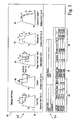
- FIGURE 2 is a high-level flow chart of the steps performed by the automated blade repair system 50.
- the automated damaged blade repair system 50 assists a technician to determine whether a damage blade requires repair and whether the blade is repairable. If the blade is repairable, the system also generates a proposed blade repair geometry to guide the technician when repairing the blade.
- the types of repairs suggested by the proposed blade geometry are generally performed on the blade while mounted in a compressor or turbine.
- the suggested repair generally involves a technician machining the damaged portion of the blade to cut away cracks and other damaged regions of the blade, smooth the edges of the damaged portion to blend the edges into the remaining portion of the blade, and to round or straighten the edges of the damaged portion of the blade.
- the automated damaged blade repair system 50 generates a suggested repair geometry to guide the technician when machining the damaged blade.
- the automated damaged blade repair system 50 may be executed on a conventional computer system that may have conventional processors and storage devices to operate the software package, and that accesses databases 52 having information regarding the blades of gas turbine with the damaged blade, blade damage assessment information and historical information regarding repairs made (or not made) to blades.
- the database may include information regarding previously damaged blades including the location and damage geometry of the blade, the repair geometry made to the blade, and the impact on performance of the compressor or turbine due to the damaged blade and the repaired blade.
- This database of previously damaged blade may also include information regarding damaged blades that were not repairable, and the types and geometry of the damage which were deemed to be unrepairable.
- the system 50 enables operators to quickly compare a damaged blade to repaired blades of the same type.
- the system 50 also compare the extend of damage done to a blade to established limits to determine whether the damaged blade is repairable on-site and to generate a proposed repair geometry.
- the databases accessible by the software package may also include blade geometry standards, for a wide variety of blades.
- a damaged blade is detected, step 54, usually by a technician inspecting the blades of a compressor or turbine.
- the inspection is performed while the compressor or turbine is at a stand still.
- the machine e.g. a gas turbine, with the compressor and turbine is off-line and is not generating power.
- the machine e.g. a gas turbine
- the compressor and turbine is off-line and is not generating power.
- the technician uses the automated blade repair system 50 to determine whether the blade may be repaired on-site and to generate a proposed repair geometry.
- the repair system 50 may be a software program adapted to run on a conventional spread sheet program on a laptop computer readily available to the technician.
- the automated blade repair system 50 provides the technician with a tool to access database records regarding similar damage to blades as the technician is facing with the current damaged blade.
- the system 50 also guides the technician through a process of analyzing the damaged blade.
- FIGURE 3 is an exemplary damaged blade disposition electronic form 80 that prompts the technician to enter certain information regarding the damaged blade.
- the form includes identifying database fields 82, which are linked to the corresponding databases 52, for entering information to identify the machine serial number, customer name, machine size and other identifying information useful in determining the blades that have been damaged.
- the information needed to identify the blade and its associated machine is entered into the form via the database fields 82.
- the blade technician enters the blade part number (or numbers if multiple blades are damaged) into a database fields 83 for the blade identifying information.
- the blade repair system 50 retrieves from the databases 52 the desired blade geometry as well as information regarding acceptable deviations from the desired blade geometry, repairable damage to the blade and performance impact to the gas turbine (or other device having the affected compressor or turbine).
- the entered information may be used to generate an appropriate electronic form that is specific to blades from the identified machine or to display exemplary damaged blade diagrams that correspond to the actual blade that has been damaged.
- the exemplary form also includes damaged blade diagrams 84 showing various types of blade damage. These diagram assist the technician to categorize the damage on the blade, in step 58.
- the diagrams may be specific to certain types of blades, e.g., compressor or turbine blade, and the appropriate diagram 84 and form 80 may be generated from database information after the technician has identified the machine that has the damaged blade.
- the diagrams may show blade damage types of: bent blade tip 86; crack in blade 88; dent, nick or tear in the blade 90, missing blade tip point 92 and leading edge nicks in the blade 94.
- a technician selects the proper blade damage category, and enters or selects that category into damage type database field 96 in the form 80 in the form row that has been setup for entering information regarding the damaged blade.
- the damaged blade diagrams 84 also indicate the measurements to be made of the damage to the blade, for each type of blade damage. Generally, a measurement is made of the distance (Y) from the blade tip 18 to the lower end of the damaged portion of the blade, in step 60. In addition, measurements are made of the extent of the damage to the blade, in step 62. For example, the width (X) of the damaged portion may be measured of a blade with a missing tip. The measurements of the damaged portions of the blade are recorded in the database, in step 64, by entering the measurements into the database fields 98 for damage measurements.
- the blade repair system 50 compares the geometry of the damage blade to the blade geometry limits established for the blade, in step 66.
- the database of 52 includes information regarding blades and the geometry limits on permissible repairs that may be made by grinding the blade.
- the blade geometry limits may include ranges of the desired blade dimensions acceptable for an operating blade, and the types and ranges of blade damage dimensions that may be repaired by grinding the blade on the compressor or turbine.
- the system 50 determines if the damaged portion of the blade is within repairable limits, in step 68.
- the measurements of the damaged portions of the blade are compared to the repairable limits to determine if the blade may be repaired while in place on the compressor turbine. If the damaged portion of the blade exceeds the repairable limits, then the system 50 may advise the technician to extract the damaged blade from the compressor or turbine, and replace the blade or arrange for a customize repair of the blade, in step 70. Extracting a compressor blade involves unstacking the rotor disks which generally involves a major expense and time delay for repairing the compressor. Further, a customized repair of a blade may need to be performed by the blade manufacturer. Accordingly, it is preferable to repair the blade on the compressor rather than extracting the blade for repair.
- the system If the damage to the blade is within acceptable repair limits, then the system generates a proposed repair geometry for the blade, in step 72.
- the software analyzes a number of blade geometries by stage, location of the damage on the blade, and product type. The software compares the damage geometry of the damaged blade to the engineering limits and repair geometry of selected other repaired (or unrepairable) blades that are comparable to the damaged blade. Assuming that the damage is repairable, the software determines an optimum repair or blend geometry by mapping an area of the blade beyond the damage region that is to be cut away from the blade or to be blended with the remaining portion of the blade. The system may also determine whether the repair geometry should be, for example, triangular in shape (see Type I tip crop) or rectangular in shape (see Type II tip crop) depending predetermined criteria for blade repair and the dimension of the damaged area of the blade.
- the map of the repair geometry may be determined by adding a predetermined distance, e.g., 3.18 mm (0.125 inches), to the damaged region to create a geometry of a repair region that removes the blade damage.
- a predetermined distance e.g. 3.18 mm (0.125 inches
- the shape and some dimensions of the repair geometry e.g., corner radius, may be based on established repair outlines stored in the database as corresponding to the damaged blade and type of blade damage.
- the proposed repair geometry is displayed on an electronic repair geometry form 100 generated by the system, such as is shown in FIGURE 4 .
- the repair geometry form includes repair diagrams showing the shape of the repair to be made to the blade.
- the proposed repair includes instructions 102, such as the dimensions of the repair, radial dimension of corners in the repair, and other information that may assist in grinding a repair to the blade. These instructions may be pulled from a database of repair instructions for the type of blade repair corresponding to the damaged blade.
- algorithms executed by the system 50 may convert the measured dimensions of the damaged region of the blade into repair dimensions. The instructions and algorithms may be unique to each blade type and machine, and can be developed by the blade manufacturer.
- the system 50 makes the instructions and algorithms readily accessible to technicians repairing blades on site of the compressor or turbine.
- the software system 50 generates the appropriate repair geometry based on the type of blade damage and the dimensions of the damage.
- the repair geometry along with a repair illustration and instruction is created on screen and in a printable format. The technician can then use the results as an engineering disposition and begin repairing the hardware.
- the software system 50 may also sum the total amount of blades and blade area to be repaired or removed to provide an estimate of the impact on the performance of the gas turbine (or compressor) with the repaired components, in step 74.
- the performance impact is predicted based on data regarding the performance effects that previous blade repairs have had on a compressor or turbine.
- the performance impact of blade repairs is stored in the database and is available to the system 50. Should the performance impact exceed a predetermined limit, the user is directed to contact engineering for review and approval.
- the system 50 determines if the damaged blade has dimensions within the acceptable operating ranges, in step 76. If the damage is within the acceptable limits, then no repair is needed to the blade. If the damage exceeds these limits, then the system determines if the damage is repairable, in the manner discussed above.
Claims (10)
- Procédé (50) d'évaluation d'une aube endommagée dans un compresseur ou une turbine à l'aide d'un système informatique ayant accès à une base de données (52) d'informations de réparation d'aube, ledit procédé consistant à :a. sélectionner une catégorie (58) géométrique de dommage d'aube correspondant au dommage de l'aube à partir d'une pluralité de catégories géométriques de dommage d'aube stockées dans ladite base de données ; etb. mesurer le dommage (60, 62) de l'aube, caractérisé par le fait dec. générer une géométrie (72) de réparation pour ladite aube endommagée en fonction des mesures de dommage de l'aube et de la catégorie géométrique de dommage d'aube sélectionnée, afficher un diagramme de la géométrie de réparation de l'aube ainsi que des instructions (102) de génération concernant les dimensions de réparation de l'aube, dans lequel ladite géométrie de réparation est générée par ledit système informatique.
- Procédé selon la revendication 1 consistant en outre à identifier l'aube endommagée (54) et à accéder à une base de données d'informations concernant l'aube identifiée.
- Procédé selon la revendication 1 dans lequel la catégorie géométrique de dommage d'aube est sélectionnée pour une pluralité de catégories comprenant une extrémité (86) d'aube recourbée, une extrémité (92) d'aube manquante, une fissure (88) dans une aube, et une bosse (90) au niveau du bord d'aube.
- Procédé selon la revendication 1 dans lequel mesurer le dommage de l'aube consiste à mesurer une distance depuis une extrémité de l'aube jusqu'au dommage (60).
- Procédé selon la revendication 1 consistant en outre à comparer (68) les mesures du dommage de l'aube à des limites d'aube réparable auxquelles on accède (66) à partir de ladite base de données et qui correspondent à ladite catégorie géométrique de dommage d'aube sélectionnée, et à générer la géométrie de réparation de l'aube après avoir déterminé que les mesures du dommage de l'aube se trouvent à l'intérieur desdites limites.
- Procédé selon la revendication 5 consistant en outre à générer une instruction (70) pour extraire l'aube endommagée après avoir déterminé que les mesures du dommage de l'aube se trouvent au delà desdites limites.
- Procédé selon la revendication 1 consistant en outre à déterminer un effet de la réparation de l'aube sur une performance du compresseur ou de la turbine (74).
- Système (50) d'évaluation d'une aube endommagée dans un compresseur ou une turbine comprenant :un système informatique ayant accès à une base de données (52) contenant les informations de réparation de l'aube ; etun formulaire (80) de disposition d'aube endommagée interactif généré par ledit système informatique, ledit formulaire de disposition comprenant des champs (82) de données permettant d'entrer des informations (83) d'identification de l'aube, le type (96) de dommage et les dimensions (98) de l'aube endommagée, caractérisé parun formulaire (100) de géométrie de réparation d'aube généré par ledit système informatique comprenant un diagramme de géométrie de réparation et des dimensions de géométrie de réparation générés par ledit système informatique en fonction du type de dommage de l'aube et des dimensions du dommage de l'aube entrées par le biais dudit formulaire (80) de disposition et des instructions (102) concernant les dimensions de réparation de l'aube.
- Système selon la revendication 8 dans lequel lesdits champs (82) de données permettant d'entrer des informations d'identification de l'aube sont électroniquement liés à une base de données d'informations concernant des aubes correspondant à l'aube endommagée.
- Système selon la revendication 8 dans lequel ledit type de dommage peut être sélectionné à partir d'une pluralité de types de dommage comprenant une extrémité (86) d'aube recourbée, une extrémité (92) d'aube manquante, une fissure (88) dans une aube, et une bosse (90) au niveau du bord d'aube.
Applications Claiming Priority (2)
| Application Number | Priority Date | Filing Date | Title |
|---|---|---|---|
| US10/301,723 US6915236B2 (en) | 2002-11-22 | 2002-11-22 | Method and system for automated repair design of damaged blades of a compressor or turbine |
| US301723 | 2002-11-22 |
Publications (3)
| Publication Number | Publication Date |
|---|---|
| EP1422380A2 EP1422380A2 (fr) | 2004-05-26 |
| EP1422380A3 EP1422380A3 (fr) | 2006-10-11 |
| EP1422380B1 true EP1422380B1 (fr) | 2009-07-01 |
Family
ID=32229906
Family Applications (1)
| Application Number | Title | Priority Date | Filing Date |
|---|---|---|---|
| EP03257296A Expired - Fee Related EP1422380B1 (fr) | 2002-11-22 | 2003-11-19 | Procédé et système pour la réparation automatisée des aubes endommagées de compresseur ou turbine |
Country Status (5)
| Country | Link |
|---|---|
| US (1) | US6915236B2 (fr) |
| EP (1) | EP1422380B1 (fr) |
| JP (1) | JP3972989B2 (fr) |
| KR (1) | KR100847939B1 (fr) |
| DE (1) | DE60328156D1 (fr) |
Cited By (1)
| Publication number | Priority date | Publication date | Assignee | Title |
|---|---|---|---|---|
| DE102015204797A1 (de) * | 2015-03-17 | 2016-09-22 | MTU Aero Engines AG | Wartung einer gebrauchten Gasturbine |
Families Citing this family (34)
| Publication number | Priority date | Publication date | Assignee | Title |
|---|---|---|---|---|
| US7698030B2 (en) * | 2003-09-24 | 2010-04-13 | Siemens Energy, Inc. | Turbine component tracking system |
| EP1655100A1 (fr) * | 2004-11-05 | 2006-05-10 | Siemens Aktiengesellschaft | Procédé d'usinage d'une pièce, et pièce |
| US20070050172A1 (en) * | 2005-09-01 | 2007-03-01 | General Electric Company | Method and apparatus for measuring throat areas of gas turbine engine nozzle assemblies |
| US7337058B1 (en) | 2007-02-12 | 2008-02-26 | Honeywell International, Inc. | Engine wear characterizing and quantifying method |
| EP1961914A1 (fr) * | 2007-02-26 | 2008-08-27 | Siemens Aktiengesellschaft | Procédé automatique pour effectuer une mesure de remise en état pour une turbine d'une centrale thermique |
| US20090068349A1 (en) * | 2007-09-12 | 2009-03-12 | Mccall Thomas | Method of repairing a turbine engine component |
| WO2009105221A2 (fr) * | 2008-02-19 | 2009-08-27 | Rolls-Royce Corporation | Système, procédé et appareil pour réparer des objets |
| GB0812478D0 (en) * | 2008-07-09 | 2008-08-13 | Rolls Royce Plc | An apparatus and a method of measuring erosion of an edge of a turbomachine aerofoil |
| DE102010055775A1 (de) * | 2010-12-23 | 2012-06-28 | Lufthansa Technik Ag | Verfahren zur Instandsetzung von Gasturbinenkomponenten |
| DE102011103003A1 (de) * | 2011-05-24 | 2012-11-29 | Lufthansa Technik Ag | Verfahren und Vorrichtung zur Rissprüfung eines Flugzeug- oder Gasturbinen-Bauteils |
| US20130180107A1 (en) * | 2012-01-15 | 2013-07-18 | Steven Charles Woods | Method for refurbishing a turbo-machine component |
| US20130311111A1 (en) * | 2012-05-15 | 2013-11-21 | Arne K. Lewis | Damage assessment system and methods of operating same |
| DE102012221782A1 (de) | 2012-11-28 | 2014-05-28 | Lufthansa Technik Ag | Verfahren und Vorrichtung zur Reparatur eines Flugzeug- und/oder Gasturbinen-Bauteils |
| US9587740B2 (en) * | 2013-04-08 | 2017-03-07 | Caterpillar Inc. | Repaired pistons and collection thereof |
| GB201503683D0 (en) | 2015-03-05 | 2015-04-22 | Rolls Royce Plc | A tool for machining an object |
| US10852217B2 (en) | 2015-09-08 | 2020-12-01 | General Electric Company | Methods and systems for determining causes of conditions in components of rotary machines |
| US10713773B2 (en) | 2015-09-08 | 2020-07-14 | General Electric Company | System and method for identifying a condition of rotary machine components |
| US20170218762A1 (en) * | 2016-02-03 | 2017-08-03 | General Electric Company | Situ Gas Turbine Prevention of Crack Growth Progression |
| US20170370220A1 (en) * | 2016-06-24 | 2017-12-28 | United Technologies Corporation | Customized blend limit for gas turbine engine airfoils |
| US20180216464A1 (en) * | 2017-01-31 | 2018-08-02 | General Electric Company | Method of repairing a blisk |
| US10268913B2 (en) * | 2017-04-03 | 2019-04-23 | General Electric Company | Equipment damage prediction system using neural networks |
| US10591288B2 (en) * | 2017-06-27 | 2020-03-17 | The Boeing Company | System and method for evaluation of used components |
| US10947849B2 (en) * | 2017-06-27 | 2021-03-16 | General Electric Company | Systems and methods for recontouring engine components |
| EP3434864B1 (fr) * | 2017-07-27 | 2020-12-16 | General Electric Company | Procédé et système de réparation d'une turbomachine |
| CN108544181B (zh) * | 2018-03-27 | 2020-05-19 | 西北工业大学 | 一种整体叶盘损伤叶片的修复方法 |
| US11434764B2 (en) * | 2018-08-13 | 2022-09-06 | Raytheon Technologies Corporation | Process for repairing turbine engine components |
| CN109623257B (zh) * | 2018-11-23 | 2020-04-03 | 东风汽车集团有限公司 | 一种后背门启闭轨迹的校正装置及方法 |
| KR102302909B1 (ko) * | 2020-03-27 | 2021-09-16 | 두산중공업 주식회사 | 적층 가공을 이용한 터빈 블레이드의 보수 방법 |
| CN113441725B (zh) | 2020-03-27 | 2023-09-22 | 斗山重工业建设有限公司 | 利用增材制造的涡轮机叶片的修复方法 |
| DE102021118371A1 (de) * | 2021-07-15 | 2023-01-19 | Lufthansa Technik Aktiengesellschaft | Verfahren zur Unterstützung einer Bearbeitung einer Beschädigung an einer Beschaufelung einer Strömungsmaschine, insbesondere eines Strahltriebwerkes, Computerprogrammprodukt sowie System |
| US11828190B2 (en) | 2021-11-18 | 2023-11-28 | General Electric Company | Airfoil joining apparatus and methods |
| US20230311252A1 (en) * | 2022-04-05 | 2023-10-05 | Raytheon Technologies Corporation | Blend approach based inspection and analysis systems and methods |
| US11860060B2 (en) | 2022-04-05 | 2024-01-02 | Rtx Corporation | Integrally bladed rotor analysis and repair systems and methods |
| EP4306769A1 (fr) * | 2022-07-13 | 2024-01-17 | Siemens Energy Global GmbH & Co. KG | Procédé de réparation de composants de moteurs à écoulement continu |
Family Cites Families (8)
| Publication number | Priority date | Publication date | Assignee | Title |
|---|---|---|---|---|
| US4422333A (en) * | 1982-04-29 | 1983-12-27 | The Franklin Institute | Method and apparatus for detecting and identifying excessively vibrating blades of a turbomachine |
| US5210704A (en) * | 1990-10-02 | 1993-05-11 | Technology International Incorporated | System for prognosis and diagnostics of failure and wearout monitoring and for prediction of life expectancy of helicopter gearboxes and other rotating equipment |
| US5686669A (en) * | 1996-02-29 | 1997-11-11 | Monitoring Technology Corporation | Apparatus and method for analyzing the condition and performance of turbomachines by processing signals representing rotor motion |
| DE19642980C1 (de) * | 1996-10-18 | 1998-08-13 | Mtu Muenchen Gmbh | Verfahren zur Instandsetzung verschlissener Schaufelspitzen von Verdichter- und Turbinenschaufel |
| US6668272B1 (en) | 1999-11-05 | 2003-12-23 | General Electric Company | Internet-based process optimization system and method |
| US6594533B2 (en) * | 2001-03-02 | 2003-07-15 | General Electric Company | System and method for performing electronic triage of a turbine part |
| US20020128790A1 (en) | 2001-03-09 | 2002-09-12 | Donald Woodmansee | System and method of automated part evaluation including inspection, disposition recommendation and refurbishment process determination |
| US6701615B2 (en) * | 2002-03-08 | 2004-03-09 | General Electric Company | Inspection and sorting system and method for part repair |
-
2002
- 2002-11-22 US US10/301,723 patent/US6915236B2/en not_active Expired - Lifetime
-
2003
- 2003-11-19 DE DE60328156T patent/DE60328156D1/de not_active Expired - Lifetime
- 2003-11-19 EP EP03257296A patent/EP1422380B1/fr not_active Expired - Fee Related
- 2003-11-21 JP JP2003391553A patent/JP3972989B2/ja not_active Expired - Fee Related
- 2003-11-21 KR KR1020030083173A patent/KR100847939B1/ko active IP Right Grant
Cited By (4)
| Publication number | Priority date | Publication date | Assignee | Title |
|---|---|---|---|---|
| DE102015204797A1 (de) * | 2015-03-17 | 2016-09-22 | MTU Aero Engines AG | Wartung einer gebrauchten Gasturbine |
| EP3082004A3 (fr) * | 2015-03-17 | 2016-11-02 | MTU Aero Engines GmbH | Entretien d'une turbine a gaz usagee |
| DE102015204797B4 (de) | 2015-03-17 | 2017-02-02 | MTU Aero Engines AG | Wartung einer gebrauchten Gasturbine |
| US10126207B2 (en) | 2015-03-17 | 2018-11-13 | MTU Aero Engines AG | Maintenance of a used gas turbine |
Also Published As
| Publication number | Publication date |
|---|---|
| EP1422380A3 (fr) | 2006-10-11 |
| JP3972989B2 (ja) | 2007-09-05 |
| JP2004176716A (ja) | 2004-06-24 |
| KR20040045358A (ko) | 2004-06-01 |
| US6915236B2 (en) | 2005-07-05 |
| EP1422380A2 (fr) | 2004-05-26 |
| DE60328156D1 (de) | 2009-08-13 |
| US20050033555A1 (en) | 2005-02-10 |
| KR100847939B1 (ko) | 2008-07-22 |
Similar Documents
| Publication | Publication Date | Title |
|---|---|---|
| EP1422380B1 (fr) | Procédé et système pour la réparation automatisée des aubes endommagées de compresseur ou turbine | |
| AU772231B2 (en) | Apparatus and method for monitoring and maintaining plant equipment | |
| AU712620B2 (en) | Assessment methods and apparatus for an organizational process or system | |
| US20090083089A1 (en) | Systems and methods for analyzing failure modes according to cost | |
| Radej et al. | An overview and evaluation of quality-improvement methods from the manufacturing and supply-chain perspective | |
| US6668272B1 (en) | Internet-based process optimization system and method | |
| Sumasto et al. | PDCA Method Implementation to Reduce the Potential Product Defects in the Automotive Components Industry | |
| US8290610B2 (en) | Method and apparatus for manufacturing an article and generating a report | |
| Bucko et al. | Application of lean manufacturing methods in the production of ultrasonic sensor | |
| Yin Kwok et al. | A quality control and improvement system based on the total control methodology (TCM) | |
| CN116500441A (zh) | 一种电机故障检测定位方法及系统 | |
| JP2954613B2 (ja) | プラント寿命診断支援装置 | |
| JP2859497B2 (ja) | 保守支援装置 | |
| JP2000002785A (ja) | プラント用機器の信頼性・保全性評価方法及びその装置 | |
| Syafei et al. | Maintenance Strategy Optimization in Uniformity Machines | |
| Muniswamy | Development of a computer based total productive maintenance model for electrical motors | |
| Allwood et al. | The automatic interpretation of vibration data from gas turbines | |
| Thakkar et al. | Vertical Analysis of the 6M in PFMEA to reduce data analysis and improve system performance | |
| Shin et al. | On the effectiveness of on‐line repair policy: quality failure costs perspective | |
| Dahunsi et al. | Condition monitoring for Nigerian industries: a review | |
| KR20200005105A (ko) | 터빈구동 펌프 유압증폭기의 품질검증방법 | |
| Mugford | Can Advanced Repair and Maintenance Technologies Prevent Machines From Failing? | |
| Tosa et al. | Using Poka-yoke Method for detection defect product In assembly component automotive | |
| Lints | Control of quality | |
| Yanchenko | A methodology of shifting the equipment of nuclear power stations for repair on the basis of its technical state |
Legal Events
| Date | Code | Title | Description |
|---|---|---|---|
| PUAI | Public reference made under article 153(3) epc to a published international application that has entered the european phase |
Free format text: ORIGINAL CODE: 0009012 |
|
| AK | Designated contracting states |
Kind code of ref document: A2 Designated state(s): AT BE BG CH CY CZ DE DK EE ES FI FR GB GR HU IE IT LI LU MC NL PT RO SE SI SK TR |
|
| AX | Request for extension of the european patent |
Extension state: AL LT LV MK |
|
| PUAL | Search report despatched |
Free format text: ORIGINAL CODE: 0009013 |
|
| AK | Designated contracting states |
Kind code of ref document: A3 Designated state(s): AT BE BG CH CY CZ DE DK EE ES FI FR GB GR HU IE IT LI LU MC NL PT RO SE SI SK TR |
|
| AX | Request for extension of the european patent |
Extension state: AL LT LV MK |
|
| 17P | Request for examination filed |
Effective date: 20070411 |
|
| AKX | Designation fees paid |
Designated state(s): CH DE FR GB IT LI |
|
| 17Q | First examination report despatched |
Effective date: 20070829 |
|
| GRAP | Despatch of communication of intention to grant a patent |
Free format text: ORIGINAL CODE: EPIDOSNIGR1 |
|
| GRAS | Grant fee paid |
Free format text: ORIGINAL CODE: EPIDOSNIGR3 |
|
| GRAA | (expected) grant |
Free format text: ORIGINAL CODE: 0009210 |
|
| AK | Designated contracting states |
Kind code of ref document: B1 Designated state(s): CH DE FR GB IT LI |
|
| REG | Reference to a national code |
Ref country code: GB Ref legal event code: FG4D |
|
| REG | Reference to a national code |
Ref country code: CH Ref legal event code: NV Representative=s name: SERVOPATENT GMBH Ref country code: CH Ref legal event code: EP |
|
| REF | Corresponds to: |
Ref document number: 60328156 Country of ref document: DE Date of ref document: 20090813 Kind code of ref document: P |
|
| PLBE | No opposition filed within time limit |
Free format text: ORIGINAL CODE: 0009261 |
|
| STAA | Information on the status of an ep patent application or granted ep patent |
Free format text: STATUS: NO OPPOSITION FILED WITHIN TIME LIMIT |
|
| 26N | No opposition filed |
Effective date: 20100406 |
|
| REG | Reference to a national code |
Ref country code: FR Ref legal event code: PLFP Year of fee payment: 13 |
|
| REG | Reference to a national code |
Ref country code: FR Ref legal event code: PLFP Year of fee payment: 14 |
|
| PGFP | Annual fee paid to national office [announced via postgrant information from national office to epo] |
Ref country code: CH Payment date: 20161128 Year of fee payment: 14 |
|
| REG | Reference to a national code |
Ref country code: FR Ref legal event code: PLFP Year of fee payment: 15 |
|
| PGFP | Annual fee paid to national office [announced via postgrant information from national office to epo] |
Ref country code: FR Payment date: 20171127 Year of fee payment: 15 Ref country code: DE Payment date: 20171129 Year of fee payment: 15 |
|
| PGFP | Annual fee paid to national office [announced via postgrant information from national office to epo] |
Ref country code: GB Payment date: 20171127 Year of fee payment: 15 Ref country code: IT Payment date: 20171123 Year of fee payment: 15 |
|
| PG25 | Lapsed in a contracting state [announced via postgrant information from national office to epo] |
Ref country code: LI Free format text: LAPSE BECAUSE OF NON-PAYMENT OF DUE FEES Effective date: 20171130 Ref country code: CH Free format text: LAPSE BECAUSE OF NON-PAYMENT OF DUE FEES Effective date: 20171130 |
|
| REG | Reference to a national code |
Ref country code: DE Ref legal event code: R119 Ref document number: 60328156 Country of ref document: DE |
|
| GBPC | Gb: european patent ceased through non-payment of renewal fee |
Effective date: 20181119 |
|
| PG25 | Lapsed in a contracting state [announced via postgrant information from national office to epo] |
Ref country code: IT Free format text: LAPSE BECAUSE OF NON-PAYMENT OF DUE FEES Effective date: 20181119 Ref country code: FR Free format text: LAPSE BECAUSE OF NON-PAYMENT OF DUE FEES Effective date: 20181130 Ref country code: DE Free format text: LAPSE BECAUSE OF NON-PAYMENT OF DUE FEES Effective date: 20190601 |
|
| PG25 | Lapsed in a contracting state [announced via postgrant information from national office to epo] |
Ref country code: GB Free format text: LAPSE BECAUSE OF NON-PAYMENT OF DUE FEES Effective date: 20181119 |